Article

A Wearable Wrist Rehabilitation Device with Vacuum-Actuated Artificial Muscles

1
The School of Mechanical Engineering, Yanshan University, Qinhuangdao 066004, China
2
The Parallel Robot and Mechatronic System Laboratory of Hebei Province, Qinhuangdao 066004, China
3
The Key Laboratory of Advanced Forging and Stamping Technology and Science of Ministry of National Education, Yanshan University, Qinhuangdao 066004, China
*
Author to whom correspondence should be addressed.
Actuators 2025, 14(7), 304; https://doi.org/10.3390/act14070304
Submission received: 12 May 2025 / Revised: 14 June 2025 / Accepted: 16 June 2025 / Published: 21 June 2025
(This article belongs to the Section Actuators for Robotics)

Abstract

:
The complex structure of the wrist joint supports the hand to complete a variety of dexterous and accurate operations in daily living, which in turn makes it vulnerable to motor injury due to stroke, sports, occupational, or traffic accidents. As a supplement to traditional medical treatment, timely and effective rehabilitation training can accelerate the recovery process of wrist motor function. The wearable rehabilitation device in this work exhibits excellent application prospects in the field of human rehabilitation training due to its inherent flexibility and safety. Inspired by the motion principle of tendons and muscles, a modular vacuum-actuated artificial muscle (VAM) is proposed, with the advantages of being lightweight and having a high contraction ratio. The VAMs are applied to the development of a wearable wrist rehabilitation device (WWRD) prototype, which can realize wrist rehabilitation training in the motion directions of extension, flexion, radial deviation, and ulnar deviation. The design concept, structural model, and motion analysis of a WWRD are introduced to provide a reference for the design and analysis of the WWRD prototype. To evaluate the performance of the WWRD, we establish the force and motion parameter models of the WWRD and carry out performance experiments. The process of wrist rehabilitation training is tested and evaluated, which indicates that the WWRD with VAMs will enhance flexibility, comfort, and safety in wrist rehabilitation training. This work is expected to promote the development of high-performance wearable wrist rehabilitation devices based on an understanding of the bionic vacuum-actuated artificial muscles.

1. Introduction

The wrist joint is a major and complex part of the upper limb system in the human body, mainly including bones, ligaments, nerves, tendons, and connective tissue [1]. It is the connecting joint between the forearm and hand, which plays an important role in the dexterous operation of the hand [2]. The complex structure of the wrist joint allows it to support a variety of precise and complex movements of the hand in daily work, which in turn makes it vulnerable to motor injury due to stroke, sports, occupational, or traffic accidents [3].
To recover the motor function of the wrist joint as soon as possible, timely and effective rehabilitation training is conducive to the recovery process of joint function through repetitive motor training or task-based exercises [4,5,6]. Conventional rehabilitation therapy requires the patient to be treated by well-trained clinicians; thus, its effectiveness is limited due to the lack of therapists and the high cost of treatment [7].
With the rapid development of robot technology, robot-assisted rehabilitation therapy began to be a supplement to traditional medical treatment, which could effectively accelerate the process of joint rehabilitation [8,9]. Compared with physiotherapist-assisted rehabilitation therapy, robot-assisted rehabilitation therapy shows promising advantages by providing automatic, repetitive, long-term, and customized therapy [10]. A number of robotic rehabilitation devices have been developed and employed in clinical research and therapy [5,11].
At present, mainstream rehabilitation training devices mostly adopt a rigid exoskeleton structure driven by motors that can provide support and protection for the injured joints of patients and complete the predetermined repeated rehabilitation training actions through accurate motion control [12,13,14,15]. However, the poor compliance of the rigid exoskeleton structure may cause secondary injury to the injured joint because of the inertia or impact force of the rigid structure or the excessive range of motion caused by control error [13,16]. When the injured joint needs rehabilitation training, the rigid exoskeleton is generally difficult to accurately match with the upper limb, which may bring discomfort to patients. In addition, robot-assisted rehabilitation is still expensive for most patients, and the installation of robots requires special places, such as hospitals, which is inconvenient for rehabilitation training at home [17,18].
In recent years, with the rapid development of soft robot technology, soft actuators are considered to be applied in the field of robot-assisted rehabilitation because of their inherent material compliance and human/robot interaction safety, such as pneumatic artificial muscles [19,20,21], shape memory alloy [22,23], and polymer bladders [24,25]. A series of soft robotic rehabilitation devices have been proposed for the hand [26], wrist [27], elbow [28], shoulder [29], knee [24,25], and ankle [30]. Soft robotic devices for wrist rehabilitation usually need to generate flexion/extension, radial/ulnar deviation, and supination/pronation motions from the synergistic actuation of soft actuators. Bartlett et al. [31] developed a soft robotic orthosis for wrist rehabilitation consisting of four cross-arranged McKibben actuators that could provide rehabilitation training with 3 degrees of freedom. The EXOWRIST prototype for wrist rehabilitation purposes presented by Andrikopoulos et al. [32] utilizes pneumatic artificial muscles to achieve 2 degrees of freedom movements.
Pneumatic artificial muscle is one of the most popular soft actuators, widely used in most soft wrist rehabilitation devices, such as the McKibben actuator [33], because of its simple structure, large deformation, high energy efficiency, and low cost [34]. Pneumatic artificial muscles usually achieve linear contraction of the actuator by applying positive fluidic pressure. However, the pressure needed to achieve large displacement and force is high (>100 kPa), which is determined by the constituent material properties and desired force and displacement [35]. Vacuum-actuated artificial muscle (VAM) is a new fluidic actuator that exhibits similar reversible behavior and mechanical properties as natural skeletal muscles [35,36]. VAMs offer greater safety, compactness, and robustness compared with other fluidic artificial muscles driven by positive pressure [37].
Vacuum-actuated artificial muscles continue to drive innovation in the field of soft robotics. For example, Kulasekera et al. (2021) [38] developed thin-walled vacuum actuators (ThinVAc) featuring a multifilament reinforcement structure, offering a high force-to-weight ratio suitable for soft robots and wearable devices. Tawk et al. (2018) [39] proposed 3D-printed, fern-sporangium-inspired soft vacuum actuators (SOVAs), characterized by advantages such as high frequency and long lifespan, designed for applications in robotics and grasping. Rayner et al. (2022) [40] introduced fully polypropylene-based R3VAMPs (Recyclable, Remanufacturable, Reusable Vacuum-Actuated Muscle-inspired Pneumatics), which function through vacuum actuation and a variable-sheath mechanism. Intended for single-use scenarios like medical applications, they offer recyclability, low cost, and ease of manufacturing. Yang et al. (2016) [37] developed a muscle-inspired buckling vacuum-actuated pneumatic linear actuator (VAMP). Actuated by vacuum, it generates cooperative reversible buckling in an elastic beam structure to achieve linear motion, achieving strains up to 45%, loading stresses up to 65 kPa, and a thermodynamic efficiency of approximately 27%—performance close to that of human muscle. This actuator is composed of vertical beams, horizontal beams, and interconnected air chambers. Vacuum-induced buckling of the horizontal beams causes anisotropic contraction of the structure. Key advantages include non-expanding volume, puncture resistance, and low cost, making it suitable for space-constrained environments, human/robot collaboration scenarios, and biomimetic robotics.
Currently, research on most vacuum actuators (e.g., SOVAs, R3VAMPs, VAMPs) primarily focuses on fields such as soft robotic grasping, single-use medical applications, and biomimetic robotics, demonstrating advantages including high force-to-weight ratio, high frequency, long lifespan, low cost, ease of manufacturing, and volume stability. However, research on artificial muscles specifically designed for wrist rehabilitation assistance that directly utilize the vacuum actuation principle, particularly the structural forms mentioned above, remains relatively scarce.
For the consideration of portability, comfort, and human/robot safety, a new modular VAM composed of a spring and membrane is proposed in this work, and a soft wearable wrist rehabilitation device (WWRD) is designed with the reasonable arrangement of VAMs according to the rehabilitation needs. The soft wearable wrist rehabilitation device designed in this work features the following. (a) A new modular VAM is proposed for the purpose of wrist rehabilitation. The rehabilitation training needs of different individual users can be met through the customized arrangement of VAMs. (b) The proposed soft wearable wrist rehabilitation device with VAMs has better comfort and safety compared with conventional rehabilitation robots. (c) The structure of the rehabilitation system is simple, and the cost of development and maintenance is low. (d) The compact structure and low weight of the wrist rehabilitation device are conducive to meeting the needs of rehabilitation training at home.
This paper is structured as follows. Section 2 presents the design principles of the wearable wrist rehabilitation device (WWRD) and vacuum-actuated artificial muscle (VAM), followed by a systematic performance evaluation of the VAM. Section 3 conducts a kinematic analysis of the WWRD, establishing and analytically examining motion models for its four primary movements: extension, flexion, ulnar deviation, and radial deviation. Section 4 comprehensively evaluates the practical wearability and rehabilitation training efficacy of the WWRD through clinical assessments. Finally, Section 5 summarizes the core conclusions of this work and proposes future research directions in the field of intelligent rehabilitation robotics.

2. Structure Design and Test

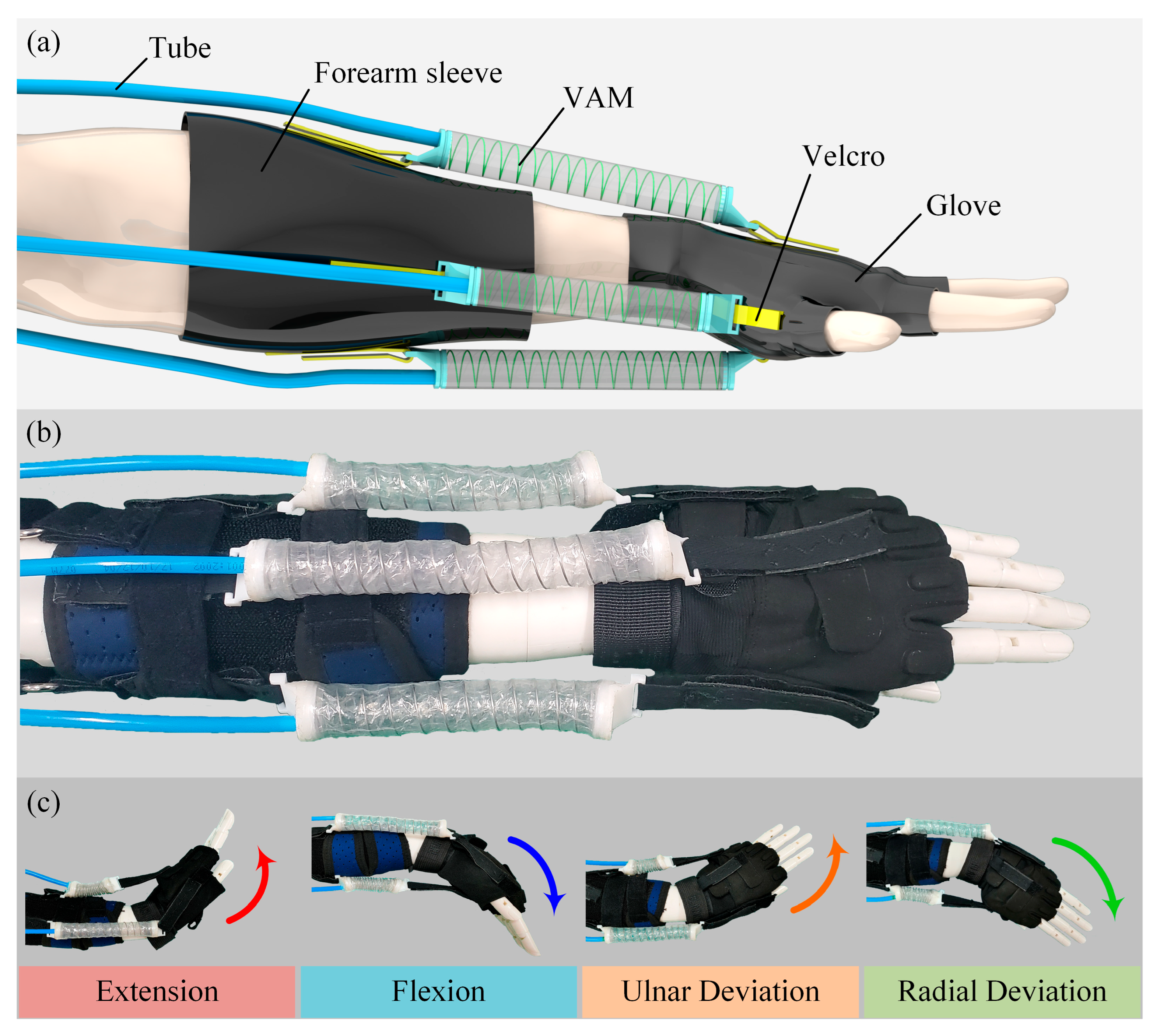
2.1. Design of the WWRD
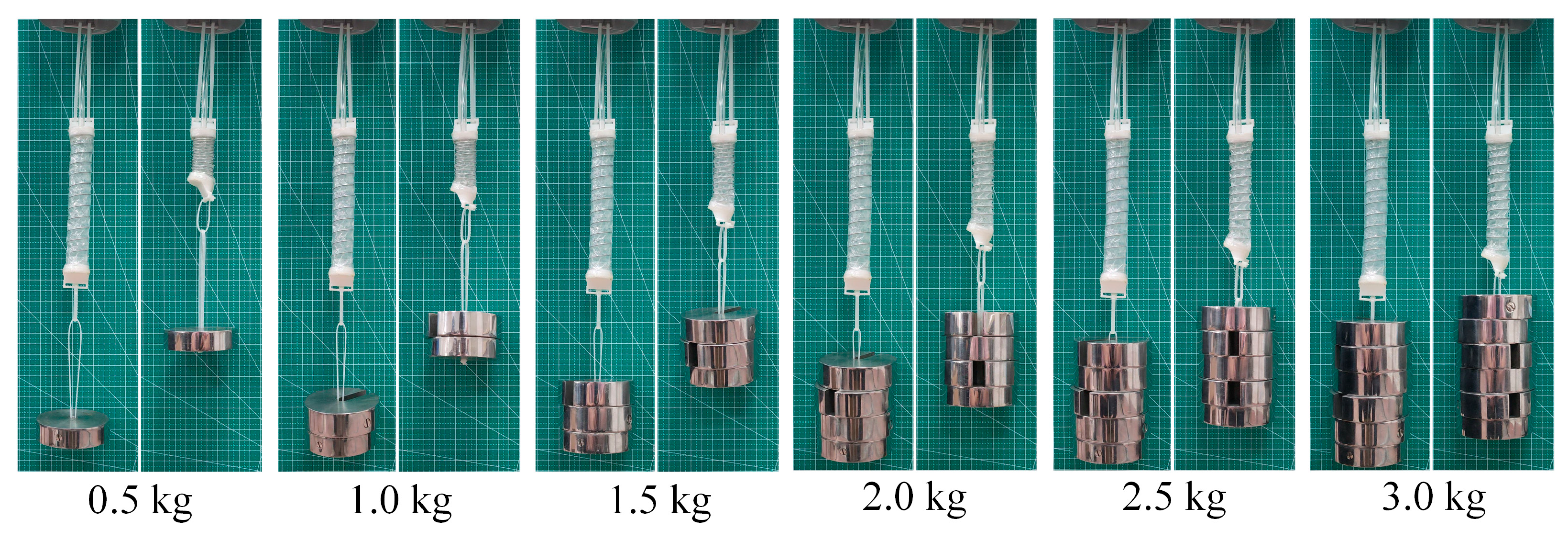
The design of the VAM-based wrist is depicted in Figure 1. For the purpose of wrist rehabilitation training in the motion directions of flexion/extension (first degree of freedom, DOF) and radial/ulnar deviation (second DOF), a new 2-degree of freedom (2-DOF) wearable wrist rehabilitation device (WWRD) was developed. This device employs four vacuum artificial muscles (VAMs) arranged around the wrist joint to actuate these two DOFs, as shown in Figure 1.
When the air in one VAM is pumped out to form a vacuum state, the VAW will be contracted to pull the wrist joint to rotate in the corresponding direction, and the other VAM in the opposite direction will be elongated. As shown in Figure 1b, the actuators in the contraction and elongation state are marked as red and green, respectively. Through the periodic contraction and elongation of VAMs, the rehabilitation training for the tendons and muscles of the wrist joint can be completed.
As shown in Figure 2a,b, the WWRD is mainly composed of a wearing suit and four VAM actuators. The wearing suit mainly includes a forearm sleeve and glove, which are made of medical fabric material. The tightness between the wearable suit and the human upper limb can be adjusted according to the rehabilitation requirements and wearing comfort of patients. Both ends of a VAM are fixed on the forearm sleeve and glove of the wearable suit using velcro, which can be installed, adjusted, and disassembled according to the requirements of rehabilitation training. In the initial state, the internal air pressure of a VAM is equal to the external air pressure. However, as the air in the VAM is pumped out, a low air pressure state will be formed in the air chamber of the VAM. Under the action of internal and external pressure difference (relative pressure), the VAM is compressed and pulls the wrist joint to rotate in the corresponding direction, as shown in Figure 2c. Through the cooperative control of the VAMs in four directions, the needs of wrist rehabilitation training in the direction of extension, flexion, ulnar deviation, and radial deviation will be met.

2.2. Design of VAM

For the development of the wearable wrist rehabilitation device, the choice of actuation is of paramount importance. Considering the fact that it will be installed on the wearable suit around the wrist, there is an urgent need to choose an actuator that is lightweight, flexible, safe, powerful, and cheap. The actuators of artificial muscle type characterized by flexibility and bionic properties have always been of interest to researchers and manufacturers. Considering the high safety and contraction ratio of vacuum-actuated actuators, the proposed VAM macroscopically simulates some inherent functions of natural muscle, which combines the power, accuracy, and durability of mechanical drives with the safety, compliance, and efficiency of natural muscles. Referring to the motion principle and structural form of tendons and muscles, the proposed VAM is mainly composed of a membrane, spring, and two sealing plugs, as shown in Figure 3a. The VAM was fabricated using the following materials and processes. A compression spring composed of 304 stainless steel (wire diameter: 0.8 mm, outer diameter: 14 mm, free length: 167 mm, sourced from Dingli Hardware, Zhuhai, China), a tubular film membrane (thickness: 0.05 mm, inner diameter: 18 mm, sourced from Internet Information Plastic Packaging, Henan, China), and 3D-printed sealing plugs (fabricated using a Bambu Lab A1 3D printer from Top Bamboo Technology Company, Shenzhen, China). High-viscosity rubber stick hot melt adhesive (diameter: 11 mm, sourced from Rui’er Hardware Specialty Store, Jiangsu, China) was used for sealing. The fabrication process involved, first, selecting the spring based on design dimensions; second, cutting the tubular film to length; third, placing the spring concentrically within the film; fourth, inserting the 3D-printed plugs into both ends of the film (one side of each plug features a groove for spring installation and the other side incorporates a rectangular channel for velcro attachment); finally, sealing the critical joints between the film and plugs with the hot melt adhesive to form an airtight chamber structure.
In the initial equilibrium state, the pressures of the internal air and the external air are equal. As the air in the air chamber is extracted, the VAM will be compressed due to the pressure difference. If the internal and external air pressure is balanced again, the VAM will return to its initial state under the action of spring.
The wrist rotation driven by the WWRD mainly depends on the contraction of the VAM. Contraction displacement is one of the important indexes to evaluate the performance of a VAM. To clarify the contraction displacement of a VAM under different relative pressures, the VAM contraction experiment was carried out, as shown in Figure 3c. To analyze the contraction of the VAM more intuitively, the relationship curve between the contraction displacement and relative pressure of the VAM is drawn as the blue curve in Figure 3b, and the relationship between the contraction percentage and relative pressure of the VAM is drawn as the red curve in Figure 3b. The experimental results show that the length of the VAM (original length is 167 mm) is shortened to 5.8 mm when the relative pressure in the VAM is −80 kPa. Its maximum contraction displacement is 109 mm, and the contraction ratio reaches 65.27%.
Output force is another important index to evaluate the performance of the VAM. To assess the force performance of the VAM, its ends were hung with different weights to observe the contraction of the VAM where the relative pressure is −80 kPa; the experimental results are shown in Figure 4. It can be observed that it is easy for the VAM to lift a 1 kg weight. However, the contraction displacement of a VAM will decrease with the increase in weight, which is due to the limitation of the VAM structure. The maximum output force of the VAM mainly depends on the air action area and the pressure difference between the air chamber and the external environment. Since the pressure difference and air action area are determined, the maximum output force of a VAM is limited. A spring is selected as the skeleton of the VAM to maintain the initial shape, which produces resistance during contraction, resulting in the reduction of VAM output force. In addition, the membrane will be tightly attached to the periphery of the spring under the action of the pressure difference, which increases the equivalent stiffness of the VAM. Therefore, the equivalent stiffness and motion resistance of the VAM will increase with the increase in contraction displacement, as evidenced by the curve change trend in Figure 3b, which leads to the decrease in output force of the VAM with the increase in contraction displacement.

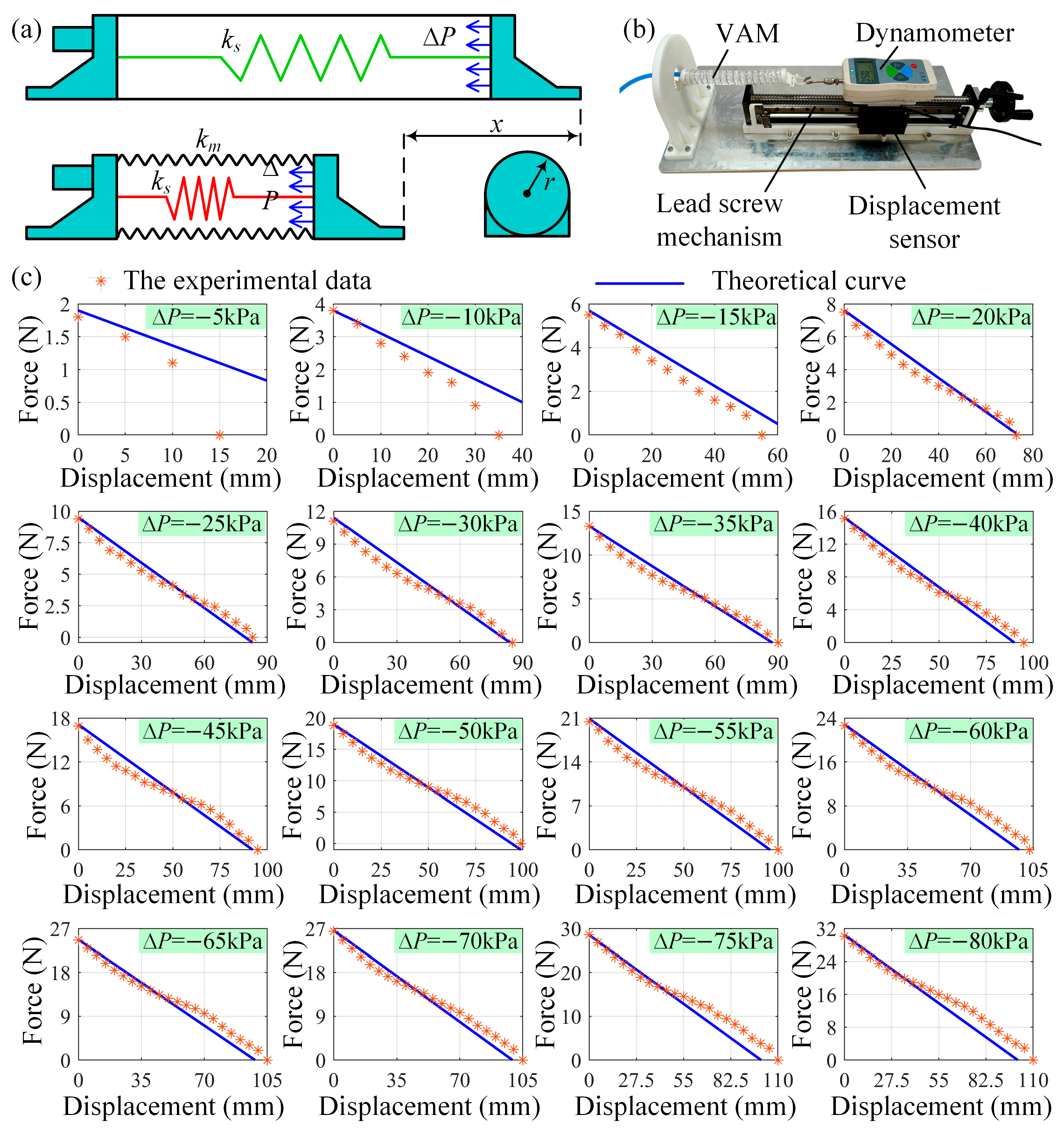
2.3. The Statics Analysis of the VAM

To further clarify the relationship between the contraction displacement, relative pressure, and output force of the VAM, a simplified mechanical model is developed, as shown in Figure 5a. According to the principle of force balance, the output force of the VAM can be expressed as:
F o u t p u t = F p Δ P F k ( x )
where Fp(∆P) is the force induced by the relative pressure in the air chamber of the VAM, Fk(x) is the force generated by the deformation of the VAM.
The force Fp(∆P) in this model can be calculated as:
F p Δ P = Δ P S = Δ P π r 2
where ∆P is the relative pressure in the air chamber of the VAM; S is the effective area of the VAM subject to inner pressure, that is, the cross-section area of the sealing plug; r is the radius of the sealing plug, r = 11 mm.
The force Fk(x) in this model can be calculated as:
F k x = k x = ( k s + k m ) x
where k is the equivalent coefficient of elasticity, x is the contraction displacement of the VAM; ks is the elastic coefficient of the spring, ks = 0.037 N/mm; km is the additional elastic coefficient caused by the contact between the membrane and spring.
It can be observed from Figure 3 that the stiffness of the VAM will increase with the increase in the contraction displacement. The membrane is tightly attached to the spring under the action of the relative pressure, which increases the equivalent stiffness of the VAM. Therefore, the additional elastic coefficient km is a function of the relative pressure ∆P; it can be estimated as:
k m = k p Δ P + b
where kp and b are two constant coefficients. Based on Equations (2)–(4), we can obtain a complete expression for Equation (1):
F o u t p u t = Δ P π r 2 ( k s + k p Δ P + b ) x
To determine the coefficients kp and b in (1), a test system was developed for the relationship between the contraction displacement and output force of the VAM at different relative pressures. The test system for the VAM is shown in Figure 5b. In the experiment, the relative pressure in the VAM was controlled at a given value, the end position of the VAM was changed by the lead screw mechanism, and the displacement data was measured and recorded by a displacement sensor. The output force of the VAM was measured by a dynamometer; the measurement data are shown in Figure 5c. The data points represent experimentally measured values, while the curve denotes the theoretical model.
Through the fitting and analysis of these experimental data, the coefficients k1 and b can be determined, where k1 = 3.5, b = 0, and the theoretical curves (blue curves) and the experimental data (orange points) at different relative pressures (from −5 kPa to −80 kPa) are shown in Figure 5c. It can be observed from Figure 5c that there are some errors between the theoretical curve and experimental data within the range of the relative pressure from 0 to −20 kPa. The error is mainly due to the relatively high stiffness of the membrane at the initial stage of the VAM deformation, which leads to the smaller actual output force of the VAM compared with the theoretical curve. The theoretical model of the VAM under low pressure is relatively complex. Considering that the VAMs in this work are rarely used in low-pressure states, the existing simplified theoretical model is considered to be suitable for the subsequent analysis.

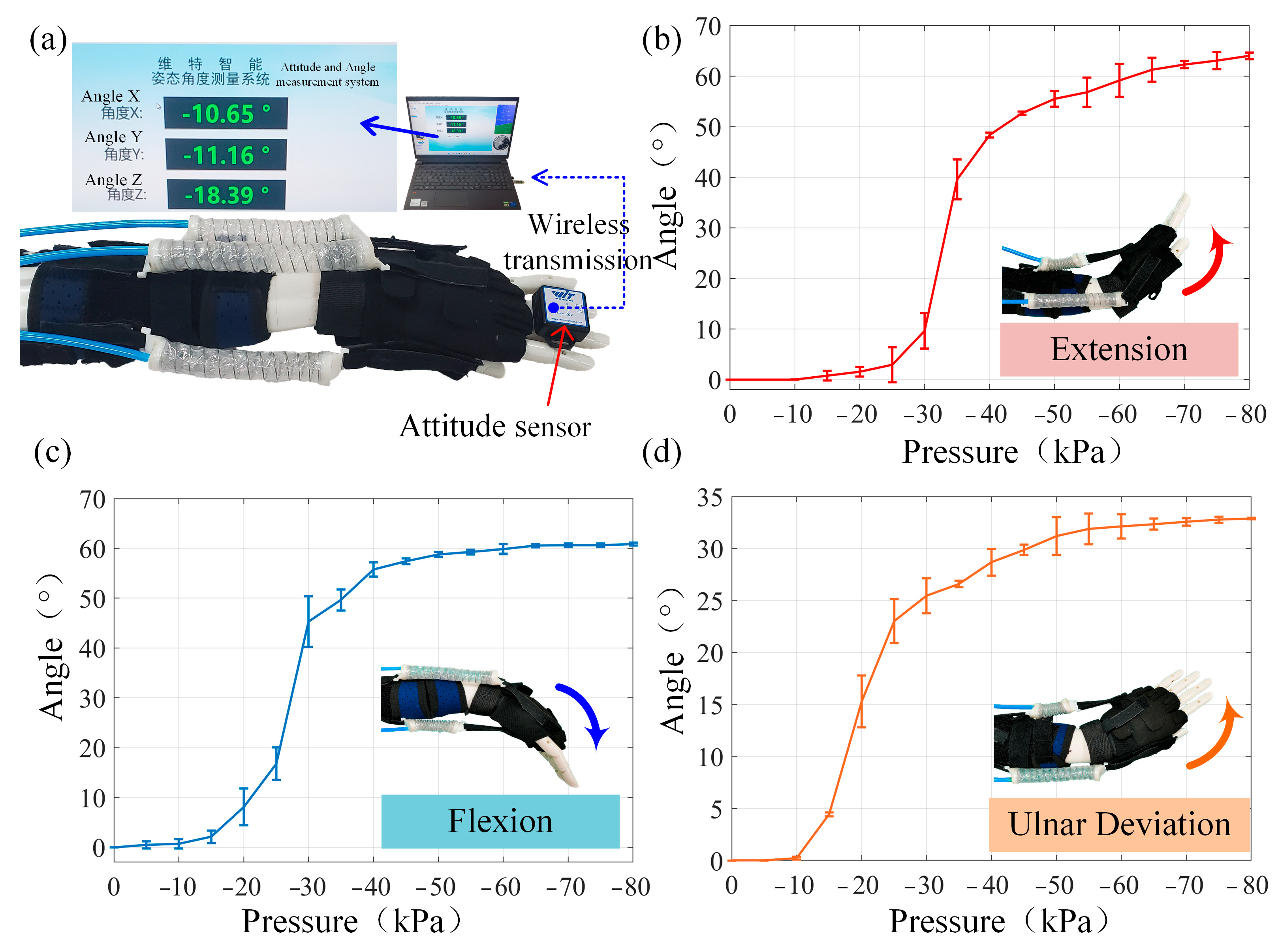
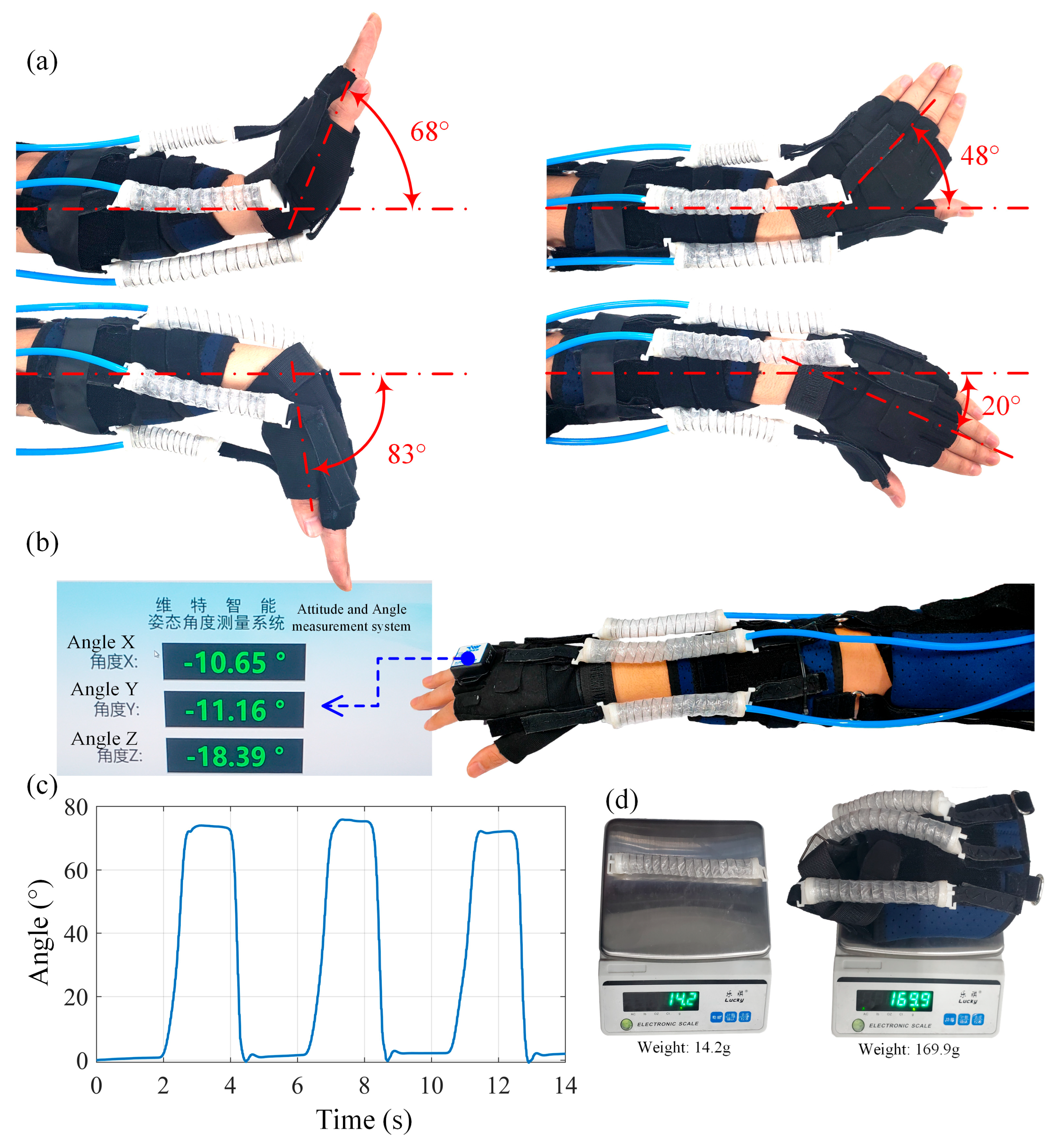
3. Motion Analysis of the WWRD

The wrist rehabilitation training realized by the WWED mainly includes four motions: extension (0–70°), flexion (0–90°), ulnar deviation (0–50°), and radial deviation (0–20°) [40]. The VAM needs to be installed at the corresponding position of the wrist according to the requirements of rehabilitation training. The contraction of the VAM drives the wrist joint to rotate in the corresponding direction to realize the rehabilitation training.

3.1. Analysis of Multidirectional Wrist Motions: Ulnar Deviation, Radial Deviation, Extension, and Flexion

To analyze the maximum force and contraction displacement of the VAM required in the rehabilitation training of wrist ulnar deviation, radial deviation, extension, and flexion, a simplified mechanical model of wrist ulnar deviation, radial deviation, extension, and flexion is developed as shown in Figure 6. One end of the VAM is fixed on the point A on the forearm, and the other end is fixed on the point B on the hand. It is assumed that the rotation center of the wrist joint is point O and remains unchanged in the process of wrist extension.
The values of parameters LOA, LOB, α, β, and LOC in Table 1 were obtained from the actual measurement method shown in Figure 6. The parameter G (11.5 N) was determined by combining the static gravity of the palm equivalent mass (0.5–0.7 kg, yielding 5.9–6.9 N) with safety factors (1.5–2.0), which complies with the mandatory requirements for static loads specified in the Chinese National Standard GB/T 37704-2019 General Technical Specifications for Sports Rehabilitation Training Robots [41]. These parameters were validated through Equation (6) and subsequent static analyses to ensure the rationality of the structural design.
To simplify the analysis, it is assumed that the biological tissue of the wrist joint does not participate in rehabilitation training, which does not produce driving force and movement resistance affecting the rotation of the wrist joint. All the driving force required for wrist ulnar deviation, radial deviation, extension, and flexion is provided by the VAM.
According to the cosine theorem, the distance between point A and point B (the length of the VAM) can be calculated as:
L A B = L O A 2 + L O B 2 2 L O A L O B cos δ
where LOA and LOB is the distance from the point A to the rotation center O and the point B to the rotation center O. δ is the angle between the line OA and the line OB. According to the geometric relationship, δ can be expressed as:
δ = π α β γ
where α is the angle between the line OA and the central axis of the forearm; β is the angle between the line OB and the central axis of the hand; γ is the angle of the hand deviates from its initial position, that is, the rotation angle of the wrist joint.
According to the sine theorem, the sine value of the angle between the line AB and the line OA can be calculated as:
sin ε = L O B sin δ L A B
According to the trigonometric function relationship, the force arms LV and LG can be calculated as:
L V = L O A sin ε L G = L O C cos γ
where LOC is the distance between the center of gravity of the hand and the rotation center of the wrist joint in the initial state.

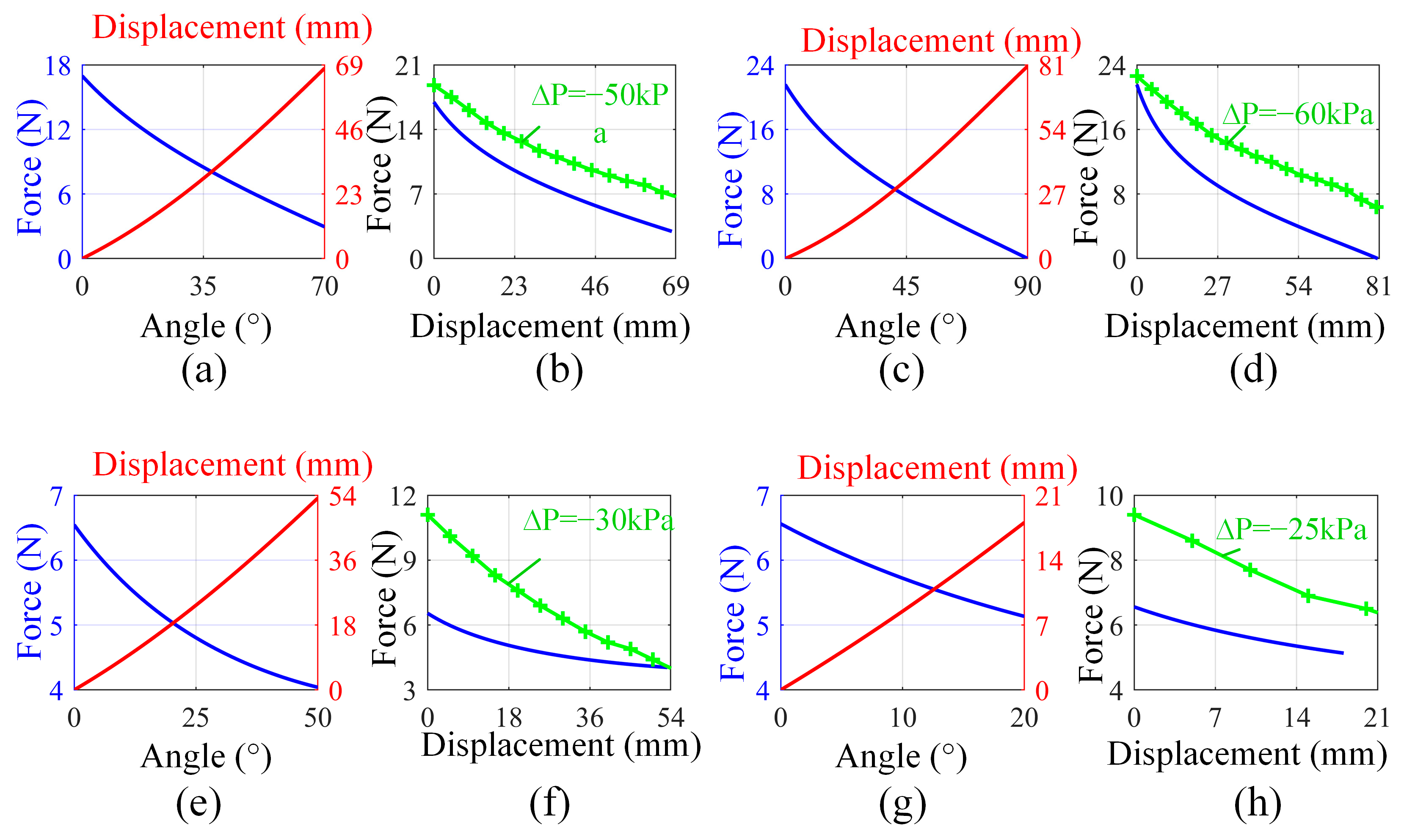
3.2. The Mechanical Analysis of Wrist Extension and Flexion Motions

According to the principle of moment balance, the output force of the VAM can be expressed as:
F V = G L G L V
where FV is the output force of the VAM; LV is the arm of the force FV; G is the hand gravity; and LG is the force arm of the hand gravity G.
Based on Equations (6)–(10), the output force of the VAM can be expressed as:
F V = G L O C cos γ L O A L O B sin ( π α β γ ) L O A 2 + L O B 2 2 L O A L O B cos ( π α β γ )
The rotation angle range of the wrist extension is 0–70°. According to (11), the relationship curve between the output force of the VAM and the rotation angle of the wrist joint was drawn as the blue curve in Figure 7a. According to Equations (6) and (10), the relationship curve between the contraction displacement of the VAM and the rotation angle of the wrist joint is drawn as the red curve in Figure 7a. In the process of wrist extension, the maximum force required by the wrist extension is 16.97 N, and the required maximum contraction displacement of the VAM is 67.81 mm. It can be observed from Figure 7b that the rehabilitation training of the wrist extension will be realized when the relative pressure of the VAM is higher than −50 kPa. Therefore, the designed VAM meets the rehabilitation training requirements of wrist extension.
The rotation angle range of wrist flexion is 0–90°. The corresponding parameters in the process of the wrist flexion are substituted into (6) and (11), which can obtain the relationship curve between the output force of the VAM and the rotation angle of the wrist joint, as the blue curve in Figure 7c. The relationship curve between the contraction displacement of the VAM and the rotation angle of the wrist joint was drawn as the red curve in Figure 7c. In the process of wrist flexion, the maximum force required by the wrist extension is 21.56 N, and the required maximum contraction displacement of the VAM is 80.49 mm. It can be observed from Figure 7d that the rehabilitation of wrist flexion will be realized when the relative pressure of the VAM is higher than −60 kPa. Therefore, the designed VAM meets the rehabilitation training requirements of wrist flexion.

3.3. The Mechanical Analysis of Wrist Ulnar Deviation and Radial Deviation Motions

Generally, the method that the hand is placed on the horizontal plane (desktop) and driven by the VAM in the horizontal direction is adopted in the rehabilitation training of wrist ulnar deviation and radial deviation. In this way, the most resistance the VAM needs to overcome is no longer the hand gravity but the friction between the hand gravity and the desktop. As shown in Figure 6c,d, according to the principle of moment balance, the output force of the VAM can be expressed as:
F V = F R L R L V = k f G L O C L V
where FV is the output force of the VAM; LV is the arm of the force FV; FR is the maximum resistance that the VAM needs to overcome; LR is the arm of the resistance FR, LR = LOC; kf is the friction coefficient between the gravity of the hand and the desktop; G is the hand gravity.
Based on Equations (6)–(12), we can obtain a complete expression for Equation (11):
F V = k f G L O C L O A L O B sin δ
The rotation angle range of wrist flexion is 0–50°. According to (13), the relationship curve between the output force of the VAM and the rotation angle of the wrist joint is drawn as the blue curve in Figure 7e. According to Equation (6), the relationship curve between the contraction displacement of the VAM and the rotation angle of the wrist joint is drawn as the red curve in Figure 7e. In the process of wrist ulnar deviation, the maximum force required by the wrist ulnar deviation is 6.54 N, and the required maximum contraction displacement of the VAM is 53.21 mm. It can be observed from Figure 7f that the rehabilitation of the wrist ulnar deviation will be realized when the relative pressure of the VAM is higher than −30 kPa. Therefore, the designed VAM meets the rehabilitation training requirements for wrist ulnar deviation.
The rotation angle range of wrist radial deviation is 0–20°. The corresponding parameters in the process of wrist radial deviation are substituted into Equations (6) and (11), which can obtain the relationship curve between the output force of the VAM and the rotation angle of the wrist joint, shown as the blue curve in Figure 7g. The relationship curve between the contraction displacement of the VAM and the rotation angle of the wrist joint was drawn as the red curve in Figure 7g. In the process of wrist radial deviation, the maximum force required by the wrist radial deviation is 6.56 N, and the required maximum contraction displacement of the VAM is 18.06 mm. It can be observed from Figure 7h that the rehabilitation of wrist radial deviation will be realized when the relative pressure of the VAM is higher than −25 kPa. Therefore, the designed VAM meets the rehabilitation training requirements of wrist radial deviation.

4. Wearing Experiments of WWRD

To measure the relationship between the rotation angle of the WWRD and the relative pressure of the VAM, a test system for the WWRD was built, as shown in Figure 8a. To eliminate the interference of human factors, the WWRD was worn on a simple prosthesis to carry out the experiment. The attitude sensor was placed on the hand of the prosthesis to measure the angle change of the wrist joint, and the angle data was sent to the host computer through a Bluetooth module for recording.
The radial deviation motion of the wrist joint in the human body is very small, and its rotation angle is usually less than 20°. However, the prosthesis selected in this experiment is relatively simple, so the maximum radial deviation angle of the wrist is consistent with the maximum ulnar deviation angle (about 35°), which greatly exceeds the actual radial deviation angle. Therefore, the experiments on the prosthesis only tested the relationship between the relative pressure and the rotation angle of the WWRD in the motion direction of extension, flexion, and ulnar deviation.
The experimental results are shown in Figure 8b, Figure 8c and Figure 8d, respectively. With the help of the WWRD, the maximum range of the motions was measured as extension 64°, flexion 61°, and ulnar deviation 35°, which is limited by the maximum rotation angle of the prosthesis.
The rotation angle ranges of the wrist joint assisted by the WWRD during practical rehabilitation training were recorded and measured, as shown in Figure 8a. The maximum range of the motions was measured as extension 68°, flexion 83°, ulnar deviation 48°, and radial deviation 20°. To quantitatively assess the capability of the WWRD in meeting rehabilitation requirements, these ranges were compared against established normative values for healthy wrist motion. Published studies report average ranges [42,43,44,45] (mean ± standard deviation) as follows: flexion 70.9° ± 10.6°, extension 65.7° ± 6.8°, radial deviation 26.3° ± 7.0°, and ulnar deviation 40.1° ± 5.2° %. This corresponds to typical functional ranges of approximately 60.3° to 81.5° for flexion, 58.9° to 72.5° for extension, 19.3° to 33.3° for radial deviation, and 34.9° to 45.3° for ulnar deviation. The comparison demonstrates that the WWRD’s maximum flexion (83°) comfortably exceeds the upper end of the normative flexion range (~81.5°), while its maximum extension (68°) falls within the normative extension range (~58.9–72.5°) and surpasses the average value. For ulnar deviation, the achieved maximum (48°) significantly exceeds the upper limit of the normative range (~45.3°). Although the radial deviation achieved (20°) is below the normative average (26.3°), it reaches the lower boundary of the typical healthy range (~19.3°). Therefore, the WWRD can meet the requirements of the wrist rehabilitation training range.
To study the compliance and safety of the WWRD in practical rehabilitation training, taking the wrist extension motion as an example, the change trend of the wrist rotation angle was measured and analyzed, as shown in Figure 9b. The curve shown in Figure 9c is the real-time change curve recorded by the attitude sensor installed on the hand when the relative pressure of the WWRM changes periodically. It can be observed from Figure 9c that in the process of the wrist extension motion, the movement of the WWRD is compliant and will not cause secondary injury to the wrist joint, showing great safety. The developed WWRD was made of highly elastic medical fabric materials, showing excellent lightness and comfort; for example, the weight of a single VAM is only 14.2 g, and the weight of the WWRD worn on the human body is around 169.9 g, as shown in Figure 9d, which is comparable to the state-of-the-art lightweight wrist rehabilitation device.

5. Conclusions and Future Work

The wrist joint is an important and complex part of the human upper limb system. Its complex structure supports the hand to complete all kinds of dexterous and accurate operations in daily living, which in turn makes it vulnerable to motor injury due to stroke, sports, occupational, or traffic accidents. Timely and effective rehabilitation training can accelerate the recovery process of wrist motor function, in addition to traditional medical treatment. This wearable rehabilitation device is a new rehabilitation training device for injured joints, which shows excellent application prospects in the field of human rehabilitation training due to its inherent flexibility and safety.
Inspired by the motion principle and structural form of tendons and muscles, a modular vacuum-actuated artificial muscle (VAM) is proposed in this work, which could produce the same contraction effect as tendons and muscles. The VAM was mainly composed of a spring, membrane, and two sealing plugs; its weight is 14.2 g and the contraction ratio is 65%, showing the advantages of being lightweight and having a high contraction ratio. The VAMs were applied to the development of a wearable wrist rehabilitation device (WWRD) prototype, which can realize wrist rehabilitation training in the motion directions of extension, flexion, ulnar deviation, and radial deviation through the four VAMs arranged around the wrist joint. The weight of the proposed WWRD prototype is only 169.9 g, which is comparable to the existing lightweight wrist rehabilitation devices and brings a comfortable wearing experience to patients.
The design concept, structural model, and motion analysis of the WWRD are introduced in this work to provide a reference for the design and analysis of the WWRD based on an understanding of the VAMs. The relationship of the relative pressure, contraction displacement, and output force of a VAM was analyzed to form a simplified parameter model of the VAM. The theoretical model of the relationship between the relative pressure of the WWRD and the rotation angle of the wrist joint was established to analyze the minimum length and the maximum output force of the VAM required in wrist rehabilitation training. A test system for the WWRD worn on a simple prosthesis was built to measure the relationship between the rotation angle and the relative pressure of the WWRD. Experimental results verified the rationality of theoretical analysis and illustrated the effect of wrist rehabilitation training. To observe the practical rehabilitation training effect of the WWRD, the maximum rotation angle of the wrist joint assisted by the WWRD was recorded and measured as extension 68°, flexion 83°, ulnar deviation 48°, and radial deviation 20°, which meet the requirements of the wrist rehabilitation training range. Finally, the process of wrist rehabilitation training was tested and analyzed, which indicated the compliance and safety of the WWRD.
Future work will focus on the integration and research of the control and drive system in lightweight wearable wrist rehabilitation systems. We intend to further optimize the structure and design of the WWRD to develop a compact wrist training system that can carry out rehabilitation training anytime and anywhere in the daily living environment. Additionally, how to improve the accuracy of the control model between the input parameters and output parameters of the WWRD is still a subject worthy of further study. We consider that it is possible to accurately control the position of the wrist through the feedback information provided by the integrated sensors. These are just some preliminary ideas, and we will continue to explore effective ways to develop more high-performance wearable wrist rehabilitation devices based on an understanding of the bioinspired vacuum-actuated artificial muscles.

Author Contributions

Conceptualization, X.C.; Funding acquisition, J.Y.; Investigation, W.G.; Project administration, J.Y.; Validation, K.Z. and F.H.; Writing—original draft, X.C.; Writing—review and editing, F.H. All authors have read and agreed to the published version of the manuscript.

Funding

This research was funded by The National Natural Science Foundation Of China, grant number 52375030, was funded by The Hebei Provincial Natural Science Foundation—Beijing-Tianjin-Hebei Collaborative Innovation Special Program, grant number E2024203254, and was funded by The Innovation Capability Cultivation Funding Project For Postgraduate Students By Hebei Provincial Department Of Education, grant number CXZZSS2025036.

Data Availability Statement

The raw data supporting the conclusions of this article will be made available by the authors upon request.

Conflicts of Interest

The authors declare no conflicts of interest.

References

  1. Huang, B.; Li, M.; Mei, T.; McCoul, D.; Qin, S.; Zhao, Z.; Zhao, J. Wearable Stretch Sensors for Motion Measurement of the Wrist Joint Based on Dielectric Elastomers. Sensors 2017, 17, 2708. [Google Scholar] [CrossRef] [PubMed]
  2. Caumes, M.; Goislard de Monsabert, B.; Hauraix, H.; Berton, E.; Vigouroux, L. Complex Couplings between Joints, Muscles and Performance: The Role of the Wrist in Grasping. Sci. Rep. 2019, 9, 19357. [Google Scholar] [CrossRef] [PubMed]
  3. Stuelcken, M.; Mellifont, D.; Gorman, A.; Sayers, M. Wrist Injuries in Tennis Players: A Narrative Review. Sports Med. 2017, 47, 857–868. [Google Scholar] [CrossRef]
  4. Hendricks, H.T.; Van Limbeek, J.; Geurts, A.C.; Zwarts, M.J. Motor Recovery after Stroke: A Systematic Review of the Literature. Arch. Phys. Med. Rehabil. 2002, 83, 1629–1637. [Google Scholar] [CrossRef]
  5. Brewer, B.R.; McDowell, S.K.; Worthen-Chaudhari, L.C. Poststroke Upper Extremity Rehabilitation: A Review of Robotic Systems and Clinical Results. Top. Stroke Rehabil. 2007, 14, 22–44. [Google Scholar] [CrossRef]
  6. Okita, S.; Schwerz De Lucena, D.; Reinkensmeyer, D.J. Movement Diversity and Complexity Increase as Arm Impairment Decreases After Stroke: Quality of Movement Experience as a Possible Target for Wearable Feedback. IEEE Trans. Neural Syst. Rehabil. Eng. 2024, 32, 2961–2970. [Google Scholar] [CrossRef] [PubMed]
  7. Sanjuan, J.D.; Castillo, A.D.; Padilla, M.A.; Quintero, M.C.; Gutierrez, E.E.; Sampayo, I.P.; Hernandez, J.R.; Rahman, M.H. Cable Driven Exoskeleton for Upper-Limb Rehabilitation: A Design Review. Robot. Auton. Syst. 2020, 126, 103445. [Google Scholar] [CrossRef]
  8. Cerasa, A.; Pignolo, L.; Gramigna, V.; Serra, S.; Olivadese, G.; Rocca, F.; Perrotta, P.; Dolce, G.; Quattrone, A.; Tonin, P. Exoskeleton-Robot Assisted Therapy in Stroke Patients: A Lesion Mapping Study. Front. Neuroinform. 2018, 12, 44. [Google Scholar] [CrossRef]
  9. Hussain, S.; Jamwal, P.K.; Van Vliet, P.; Ghayesh, M.H. State-of-the-Art Robotic Devices for Wrist Rehabilitation: Design and Control Aspects. IEEE Trans. Hum.-Mach. Syst. 2020, 50, 361–372. [Google Scholar] [CrossRef]
  10. Bertani, R.; Melegari, C.; De Cola, M.C.; Bramanti, A.; Bramanti, P.; Calabrò, R.S. Effects of Robot-Assisted Upper Limb Rehabilitation in Stroke Patients: A Systematic Review with Meta-Analysis. Neurol. Sci. 2017, 38, 1561–1569. [Google Scholar] [CrossRef]
  11. Dalla Gasperina, S.; Roveda, L.; Pedrocchi, A.; Braghin, F.; Gandolla, M. Review on Patient-Cooperative Control Strategies for Upper-Limb Rehabilitation Exoskeletons. Front. Robot. AI 2021, 8, 745018. [Google Scholar] [CrossRef] [PubMed]
  12. Keller, U.; Van Hedel, H.J.A.; Klamroth-Marganska, V.; Riener, R. ChARMin: The First Actuated Exoskeleton Robot for Pediatric Arm Rehabilitation. IEEE/ASME Trans. Mechatron. 2016, 21, 2201–2213. [Google Scholar] [CrossRef]
  13. Wu, Q.; Wang, X.; Chen, B.; Wu, H. Development of a Minimal-Intervention-Based Admittance Control Strategy for Upper Extremity Rehabilitation Exoskeleton. IEEE Trans. Syst. Man Cybern. Syst. 2018, 48, 1005–1016. [Google Scholar] [CrossRef]
  14. Wu, K.-Y.; Su, Y.-Y.; Yu, Y.-L.; Lin, C.-H.; Lan, C.-C. A 5-Degrees-of-Freedom Lightweight Elbow-Wrist Exoskeleton for Forearm Fine-Motion Rehabilitation. IEEE/ASME Trans. Mechatron. 2019, 24, 2684–2695. [Google Scholar] [CrossRef]
  15. Raiano, L.; Di Pino, G.; Di Biase, L.; Tombini, M.; Tagliamonte, N.L.; Formica, D. PDMeter: A Wrist Wearable Device for an at-Home Assessment of the Parkinson’s Disease Rigidity. IEEE Trans. Neural Syst. Rehabil. Eng. 2020, 28, 1325–1333. [Google Scholar] [CrossRef]
  16. Gopura, R.A.R.C.; Bandara, D.S.V.; Kiguchi, K.; Mann, G.K.I. Developments in Hardware Systems of Active Upper-Limb Exoskeleton Robots: A Review. Robot. Auton. Syst. 2016, 75, 203–220. [Google Scholar] [CrossRef]
  17. Sung, J.; Choi, S.; Kim, H.; Lee, G.; Han, C.; Ji, Y.; Shin, D.; Hwang, S.; Yun, D.; Jang, H.; et al. Feasibility of Rehabilitation Training with a Newly Developed, Portable, Gait Assistive Robot for Balance Function in Hemiplegic Patients. Ann. Rehabil. Med. 2017, 41, 178. [Google Scholar] [CrossRef] [PubMed]
  18. Wu, Q.; Wang, X.; Chen, B.; Wu, H. Development of an RBFN-Based Neural-Fuzzy Adaptive Control Strategy for an Upper Limb Rehabilitation Exoskeleton. Mechatronics 2018, 53, 85–94. [Google Scholar] [CrossRef]
  19. Wang, Y.; Xu, Q. Design and Testing of a Soft Parallel Robot Based on Pneumatic Artificial Muscles for Wrist Rehabilitation. Sci. Rep. 2021, 11, 1273. [Google Scholar] [CrossRef]
  20. Wang, J.; Fei, Y.; Chen, W. Integration, Sensing, and Control of a Modular Soft-Rigid Pneumatic Lower Limb Exoskeleton. Soft Robot. 2020, 7, 140–154. [Google Scholar] [CrossRef]
  21. Liu, Q.; Zuo, J.; Zhu, C.; Xie, S.Q. Design and Control of Soft Rehabilitation Robots Actuated by Pneumatic Muscles: State of the Art. Future Gener. Comput. Syst. 2020, 113, 620–634. [Google Scholar] [CrossRef]
  22. Jeong, J.; Yasir, I.B.; Han, J.; Park, C.H.; Bok, S.-K.; Kyung, K.-U. Design of Shape Memory Alloy-Based Soft Wearable Robot for Assisting Wrist Motion. Appl. Sci. 2019, 9, 4025. [Google Scholar] [CrossRef]
  23. Copaci, D.; Cano, E.; Moreno, L.; Blanco, D. New Design of a Soft Robotics Wearable Elbow Exoskeleton Based on Shape Memory Alloy Wire Actuators. Appl. Bionics Biomech. 2017, 2017, 1605101. [Google Scholar] [CrossRef] [PubMed]
  24. Fang, J.; Yuan, J.; Wang, M.; Xiao, L.; Yang, J.; Lin, Z.; Xu, P.; Hou, L. Novel Accordion-Inspired Foldable Pneumatic Actuators for Knee Assistive Devices. Soft Robot. 2020, 7, 95–108. [Google Scholar] [CrossRef]
  25. Veale, A.J.; Staman, K.; van der Kooij, H. Soft, Wearable, and Pleated Pneumatic Interference Actuator Provides Knee Extension Torque for Sit-to-Stand. Soft Robot. 2021, 8, 28–43. [Google Scholar] [CrossRef]
  26. Polygerinos, P.; Wang, Z.; Galloway, K.C.; Wood, R.J.; Walsh, C.J. Soft Robotic Glove for Combined Assistance and At-Home Rehabilitation. Robot. Auton. Syst. 2015, 73, 135–143. [Google Scholar] [CrossRef]
  27. Liu, S.; Fang, Z.; Liu, J.; Tang, K.; Luo, J.; Yi, J.; Hu, X.; Wang, Z. A Compact Soft Robotic Wrist Brace with Origami Actuators. Front. Robot. AI 2021, 8, 614623. [Google Scholar] [CrossRef]
  28. Ang, B.W.K.; Yeow, C.-H. Design and Modeling of a High Force Soft Actuator for Assisted Elbow Flexion. IEEE Robot. Autom. Lett. 2020, 5, 3731–3736. [Google Scholar] [CrossRef]
  29. O’Neill, C.T.; McCann, C.M.; Hohimer, C.J.; Bertoldi, K.; Walsh, C.J. Unfolding Textile-Based Pneumatic Actuators for Wearable Applications. Soft Robot. 2021, 9, 163–172. [Google Scholar] [CrossRef]
  30. Kwon, J.; Park, J.-H.; Ku, S.; Jeong, Y.; Paik, N.-J.; Park, Y.-L. A Soft Wearable Robotic Ankle-Foot-Orthosis for Post-Stroke Patients. IEEE Robot. Autom. Lett. 2019, 4, 2547–2552. [Google Scholar] [CrossRef]
  31. Bartlett, N.W.; Lyau, V.; Raiford, W.A.; Holland, D.; Gafford, J.B.; Ellis, T.D.; Walsh, C.J. A Soft Robotic Orthosis for Wrist Rehabilitation. J. Med. Devices 2015, 9, 030918. [Google Scholar] [CrossRef]
  32. Andrikopoulos, G.; Nikolakopoulos, G.; Manesis, S. Design and Development of an Exoskeletal Wrist Prototype via Pneumatic Artificial Muscles. Meccanica 2015, 50, 2709–2730. [Google Scholar] [CrossRef]
  33. Chou, C.-P.; Hannaford, B. Measurement and Modeling of McKibben Pneumatic Artificial Muscles. IEEE Trans. Robot. Automat. 1996, 12, 90–102. [Google Scholar] [CrossRef]
  34. Connolly, F.; Walsh, C.J.; Bertoldi, K. Automatic Design of Fiber-Reinforced Soft Actuators for Trajectory Matching. Proc. Natl. Acad. Sci. USA 2017, 114, 51–56. [Google Scholar] [CrossRef]
  35. Li, S.; Vogt, D.M.; Rus, D.; Wood, R.J. Fluid-Driven Origami-Inspired Artificial Muscles. Proc. Natl. Acad. Sci. USA 2017, 114, 13132–13137. [Google Scholar] [CrossRef] [PubMed]
  36. Yang, D.; Mosadegh, B.; Ainla, A.; Lee, B.; Khashai, F.; Suo, Z.; Bertoldi, K.; Whitesides, G.M. Buckling of Elastomeric Beams Enables Actuation of Soft Machines. Adv. Mater. 2015, 27, 6323–6327. [Google Scholar] [CrossRef]
  37. Yang, D.; Verma, M.S.; So, J.-H.; Mosadegh, B.; Keplinger, C.; Lee, B.; Khashai, F.; Lossner, E.; Suo, Z.; Whitesides, G.M. Buckling Pneumatic Linear Actuators Inspired by Muscle. Adv. Mater. Technol. 2016, 1, 1600055. [Google Scholar] [CrossRef]
  38. Kulasekera, A.L.; Arumathanthri, R.B.; Chathuranga, D.S.; Gopura, R.A.R.C.; Lalitharatne, T.D. A thin-walled vacuum actuator (thinvac) and the development of multifilament actuators for soft robotic applications. Sens. Actuators A Phys. 2021, 332, 113088. [Google Scholar] [CrossRef]
  39. Tawk, C.; In Het Panhuis, M.; Spinks, G.M.; Alici, C. Bioinspired 3d printable soft vacuum actuators for locomotion robots, grippers and artificial muscles. Soft Robot. 2018, 5, 685–694. [Google Scholar] [CrossRef]
  40. Rayner, P.; Morita, L.; Sun, X.; Sameoto, D. R3VAMPs—Fully recyclable, reconfigurable, and recoverable vacuum actuated muscle-inspired pneumatic structures. In Proceedings of the 2022 IEEE 5th International Conference on Soft Robotics (RoboSoft), Edinburgh, UK, 4–8 April 2022; IEEE: Piscataway, NJ, USA, 2022; pp. 577–582. [Google Scholar]
  41. GB/T 37704-2019; National Technical Committee 13 on Special Service Robots of Standardization Administration of China. General Specifications for Sports Rehabilitation Training Robots. Standards Press of China: Beijing, China, 2019.
  42. Xu, Y.Q.; Zhong, S.Z.; Zhu, Q.A.; Zhao, W.D.; Li, Z.H.; Li, Z.Y. Experimental study on kinematics of normal wrist joints. Chin. J. Clin. Anat. 2003, 2, 173–175. [Google Scholar]
  43. Behrens, M.; Husmann, F.; Mau-Moeller, A.; Schlegel, J.; Reuter, E.-M.; Zschorlich, V.R. Neuromuscular Properties of the Human Wrist Flexors as a Function of the Wrist Joint Angle. Front. Bioeng. Biotechnol. 2019, 7, 181. [Google Scholar] [CrossRef] [PubMed]
  44. Merritt, W.H.; Wong, A.L.; Lalonde, D.H. Recent Developments Are Changing Extensor Tendon Management. Plast. Reconstr. Surg. 2020, 145, 617e–628e. [Google Scholar] [CrossRef] [PubMed]
  45. Al-Fahaam, H.; Davis, S.; Nefti-Meziani, S. Wrist Rehabilitation Exoskeleton Robot Based on Pneumatic Soft Actuators. In Proceedings of the 2016 International Conference for Students on Applied Engineering (ISCAE), Newcastle upon Tyne, UK, 20–21 October 2016; IEEE: Piscataway, NJ, USA, 2016; pp. 491–496. [Google Scholar]
Figure 1. Design principle of wrist rehabilitation training. (a) The wrist rotates under the action of ligaments and muscles. (b) Design principle of wrist rehabilitation training in the motion direction of extension, flexion, ulnar deviation, and radial deviation.
Actuators 14 00304 g001
Figure 2. Structural model and prototype of the WWRD. (a) Structural model of the WWRD. (b) Experimental prototype of the WWRD. (c) Movement of the WWRD prototype in the direction of extension, flexion, ulnar deviation, and radial deviation.
Actuators 14 00304 g002
Figure 3. Structural model of a VAM and its contraction experiment. (a) Structural model of a VAM in initial state and contraction state. (b) The blue curve is the relationship between the contraction displacement and the relative pressure of the VAM, and the red curve is the relationship between the contraction ratio and the relative pressure of the VAM. (c) Experimental results of the contraction of the VAM.
Actuators 14 00304 g003
Figure 4. VAM can lift different weights.
Actuators 14 00304 g004
Figure 5. Performance testing for a VAM. (a) Force diagram of a VAM. (b) Test system for a VAM. (c) Relationship between the output force and contraction displacement of the VAM under different relative pressures.
Actuators 14 00304 g005
Figure 6. Movement and force analysis of wrist. (a) Extension. (b) Flexion. (c) Ulnar deviation. (d) Radial deviation.
Actuators 14 00304 g006
Figure 7. Parameter relationship curves of the WWRD during wrist rotation. The blue curve represents the change of force with the change of the horizontal coordinate. The red curve represents the change of displacement with the change of the horizontal coordinate. (a,b) are the relationship curves between the rotation angle, force, and contraction displacement of the WWRD in the direction of extension. (c,d) are the relationship curves between the rotation angle, force, and contraction displacement of the WWRD in the direction of flexion. (e,f) are the relationship curves between the rotation angle, force, and contraction displacement of the WWRD in the direction of ulnar deviation. (g,h) are the relationship curves between the rotation angle, force, and contraction displacement of the WWRD in the direction of radial deviation.
Actuators 14 00304 g007
Figure 8. Experiment for the WWRD worn on the prosthesis. (a) Test system for the WWRD. (b) Relationship between the relative pressure and the rotation angle of the WWRD in the wrist extension motion. (c) Relationship between the relative pressure and the rotation angle of the WWRD in the wrist flexion motion. (d) Relationship between the relative pressure and the rotation angle of the WWRD in the wrist ulnar deviation motion.
Actuators 14 00304 g008
Figure 9. (a) The rotation angle ranges of the wrist joint assisted by the WWRD in practical rehabilitation training. (b) Test system for the WWRD worn on the wrist joint. (c) Rotation angle change curve in the process of wrist extension motion. (d) Weight of a VAM and WWRD.
Actuators 14 00304 g009
Table 1. Parameters of the WWRD worn in the wrist joint.
ParameterExtensionFlexionUlnar DeviationRadial Deviation
LOA (mm)144143133151
LOB (mm)69637771
α (°)8.5121612
β (°)36254045
G (N)11.511.511.511.5
LOC (mm)51.651.651.651.6
Disclaimer/Publisher’s Note: The statements, opinions and data contained in all publications are solely those of the individual author(s) and contributor(s) and not of MDPI and/or the editor(s). MDPI and/or the editor(s) disclaim responsibility for any injury to people or property resulting from any ideas, methods, instructions or products referred to in the content.

