Article

Development of a Novel Digital Pressure Control Valve Applied to Emulsion Pump Station Control and Research on the Performance of Its Dynamic Characteristics

1
College of Mechanical Engineering, Taiyuan University of Technology, Taiyuan 030024, China
2
National and Local Joint Engineering Laboratory for Mining Fluid Control, Taiyuan 030024, China
*
Authors to whom correspondence should be addressed.
Actuators 2025, 14(6), 295; https://doi.org/10.3390/act14060295
Submission received: 15 May 2025 / Revised: 15 June 2025 / Accepted: 16 June 2025 / Published: 17 June 2025
(This article belongs to the Section Control Systems)

Abstract

To advance the construction of intelligent mining, electro-hydraulic digital control technology has emerged as a critical direction for the digital transformation of mining machinery. This study proposes a digital control scheme based on the pressure state of the system and the operating state of the actuator. The scheme utilises a novel convergence rate sliding film position control method to regulate the system pressure in real time by controlling the pilot valve, which is driven by a permanent magnet synchronous motor (PMSM). Moreover, a prototype of an incremental digital pressure control valve was developed for high-pressure, high water-based working conditions. A simulation model of the valve was established using AMESim/Simulink, and dynamic characteristics under various operating conditions were analyzed. The relative error between simulated and experimental pressure results remained within ±4.7%. Finally, a multi-parameter optimization was conducted using a genetic algorithm. The results demonstrate that the optimized digital pressure control valve achieved a stabilized inlet pressure within 44.8 ms, with a pressure overshoot of 4.1% and a response time of 20.1 ms, exhibiting excellent real-time dynamic pressure regulation capabilities. This study provides a theoretical foundation and practical reference for comprehensive research on pressure control in underground emulsion pump stations.

1. Introduction

Compared with the traditional hydraulic system, the emulsion hydraulic system has been used in large-scale engineering applications in key equipment such as hydraulic support for comprehensive mining and emulsion pumping stations because of its outstanding features such as low cost, non-flammability, and excellent environmental protection performance [1,2]. Currently, the emulsion pumping station mainly adopts a high water-based unloading valve or a relief valve as its pressure control and overload protection components. Among these, the high water-based unloading valve performs real-time sensing of system pressure changes and accurately controls the main spool opening and closing state. It can unload the pump station under the low-flow condition of the system, achieving energy-saving effects [3,4,5]. The high water-based relief valve provides overload protection for the system by establishing a stable pressure–flow equilibrium relationship and strictly restricting the outlet pressure of the pumping station within the safety threshold. It is noteworthy that, although traditional mechanical valves play an important role in engineering applications, research on digital pressure valves for emulsion media is still in the early exploratory stage [6,7], and it is difficult for most of the existing digital valves to meet the demands of high pressure and high flow rate of emulsion pumping stations, as well as the high temperature, high humidity, dust, and combustible gases of the underground working environment in coal mines [8,9,10,11]. Therefore, the development of high-pressure and high-flow digital pressure control valves suitable for the harsh underground environment has become a technical bottleneck that needs to be overcome to realize intelligent mining.
In coal mining scenarios, high water-based unloading valves need to withstand the impact of high pressure and large flow rates, and at the same time, they also need to have the ability to provide fast response and precise control. Therefore, the static characteristics of the unloading valve, as well as the dynamic characteristics, such as response time, pressure fluctuation, and flow overshoot, have become the focus of research by scholars at home and abroad. In recent years, a number of innovative solutions have emerged. Wei Wenshu et al. [12] proposed adopting intrinsically safe electromagnetic unloading valves to replace traditional unloading valves. By precisely regulating the opening and closing sequence of the pilot electromagnet, intelligent unloading control of the emulsion pump can be achieved. Some scholars [13,14] achieve precise regulation of the unloading process through proportional control technology and reduce the influence of unloading shock by controlling the opening curve of the valve core and the unloading time. Guo Kaiyu et al. [15] proposed a digital control scheme for the unloading valve. By stepwise adjusting the opening speed of the pilot valve, the pressure instability of the liquid supply system can be effectively reduced. However, these improvements have not been able to overcome the inherent defects in the working principle of the unloading valve: In the typical working conditions of hydraulic support group coordinated action (such as moving frame–pushing cycle), the unloading valve can be opened and closed more than 2000 times in a single day. This high-frequency opening and closing switching will stimulate pressure pulsation in the pipeline, inducing resonance fatigue in the hydraulic pipeline, and significantly shortening the service life of the seals and pump body.
The performance of the relief valve plays a key role in ensuring the stability of the outlet pressure of the emulsion pumping station and the quality of the system’s liquid supply, and many scholars have made important contributions to the study of the pilot-operated relief valves for emulsion media. Some scholars [16,17,18,19,20,21,22,23] analyzed and optimized the structure of the relief valve through the analysis of dynamic characteristics or internal flow field characteristics to obtain good working performance. Zhang et al. [24] proposed an ultra-high-pressure proportional cartridge valve based on the principle of displacement tracking and verified the feasibility of the displacement tracking principle and the advantages of cartridge valves applied under high flow conditions. Bossard et al. [25] analyzed the structure and dynamic performance of the relief valve by using the General Fluid System Simulation Program (GFSSP). This program can adapt well to the hydrodynamic and kinematic characteristics of the valve during operation. Some scholars have analyzed the dynamic characteristics of pilot-operated relief valves by theoretical methods and simulation [26]. Some scholars have also used simulation methods such as Matlab/Simulink to analyze the effects of structural parameters on the dynamic performance of relief valves by linearizing the dynamic equations to obtain a transfer function model [27,28,29]. Of particular concern is that there are three major limitations in the existing studies: First, there is a near-total gap in the electric–magnetic–machine–liquid multidomain joint simulation study of digital relief valves; second, the current literature is mostly based on hydraulic oil or pure water as the medium, and there are few studies on relief valves for emulsion media; third, the static pressure setting mode of traditional relief valves leads to problems in the hydraulic bracket group pressure preservation stage, as well as under low-flow and variable-load conditions. The pumping station runs in a redundant loading state for a large amount of time, with a large amount of wasted electric energy.
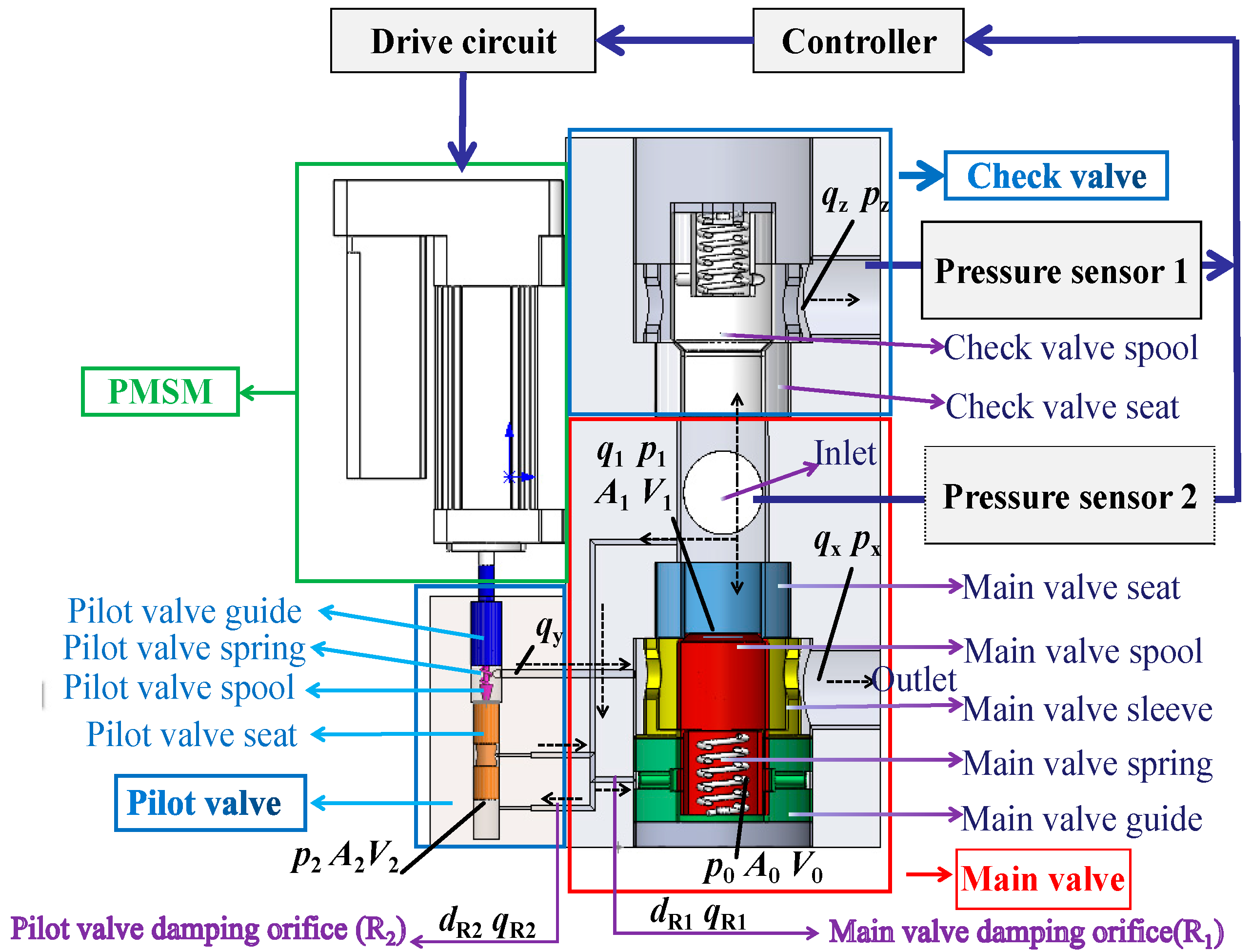
Aiming at the two core contradictions that the frequent opening and closing of the unloading valve during the frequent operation of the hydraulic bracket leads to pressure pulsation in the supply system, and that the static pressure regulation system of the relief valve makes the emulsion pumping station stay in the loading state for a long time and leads to the waste of energy, this paper puts forward a new scheme of multi-mode control according to the actual working conditions of the hydraulic bracket system. The core breakthrough of this scheme lies in the fact that, based on the high-precision position control method of the permanent magnet synchronous motor (PMSM), the spring pre-compression force of the pilot valve is dynamically adjusted through the threaded drive mechanism to achieve real-time closed-loop control of the outlet pressure of the pumping station. Accordingly, an engineering prototype of a high-pressure, high-flow digital pressure control valve for emulsion media was developed. A combination of simulation and experimental methods was used to study the control method, the dynamic characteristics of the digital pressure control valve, and the valve structure optimization. The objectives of this paper are to build a digital pressure control core element that meets the demand for intelligent development of mines and to reduce the unloading pressure pulsation under high-frequency action conditions and variable-load conditions of the hydraulic support group through a multi-mode cooperative control strategy; to realize the pressure supply of the pumping station according to the demand; and to reduce ineffective energy consumption.

2. Digital Pressure Control Valve Working Principle and Model

2.1. Working Principle of Digital Pressure Control Valve

The proposed digital pressure control valve is set at the outlet of the emulsion pumping station, and its pilot valve is driven by a PMSM. Different from the traditional unloading valve and relief valve working mechanisms, the proposed digital pressure control valve in this paper has both the traditional digital unloading valve and digital relief valve control modes, and adopts the authors’ previously proposed GRNN neural network, according to the specific working conditions of the system, to determine the multi-mode control scheme of the digital pressure control valve, selecting the overflow mode, the unloading mode, or the loading mode [30]. The digital pressure control valve performs the function of a relief valve or unloading valve in different operating modes, then determines the PMSM rotary position according to the selected operating mode and carries out feedback control.
The working principle of the digital pressure control valve designed in this paper is shown in Figure 1. The digital pressure control valve mainly consists of a main valve, a digital pilot valve, a check valve, a pressure sensor, and other components, in which the main stage part adopts a two-way cartridge valve structure, and the pilot stage part adopts a direct-acting relief valve with a PMSM controlling the spring pre-compression force. Pressure sensor 1 is installed at the outlet of the check valve to obtain the system pressure pz in real time, and pressure sensor 2 is installed at the inlet of the main valve to obtain the inlet pressure of the main valve p1 in real time. According to the comparison results between the actual pressure values (p1 and pz) and the set pressure threshold, as well as the liquid demand of the actual working conditions of the hydraulic support, the controller determines the linear increment of the PMSM to control the preload force of the pilot valve spring, achieving real-time regulation of the inlet pressure of the digital pressure control valve.

2.2. Description of the Model and Method

2.2.1. Mathematical Models of PMSM

Vector control is applied to the digital pressure control valve drive motor, and the three-phase stationary coordinate system (abc) is replaced by the synchronous rotating d–q coordinate system using the Clark transform and Park transform methods, which gives the voltage equation in the d–q rotating coordinate system:
u d = R s i d + d ψ d d t ω r ψ q u q = R s i q + d ψ q d t ω r ψ d
  • The magnetic chain equation is as follows:
    ψ d = L d i d + ψ f ψ q = L q i q
  • The torque equation is as follows:
    T e = 3 2 P n ( ψ d i q ψ q i d ) = 3 2 P n [ ψ f i q ( L d L q ) i d i q ]
  • The collation can be obtained by bringing Equation (1) into Equation (2):
    u d = R s i d + L d d i d d t ω r L q i q u q = R s i q + ω r ψ f + ω r L d i d + L q d i q d t
  • Equation of motion of the motor in the d–q coordinate system:
    T e T L = J d ω d t
    where Lq [H] and Ld [H] are stator d-axis and q-axis inductances; uq [V] and ud [V] are stator d-axis and q-axis voltages; iq [A] and id [A] are rotor d-axis and q-axis currents; iα [A] and iβ [A] are stator α-axis and β-axis currents; Ψ d [Wb] and Ψ q [Wb] are stator d-axis and q-axis magnetic chains; Te [N·m] is the electromagnetic torque; TL [N·m] is the load torque; Ψ f [Wb] is the rotor magnetic chain; and J is the inertia of rotation.

2.2.2. Design of Digital Pressure Control Valve Controller

The pilot drive motor of the digital pressure control valve adopts the field-oriented control (FOC) strategy to construct a three-closed-loop cascade structure of the current loop, speed loop, and position loop, achieving precise tracking control of the rotor position of the permanent magnet synchronous motor. The screw rotation of the drive motor drives the screw nut to perform linear motion, and the pre-compression force of the pilot spring is adjusted by changing the position of the adjusting sleeve and the pilot push rod. Considering the motor speed pulsation rate, frequency response, speed range characteristics, and other design requirements, in the vector control using the id = 0 control strategy, the current loop and speed loop are controlled using the PI algorithm [31]. In order to enable the motor rotation angle to precisely control the position of the pilot valve push rod, improve the response speed, stability, and robustness of the control system, and comprehensively consider the model strategies such as SMC, MPC, and Neural Network Control that rely on precise systems and training data, as well as the characteristics of SMC such as low computational complexity and no need for online optimization, it is more in line with the embedded real-time requirements of the pressure control valve. The position loop of the permanent magnet synchronous motor is controlled by a new approach-rate sliding mode control method.
In this paper, a new type of convergence rate is designed on the basis of the literature [32]:
s ˙ = k 1 x δ ε β + γ ε sgn ( s 1 ) k 2 | s | α sgn ( s )
where x is the state variable, k1 > 0, k2 > 0, 0 < α < 1, 0 < δ < 1, β > 0, γ > k1, and 0 < ε < 1.
The analysis of Equation (6) shows that when |s| > 1, the system trajectory is far from the sliding mode surface; a fast convergence term k 1 x σ ε β + γ ε + k 2 s α is used at this point to accelerate convergence. When |s| < 1, the system trajectory is close to the sliding mode surface and switches to the jitter suppression term k 2 s α to reduce the gain.
According to the determination condition of the stability of the control algorithm, the Lyapunov function V = s2/2 is established:
V ˙ = s s ˙ = s [ k 1 x δ ε β + γ ε sgn ( s 1 ) k 2 | s | α sgn ( s ) ] < 0
Thus, the new convergence rate suppresses jitter and ensures that the system is globally asymptotically stable and quickly converges to the sliding-mode surface.
Design of the system sliding-mode surface:
s = c ( t ) x 1 + x 2
Let iq = u and derive Equation (9) for the sliding-mode surface:
s ˙ = c ( t ) x ˙ 1 + x ˙ 2 = c ( t ) x 2 1 J ( 3 2 P n ψ f u T L B ω )
Find the control rate:
u = 1 D [ c ( t ) x 2 + b + B J ω + k 1 x δ ε β + γ ε sgn ( s 1 ) + k 2 | s | α sgn ( s ) ]

2.3. Establishment of Digital Pressure Control Valve Model

2.3.1. Establishment of Pilot Valve Drive System Simulation Model

The pilot drive system of the digital pressure control valve adopts a PMSM, motor screw, screw nut, and adjusting sleeve as the core drive mechanism. When establishing the mathematical model of the drive system, the motor screw is connected to the screw nut, ignoring the gap between the two. Limiting the rotation of the adjusting sleeve to achieve the motor screw rotation drives the axial movement of the adjusting sleeve to push the pilot actuator, ignoring the elastic deformation of the servomotor and the screw coupling [33]. The entire electrical–mechanical conversion system input is the PMSM angle θm, and the axial displacement of the adjusting sleeve y0 as the output.
The relationship between the angular displacement θM of the screw output and the axial displacement y0 of the adjusting sleeve is derived from the equation of motion of the screw transfer:
y o ( t ) = i θ M ( t )
where p is the screw nut lead, and i = p / 2 π .
Neglecting the elastic deformation at the coupling of the drive motor and the screw, the output torque of the motor is the input torque of the screw:
T L ( t ) = J L d 2 θ M ( t ) d t 2 + B L d θ M ( t ) d t + T g ( t )
Within the range of elastic variation:
T L ( t ) = K L [ θ m ( t ) θ M ( t ) ]
where TL(t) [N·m] is the torque of the lead screw; Jm [kg·m2] is the moment of inertia of the lead screw; Bm is the viscous damping coefficient of the lead screw; θm [rad] is the input angular displacement for the lead screw; θM [rad] is the output angular displacement for the lead screw; Tg(t) [N·m] is the axial load disturbance torque of the lead screw; and Km [N·m/rad] is the torsional stiffness of the lead screw.
When the load disturbance torque Tg = 0, by simultaneously solving Equations (12) and (13) and performing the Laplace transform, the transfer function is obtained as follows:
θ M ( s ) = K L θ m ( s ) J L s 2 + B L s + K L
Substituting Equation (11) into Equation (14) gives the ball screw transfer function as follows:
y 0 ( s ) θ m ( s ) = i K L J L s 2 + B L s + K L
From the screw transfer function, the ball screw transfer function block diagram can be obtained, as shown in Figure 2.
The simulation model of the digital pressure control valve drive system is built in Matlab/Simulink, and the control block diagram of the drive system is shown in Figure 3. The main performance parameters of the PMSM are shown in Table 1.

2.3.2. Co-Simulation Simulation Model Building

In this paper, the co-simulation of AMESim and Simulink is used. The physical modelling of the pressure control valve was carried out by AMESim software (Simcenter Amesim 2020.1), and the simulation modeling of the drive control system of the digital pressure control valve was carried out using Simulink software (MATLAB R2018B), respectively, and the co-simulation of the system was achieved by using the data interface. The co-simulation model of the digital pressure control valve is shown in Figure 4.
Figure 4a is a simulation model for testing the working performance of the digital pressure control valve under the unloading and loading conditions of the pumping station. In the figure, the input signal of the state machine module is the system pressure, and after the state machine determines whether the pressure control valve is loaded or unloaded, the output signal is the angular position of the drive motor corresponding to this state. The Simulink control subsystem control principle is shown in Figure 3, and the input variable of the subsystem is the desired turn angle of the drive motor matched to the demand of the whole hydraulic system at this moment. Figure 4b is the simulation model for testing the working performance of the digital pressure control valve under the liquid supply condition of the pumping station. Different from Figure 4a, the input signal of the Simulink module is a constant value.
In order to avoid the interference of redundant factors, the following simplifications were made when building the AMESim simulation model.
  • The bulk modulus and absolute viscosity of the emulsion are constants.
  • The emulsion is an incompressible liquid, and its density is independent of temperature.
  • The leakage of the components in the system is not considered.
  • Assume that the outlet pressure of the pressure control valve is atmospheric pressure.
The rated working pressure of the emulsion pump is 31.5 MPa, the rated flow rate is 200 L/min, and the working medium is emulsion. Specific simulation parameters are set as shown in Table 2.

3. Experimental Verification

Based on the Simulink/AMESim co-simulation model established in the previous section, this paper compares the simulation results and experimental data under the overflow working condition. The experiment system and data used as the comparison benchmark are derived from previous studies [
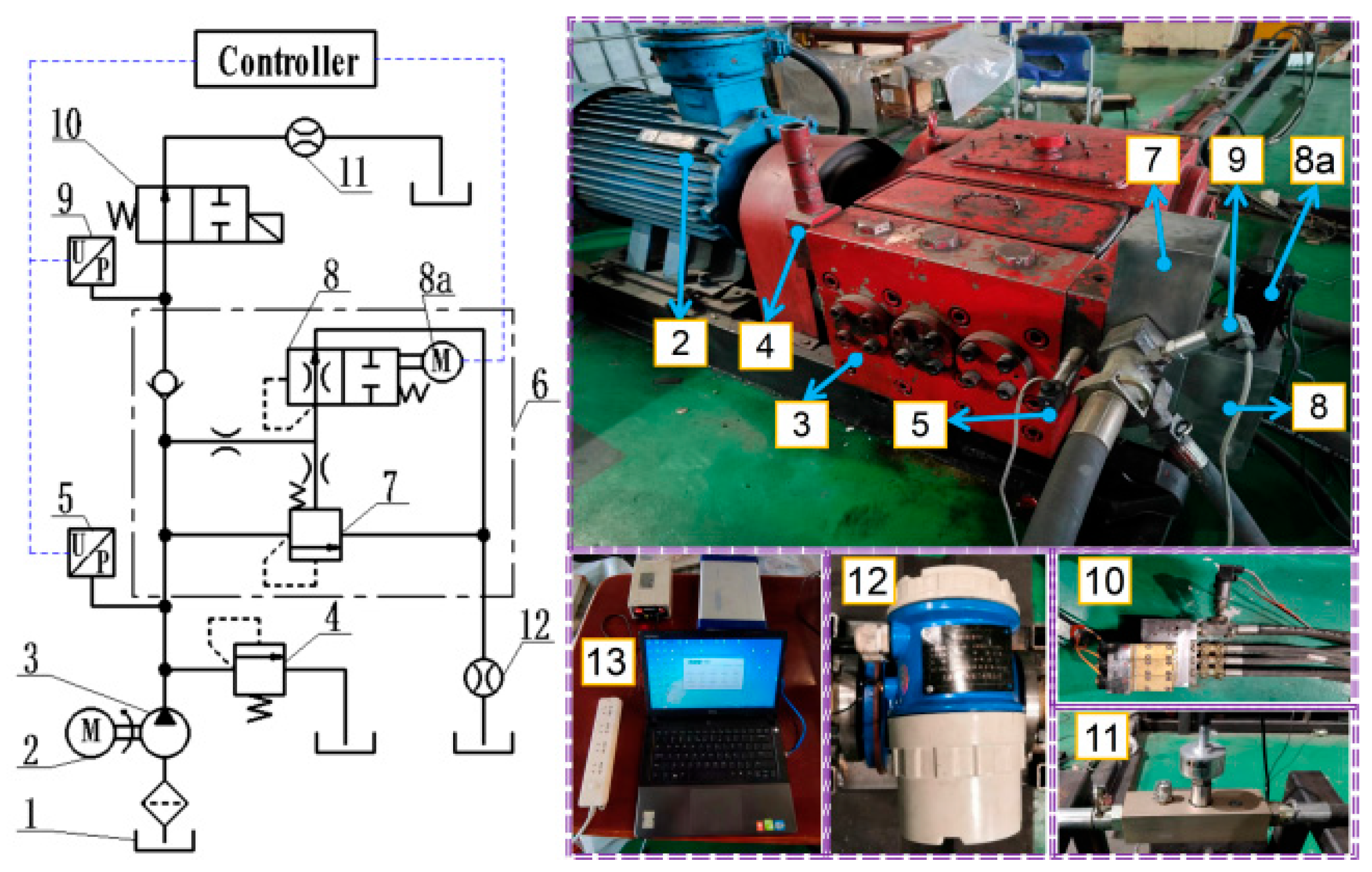
30]. This citation aims to verify the accuracy of this simulation model and lay the foundation for the subsequent proposed control methods and structural parameter optimization research. The experiment equipment and principle are shown in Figure 5.
Before the operation test, the directional valve (10) is powered off in the left position, and the emulsion pump (3) is started. When the emulsion pump operates stably, the spring pre-compression of the pilot valve (8) is adjusted to 0 mm. Then, the reversing valve (10) is energized, and the emulsion flows back to the emulsion tank through the pressure control valve (6), putting the pumping station in the unloading state.
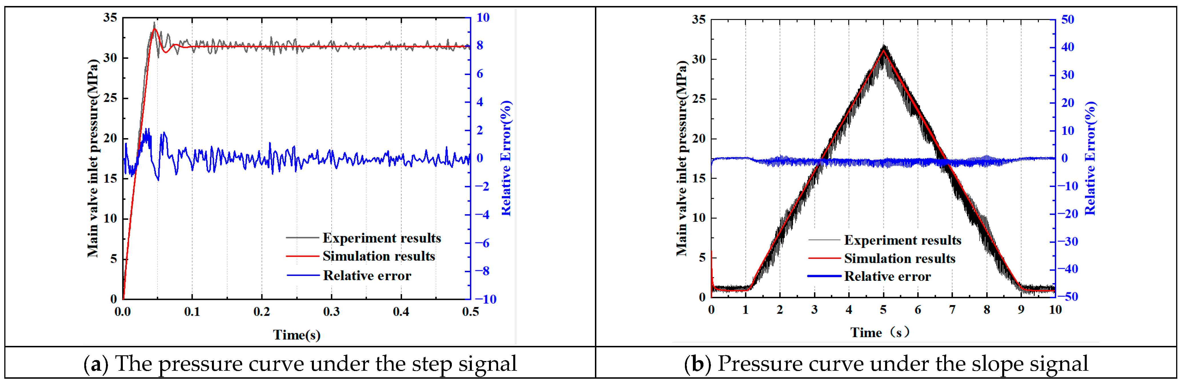
At the beginning of the test, the controller sends a pulse signal to the drive motor (8a) to change the adjusted pressure of the pilot valve (8) through the angle of the drive motor and collects the main valve inlet pressure through the pressure sensor (5). In order to test the pressure response characteristics of the main valve inlet under different input signals, step and slope signals were output to the digital pressure control valve. Figure 6a,b, respectively, shows the test and simulation results for those signals.
Figure 6a compares the pressure values obtained from the test and simulation of the digital pressure control valve under the step signal. Because the delay characteristics of the motor were ignored in the simulation process, the response speed obtained from the experiment was slower than the result obtained from the simulation. The test result values fluctuated around the steady-state pressure. This is because there was flow pulsation in the plunger pump during the test, but the influence of the flow pulsation of the hydraulic pump was not considered in the simulation process. It can be seen from Figure 6a that the relative error between the simulation data and the test results is within ±2.6%.
Figure 6b compares the pressure values obtained from the test and simulation of the digital pressure control valve at the ramp signal. The relative error between the simulated data and the test results is within ±4.7%. The test results show good consistency with the simulation results, verifying the validity of the simulation model.

4. Results and Discussion

4.1. Simulation Study of PMSM

4.1.1. Comparative Simulation Study of Different Control Strategies

Since the rotor of the drive motor rotates the lead screw nut, the rotation angle is converted into the axial displacement of the pilot push rod by adjusting the sleeve, thereby controlling the opening pressure of the pilot valve. Therefore, the angular position response characteristics of the drive motor directly determine the quality of the dynamic response characteristics of the digital pressure control valve. In order to verify the effectiveness of the proposed new convergence rate sliding mode control strategy, respectively, simulation studies were conducted on the position response and position tracking performance of the PI controller and the new approach-rate sliding mode controller for the position control system of the drive motor. The simulation results of the waveform are shown in Figure 7.
As shown in Figure 7, the angle step signal is input to the drive motor at the moment of 0 s, and the motor is started under the no-load condition. By comparing the control performance of the position control system of the drive motor with the PI controller and the sliding film controller, it can be seen that the response time of the drive motor under the PI controller is approximately 0.045 s. Under the new approach-rate sliding mode controller, the response time is approximately 0.013 s. The motor responds faster. The response time to reach the target position is shortened by approximately 71%, and the steady-state error can basically be ignored after reaching the target position.
Further testing of the position tracking performance of the digital pressure control valve drive system was conducted with an input amplitude of 1 rad sinusoidal signal. Figure 7b shows that the phase lag between the new convergence rate sliding mode controller and the input signal curve is only 0.025 rad, and, compared with the tracking accuracy of the PI position control, the position control system of the new convergence rate sliding mode controller is also greatly improved in tracking accuracy.
In summary, compared with the PI position control, the drive motor based on the new convergence rate sliding mode control method has a faster response speed and reaches the target position in a shorter time. This verifies that the new convergence rate sliding mode control proposed in this paper can improve the dynamic and static performance of the digital pressure control valve drive system.

4.1.2. Simulation Study of Dynamic Characteristics

Aiming at the proposed new convergence rate sliding mode control method for the position control system of the drive motor, a further simulation study was carried out on the digital pressure control valve drive system. In order to simulate the application working condition of the drive motor under variable load during the starting process with load, a sudden change of load was applied to the drive motor during the simulation process to study the response characteristics of the motor under variable load conditions.
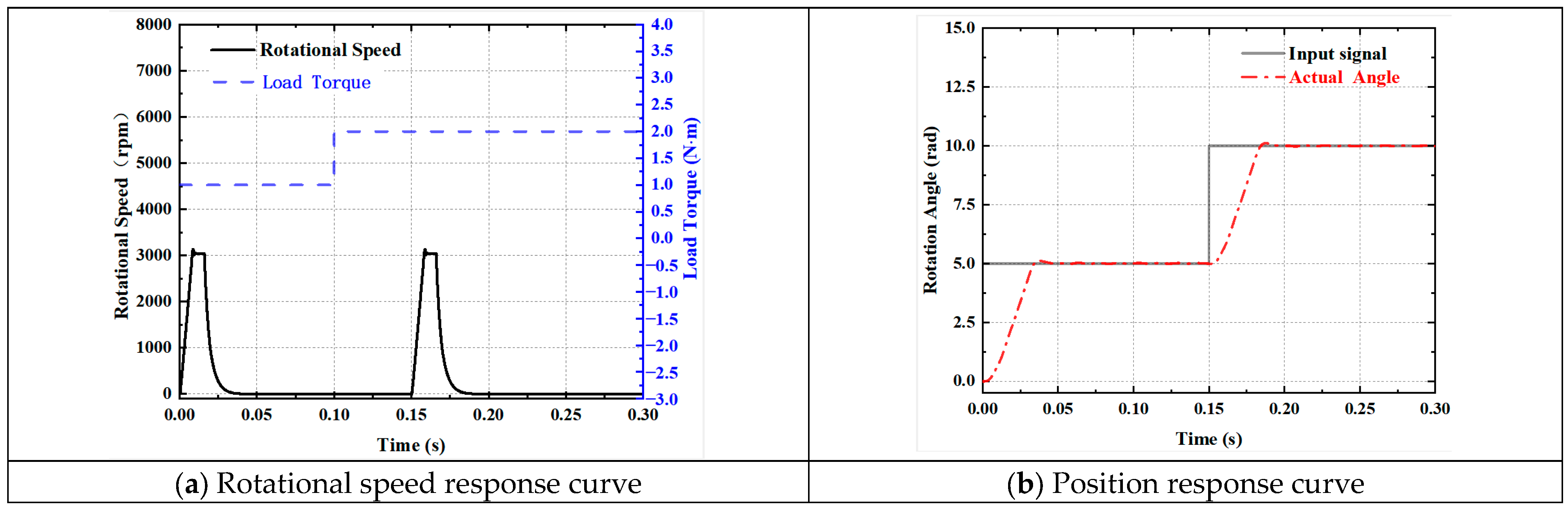
(1) Speed Response Characteristics under Variable Load Conditions
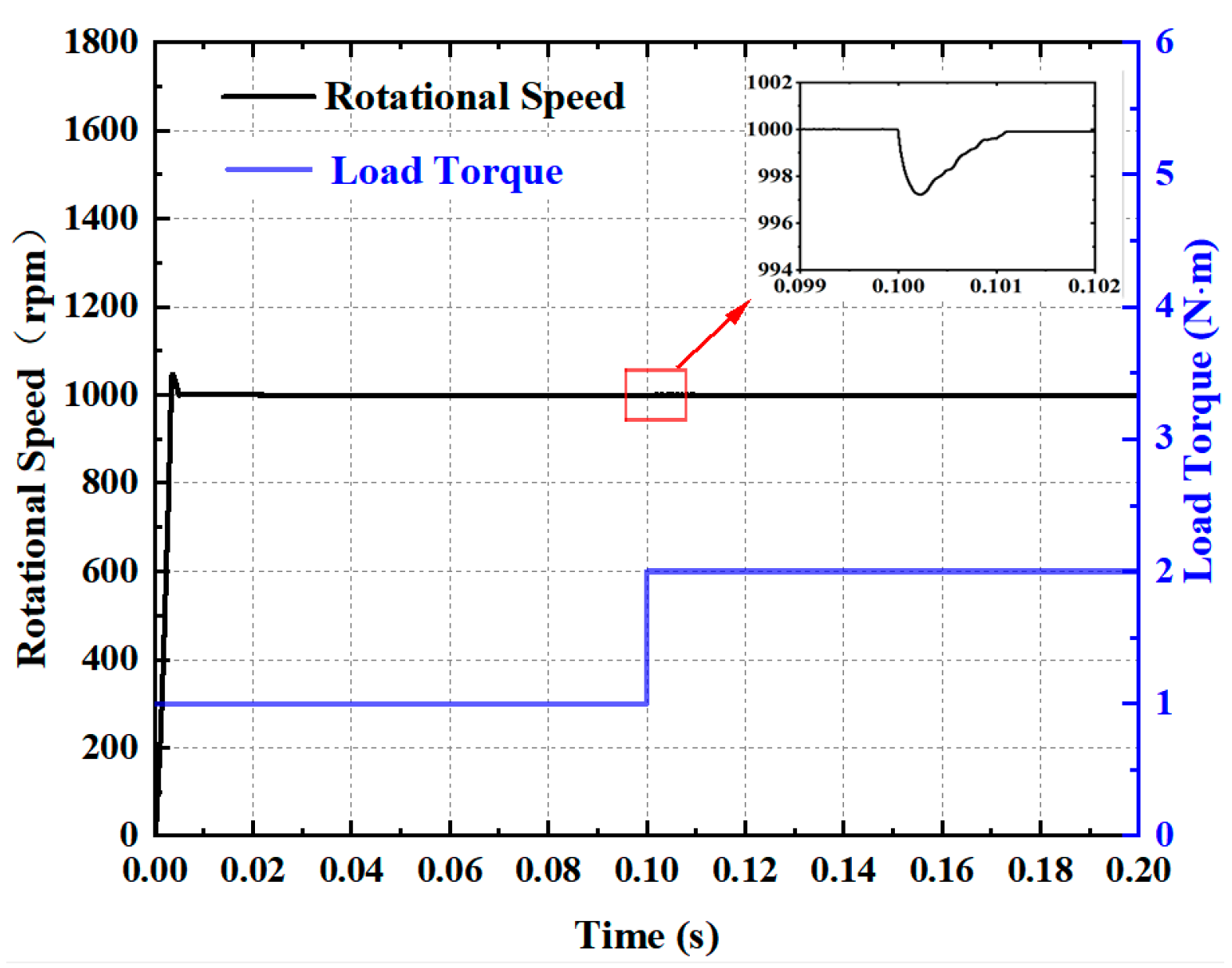
To study the effect of load change on rotational speed alone, the output of the position loop controller is not considered to change, and the input speed command of the speed loop is given as 1000 rpm. The load torque of the motor is set to be 1 N·m for the time period of 0~0.1 s and 2 N·m for the time period of 0.1~0.2 s to simulate the load change of the motor during loaded startup and operation, respectively.
As shown in Figure 8, the drive motor quickly tracks the reference speed during acceleration and sudden load change. In the 0~0.1 s start-up phase with load, the motor speed stabilizes at 1000 rpm after 0.005 s, instantly reaching the steady-state speed, and the speed response overshoot is less than 6%. At the moment of 0.1 s, there is a transient fluctuation of small amplitude in the motor speed due to the load mutation, and it recovers to the reference speed after about 0.0013 s, with the maximum fluctuation amplitude being only 3 rpm. At the moment of 0.1 s, the motor speed fluctuates briefly due to the sudden change of load and returns to the reference speed after about 0.0013 s. The maximum fluctuation amplitude is only 3 rpm, which indicates that the motor speed has strong robustness when it is disturbed by the external load.
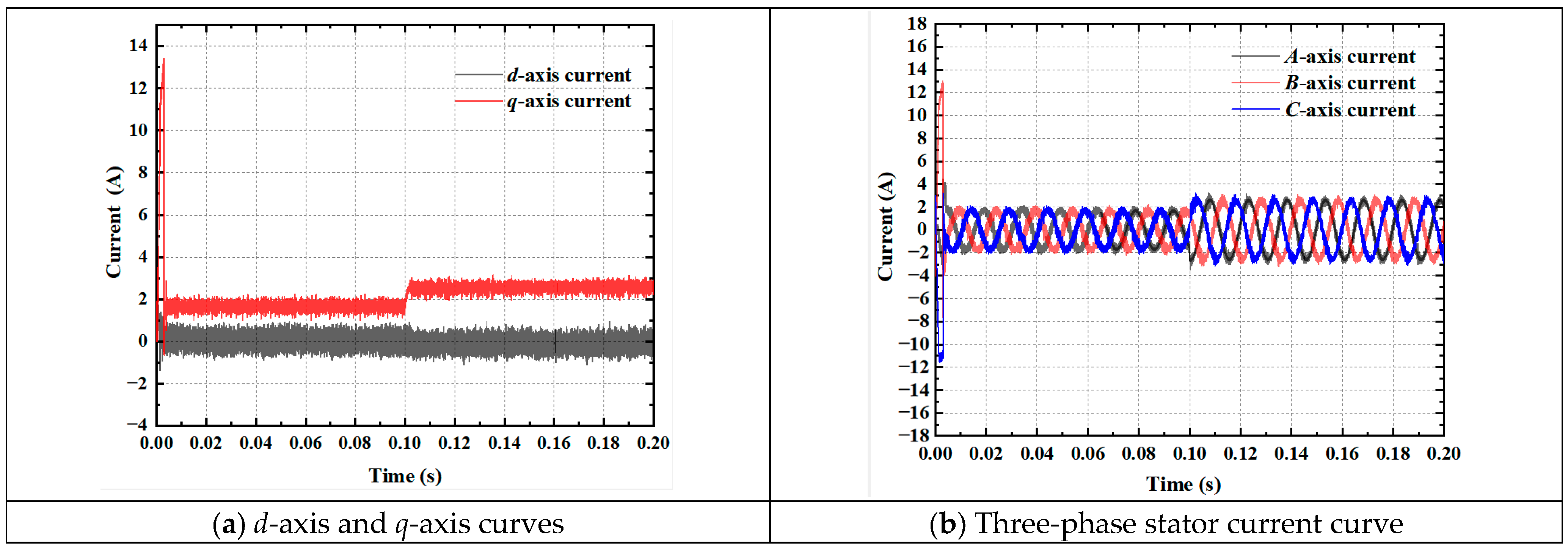
As shown in Figure 9a, the q-axis current increases instantaneously during acceleration of the drive motor, and since the electromagnetic torque is positively correlated with the value of iq, the larger instantaneous electromagnetic torque overcomes the load so that the motor speed can reach the target speed quickly. At the stage when the motor speed is stabilized at 1000 rpm, the q-axis current increases from 1.7 A to 2.5 A to overcome the load change due to the sudden change in load torque at 0.1 s. The q-axis and d-axis currents remain stable throughout the process, indicating excellent decoupling performance. From Figure 9b, it can be seen that the stator three-phase currents are sinusoidal throughout the variable load operation, which indicates that the parameters of the current loop and speed loop PI controllers are reasonable after parameter adjustment.
(2) Position Response Characteristics Under Variable Load Conditions
Considering the actual working conditions of the drive motor, the motor load torque is set to be 1 N·m in the time period from 0 to 0.1 s to simulate the start-up process of the drive motor under load. A sudden change in load torque of 2 N·m is applied at the time of 0.1 s to simulate the external load change process of the drive motor during loaded operation. The displacement response characteristics of the drive motor during start-up and operation under load are investigated by the sudden change in external load.
As shown in Figure 10, the motor speed is almost unaffected by the load change when the load torque is suddenly increased at 0.1 s. Meanwhile, in terms of position control performance, the motor completes positioning in the shortest time, and the time for the motor rotor to stabilize the position response curve to the target position does not change under different load conditions, which is highly robust.

4.2. Simulation of Unloading–Loading Characteristics of the Digital Pressure Control Valve

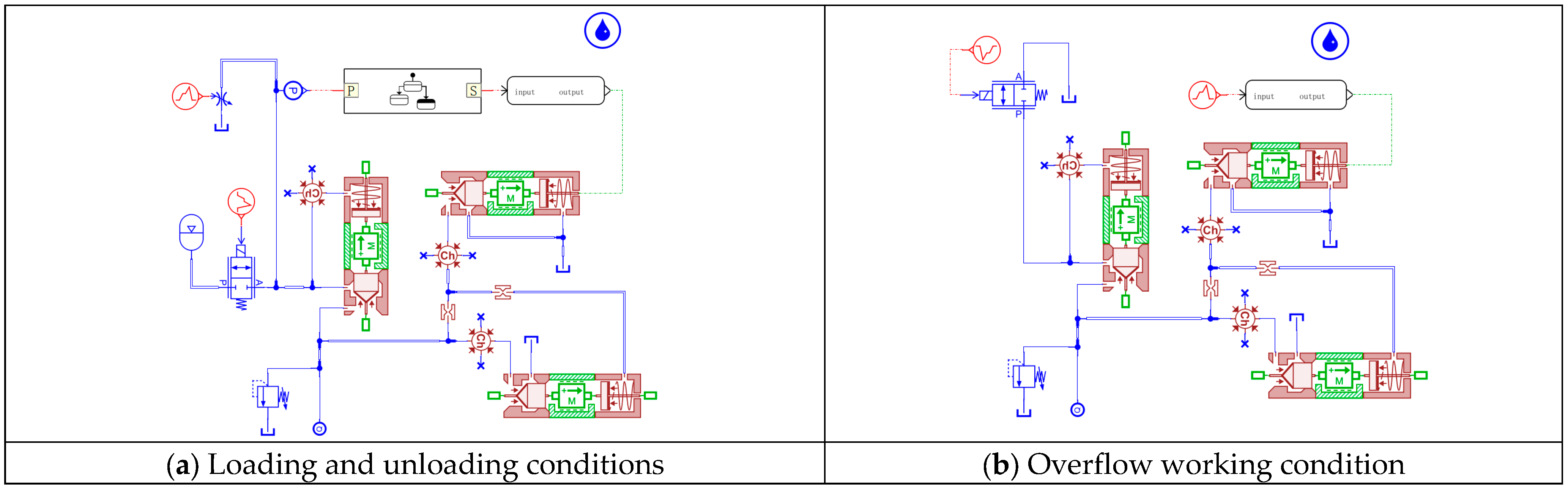
In order to study the working performance of the digital pressure control valve under the unloading and loading conditions of the pumping station (the pressure control valve functions as the unloading valve), the response characteristics of the main valve inlet and the system pressure are studied. According to the simulation model constructed in Figure 4a, the external throttle valve simulates the continuous small amount of liquid used in the liquid supply system in order to achieve the simulation of the continuous dynamic working process of the liquid supply system. The simulation results of the dynamic characteristics of the opening and closing process of the digital pressure regulator valve are shown in Figure 11.
Figure 11 shows the digital pressure regulator valve unloading–loading process inlet pressure and system pressure diagram. In the beginning stage, the main valve is in the closed state, the emulsion pumping station is in the loading state, and the system pressure rises rapidly. When the system pressure rises to the accumulator filling pressure, due to the influence of the accumulator, the hydraulic system pressure rises more slowly. When the system pressure reaches the unloading pressure, the digital pressure regulating valve opens, and the emulsion pumping station is unloaded. During the unloading stage, the value of the emulsion pump outlet pressure (the main valve inlet pressure) stays stable at 0.485 MPa, which effectively avoids unnecessary energy consumption and optimizes the energy utilization efficiency. Due to continuous leakage through the throttle valve during the unloading stage, the hydraulic system pressure drops to the loading pressure limit, the pressure regulating valve closes, the pump station re-enters the loading state, and the cycle repeats. The instant pressure impact of the entire process of the digital pressure regulator valve response speed, opening, and closing is small.

4.3. Simulation of Operating Characteristics of the Digital Pressure Control Valve in Overflow Condition

In order to study the operating performance of the digital pressure control valve in the relief condition (the pressure control valve performs the function of a relief valve), the pressure response characteristics of the main valve inlet will be investigated below.
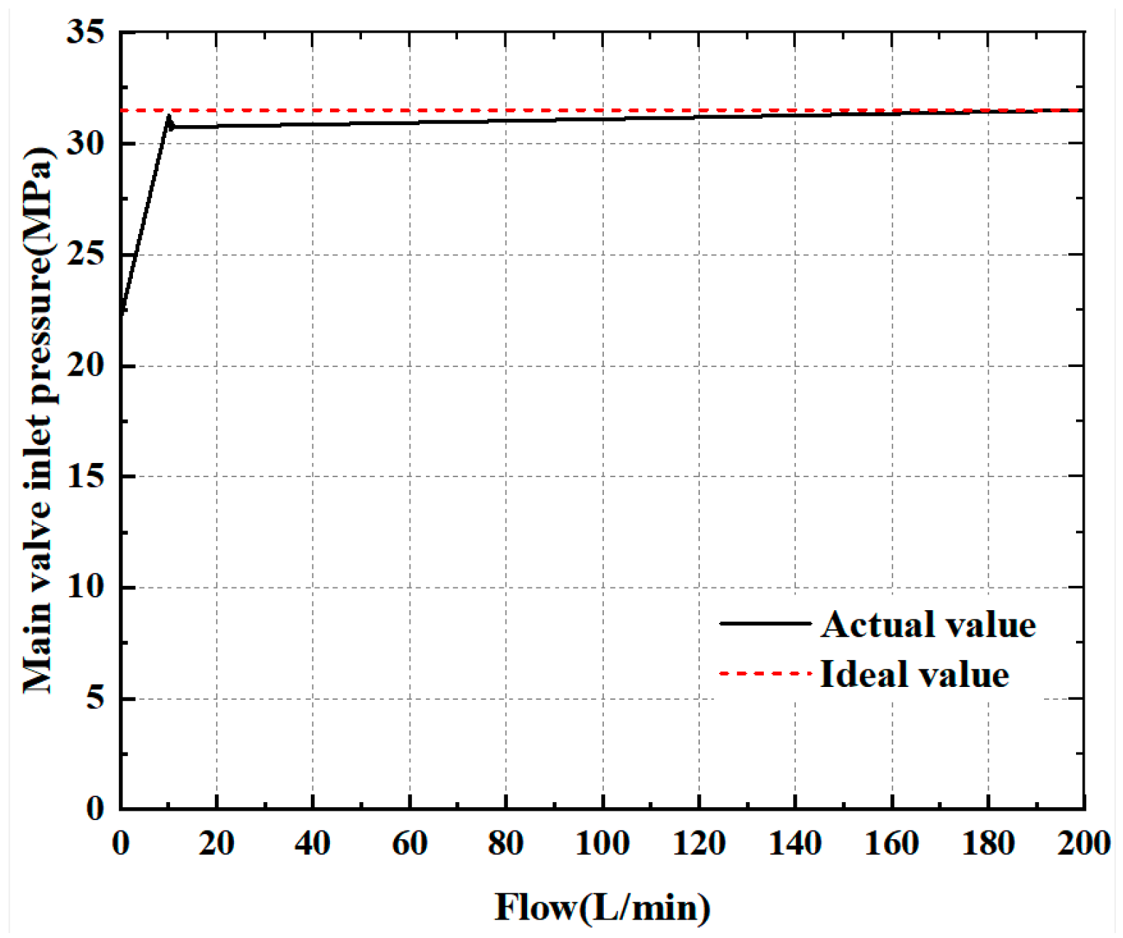
Figure 12 shows the static characteristics of the main valve inlet of the digital pressure control valve. According to the simulation model built in Figure 4b, the directional valve is set to the right position in advance, the output flow rate of the pump station is 0~200 L/min, and the simulation time is 10 s. The simulation results under the condition of an unchanged spring adjustment preload of the pilot valve are processed, and the obtained static characteristic curve is shown in Figure 12.
As can be seen from the simulation results, when the inlet pressure reaches 22.41 MPa, the pilot valve opens, the digital pressure control valve begins to produce overflow, and the pressure, with the increase in overflow flow rate, rapidly rises to 30.69 MPa. There is a slight fluctuation, and the pressure curve tends to flatten out. When the overflow flow reaches 200 L/min, the main valve port pressure is 31.51 MPa, which basically coincides with the ideal rated pressure value, indicating that the rated operating pressure meets the design requirements.
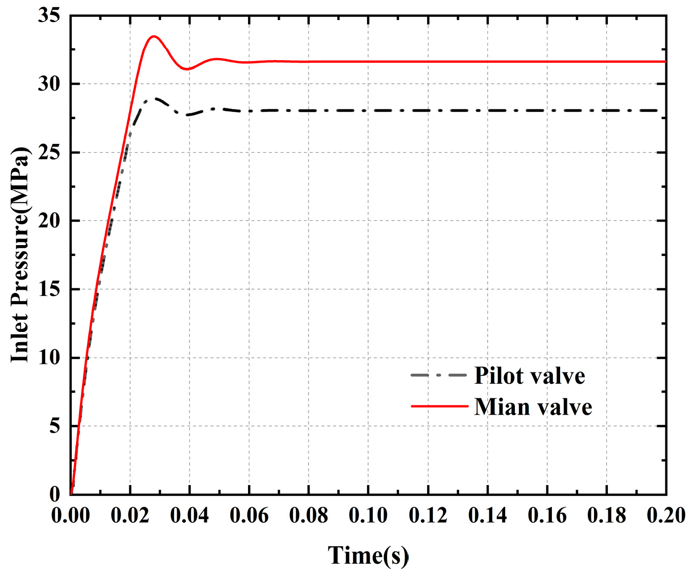
The static characteristics of the main valve inlet of the pressure control valve are investigated. According to the simulation model built in Figure 4b, the directional valve is set to the right position in advance, the output flow rate of the pump station is 200 L/min, the simulation results under the condition of an unchanged spring-adjusted preload of the pilot valve are processed, and the simulation obtains the dynamic response curve of the pressure inlet of the pilot part and the main valve part of the pressure control valve, as shown in Figure 13.
From the simulation results, it can be seen that the main valve inlet pressure reaches a stable value at 76.2 ms, the stable value of the pressure is 31.51 MPa, the overshooting amount is 6.3%, and the response time is 28.4 ms. The pilot valve inlet pressure reaches a stable value at 61.1 ms, the stable value is 27.86 MPa, the overshooting amount is 3.2%, and the response time is 27.3 ms. The designed digital pressure control valve pilot spool and main spool opening time interval is short, the inlet pressure is stable, the overshooting amount is small, the stabilisation time is short, and it has good dynamic response characteristics.

5. Structure Optimization

Through the above simulation analysis of the structural parameters of the pressure control valve on the dynamic response characteristics of the impact of the integrated factors, an appropriate range of parameters is selected. Through the optimization function in AMESim, genetic algorithms are used to optimize the structural parameters of the valve. Genetic algorithms for specific parameter selection are shown in Table 3, and the optimized structure of the pressure control valve parameters is shown in Table 4.
The comparison of the optimization results of the structural parameters of the pressure control valve with the initial results is shown in Figure 14, from which it can be seen that after the optimisation of the structural parameters of the pressure control valve, the pressure reaches a stable value at 44.8 ms, with a stabilised pressure of 31.5 MPa, and the response time is 20.1 ms, which is a shortening of 8.3 ms. The pressure overshooting amount is 4.1%, which is a reduction of 2.2%.

6. Conclusions

Aiming at the pressure pulsation and energy waste of the existing unloading valves and relief valves in the underground working face, this paper puts forward a multi-mode control scheme according to the actual working conditions of the hydraulic bracket system, using a new convergence rate sliding film position control method to control PMSM to control the pilot valve in order to regulate the outlet pressure of the pump station in real time, and develops a new type of digital pressure control valve prototype for the emulsified liquid medium under high-pressure and large-flow conditions.
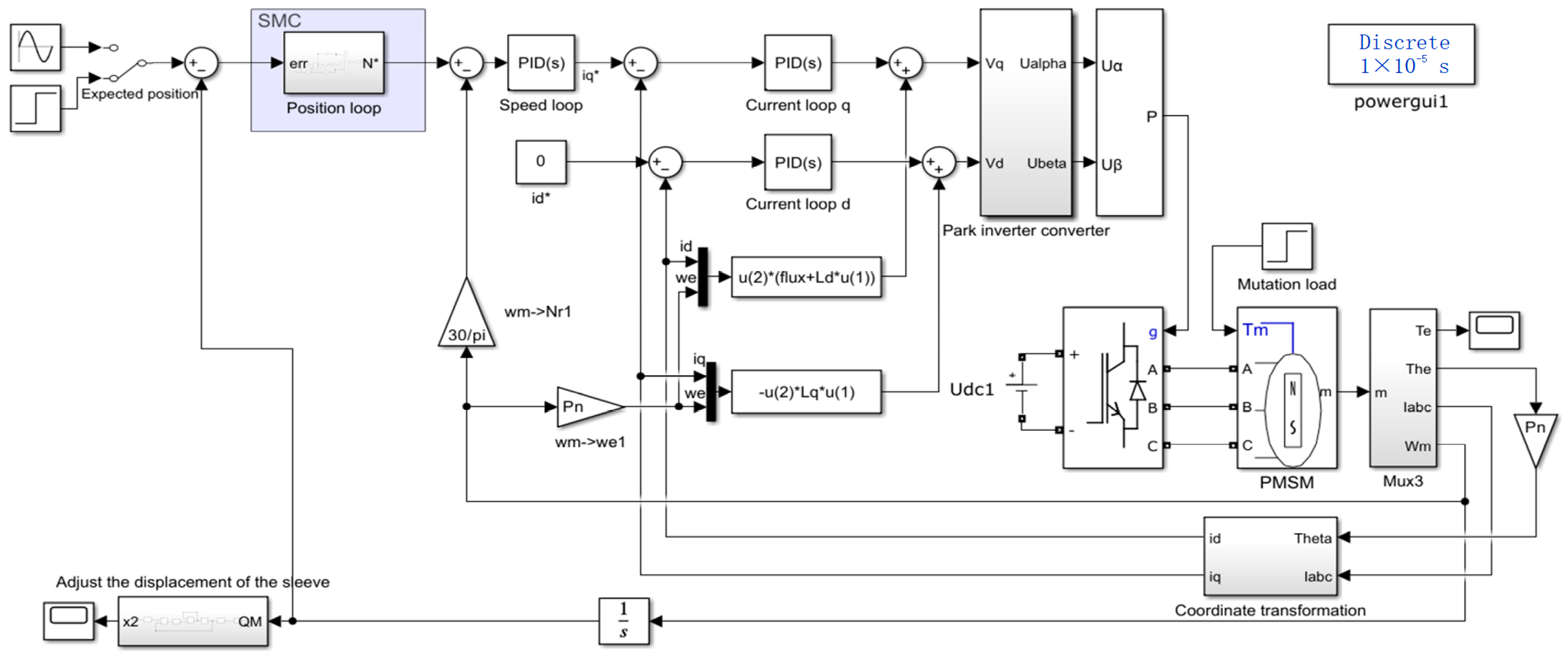
The drive scheme of the digital pressure control valve and the controller of the drive system were designed, and a Simulink simulation model was established. The pilot drive motor adopted a three-closed-loop control system, and the control of the position loop was optimized. Simulation studies were conducted respectively on the position response and position tracking performance of the drive motor position control system by the PI controller and the proposed new approach-rate sliding mode controller. The results show that the response time to reach the target position under the new approach-rate sliding mode controller is approximately 0.013 s, which is shortened by about 71% compared with the PI control. Moreover, it has excellent tracking performance, and the phase lag with the input signal curve is only 0.025 rad. Further simulation studies were conducted on the response characteristics of the drive motor during the start-up process with load and under variable load conditions. The results show that the proposed new approach-rate sliding mode control designed can improve the response characteristics of the drive system. The time for the motor speed to stabilize at 1000 rpm is 0.005 s, and the overshoot is less than 6%. At the moment of sudden load change, the motor speed can recover to the reference speed after 0.0013 s, and the maximum fluctuation amplitude is only 3 rpm, which indicates strong robustness.
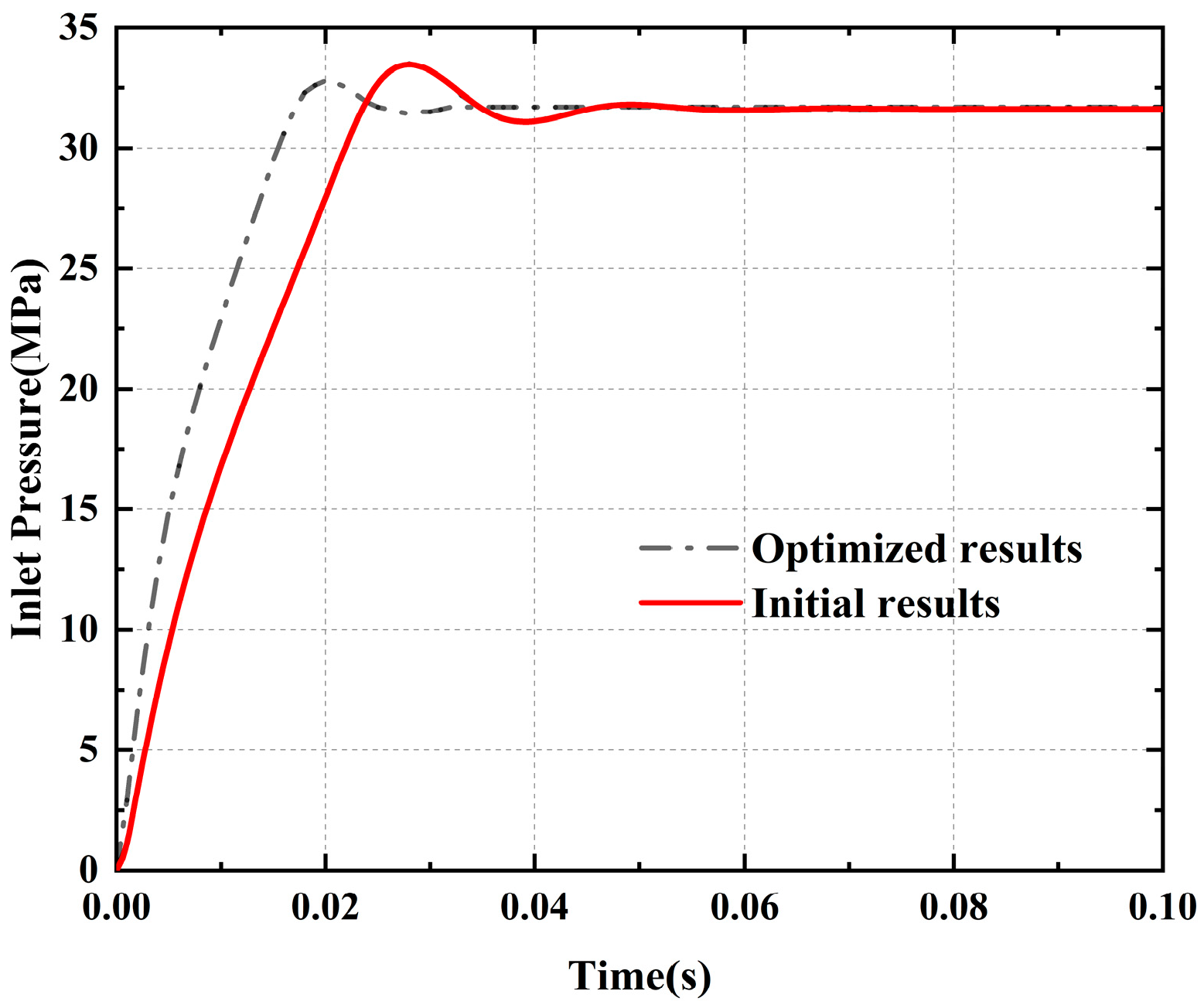
Based on the Simulink simulation model of the drive system controller, the AMESim/Simulink joint simulation model of the digital pressure control valve was established, and the correctness of the simulation model was verified through experimental analysis. The static characteristics, dynamic characteristics, and other aspects of the digital pressure control valve were analyzed through the joint simulation of AMESim/Simulink. The results show that the stabilization time of the inlet pressure of the main valve is 76.2 ms, the pressure stabilization value is 31.51 MPa, and the overshoot is 6.3%. The overall working performance of the designed digital pressure control valve is good. Moreover, the main structural parameters of the valve were optimized through the genetic algorithm. The pressure stabilization time was 44.8 ms, and the pressure overdraft was 4.1%. The optimized model has better performance than the one before optimization.

Author Contributions

Conceptualization, P.X. and Z.K.; methodology, P.X., J.Z. and Z.K.; software, P.X.; validation, P.X.; formal analysis, P.X.; investigation, P.X.; resources, Z.K. and J.Z.; data curation, P.X.; writing—original draft preparation, P.X.; writing—review and editing, P.X., J.Z. and Z.K.; visualization, Z.K.; supervision, Z.K.; project administration, J.Z. and Z.K.; funding acquisition, J.Z. and Z.K. All authors have read and agreed to the published version of the manuscript.

Funding

This work was supported by the National Key Research and Development Program of China (2024YFB4711001)—“All-Weather Multi-Modal Fusion Perception for Shovel-Loading Robots in Complex Working Conditions”; the National Natural Science Foundation of China (U1910212).

Data Availability Statement

The original contributions presented in this study are included in the article. Further inquiries can be directed to the corresponding authors.

Acknowledgments

The authors appreciate the Shanxi Boshitong Electromechanical Hydraulic Co., Ltd. for providing the test site.

Conflicts of Interest

The authors declare no conflicts of interest.

References

  1. Lim, G.H.; Chua, P.S.K.; He, Y.B. Modern Water Hydraulics—The New Energy-Transmission Technology in Fluid Power. Appl. Energy 2003, 76, 239–246. [Google Scholar] [CrossRef]
  2. Majdic, F.; Pezdirnik, J.; Kalin, M. An Analytical Comparison of Hydraulic Systems Based on Water and on Oil. Proc. JFPS Int. Symp. Fluid Power 2008, 2008, 679–684. [Google Scholar] [CrossRef]
  3. Lv, Q. Design and research of digital unloading valve for hydraulic support of comprehensive mining face. Autom. Appl. 2023, 64, 122–124. [Google Scholar]
  4. Xia, Y.; Lv, S.; Li, J. Development of cut-off unloading valve for hydraulic support. Coal Technol. 2022, 41, 214–215. [Google Scholar] [CrossRef]
  5. Dai, P. Experimental and Applied Research on Static and Dynamic Characteristics of Electromagnetic Unloading Constant Pressure Variable Pump. Master’s Thesis, China University of Petroleum, Beijing, China, 2007. [Google Scholar]
  6. Chen, C.-P.; Chiang, M.-H. Development of Proportional Pressure Control Valve for Hydraulic Braking Actuator of Automobile ABS. Appl. Sci. 2018, 8, 639. [Google Scholar] [CrossRef]
  7. Wan, L.; Dai, H.; Zeng, Q.; Lu, Z.; Sun, Z.; Tian, M.; Lu, Y. Characteristic Analysis of Digital Emulsion Relief Valve Based on the Hydraulic Loading System. Shock Vib. 2020, 2020, 8866919. [Google Scholar] [CrossRef]
  8. Yang, S.-J.; Jin, C.-B.; Hu, J.-B. Study on the PWM digital proportional relief valve. Chin. Hydraul. Pneum. 2005, 3, 46–49. [Google Scholar]
  9. Tian, C.J.; Zhang, Y.W.; Wang, J.; Ru, G.F.; Yan, J.Q. Design and performance analysis of digital pressure relief valve of water-based hydraulic. Appl. Mech. Mater. 2013, 387, 369–373. [Google Scholar]
  10. Zhang, Q.; Kong, X.; Yu, B.; Ba, K.; Jin, Z.; Kang, Y. Review and Development Trend of Digital Hydraulic Technology. Appl. Sci. 2020, 10, 579. [Google Scholar] [CrossRef]
  11. Liu, X.; Yang, X.; Li, S.; Liang, D. Design, Modelling, and Analysis of a Capacitive Reservoir Based PWM Digital Circuit of Electro-Hydraulic Proportional Valve. Appl. Sci. 2023, 13, 8825. [Google Scholar] [CrossRef]
  12. Wei, W.; Ren, W. Design and realisation of automatic unloading system for emulsion pumping station. Coal Eng. 2007, 8, 20–21. [Google Scholar]
  13. Xie, S. Research and Analysis of High-Pressure and High-Flow Cartridge Type Proportional Unloading Valve. Master’s Thesis, China University of Mining and Technology, Xuzhou, China, 2021. [Google Scholar] [CrossRef]
  14. Jiang, T.; Tan, J.; Si, Y.; Sun, K. Experimental study on unloading law of high-pressure and high-flow hydraulic system. Forg. Press. Technol. 2012, 37, 80–83. [Google Scholar]
  15. Guo, K. Research on Pressure Characteristics of Intelligent Fluid Supply System for Hydraulic Support. Master’s Thesis, Taiyuan University of Technology, Taiyuan, China, 2022. [Google Scholar] [CrossRef]
  16. Wang, C.; Hao, F.; He, T.; Zhou, D.; Yang, L.; Ma, D.; Zhang, J. Parameter optimization for dynamic performance of a new hydraulic relief valve in coal mine. In Proceedings of the CSAA/IET International Conference on Aircraft Utility Systems (AUS 2018), Guiyang, China, 19–22 June 2018; pp. 297–302. [Google Scholar]
  17. Jia, W.; Yin, C.; Hao, F.; Li, G.; Fan, X. Dynamic Characteristics and Stability Analysis of Conical Relief Valve. Mechanika 2019, 25, 25–31. [Google Scholar] [CrossRef]
  18. Zeng, Q.-L.; Tian, M.-Q.; Wan, L.-R.; Song, G.-H.; Liu, M.; Zhu, G.-S.; Wu, J.-H. Characteristic Analysis of Digital Large Flow Emulsion Relief Valve. Math. Probl. Eng. 2020, 18, 5820812. [Google Scholar] [CrossRef]
  19. Sang, C.J.; Kang, J.H. Orifice design of a pilot-operated pressure relief valve. J. Press. Vessel. Technol. 2017, 139, 031601. [Google Scholar]
  20. Hao, Q.H.; Wu, W.R.; Liang, X.J.; Liu, Z. Effects of Structure Parameters on Abnormal Opening of Pilot-Operated Relief Valve Under Alternating Pressure. IEEE Access 2019, 7, 33932–33942. [Google Scholar] [CrossRef]
  21. Shin, Y.C. Static and dynamic characteristics of a two stage pilot relief valve. J. Dyn. Syst. Meas. Control 1991, 113, 280–288. [Google Scholar] [CrossRef]
  22. Deng, Y.-J.; Liu, Z.-W. Optimal design of pilot proportional relief valve’s structural parameters in giant forging hydraulic press. In Proceedings of the International Symposium on Digital Electronics and Applications (ISDEA), Sanya, China, 6–7 January 2012; pp. 412–416. [Google Scholar]
  23. Liu, X.; He, X.; Luo, L.; Luo, X. Simulation on the Dynamic Characteristics of an Electromagnetic Relief Valve with High Pressure and Large Flow Rate. Appl. Mech. Mater. 2013, 303, 1786–1789. [Google Scholar] [CrossRef]
  24. Zhang, J.; Xue, X.; Kou, C.; Yao, J.; Kong, X. Modeling of DN63 Displacement-follower Ultra High Pressure Proportional Cartridge Valves. China Mech. Eng. 2019, 30, 2424. [Google Scholar]
  25. Bossard, J.; Reich, A.; DiMeo, A. Dynamic analysis of a high-pressure relief valve during opening. J. Press. Vessel. Technol. 2020, 143, 011403. [Google Scholar] [CrossRef]
  26. He, X.; He, H.; Liu, Y.; Li, Z.; Wang, X. Numerical simulation on the dynamic characteristics of a two-stage water hydraulic relief valve. Chin. J. Mech. Eng. 2006, 42, 75–80. [Google Scholar] [CrossRef]
  27. Li, Y.; Ding, F.; Shen, Y. Steady-state characteristics of proportional pilot-operated relief valve with low power consumption. Chin. J. Mech. Eng. 2010, 21, 2921–2925. [Google Scholar]
  28. Makaryants, G.M. Fatigue failure mechanisms of a pressure relief valve. J. Loss Prev. Process Ind. 2017, 48, 1–13. [Google Scholar] [CrossRef]
  29. Lisowski, E.; Filo, G. Analysis of a proportional control valve flow coefficient with the usage of a CFD method. Flow Meas. Instrum. 2017, 53, 269–278. [Google Scholar] [CrossRef]
  30. Xu, P.; Kou, Z. A Multi-Mode Pressure Stabilization Control Method for Pump–Valve Cooperation in Liquid Supply System. Electronics 2024, 13, 4512. [Google Scholar] [CrossRef]
  31. Ohishi, K.; Hayasaka, E.; Nagano, T.; Harakawa, M.; Kanmachi, T. High-performance speed servo system considering voltage saturation of a vector-controlled induction motor. IEEE Trans. Ind. Electron. 2006, 53, 795–802. [Google Scholar] [CrossRef]
  32. Wang, Y.; Feng, Y.; Zhang, X.; Liang, J. A new reaching law for antidisturbance sliding-mode control of PMSM speed regulation system. IEEE Trans. Power Electron. 2019, 35, 4117–4126. [Google Scholar] [CrossRef]
  33. Wang, Y.; Zhang, C. Simulation modelling of ball screw feeding system. Vib. Shock. 2013, 32, 46–49+55. [Google Scholar]
Figure 1. Schematic diagram of the working principle of the cartridge-pilot digital pressure control valve.
Actuators 14 00295 g001
Figure 2. Ball screw transfer function block diagram.
Actuators 14 00295 g002
Figure 3. Control block diagram of the digital pressure control valve drive system.
Actuators 14 00295 g003
Figure 4. Co-simulation model of the digital pressure control valve. (a) The simulation model for testing the working performance of the digital pressure control valve under the unloading and loading conditions; (b) The simulation model for testing the working performance of the digital pressure control valve under the liquid supply condition.
Actuators 14 00295 g004
Figure 5. Experiment equipment and principle of the hydraulic experiment system. 1—Oil tank; 2—Electric motor; 3—Emulsion pump; 4—Safety valve; 5 and 9—Pressure sensor; 6—Digital pressure control valve; 7—Main valve; 8—Pilot valve; 8a—Servo motors; 10—Directional valve; 11 and 12—Flow meter; 13—Measuring instrument.
Actuators 14 00295 g005
Figure 6. Simulation results, test results, and relative errors of the inlet pressure. (a) The comparison curve of test and simulation pressure data obtained under the step signal; (b) The comparison curve of test and simulation pressure data obtained under the slope signal.
Actuators 14 00295 g006
Figure 7. Comparison curve of position response and position tracking of different controllers. (a) The comparison curve of position step response performance between PI controller and the new approximation rate sliding mode controller in the position control system; (b) The comparison curve of position tracking performance between PI controller and the new approximation rate sliding mode controller in the position control system.
Actuators 14 00295 g007
Figure 8. Speed step response curve of the PMSM under load variation.
Actuators 14 00295 g008
Figure 9. Current response curve of the PMSM under load variation. (a) current response curve of d-axis and q-axis under load variation; (b) Three-phase stator current curve under load variation.
Actuators 14 00295 g009
Figure 10. Rotational speed and position response curves of the PMSM under load changes. (a) The variation of rotational speed of a PMSM during a 5 rad rotation under different loads; (b) The changes in the rotation process of PMSM under different loads.
Actuators 14 00295 g010
Figure 11. Unloading–loading pressure characteristic curve.
Actuators 14 00295 g011
Figure 12. Static characteristic curve of the main valve.
Actuators 14 00295 g012
Figure 13. Dynamic response curve of the digital pressure control valve.
Actuators 14 00295 g013
Figure 14. Comparison between the initial results and the optimized results.
Actuators 14 00295 g014
Table 1. Main performance parameters.
ParameterValue
Rated power (kW)0.4
Rated torque (N·m)0.32
Max torque (N·m)1.12
Rated rotational speed (rpm)3000
Instantaneous maximum rotational speed (rpm)6000
Rotor inertia (10−4 kg·m2)0.041
Rated voltage (V)220
Rated current (A)2.89
Polar logarithm Pn4
Permanent magnet magnetic chain ( Ψ f ) 0.175
Phase resistance of stator winding (R/Ω)1.55
d-axis inductance of stator winding (Ld/mH)6.71
q-axis inductance of the stator winding (Ld/mH)6.71
Torque coefficient (N·m/A)0.53
Table 2. List of simulation parameters.
ElementStructural ParameterNumerical Value
EmulsionTemperature (°C)40
Density (kg/m3)890
Dynamic viscosity (Pa·s)0.792 × 10⁻³
Main valveSpool mass (kg)0.06
Spool diameter (mm)54
Seat aperture (mm)52
Maximum displacement of the spool (mm)15
Spring stiffness (N/mm)8
Main valve front cavity volume (m3)3 × 10⁻⁴
Damping aperture (mm)1.6
Pilot valveSpool mass (kg)0.02
Spool diameter (mm)5
Seat aperture (mm)4
Maximum displacement of the spool (mm)8
Spring stiffness (N/mm)30
Pilot valve front cavity volume (m3)1.2 × 10⁻⁶
Damping aperture (mm)1.6
Table 3. List of genetic algorithm parameters.
ParameterValue
Population size100
Reproduction ratio (%)80
Max. Num. of generation20
Mutation probability (%)10
Mutation amplitude0.2
Seed1
Table 4. List of simulation parameters.
Structural ParameterInitial ValueOptimized Value
Spool mass of pilot valve (kg)0.020.01
Spool mass of main valve (kg)0.060.04
Stiffness of pilot valve spring (N/mm)3025
Stiffness of main valve spring (N/mm)86
Damping aperture of d R 1 (mm)1.61.7
Damping aperture of d R 2 (mm)1.61.8
Disclaimer/Publisher’s Note: The statements, opinions and data contained in all publications are solely those of the individual author(s) and contributor(s) and not of MDPI and/or the editor(s). MDPI and/or the editor(s) disclaim responsibility for any injury to people or property resulting from any ideas, methods, instructions or products referred to in the content.

