Article

Drill-String Vibration Suppression Using Hybrid Magnetorheological Elastomer-Fluid Absorbers

by
Jasem M. Kamel
1,*,
Asan G. A. Muthalif
1 and
Abdulazim H. Falah
2
1
Department of Mechanical and Industrial Engineering, Qatar University, Doha P.O. Box 2713, Qatar
2
Mechanical Engineering Department, Kuwait University, P.O. Box 5969, Safat 13069, Kuwait
*
Author to whom correspondence should be addressed.
Actuators 2025, 14(6), 273; https://doi.org/10.3390/act14060273
Submission received: 25 March 2025 / Revised: 2 May 2025 / Accepted: 28 May 2025 / Published: 30 May 2025
(This article belongs to the Section High Torque/Power Density Actuators)

Abstract

Rotary drilling systems with PDC bits, commonly used for drilling deep wells in the production and exploration of oil and natural gas, frequently encounter severe vibrations. These vibrations can cause significant damage to the drilling system, particularly its downhole components, leading to drilling performance inefficiencies, notably reducing the rate of penetration and incurring high costs. This paper presents a parametric study on a proposed new axial semi-active tool designed to mitigate these unwanted vibrations. The tool, an axial absorber with tunable stiffness and damping coefficients over a wide range, composed of a hybrid magnetorheological elastomer-fluid (MRE-F), is installed above the PDC bit. In this study, the lumped parameter model considering axial and torsional vibrations is followed to assess the effectiveness of including the proposed absorber in the drill-string system’s behavior and to estimate the optimal coefficient values for achieving high-efficiency drilling. The drilling system response shown in this study indicates that, with optimal axial absorber coefficient values, the bit dynamically stabilizes, and unwanted vibrations are minimized, effectively eliminating the occurrence of bit-bounce and stick–slip, even when operating at critical frequencies. The proposed semi-active control tool has been proven to significantly reduce maintenance time, reduce the costs associated with severe vibrations, extend the lifespan of bottom-hole assembly components, and achieve smoother drilling with a simple addition to the drilling system.

1. Introduction

Polycrystalline diamond compact (PDC) drill bits are commonly used in rotary drilling systems for deep borehole drilling to explore and extract oil and natural gas. Bottom-hole measurements indicate that PDC bits are susceptible to various types of self-excited oscillations, including axial, lateral, and torsional vibrations, which occur at significant amplitudes during drilling. These vibrations can lead to several site problems, such as drill-string failures, bit damage, abrasive wear of tubulars, reduced rates of penetration, drilling inefficiency, increased maintenance and operational costs, and significant time loss [1]. Extreme axial vibrations that cause the bit to momentarily lose contact with the bottom-hole formation are known as bit-bouncing. This can lead to cutter failure or bit breakage. Drilling systems commonly experience torsional vibrations, which often degenerate into stick–slip oscillations, as indicated by downhole measurements [2,3,4,5].
Stick–slip vibrations occur in two phases: the sticking phase, where the drag bit stops rotating, and the slipping phase, where the drag bit suddenly rotates with a high angular velocity. During these vibrations, the bit’s angular velocity alternates between zero and roughly twice the applied top angular velocity of the rotary table [6]. Frequencies at which a system tends to move and oscillate harshly are known as natural frequencies, each associated with a specific mode shape. When the system is excited at one of its natural frequencies, resonance and large-amplitude vibrations occur, resulting in stresses on the drill string that may approach or exceed the ultimate strength of the drilling components, leading to breakage [7]. The dominant frequency of stick–slip vibrations corresponds closely to the first fundamental torsional frequency of vibration of the drill string [4,8,9,10]. Research shows that the drag bit experiences stick–slip vibrations for approximately 60% of the drilling time [2]. Additionally, an environment with continuous or recurring harsh vibrations causes drilling tools to exhibit fatigue and damage. The primary cause of drill-string failure is fatigue [11,12], accounting for more than 75% of fracture failures in drill-string tools [13].
To analyze and identify the reasons behind these vibration phenomena, many researchers have been motivated to conduct extensive research on the subject. Prior studies can be divided into three main sections: modeling and analysis of simulations, field data, and experimental results to understand the vibration phenomena; identification of proper operational strategies to reduce vibration effects; and the design of active, passive, or semi-active methods to reduce vibrations. The research includes laboratory measurements [14,15,16,17], field measurements [2,3], and simulations using finite element models [18,19,20], lumped-parameter models [21,22,23], or continuous-parameter models [24,25,26]. Modeling approaches can be divided into two types: some researchers use distributed parameter modeling, while others adopt a lumped-parameter approach. A lumped-parameter model accounting for axial, torsional, and lateral vibrations was formulated by de Moraes and Savi (2019) [23]; to address unwanted vibrations, a parametric analysis was conducted, and operational mitigation strategies were proposed. Kamel and Yigit (2014) [21] used a lumped-parameter model to study the torsional and axial coupled vibrations of a drill string, estimating equivalent system parameters using a Lagrangian approach; they employed a modified bit–rock interaction model to explain cutting and frictional actions at the bit, illustrating that unwanted vibrations could be significantly reduced by selecting optimal axial and torsional velocities, which were identified through a proposed optimization method. X. Li et al. (2021) [27] supported Kamel and Yigit’s findings and researched coupled axial and torsional vibrations using the harmonic balance and alternating frequency/time domain (HB-AFT) method, simulating it numerically; they also studied the effect of formation stiffness on the drill string’s response, concluding that increased formation stiffness led to higher response amplitudes. Liu et al. (2014) [28] investigated a lumped-parameter model covering torsional and axial vibrations of a nonlinear drilling system; they assumed regular top axial and rotational velocities and analyzed the stability of the linearized model, including parameters such as bit rotation velocity, depth of cut, and cutting coefficient, using the semi-discretization method. The study applied an optimal feedback gain control method to reduce the detrimental impact of stick–slip vibrations, finding that stick–slip vibrations could be nearly controlled by the suggested control method.
The primary reason for the occurrence of drill strings’ self-excited vibrations is the bit–rock interaction, which causes a coupling between the modes of vibrations [2]. This aspect is crucial in drill-string modeling. Various methods are employed by researchers to model the bit–rock interaction, such as the velocity weakening law [23,29] and the rate-independent bit–rock interaction model introduced by E. Detournay and Defourny in 1992 [30] and modified by Besselink, van de Wouw, and Nijmeijer in 2011 [31]. The rate-independent model predicts bit–rock interactions by dividing the weight and torque on the bit into cutting and friction components. The cutting forces are related to the characteristics of the rock and the depth of the cut. Frictional forces represent the wasted energy at the wear-flat–rock contact, which is independent of rate and mobilized. The cumulative difference between the succeeding bit-cutting blades is used to measure the amount of rock eliminated by a cutter, which is the depth of the cut at any specified time. As a result, cutting forces are proportional to the depth of the cut, and the recuperative effect is a major contributor to the coupled vibration modes and the presence of self-induced vibration. The presence of the intermittent term within the equations of motion arises from the sporadic nature of the frictional interaction between the drill bit’s wear-flat and the rock.
Numerous solutions have been proposed to address the adverse effects of vibrations. These control strategies range in complexity from straightforward operational guidelines to intricate methods, categorized primarily as passive, active, or semi-active techniques aimed at improving drilling efficiency [22,32,33,34,35]. In this study, a semi-active method is proposed to reduce the unwanted vibrations during drilling at critical frequencies. The absorber is assumed to be composed of a hybrid magnetorheological elastomer-fluid (MRE-F), with independently tunable stiffness and damping coefficients over a wide range [36], installed between the Drill Collars and the PDC bit. This setup allows for adaptive control of axial vibrations during drilling operations, while maintaining a rigid tortional connection to the drill collars and bit, ensuring stability and effective vibration management.
Magnetorheological (MR) materials belong to the category of smart materials, which can modify their rheological characteristics, like viscosity and dynamic modulus, under the influence of a magnetic field. Based on the medium used, MR materials are divided into two main types: magnetorheological fluids (MRFs) and magnetorheological elastomers (MREs). The production of MRE samples includes three main stages: mixing, molding, and curing [37]. In the case of MRFs, magnetic particles are dispersed within a carrier fluid. When an external magnetic field is applied, MRFs transform their structure from a liquid to a semi-solid state. MRFs are highly versatile, as demonstrated by their extensive engineering applications [38,39], due to their quiet operation and rapid response to magnetic fields [40]. Magnetorheological elastomer-fluid (MRE-F) is a hybrid material combining magnetorheological fluid (MRF) with a magnetorheological elastomer matrix [41,42,43]. The integration of MRF into the elastomer enhances the material’s ability to change its mechanical properties, such as stiffness and damping, in response to external magnetic fields which overcome the limitations of either material used alone [44] and allows for better adaptability and response to vibration control, particularly in semi-active control systems. MRE-F is mainly used in applications requiring real-time adjustments to vibrations, making it suitable for engineering systems like vibration absorbers. By altering the magnetic field, the material’s damping and stiffness can be precisely controlled to improve vibration reduction performance [36,45,46]. The behavior of MRE-F is modeled using a linear approach [36]. A simplified schematic is shown in Figure 1.
One advantage of this approach is that it requires only relatively minor structural modifications to the primary structure and does not require a huge external energy supply to operate. This paper focuses on the new dynamics introduced by the incorporation of a tunable axial MRE-F absorber into a nonlinear drill-string structure. It is important to note that the tunable axial MRE-F absorber is a simple and efficient device, but its effectiveness depends on precisely tuning it to the critical frequency of the corresponding vibration mode during drilling. On the other hand, the critical frequencies of a nonlinear drill-string system are uncertain and depend on many parameters, such as its physical properties (e.g., the length of the drill pipe that normally extends during drilling, internal and external diameters, density, and the Young’s modulus of each section), weight on bit (WOB), torque on bit (TOB), operational drilling parameters, and various linear and nonlinear coupling terms [7]. Moreover, it is worth noting that the critical frequencies at which the drilling system vibrates violently, once the bit is set and interacts with the formation, do not match the critical frequencies obtained from a simple linear and uncoupled system [22]. Therefore, the assumed axial MRE-F absorber will be self-tuned to an optimal value at a particular critical frequency of the drill-string system. The values of the axial MRE-F absorber coefficients—the stiffness coefficient K m r and the damping coefficient C m r —must be tuned carefully. A parametric study is performed to investigate whether the introduction of the axial MRE-F absorber, installed above the PDC bit, can effectively enhance drilling performance and obtain the absorber coefficients under optimal drilling operation conditions based on the smoothness index, thereby reducing unwanted vibrations such as bit-bounce and stick–slip, and achieving smoother, vibration-free drilling. The assumed axial absorber’s coefficient values range from zero up to the initial values that are listed in Table 1.
In practice, these values may appear large; however, the focus of this paper is on the new dynamics introduced by incorporating the assumed axial MRE-F absorber into a drilling system, along with its effect in reducing the severe vibrations encountered during drilling. Several simulations were conducted by modifying a single parameter in the initial set to assess the impact on the system’s dynamic behavior. This impact is revealed through the smoothness index value, which is discussed later in this paper. This study aims to demonstrate the feasibility of the proposed tunable axial MRE-F absorber as a semi-active control solution. This is achieved by dynamically stabilizing the drill bit axially during cutting, which helps prevent the occurrence of stick–slip and bit-bounce phenomena.
The simulation results prove that the violent vibrations experienced by the drilling system under critical operational conditions, where stick–slip and bit-bounce are normally encountered, can be effectively eliminated by adding a properly tuned self-adaptable axial MRE-F absorber.

2. Mathematical Modeling

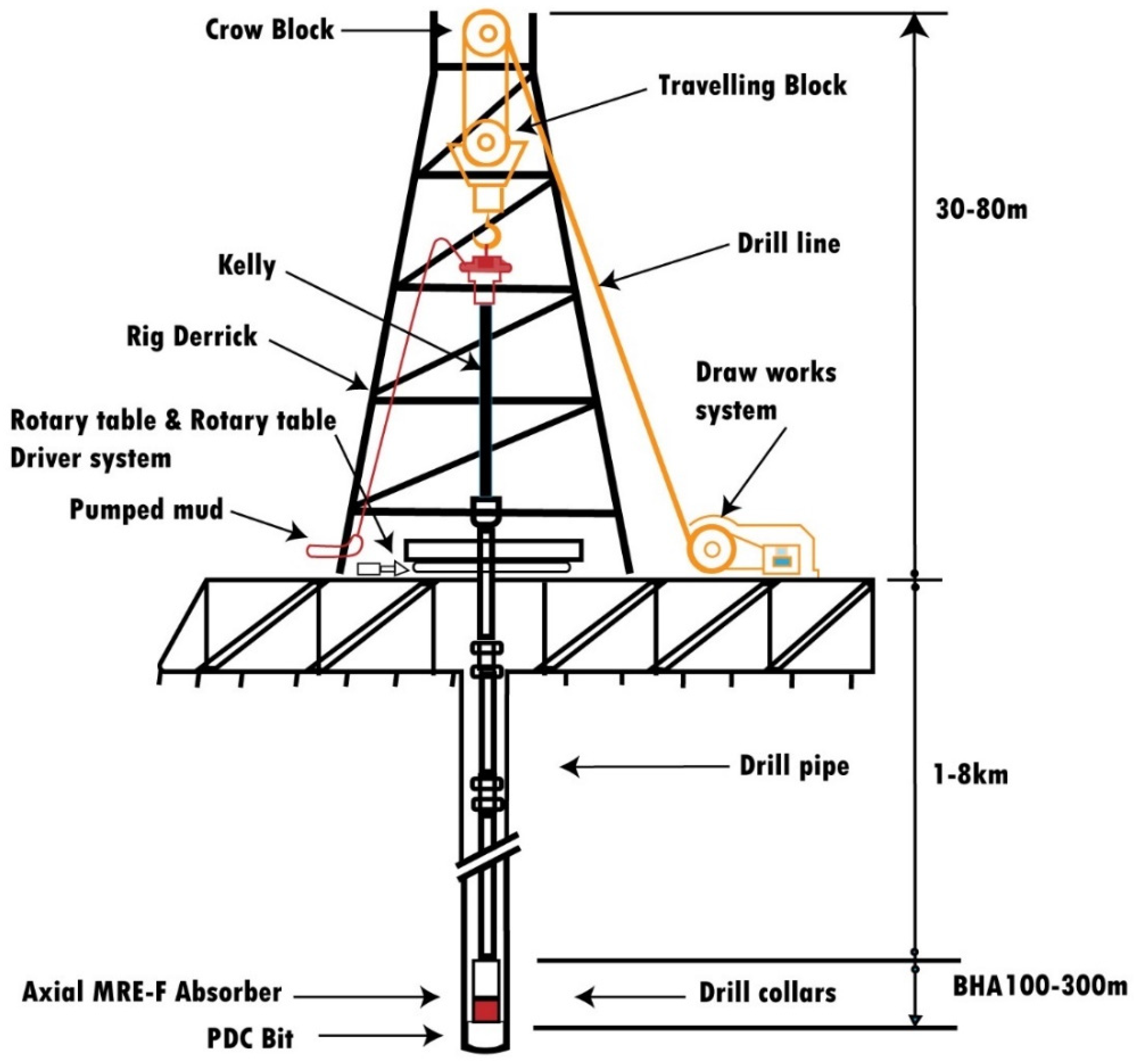
A vertical rotary drilling system comprises several key components: the derrick, and the hoisting setup, which includes the drill lines, suspension mass (swivel, kelly, and traveling block), and drawworks system. Two drive systems are considered in the model that control both vertical and torsional motions (refer to Figure 2). The drill strings consist of the bottom-hole assembly (BHA), Lb in length, primarily comprising thick-walled heavy steel tubes that apply axial force on the formation; it also includes drill pipes, Lp in length, made from thinner-walled steel tubes connected to the suspension mass via the kelly. To maintain stability and to control the drilling process, the entire drilling system is held via the drill lines, with vertical movement regulated by the drawworks’ drive motor. The torque needed to drive the drill bit is produced by a rotary table motor at the surface. The rotary table stores the kinetic energy to sustain the required rotational speed. Energy produced at the surface of the rig is transferred to the drill bit through the drill pipes. The present study employs a lumped-parameter model to represent the drill string’s vertical and torsional movements; the system inertia and stiffness characteristics are represented by equivalent parameters.
The model’s equivalent parameters in the axial and torsional directions of motion, such as equivalent mass, inertia, and stiffness, were mainly derived from the corresponding continuous model by following a Lagrangian method [47], as shown in Table 2. The use of a discrete model to represent the continuous system arises from the need for a reasonably precise yet manageable depiction of the system’s complex behavior. The lumped-parameter approach, widely adopted by many researchers, has proven effective for qualitative dynamic analysis [21,22,23,27,29,48,49]. While including higher modes would influence dynamics, the lower modes are the most significant in the response, particularly for vertical wells without bending vibrations. Field measurements also provide substantial evidence that stick–slip vibrations at the drill bit are primarily influenced and dominated by the first fundamental torsional vibration mode of the drill string [4,8]. The equations of motion developed in this study include the main torsional and axial components of the vertical rotary drilling system, a realistic bit–rock interaction model, and significant incorporation of a semi-active axial MRE-F absorber device installed above the bit. This study investigates the new dynamics when incorporating the axial MRE-F absorber into the drilling system and explores its influence on stabilizing the drill bit axially during cutting and reducing the axial vibrations excited by various sources, such as the drill string’s flexibility, the hoisting system’s dynamics, and especially bit–rock interactions. The goal is to reduce the occurrence of torsional stick–slip and axial bit-bounce during drilling under critical operational conditions, achieving smooth drilling. Table 2 include the symbols and parameters values utilized in this study.

2.1. Axial and Torsional Equations of Motion

The hoisting mechanism initially holds the drill string in suspension. Using the drawworks’ drum, the drill line is extended, causing the drill string to lower gradually until the bit contacts the bottom-hole formation. At this stage, a fraction of the weight of the bottom-hole assembly (BHA), known as the applied weight on bit (WOBo), acts as an axial force exerted on the drill bit and then into the formation, enabling the cutter to move forward. Consequently, the hoisting mechanism controls the force applied (WOBo) to the bottom rock and the top axial speed of the drill string during drilling. Figure 3a illustrates the simplified axial model. The length from the crown block to the traveling block is represented by L. In the beginning, L is equal to the initial length (denoted as Lo), and its length increases via the drawworks’ drum until it equals the drill pipe length for each run, with the drill pipes stored in the stand. It is assumed that the drawworks’ drum is powered by a DC motor with armature control via the associated gearbox. The equations of motion, which describe the axial behavior of the drilling system—including the hosting system, suspension mass (top mass), BHA, and drill bit, along with the proposed axial MRE-F absorber—can be formulated as follows:
L c I ˙ + R m I + K m n D W θ ˙ D W = V c
J D W + n D W 2 J m s θ ¨ D W + T f r = T L + T D W
m T o p x ¨ T o p + C d s x ˙ T o p x ˙ a + k d s x T o p x a = m T o p g F h o o k
m a x ¨ a + C d s x ˙ a x ˙ T o p + k d s x a x T o p + C m r x ˙ a x ˙ b i t + K m r x a x b i t = m a g
m b i t x ¨ b i t + C m r x ˙ b i t x ˙ a + k m r x b i t x a = m b i t g W O B
m a = m B H A + m f + 1 3 m p i p e
The first two equations represent the behavior of the drawworks’ drum and drive DC motor torsionally, which control the top mass motion. The dynamics of the drawworks’ drive DC motor are governed by Equation (1). The term θ ˙ D W refers to the torsional velocity of the drawworks drum. The motor constant is denoted by Km, and the motor armature current is represented by I. The input voltage VC, which drives the DC motor, is determined based on the desired drum velocity W d d (refer to Table 2), the armature resistance Rm, the gear ratio n D W , and the inductance Lc. Equation (2), which describes the drawworks’ behavior, can be derived by applying Newton’s second law to the drum, where θ ¨ D W refers to the torsional acceleration of the drum, while J D W and J m s represent the inertia of the drum and motor shaft, respectively. The torques acting on the drawworks drum, as shown in Figure 3a, include the drill-line torque TL, caused by the drill string’s partially suspended weight, the friction torque Tfr used to control the drum’s movement, and the motor torque TDW. The equations for these torques are provided in Table 2. Equations (3), (4) and (5) represent the axial dynamics of the suspension mass, the equivalent lumped mass of the bottom-hole assembly (BHA) and drill pipes, and the drill bit, respectively. In a similar manner, these equations are derived by summing the forces acting on each component along the axial direction, as depicted in the simplified model in Figure 3a. The suspension mass axial response is denoted as x T o p , while the axial responses of the bottom-hole assembly (BHA) and the drill bit are denoted by x a and x b i t , respectively. The parameters m a , m T o p ,   m b i t , k d s , C d s ,   g , and weight on bit (WOB) are defined as follows: m a is the effective mass, as outlined in Equation (6); m T o p is the suspension mass; m b i t is the bit mass; k d s is the axial drill string’s stiffness; C d s is the axial drill-string damping; g is the acceleration due to gravity; and WOB is the downhole weight force on the bit. The linear MRE-F axial absorber is installed between the bit and the BHA, functioning as a coupling between both components. On the other side, the applied weight on bit (WOBo) force, considered to represent the required WOB, acts as an internal interaction instead of a set axial value; it is determined at the top by subtracting the hook load (Fhook) from the total weight. Notably, the inclusion of the entire axial drive system’s dynamics in the current model allows for a better capture of axial vibrations, thereby offering a realistic evaluation of the assumed axial MRE-F absorber’s effectiveness in the drilling system.
Although the MRE-F absorber typically behaves nonlinearly, often leading to complex nonlinear differential equations that complicate analysis, in this study, the absorber operates under small displacement deformations, as will be shown in the results. Given these small deformations, a linear system model was adopted [51] to simplify the modeling process [36,52]. This choice not only avoids the complexity of nonlinear modeling but also ensures that the analysis remains manageable and accurate. Therefore, the simplified MRE-F absorber model strikes a practical balance between accuracy and ease of analysis [53].
The simplified torsional model is shown in Figure 3b, and the equations of the drill string’s torsional motion and the rotary table components, along with the drive motor, are as follows:
L i I ˙ m + R m o I m + K m o n o θ ˙ r t = V C D
J r t + n o 2 J m θ ¨ r t + K θ r t θ + C r t θ ˙ r t n o T m o = 0
J θ ¨ + C V θ ˙ + K θ θ r t = T O B
T m o = K m o I m
J = J B H A + 1 3 J p i p e
The dynamics of the motor and the rotary table are described by the first two equations, where θ and θ r t are the bit and the rotary table angular responses, respectively, I m denotes the motor armature current, K m o is the motor constant, n o is the gear ratio of the gearbox, R m o and L i represent the motor armature resistance and inductance, respectively. The supply voltage to the motor is given by V C D . With the purpose of achieving the desired rotational speed (wd) for the rotary table, the necessary motor voltage is determined as shown in Table 2. The torque at the motor shaft, which drives the rotary table, is denoted by T m o . The third equation represents the BHA along with the bit’s torsional behavior, which is assumed to be rigidly connected.
The lumped model’s equivalent parameters of the drill string are derived using a Lagrangian approach, assuming a one-mode approximation for the torsional and axial deformations of both the BHA and the drill pipe. The lateral oscillations are not accounted for, and the drill collars are reasonably rigid with respect to the drill pipes, which are modeled as long elastic rods. Furthermore, the rotary table, derrick, drill bit, and suspension mass are treated as rigid bodies. The distributed mass and inertia of the drill pipes are lumped into the bottom-hole assembly along with an effective stiffness in both the axial and rotational directions. Furthermore, the drill lines are modeled as a simple spring as shown in Table 2.

2.2. Bit–Rock Interactions

The PDC bit–rock interaction model [30] describes the cutting reactions by dividing the cutting forces into two distinct components: cutting forces and frictional forces. The cutting forces stem from the blade’s interaction with the rock. Bit–rock interaction law, which represents vertical drilling of the PDC bit with its speed aligned to its rotational axis and spinning around its symmetrical axis (i.e., lateral movement is not considered), is derived by summing the effects of a single cutter across the drill-bit configuration. The total weight on bit (WOB) and the torque on bit (TOB) are calculated by integrating the cutting force on the blade’s cutting edges and the frictional force at all contact points between the wear-flat and the rock. The experiments demonstrated that PDC bit behavior can be divided into three distinct operational phases [54,55]: Phase I, Phase II, and Phase III. These phases correspond to how the contact forces change with the instantaneous cut depth. The drilling process initiates with Phase I, which is dominated by frictional contact processes. During this phase, the contact forces increase with the depth of cut (d), the depth of cut remains shallow, and the contact forces’ frictional component is below the threshold value WOBf. The cutting failure mode at shallow cut depths is a ductile mode [56], involving the shearing of the rock ahead of the cutter edge and crushing the particles beneath the cutter. Consequently, Phase I assumes that the bit induces elastic deformation in the formation. In this phase, the WOB can be modeled using a quasi-static approach along with the linear stiffness coefficient kc, which is calculated based on the formation’s yield strength and elastic properties [29]. Phase II takes place when the drill bit advances further into formation and reaches or surpasses the critical depth of cut ( d * ), where the contact forces become fully engaged and remain constant even with further increases in the depth of the cut. This indicates that the vertical contact stresses have attained their maximum level σ, preventing further penetration. The length of contact at this stage has reached the limit, indicating a bit bluntness. In Phase II, WOBf = WOBf*. Thus, any further increase in the WOB will lead to an increase in the WOBc. The last phase is Phase III; during this phase, the contact surface area increases, and the frictional component of the WOB surpasses its threshold (WOBf > WOBf*). The bit’s response becomes non-unique due to various factors, including cutter distribution, bit design, mud characteristics, mud flow rate, and rock attributes. Phase III is not addressed in the present study, and it is assumed that the hole fragments are effectively cleaned during the cutting process. The model of bit–rock interaction, encompassing Phases I and II and their corresponding boundary conditions at the drill bit, is adopted from Kamel and Yigit’s 2014 study [21], outlined as follows:
Weight on bit and torque on bit friction components:
W O B f = 0   i f   d 0   O f f   C o n t a c t   k c d   i f   d < d *   p h a s e   I R b σ l f x ˙ a   i f   d d *   p h a s e   I I T O B f = γ W O B f R b 2 μ f θ ˙
f x ˙ a = 1 1 + e 20 4 x ˙ a 1.5 f ( θ ˙ ) = tanh ( 70 3 θ ˙ + 2 )
Weight on bit and torque on bit cutting components:
W O B c = 0   i f   d 0 ζ ε R b d   i f   d > 0 T O B c = 0   i f   d 0 ε R 2 b 2 d   i f   d > 0
Instantaneous combined depth of cut (d) and equivalent wear-flat length ( l ):
d = n d n = n x a t x a t t n l = n l n
When d < 0 , it signifies that the drill bit has lost contact with the formation, leading to a phenomenon known as bit-bounce, and all forces are diminished to zero; f x ˙ a   a n d   f ( θ ˙ ) are Heaviside functions that are used to capture the bit boundary conditions, specifically the axial unloading path of the bit in Phase II and the sign of the TOBf when the bit rotates in reverse (although this was not observed in present study), thereby avoiding singularity. The model assumes an ideal PDC bit with n blades identically spaced at an angle of 2 π n . Each blade in the drill bit is treated as a vertical cutting surface, with fixed length l n of the wear-flat chamfer perpendicular to the cutting face. The rock thickness ahead of the cutting edge, which is represented by the depth of cut per blade (dn), remains uniform along the blade, with all blades being exactly similar. Consequently, dn is associated with the current axial response x a t and pervious response x a t t n at the delayed time tn, which is the time interval needed for the drill bit to complete a rotation by an angle of 2 π n to achieve its present angular position [57].
The equations of motion used in this study are nonlinear where the nonlinearity arises from several sources: (i) the bit/rock interaction forces, which include nonlinear cutting and friction terms governed by phase-dependent behavior; (ii) the use of time-delay elements that model the regenerative effect of cutting depth; and (iii) the coupling between axial and torsional dynamics, where both weight on bit and torque on bit depend on the bit’s axial and angular motions. Additionally, the use of Heaviside functions to capture transitions between different cutting regimes introduces further nonlinearity into the system. These characteristics enable the model to accurately capture complex dynamic behaviors such as stick–slip and bit-bounce, which are commonly observed in drilling operations.

3. Results and Discussion

The drill string’s dynamic behavior is determined numerically by solving equations of motion under given proper initial conditions. This is performed by integrating the equations of motion using a Runge–Kutta solver in MATLAB platform (R2019a). The drawworks system suspends the entire drill string via the drill lines and controls the drill string’s movement axially by adjusting the suspension mass’s position from the top. This allows a fraction of the bottom-hole assembly (BHA)’s weight to be transferred to the bottom-hole formation as the applied weight on bit (WOBo), thereby initiating and sustaining the cutting process. Torsionally, the applied torque that must be transmitted via drill pipes to drive the bit is mainly produced by rotary table’s drive motor. In this simulation, the axial and angular velocities of the drilling system were set under critical conditions to assess the performance of the assumed axial MRE-F absorber. In this way, this study focuses on understanding how different absorber coefficients affect the stabilization of the drill bit along the axial direction. All parameters used in this study are listed in Table 1 and Table 2.
Initially, the entire drill string is suspended using the drill line via the drawworks system, with the axial initial conditions specified as follows:
x T o p 0 = m b i t + m a + m T o p g K s x a 0 = x T o p 0 + m a g K d s x b i t 0 = x T o p 0 + x a 0 + m b i t g K m r
Next, the system is gradually lowered from the top using the drill line, which is extended by the drawworks until the PDC bit contacts the bottom formation, the cutting process starts, and the suspension mass attains the required top axial velocity Vd. The increase in axial velocity is managed by the drawworks’ motor and is mathematically expressed by a hyperbolic tangent function in the supplied voltage, VC.
V c t = K m n D W N V d R D W tanh ( b o t )
The drilling strategy explored in this study involves gradually lowering the drill string from the top and sustaining drilling to achieve a specific applied weight on bit (WOBo). This weight depends on the desired velocity of the top suspension mass, top torsional applied speed, and a fraction of the bottom-hole assembly’s weight that is released to be applied to the formation. Initially, the bit is rotated off-bottom at the desired torsional velocity and lowered gradually until it touches the formation, starting the cutting process. The proposed model is designed to capture the drilling system’s reactions that commence when the PDC bit contacts the formation from its off-bottom position, creates an initial indentation, and then starts cutting the bottom rock.
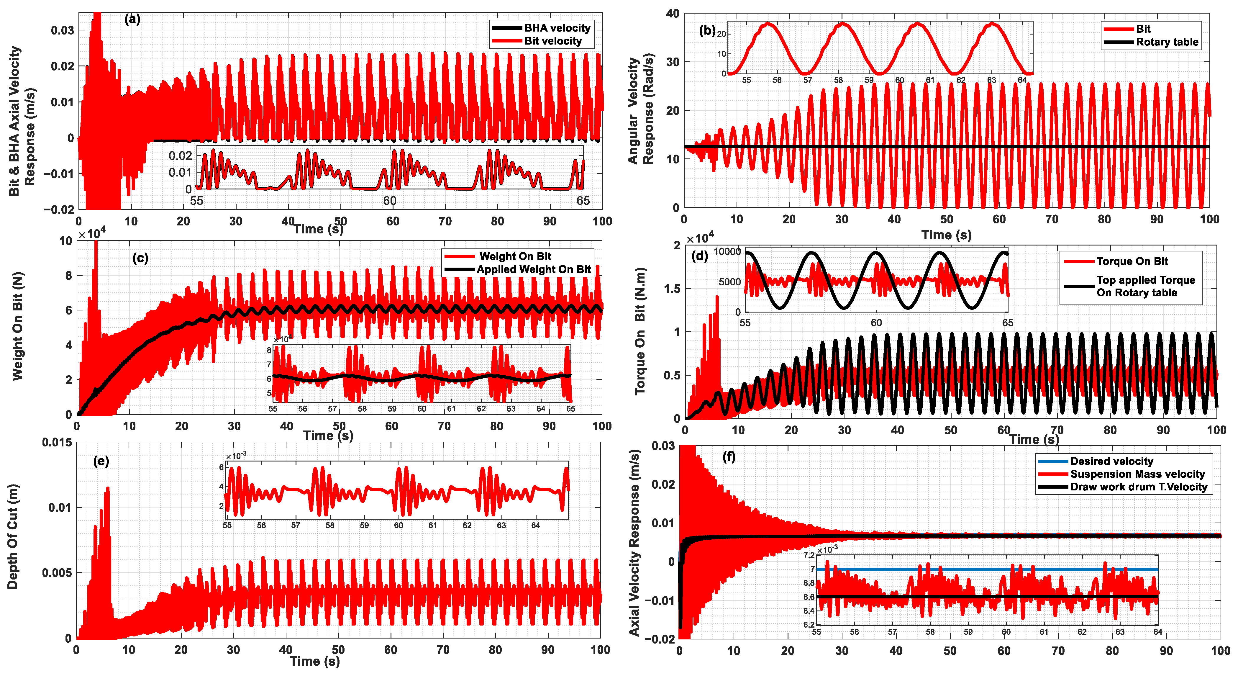
Figure 4a–f illustrates the responses of the drilling system equipped with a proposed semi-active control device (axial MRE-F absorber) at initial values. The operational parameters for this simulation were set based on severe vibration drilling conditions. Therefore, the top axial feed speed was set to 7 mm/s, while the rotary table’s torsional speed was adjusted to 120 rpm. The suspension mass speed was gradually increased from zero to the desired speed (Vd) using the drawworks’ motor, resulting in an increase in the applied weight on bit (WOBo). Consequently, the drilling system exhibited violent vibrations characterized by torsional and axial stick–slip, with the drag bit oscillating torsionally at twice the top applied speed (Vd), as depicted in Figure 4a,b. This behavior is consistent with the analytical predictions and field observations (refer to [2,21,58,59]). It was observed that, at steady state, the torsional vibration amplitudes remain constant, indicating that the stick–slip vibrations complete a full cycle. Notably, throughout the stick–slip vibrations, the high inertia of the rotary table, also known as the flywheel effect, effectively controls the rotary table’s velocity, as shown in Figure 4b.
Figure 4a,b illustrates that the drilling system experienced severe vibrations in both the axial and torsional directions, displaying complete stick–slip cycles. These cycles began with a decrease in the bit velocity to zero (sticking) and then continued with the bit’s release, reaching very high velocities in both directions. During the same period, Figure 4c–e shows that as the angular and axial velocities of the drag bit began to decrease, the torque on bit (TOB) and weight on bit (WOB) also decreased. Consequently, the depth of cut (d) began to show reduced fluctuations. Subsequently, the bit started to stick torsionally and axially, and the relative depth of the cut stabilized. This means that the cutting component forces remain steady during this period, while the friction components change during sticking because the friction component of the weight on bit (WOBf) relies on the axial velocity response of the drag bit. Figure 4a shows a zoomed section depicting the bit’s axial velocity fluctuation during the stick–slip, reflecting a gradual indentation change in the formation. This explains why the weight on bit’s friction component (WOBf) decreases below the threshold value as the drill bit’s velocity reduces to zero while sticking axially and then increases before dropping to zero once more. Additionally, it demonstrates that the axial velocities of both the bit and the bottom-hole assembly (BHA) are identical, indicating a rigid connection. This rigidity can be attributed to the high initial values of the assumed stiffness and damping coefficients of the proposed axial MRE-F absorber.
Figure 4c illustrates the gradual increase in the applied weight on bit (WOBo) from zero up to a steady-state value, with the weight on bit (WOB) fluctuating around it. Phase I of the bit–rock interaction begins, marked by a short duration (less than 20 s) and a relatively low WOBo, causing light oscillations in the bit’s angular velocity, as depicted in Figure 4b. Phase I, defined by a shallow cut, results in a low rate of penetration (ROP), as illustrated in Figure 4a. As a greater percentage of the weight from the bottom-hole assembly (BHA) is transferred to the formation, the WOB increases, pushing the depth of the cut to surpass the critical limit d*, transitioning the bit–rock interaction into Phase II, as illustrated in Figure 4e. In this phase, the weight on bit’s friction component (WOBf) reaches its threshold (WOBf*), which remains constant irrespective of the depth of cut. This indicates that the normal contact forces do not increase any further, as the axial contact stress has reached the rock’s maximum normal contact stress (σ). Consequently, the actual contact length between the cutter’s wear-flats and formation reaches its limit, and no more indentation occurs, indicating bit bluntness. Therefore, any further increase in WOB translates into the cutting forces. As Phase I transitions to Phase II, the bit-bounce ceases, and stick–slip vibrations start to emerge, as shown in Figure 4a,b. This transition results in simultaneous increases in the WOBo, WOB, TOB, and the top applied torque, as illustrated in Figure 4c,d, due to the coupling in both axial and torsional oscillations.
Figure 4c demonstrates that the weight on bit (WOB) and applied weight on bit (WOBo) both gradually and simultaneously increase, causing an increase in the WOB’s cutting and friction components. This gradual increase leads to significant oscillations in the depth of cut, TOB, and WOB because of stick–slip vibrations at the bit, as illustrated in Figure 4b–e. The WOBo also shows oscillations because of the nature of the coupling dynamics, and in this model it is considered to be a calculated variable rather than a predetermined fixed value, as highlighted in the zoomed portion of Figure 4c. Essentially, the fraction of the BHA’s weight applied to the bottom formation increases gradually as the bit velocity decreases, until it sticks, and then decreases when the suspension mass velocity slows down as the bit velocity increases. Additionally, in the same manner, Figure 4d indicates that the torque applied on the rotary table at the surface increases as the bit’s torsional velocity reduces to a stick, reflecting the stored rotational energy in the drill pipes, which releases when slippage occurs. This results in large TOB amplitudes because of the stick–slip at the bit. It is remarkable to note that one significant sign of axial bit vibration is the wavy profile of the formation. Figure 4e illustrates fluctuations in the depth of the cut, indicating a sinusoidal formation profile resulting from these axial vibrations. This profile is the main excitation source of axial vibration, showing a mutual effect between the bit’s axial movement and the formation profile [60]. The primary aim of this work is to mitigate violent axial and torsional vibrations by stabilizing the bit axially during cutting and preventing axial impact waves from being transmitted to the BHA from bit–rock interactions, and vice versa. This can be achieved through the integration of the proposed axial MRE-F absorber into the drilling system.
Figure 4f illustrates that the oscillation of the suspension mass’s velocity response away the desired velocity of the drill line is due to the dynamics of the drill line and drawworks. The suspension mass vibrations are clearly caused by the force coming from the BHA, which results from bit–rock interaction [50]. From Figure 4a,f, it is apparent that both the suspension mass and the BHA exhibit strong axial oscillations during the initial 10 s, primarily owing to the initial stage of indentation and subsequent collisions with the formation, known as bit-bounce. Following this period, the bit sets on the bottom formation, and a portion of the BHA’s weight is used as applied weight on bit (WOBo). The model of the lumped mass assumes that the entire BHA undergoes bouncing. However, the bit-bounce phenomenon only impacts the lower section, which leads to an overestimation of the impact severity and the resulting vibrations. Consequently, the tested assumed tunable axial MRE-F absorber in this model provides a conservative approach for mitigating severe vibrations.
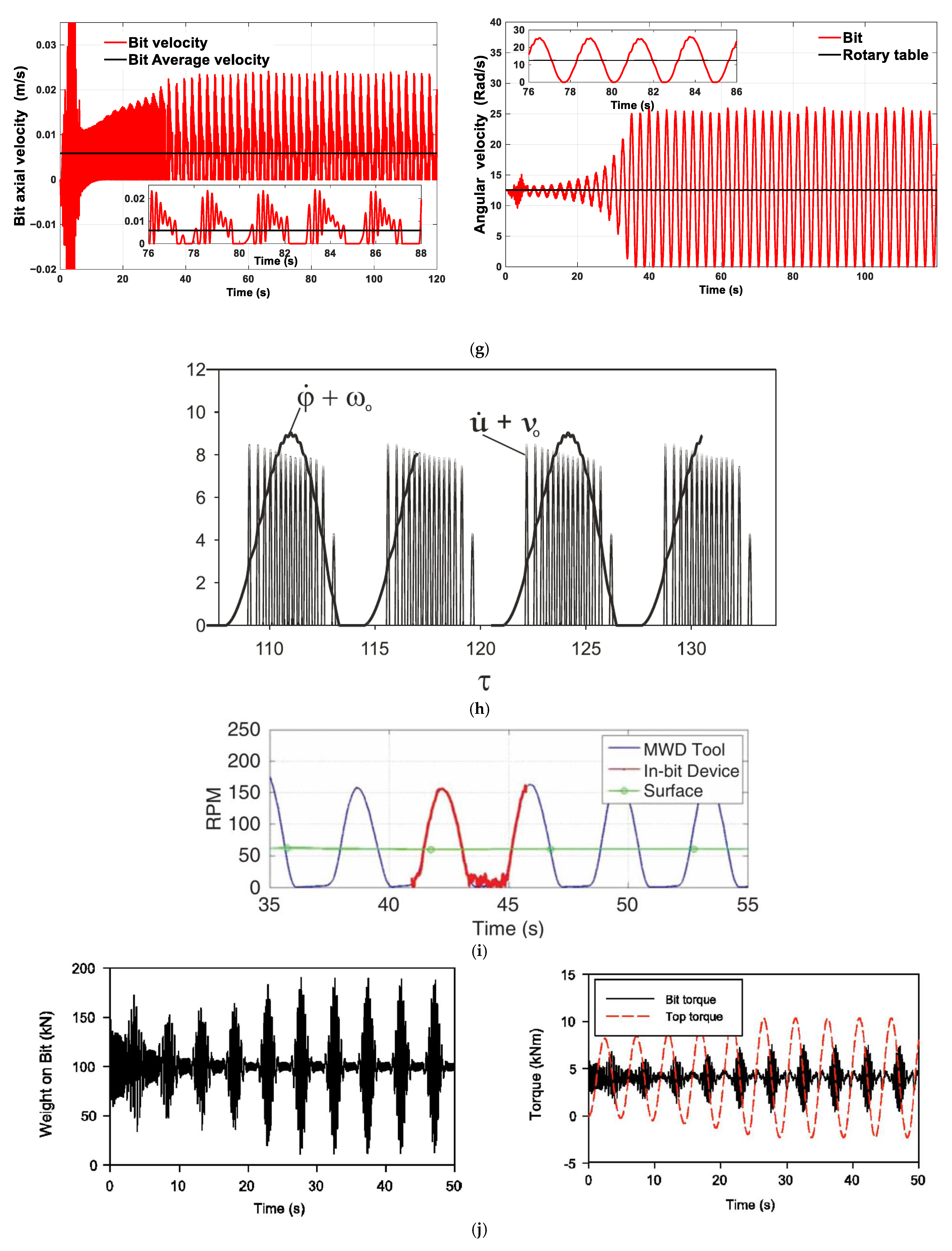
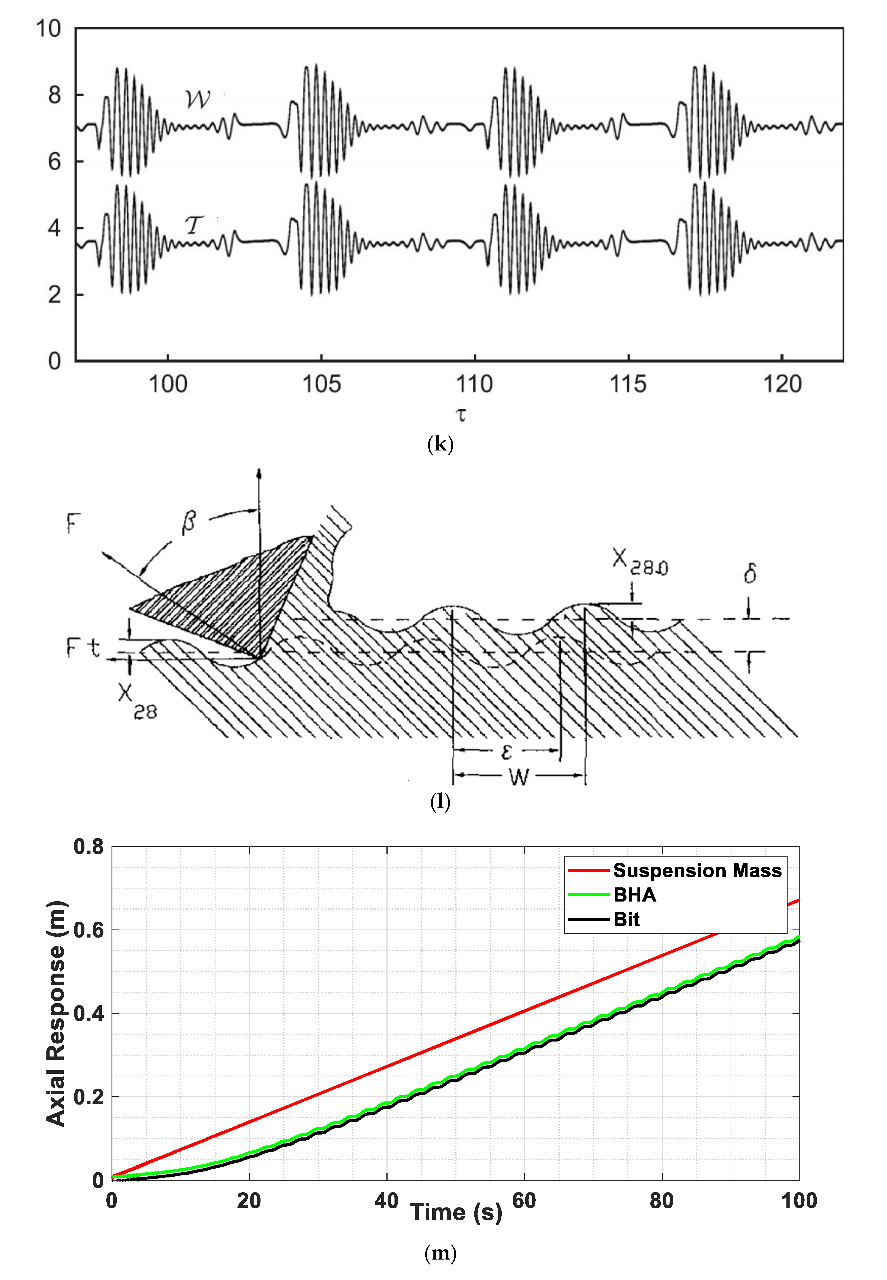
Figure 4. System response at initial MRE-F absorber coefficients (Kmr 100% and Cmr 100%), wd = 120 RPM, and Vd = 7 mm/s: (a) Bit and BHA axial velocity response; (b) Rotary table and torsional velocities; (c) Weight on bit and applied weight on bit; (d) Top applied torque on rotary table and torque on bit; (e) Depth of cut; (f) Top axial desired velocity, suspension mass axial velocity, and drawworks drum tangential velocity; (g) Simulation results published by Kamel and Yigit, 2014 [21]. Figure shows the axial (left side) and torsional (right side) velocities responses at stick slip (V_d = 7 mm/s and W_d = 120 RPM). (h) Simulation results published by Germay et al. (2009) [58], Figure shows the dimensionless axial and torsional velocities responses at stick slip. (i) Downhole measurements published by Ledgerwood et al. (2013) [3]. Figure shows the bit torsional velocity response recorded at stick slip. (j) Simulation results published by Yigit and Christoforou (2006) [29]. Figure shows the weight on bit (left side) and torque on bit (right side) at stick slip. (k) Simulation results published by Richard et al. (2007) [57]. Figure shows the dimensionless weight on bit and torque on bit at stick slip. (l) Formation profile due to Axial vibration published by Elsayed et al. (1997) [61]. (m) Axial displacement responses of the suspension mass, BHA, and bit under initial absorber coefficients values, demonstrating minor, stable deflection across the MRE-F absorber, supporting the linear model assumption.
Actuators 14 00273 g004aActuators 14 00273 g004bActuators 14 00273 g004c
Following the previously discussed results, the model was further validated by simulating a system configuration with high MRE-F stiffness and damping coefficients, effectively representing an MRE-F absorber as a rigid connection between the drill collar and the PDC bit. This configuration serves as a key validation case, allowing for direct comparison with published analytical results and recorded field data. Figure 4a,b depicts the bit’s axial and torsional oscillation velocities under critical operating conditions, with both velocities exceeding twice their desired values—axially ( V d ) and torsionally ( W d ). These oscillations capture the stick–slip phenomena effectively, aligning closely with the predictions of Kamel and Yigit (2014) [21]. Additionally, the model qualitatively matches the results published by Germay et al. (2009) [58], as shown in Figure 4g,h, and field data from Ledgerwood et al. (2013) [3], as shown in Figure 4i, further supporting the validity of the proposed model.
Figure 4c,d highlights the variations in the weight on bit ( W O B ) and torque on bit ( T O B ), along with the dynamic fluctuations of the applied W O B and surface-applied torque. These variations emerge due to the coupling dynamics between the system and the bit-rock interactions, which act as self-exciting vibration sources. The results are consistent with the published works of Yigit and Christoforou (2006) [29], as shown in Figure 4j, and Richard et al. (2007) [57], as shown in Figure 4k, further confirming the accuracy of the model in capturing these dynamic interactions.
Additionally, Figure 4e illustrates the depth of cut, which reflects the wavy profile of the formation caused by axial bit vibrations. This figure highlights the role of axial vibrations in creating such a profile, consistent with findings from Elsayed et al. (1997) [61], as shown in Figure 4l. The depth of cut fluctuations indicate that the bit-rock interaction plays a significant role in exciting axial vibrations.
Figure 4f shows the suspension mass vibrations resulting from B H A dynamics and drill line interactions. These vibrations align with Aarrestad and Kyilingstad’s (1993) [50] conclusion, who noted similar dynamic effects. The model’s capacity to simulate these effects further validates its ability to accurately represent the complex behavior of the drilling system.
Finally, to further support the MRE-F modeling assumptions discussed earlier, Figure 4m presents the axial displacement responses of the suspension mass, bottom-hole assembly (BHA), and bit at the initial absorber’s coefficients values. This figure clearly shows that the axial responses of the BHA and bit are closely aligned, with only a minor, stable deflection between them during the entire drilling operation.
This observation confirms that the MRE-F absorber undergoes small axial deformations under the studied conditions. As a result, the use of a linearized absorber model, as described in the mathematical modeling section, is validated. The small and consistent deformation ensures that the nonlinearity inherent to MRE-F materials has negligible influence on the operating parameters’ system dynamics. Therefore, the linear modeling approach provides a sufficiently accurate representation of the absorber behavior, while preserving analytical tractability and modeling efficiency.
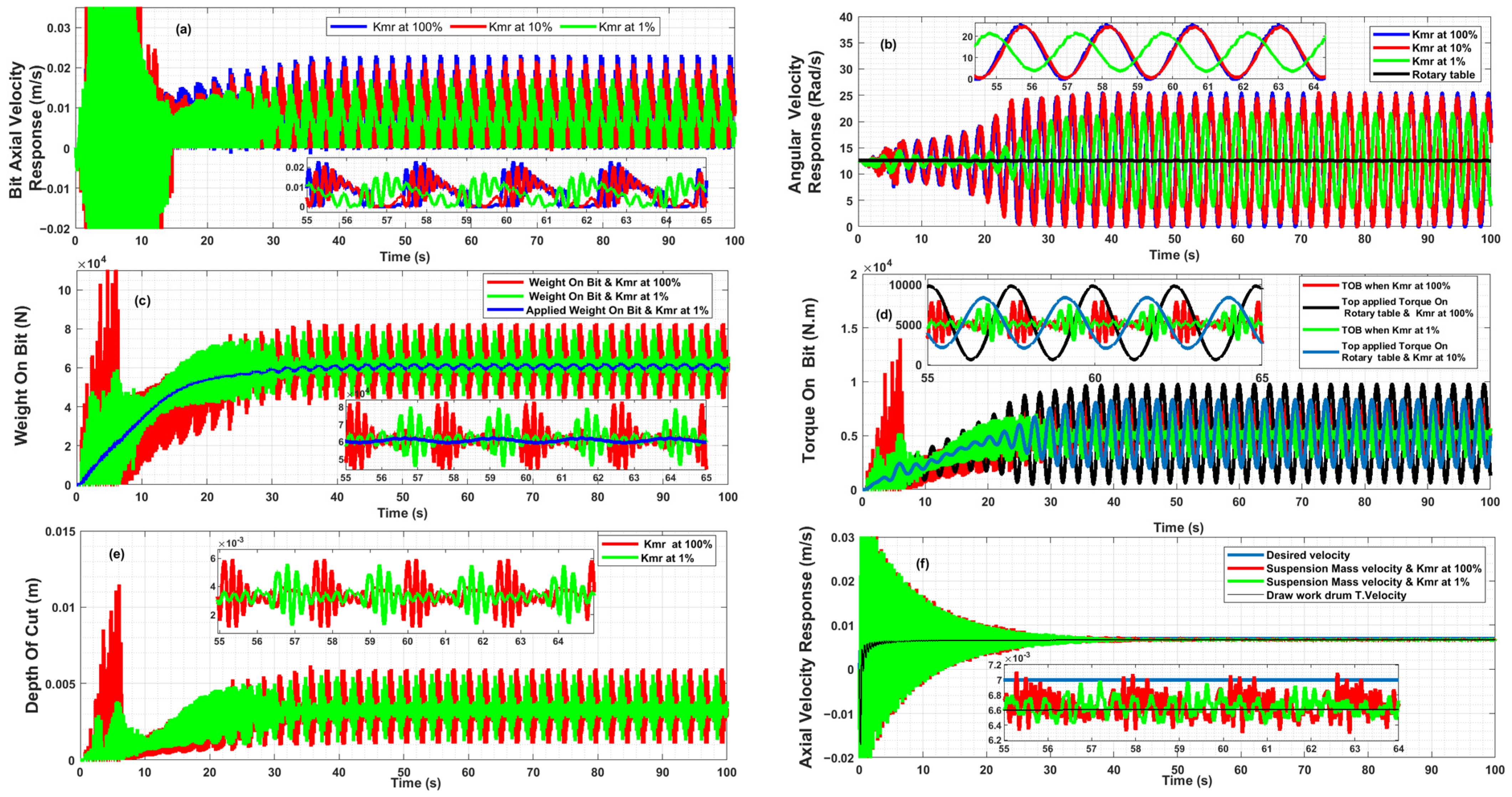
Figure 5a–f shows the responses of the drilling system at different values of the axial MRE-F absorber’s stiffness coefficient and fixed damping coefficient (100% of its initial value), in order to investigate their effects on the drill string’s behavior under the same critical operational parameters. In the same manner, the top release speed is increased gradually from zero up to the desired speed (Vd) via the drawworks’ motor, and a fraction of the BHA’s weight is applied to the bottom-hole formation and increased until the desired weight on the bit is attained. Simultaneously, the bit–rock interaction begins with Phase I and then progresses to Phase II. Figure 5a,b shows the axial and torsional bit velocities’ responses, respectively, where the amplitudes of both velocities are reduced and slightly shifted. It is remarkable to observe that the reduced and slightly shifted responses became apparent when the stiffness coefficient fell to 1% of its initial value, where due to the high initial coefficient value, the axial MRE-F absorber behaved as rigid rather than as a flexible connector between the bit and the BHA; hence, this could be explained as part of the energy generated at the bit–rock interaction during the cutting process, which travels from the bit to the BHA and reflects back to the bit, where it is dissipated by the axial MRE-F absorber. The absorption becomes more pronounced at the lowest stiffness value, as shown in Figure 5, resulting in a reduction in unwanted vibration amplitude and slightly improving the bit response during cutting, which further proves that the main source of self-excitation comes from the waves generated by the bit–rock interaction. Controlling the bit axially has a significant impact on the drilling process, in a more effective manner than focusing on torsional control, as confirmed by other researchers using different methods, such as the development of the fixed and self-adjusted depth of cut control unit proposed by Schwefe et al. [62], which limits the WOB and is self-adjustable for a variety of drilled rock types, so as to ensure that the depth of cut does not surpass the threshold value when drilling different formations. However, with this method, the optimal depth of cut needs to be predetermined for each formation type and fed accurately into the control unit, which is not practical in real-world scenarios, where lithology is a variable and uncontrollable parameter. In contrast, the proposed method is applicable to different formations by self-adjusting the coefficients as assumed over a wide range of stiffness and damping values, allowing it to absorb excess energy and transmit the optimal WOB into the formation by stabilizing the bit axially. The impact on the WOB and TOB is illustrated in Figure 5b,c, where their fluctuation amplitudes are clearly reduced due to the depth of the cut being slightly reduced (as shown in Figure 5e), which, in turn, reduces the WOB and TOB’s cutting and friction components, consequently reducing the applied TOB and the initial impact. The zoomed portion of Figure 5f shows the interesting observation that the axial vibrations of the suspension mass are clearly reduced as a result of the reduction in axial vibration waves transmitted to the drilling system from the bit.
Figure 6a,b shows that continued reduction in the axial MRE-F absorber’s stiffness coefficient value will adversely impact the drill-string behavior under the same operational parameters. The bit vibrates violently in axial direction while the BHA moves almost smoothly due to the high flexibility of the absorber, which, in turn, reduces the axial applied force to the bit (WOBo); hence, the depth of cut (d) and the bit’s indentation into the formation, WOB and TOB cutting, and friction components will be reduced while the bit rotates freely.
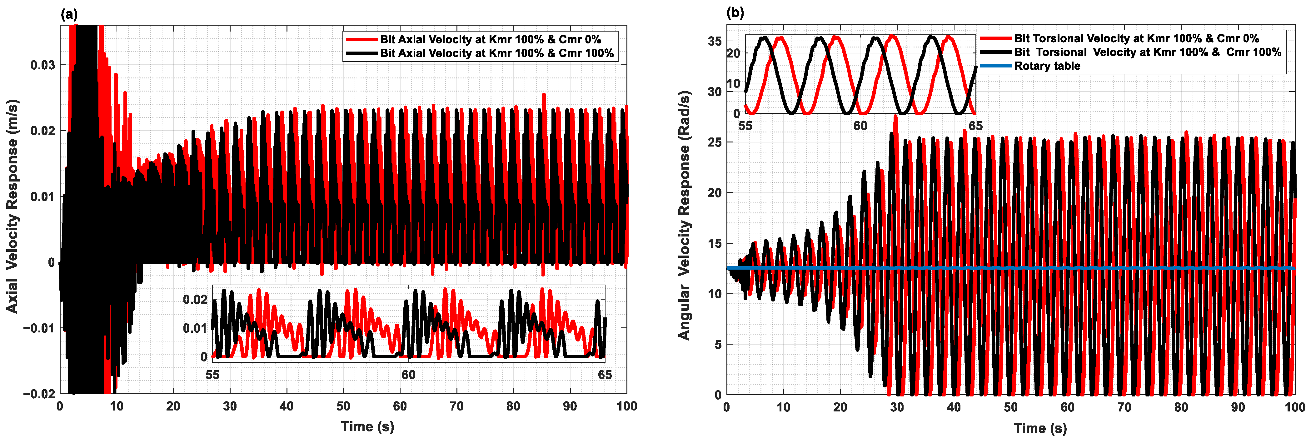
Figure 7d shows the responses of the drilling system to variations in the axial MRE-F absorber’s damping and stiffness coefficients at both initial and lower values under the same critical top operational parameters (i.e., top axial feed and rotary table torsional velocities). In the same manner as the top release speed is gradually increased from zero to the desired speed (Vd), the applied weight on bit (WOBo) is increased until the desired weight on bit is attained. Simultaneously, the bit–rock interaction progresses to Phase II. Figure 7a,b shows that the observed damping effects result in a shifted response with almost negligible effects on the amplitudes, and due to their high stiffness, the bit and BHA can be considered to be rigidly connected. However, Figure 7c,d illustrates the significant impact of damping when the stiffness coefficient is low. At these lower stiffness values, both the axial and torsional response amplitudes increase dramatically. This is due to the low resistance and high flexibility of the absorber, which prevents the optimal axial force from being transmitted to the bit, resulting in failure to absorb the excess energy generated during the cutting process.

4. Axial Absorber Coefficients’ Optimal Values

Based on the preceding discussion, it is evident that the rotary drilling system was simulated under critical surface operational parameters, where violent vibrations existed simultaneously in the axial and torsional directions, manifesting as bit-bounce and stick–slip, respectively. The effects of adding an axial MRE-F absorber to the drilling system were investigated over different absorber coefficient values. It was found that the drill string’s behavior is significantly affected by the absorber’s damping and stiffness coefficient values; therefore, it is highly desirable to optimize the selection of these coefficient values in order to achieve smooth and efficient drilling. Minimizing the torsional and axial vibrations at the bit results in smooth drilling. In an ideal scenario, the torsional and axial speeds should align closely with their desired velocities (i.e., the axial top velocity (Vd) and the surface rotary table speed (wd)). An objective function can be established using the root mean square (RMS) value to obtain the smoothness index, which is a weighted function calculated from the percentage variation in both velocities (Equation (18)) [21].
S m o o t h n e s s I n d e x = 1 T 0 T α 1 1 θ ˙ w d 2 + 1 α 1 1 x ˙ a V d 2 d t 1 / 2
where T is the total drilling time, α 1 is the weight factor ( 0 α 1 1 ) used in the function for both bit velocities’ responses. In the event that both responses are equally important, they should each be assigned a weight of 0.5. As the bit’s axial and torsional velocities near their target values, the smoothness index approaches zero, indicating smoother system behavior. Performing formal optimization falls outside the scope of this study. However, by keeping one coefficient of the absorber constant and varying the other, the effects could be examined via simulations under various parameter values. A 3D diagram of smoothness index values, such as the one shown in Figure 8, for varying stiffness and damping coefficients, can be analyzed to identify the optimal coefficient values for the axial MRE-F absorber. In Figure 8, the trend curves suggest that the lowest smoothness index is achieved when Kmr is at 0.4% and Cmr is at 50%, assuming equal importance for both velocities (i.e., α 1 = 0.5) which reflects the optimal value for each parameter.
To confirm this finding, the responses at the optimal axial MRE-F absorber coefficients for the selected operational velocities are presented in Figure 9a–f, which demonstrate a perfectly smooth drilling system behavior, even when operating at critical velocities. Figure 9a,b shows smooth bit responses. It is noteworthy that the bit’s axial velocity fluctuates slightly around the desired top feed velocity, and the BHA’s velocity almost aligns with the desired velocity, indicating that the bit advances smoothly into the formation and then dynamically stabilizes axially. This stabilization is due to the reduction in the transmission of continuous vibration waves from the bit to the BHA and then back to the bit during rock cutting. As a result, the bit rotates at the desired velocity, with minor oscillations, and stick–slip is almost entirely eliminated. Due to the bit’s dynamic stabilization when the absorber with optimal damping and stiffness coefficients is used, the amount of energy wasted due to vibrations is significantly reduced, and the optimal WOBo is transmitted to the formation. Consequently, the WOB and TOB align with the applied weight on bit (WOBo) and the top applied torque on bit, respectively, as illustrated in Figure 9c,d. The smooth response in these figures also suggests that the friction and cutting components of the WOB and TOB remain nearly constant because the depth of cut and the applied weight on the bit (WOBo) are well controlled, as shown in Figure 9e. As a result, waviness in the formation profile is reduced, leading to a smoother formation profile, which, in turn, reduces the primary source of axial self-excitation. Figure 9f confirms that the main source of suspension mass vibrations is the bit–rock interaction; therefore, as the bit stabilizes axially, the whole drilling system stabilizes.

5. Conclusions and Future Recommendations

A study was conducted on a coupled axial and torsional rotary drilling system model incorporating a PDC bit and a proposed axial MRE-F absorber containing tunable damping and stiffness coefficients over a wide range of values. A lumped-parameter approach was used in this study to derive a dynamic model of the drilling system. The Lagrangian approach was then utilized to estimate the equivalent parameters of the drilling system from the associated continuous model [47]. The simulation results are qualitatively consistent with results published previously. The primary aim of this study was to explore the new dynamics of the vertical drilling system when the proposed axial MRE-F absorber is incorporated and to determine its ability to mitigate severe vibrations encountered during drilling. Several simulations were conducted by modifying a single absorber coefficient, with respect to its initial set value, in order to assess the impact on the dynamic behavior, as revealed through the smoothness index value. The results were promising, demonstrating that axial dynamic stabilization of the bit can be achieved when the proposed axial MRE-F absorber’s coefficients are set to optimal values corresponding to the operational parameters, formation properties, and drilling system characteristics, even when operating under critical frequencies, leading to a significant reduction in axial and torsional vibrations by 92% and 96%, respectively. Our findings demonstrate that stabilizing the bit’s axial movement effectively enhances the drilling process performance and achieves smooth drilling behavior, eliminating unwanted vibrations such as bit-bounce and stick–slip, as highlighted by previously published studies [29,31,63]. Additionally, the optimal coefficient values of the proposed axial MRE-F absorber for the defined drilling system under critical operation conditions were obtained based on smoothness index trends. The root mean square (RMS) function, based on a weighted average of variations in bit responses from the desired torsional and axial velocities, was used to measure the smoothness of the drilling operations.
Therefore, future work should focus on the following:
  • Developing a semi-active control method for the proposed absorber, enabling it to promptly adapt the axial MRE-F absorber’s coefficients over a wide range of values and operating conditions, including those involving nonlinear deformation behavior. This will enhance its applicability across various operational parameters and lithological variations, thereby extending the safe operation range.
  • Improving the accuracy of the bit–rock interaction model. Phase III [30], which was not considered in this study based on the assumption of perfect cleaning of rock fragments from the bottom hole during cutting, should be included in future works to capture the whole rock-cutting process.
  • Additionally, factors such as high-temperature effects in harsh environments, drill-pipe eccentricity, derrick flexibility, and lateral vibrations should be incorporated into future research.
  • Enhancing the model: The current study employs a lumped-parameter model with limited degrees of freedom, focusing on axial and torsional dynamics. Future work should extend this model to incorporate higher-order vibration modes and lateral vibrations, which become significant in deviated wells and more complex drilling environments. This will allow for a more comprehensive representation of dynamic behavior along the entire drill string across a wider range of operating conditions.

Author Contributions

Conceptualization, J.M.K.; Methodology, J.M.K.; Software, J.M.K.; Investigation, J.M.K.; Writing—original draft, J.M.K.; Writing—review and editing, J.M.K.; Supervision, A.G.A.M. and A.H.F. All authors have read and agreed to the published version of the manuscript.

Funding

This research received no external funding.

Data Availability Statement

The data presented in this study are available on request from the corresponding author.

Conflicts of Interest

The authors declare no conflicts of interest.

References

  1. Global Oil & Gas Exploration & Production—Market Size|IBISWorld. Available online: https://www.ibisworld.com/global/market-size/global-oil-gas-exploration-production/ (accessed on 23 May 2022).
  2. Li, Y.; Wang, J.; Shan, Y.; Wang, C.; Hu, Y. Measurement and Analysis of Downhole Drill String Vibration Signal. Appl. Sci. 2021, 11, 11484. [Google Scholar] [CrossRef]
  3. Ledgerwood, L.W.W.; Jain, J.R.; Hoffmann, O.J.; Spencer, R.W. Downhole Measurement and Monitoring Lead to an Enhanced Understanding of Drilling Vibrations and Polycrystalline Diamond Compact Bit Damage. SPE Drill. Complet. 2013, 28, 254–262. [Google Scholar] [CrossRef]
  4. Pavone, D.R.; Desplans, J.P. Application of High Sampling Rate Downhole Measurements for Analysis and Cure of Stick-Slip in Drilling. In Proceedings of the SPE Annual Technical Conference and Exhibition, New Orleans, LA, USA, 25–28 September 1994; pp. 335–345. [Google Scholar] [CrossRef]
  5. Wise, J.L.; Mansure, A.J.; Blankenship, D.A. Hard-Rock Field Performance of Drag Bits and a Downhole Diagnostics-While-Drilling (DWD) Tool. In Proceedings of the World Geothermal Congress, Antalya, Turkey, 24–29 April 2005; pp. 24–29. [Google Scholar]
  6. Tang, L.; Zhu, X.; Shi, C.; Tang, J.; Xu, D. Study of the Influences of Rotary Table Speed on Stick-Slip Vibration of the Drilling System. Petroleum 2015, 1, 382–387. [Google Scholar] [CrossRef]
  7. Jogi, P.N.; Macpherson, J.D.; Neubert, M. Field Verification of Model-Derived Natural Frequencies of a Drill String. J. Energy Resour. Technol. 2002, 124, 154–162. [Google Scholar] [CrossRef]
  8. Brett, J.F. The Genesis of Torsional Drillstring Vibrations. SPE Drill. Eng. 1992, 7, 168–174. [Google Scholar] [CrossRef]
  9. Challamel, N. Rock destruction effect on the stability of a drilling structure. J. Sound Vib. 2000, 233, 235–254. [Google Scholar] [CrossRef]
  10. Germay, C. Modeling and Analysis of Self-Excited Drill Bit Vibrations. Ph.D. Thesis, The University of Liège, Liège, Belgium, 2009. [Google Scholar]
  11. Baryshnikov, A.; Calderoni, A.; Ligrone, A.; Ferrara, P. A New Approach to the Analysis of Drillstring Fatigue Behavior. SPE Drill. Complet. 1997, 12, 77–84. [Google Scholar] [CrossRef]
  12. Zhu, Q.; Zou, Z.; Huang, B.; Ma, L.; Xia, J. Downhole Vibration Causing a Drill Collar Failure and Solutions. Nat. Gas Ind. B 2017, 4, 73–80. [Google Scholar] [CrossRef]
  13. Dong, G.; Chen, P. A Review of the Evaluation, Control, and Application Technologies for Drill String Vibrations and Shocks in Oil and Gas Well 2016. Shock Vib. 2016, 2016, 7418635. [Google Scholar] [CrossRef]
  14. Real, F.F.; Lobo, D.M.; Ritto, T.G.; Pinto, F.A.N.C. Experimental Analysis of Stick-Slip in Drilling Dynamics in a Laboratory Test-Rig. J. Pet. Sci. Eng. 2018, 170, 755–762. [Google Scholar] [CrossRef]
  15. Roohi, A.; Ashena, R.; Thonhauser, G.; Finkbeiner, T.; Gerbaud, L.; Rasouli, V. An Experimental Investigation of Drilling Performance Improvement Using Reaming While Drilling. J. Energy Resour. Technol. 2022, 144, 013202. [Google Scholar] [CrossRef]
  16. Sassi, S.; Renno, J.; Zhou, H.; Baz, A. Experimental Investigation of the Vibration Control of Nonrotating Periodic Drill Strings. J. Vib. Acoust. 2021, 143, 061004. [Google Scholar] [CrossRef]
  17. Tian, J.; Deng, Z.; He, H. Dynamic Research and Experimental Analysis of a Longitudinal–Torsional Coupled Impactor. Proc. Inst. Mech. Eng. C J. Mech. Eng. Sci. 2022, 236, 5223–5237. [Google Scholar] [CrossRef]
  18. Khulief, Y.A.; Al-Naser, H. Finite Element Dynamic Analysis of Drillstrings. Finite Elem. Anal. Des. 2005, 41, 1270–1288. [Google Scholar] [CrossRef]
  19. Spanos, P.D.; Sengupta, A.K.; Cunningham, R.A.; Paslay, P.R. Modeling of Roller Cone Bit Lift-Off Dynamics in Rotary Drilling. J. Energy Resour. Technol. 1995, 117, 197–207. [Google Scholar] [CrossRef]
  20. Tran, Q.-T.; Nguyen, K.-L.; Manin, L.; Andrianoely, M.-A.; Dufour, R.; Mahjoub, M.; Menand, S. Nonlinear Dynamics of Directional Drilling with Fluid and Borehole Interactions. J. Sound Vib. 2019, 462, 114924. [Google Scholar] [CrossRef]
  21. Kamel, J.M.; Yigit, A.S. Modeling and Analysis of Stick-Slip and Bit Bounce in Oil Well Drillstrings Equipped with Drag Bits. J. Sound Vib. 2014, 333, 6885–6899. [Google Scholar] [CrossRef]
  22. Christoforou, A.P.; Yigit, A.S. Fully Coupled Vibrations of Actively Controlled Drillstrings. J. Sound Vib. 2003, 267, 1029–1045. [Google Scholar] [CrossRef]
  23. de Moraes, L.P.P.; Savi, M.A. Drill-String Vibration Analysis Considering an Axial-Torsional-Lateral Nonsmooth Model. J. Sound Vib. 2019, 438, 220–237. [Google Scholar] [CrossRef]
  24. Aarsnes, U.J.F.; van de Wouw, N. Axial and Torsional Self-Excited Vibrations of a Distributed Drill-String. J. Sound Vib. 2019, 444, 127–151. [Google Scholar] [CrossRef]
  25. Christoforou, A.P.; Yigit, A.S. Dynamic modelling of rotating drillstrings with borehole interactions. J. Sound Vib. 1997, 206, 243–260. [Google Scholar] [CrossRef]
  26. Tucker, W.R.; Wang, C. An Integrated Model for Drill-String Dynamics. J. Sound Vib. 1999, 224, 123–165. [Google Scholar] [CrossRef]
  27. Li, X.; Yu, T.; Zhang, L.; Zeng, H.; Duan, C. Theoretical and Numerical Analysis of Coupled Axial-Torsional Nonlinear Vibration of Drill Strings. Shock Vib. 2021, 2021, 8046635. [Google Scholar] [CrossRef]
  28. Liu, X.; Vlajic, N.; Long, X.; Meng, G.; Balachandran, B. Coupled Axial-Torsional Dynamics in Rotary Drilling with State-Dependent Delay: Stability and Control. Nonlinear Dyn. 2014, 78, 1891–1906. [Google Scholar] [CrossRef]
  29. Yigit, A.S.; Christoforou, A.P. Stick-Slip and Bit-Bounce Interaction in Oil-Well Drillstrings. J. Energy Resour. Technol. 2006, 128, 268–274. [Google Scholar] [CrossRef]
  30. Detournay, E.; Defourny, P. A Phenomenological Model for the Drilling Action of Drag Bits. Int. J. Rock. Mech. Min. Sci. Geomech. Abstr. 1992, 29, 13–23. [Google Scholar] [CrossRef]
  31. Besselink, B.; van de Wouw, N.; Nijmeijer, H. A Semi-Analytical Study of Stick-Slip Oscillations in Drilling Systems. J. Comput. Nonlinear Dyn. 2011, 6, 021006. [Google Scholar] [CrossRef]
  32. Vaziri, V.; Kapitaniak, M.; Wiercigroch, M. Suppression of Drill-String Stick–Slip Vibration by Sliding Mode Control: Numerical and Experimental Studies. Eur. J. Appl. Math. 2018, 29, 805–825. [Google Scholar] [CrossRef]
  33. Petrovskii, A.; Bashmur, K.A.; Nashivanov, I.S. Adaptive Control of Drill String Vibrations. Chem. Pet. Eng. 2019, 54, 711–716. [Google Scholar] [CrossRef]
  34. Cheng, J.; Wu, M.; Wu, F.; Lu, C.; Chen, X.; Cao, W. Modeling and Control of Drill-String System with Stick-Slip Vibrations Using LPV Technique. IEEE Trans. Control Syst. Technol. 2021, 29, 718–730. [Google Scholar] [CrossRef]
  35. Lin, W.; Páez Chávez, J.; Liu, Y.; Yang, Y.; Kuang, Y. Stick-Slip Suppression and Speed Tuning for a Drill-String System via Proportional-Derivative Control. Appl. Math. Model. 2020, 82, 487–502. [Google Scholar] [CrossRef]
  36. Ali, A.; Salem, A.M.H.; Muthalif, A.G.A.; Ramli, R.B.; Julai, S. Development of a Performance-Enhanced Hybrid Magnetorheological Elastomer-Fluid for Semi-Active Vibration Isolation: Static and Dynamic Experimental Characterization. Materials 2022, 15, 3238. [Google Scholar] [CrossRef] [PubMed]
  37. Salem, A.M.H.; Ali, A.; Ramli, R.B.; Muthalif, A.G.A.; Julai, S. Effect of Carbonyl Iron Particle Types on the Structure and Performance of Magnetorheological Elastomers: A Frequency and Strain Dependent Study. Polymers 2022, 14, 4193. [Google Scholar] [CrossRef]
  38. Ashtiani, M.; Hashemabadi, S.H.; Ghaffari, A. A Review on the Magnetorheological Fluid Preparation and Stabilization. J. Magn. Magn. Mater. 2015, 374, 716–730. [Google Scholar] [CrossRef]
  39. Alias, N.F.; Muthalif, A.G.A.; Arpan, K.A.M.; Diyana Nordin, N.H. Experimental Investigation of Static Properties of Magnetorheological Elastomer. Iran. J. Sci. Technol. Trans. Mech. Eng. 2018, 42, 185–197. [Google Scholar] [CrossRef]
  40. Kubík, M.; Válek, J.; Žáček, J.; Jeniš, F.; Borin, D.; Strecker, Z.; Mazůrek, I. Transient Response of Magnetorheological Fluid on Rapid Change of Magnetic Field in Shear Mode. Sci. Rep. 2022, 12, 10612. [Google Scholar] [CrossRef]
  41. Bastola, A.K.; Paudel, M.; Li, L. Development of Hybrid Magnetorheological Elastomers by 3D Printing. Polymer 2018, 149, 213–228. [Google Scholar] [CrossRef]
  42. Qi, S.; Guo, H.; Fu, J.; Xie, Y.; Zhu, M.; Yu, M. 3D Printed Shape-Programmable Magneto-Active Soft Matter for Biomimetic Applications. Compos. Sci. Technol. 2020, 188, 107973. [Google Scholar] [CrossRef]
  43. Ananzeh, H.M.; Ramli, R.; Julai, S.; Muthalif, A.G.A. Mechanical Properties Comparison of Isotropic vs. Anisotropic Hybrid Magnetorheological Elastomer-Fluid. Polymers 2024, 16, 1215. [Google Scholar] [CrossRef]
  44. Skalski, P.; Kalita, K. Role of Magnetorheological Fluids and Elastomers in Today’s World. Acta Mech. Autom. 2017, 11, 267–274. [Google Scholar] [CrossRef]
  45. Xing, Z.; Yu, M.; Sun, S.; Fu, J.; Li, W. A Hybrid Magnetorheological Elastomer-Fluid (MRE-F) Isolation Mount: Development and Experimental Validation. Fac. Eng. Inf. Sci. Pap. Part. A 2016, 25, 015026. [Google Scholar] [CrossRef]
  46. Sun, S.S.; Yang, J.; Li, W.H.; Du, H.; Alici, G.; Yan, T.H.; Nakano, M. Development of an Isolator Working with Magnetorheological Elastomers and Fluids. Mech. Syst. Signal Process 2017, 83, 371–384. [Google Scholar] [CrossRef]
  47. Meirovitch, L. Fundamentals of Vibrations; McGraw-Hill: New York, NY, USA, 2001; ISBN 0070413452. [Google Scholar]
  48. Yigit, A.S.; Christoforou, A.P. Coupled torsional and bending vibrations of drillstrings subject to impact with friction. J. Sound Vib. 1998, 215, 167–181. [Google Scholar] [CrossRef]
  49. Yigit, A.S.; Christoforou, A.P. Coupled axial and transverse vibrations of oilwell drillstrings. J. Sound Vib. 1996, 195, 617–627. [Google Scholar] [CrossRef]
  50. Aarrestad, T.V.; Kyllingstad, A. Rig Suspension Measurements and Theoretical Models and the Effect on Drillstring Vibrations. SPE Drill. Complet. 1993, 8, 201–206. [Google Scholar] [CrossRef]
  51. Kallio, M. The Elastic and Damping Properties of Magnetorheological Elastomers. Ph.D. Thesis, Tampere University of Technology (TUT), Tampere, Finland, 2005. [Google Scholar]
  52. Elliott, S.J.; Tehrani, M.G.; Langley, R.S. Nonlinear Damping and Quasi-Linear Modelling. Philos. Trans. R. Soc. A Math. Phys. Eng. Sci. 2015, 373, 20140402. [Google Scholar] [CrossRef]
  53. Jiffri, S.; Paoletti, P.; Cooper, J.E.; Mottershead, J.E. Feedback Linearisation for Nonlinear Vibration Problems. Shock. Vib. 2014, 2014, 106531. [Google Scholar] [CrossRef]
  54. Detournay, E.; Richard, T.; Shepherd, M. Drilling Response of Drag Bits: Theory and Experiment. Int. J. Rock. Mech. Min. Sci. 2008, 45, 1347–1360. [Google Scholar] [CrossRef]
  55. Richard, T.; Germay, C.; Detournay, E. Self-Excited Stick–Slip Oscillations of Drill Bits. Comptes Rendus Mécanique 2004, 332, 619–626. [Google Scholar] [CrossRef]
  56. Richard, T. Determination of Rock Strength from Cutting Tests. Ph.D. Thesis, University of Minnesota, Minneapolis, MN, USA, 1999. [Google Scholar]
  57. Richard, T.; Germay, C.; Detournay, E. A Simplified Model to Explore the Root Cause of Stick–Slip Vibrations in Drilling Systems with Drag Bits. J. Sound Vib. 2007, 305, 432–456. [Google Scholar] [CrossRef]
  58. Germay, C.; Van de Wouw, N.; Nijmeijer, H.; Sepulchre, R. Nonlinear Drillstring Dynamics Analysis. SIAM J. Appl. Dyn. Syst. 2009, 8, 527–553. [Google Scholar] [CrossRef]
  59. Macdonald, K.A.; Bjune, J.V. Failure Analysis of Drillstrings. Eng. Fail. Anal. 2007, 14, 1641–1666. [Google Scholar] [CrossRef]
  60. Christoforou, A.; Yigit, A. Active Control of Stick-Slip Vibrations: The Role of Fully Coupled Dynamics. In Proceedings of the SPE Middle East Oil Show, Manama, Bahrain, 17–20 March 2001. [Google Scholar]
  61. Elsayed, M.A.; Dareing, D.W.; Vonderheide, M.A. Effect of Torsion on Stability, Dynamic Forces, and Vibration Characteristics in Drillstrings. J. Energy Resour. Technol. 1997, 119, 11–19. [Google Scholar] [CrossRef]
  62. Schwefe, T.; Ledgerwood, L.W.; Jain, J.R.; Fuselier, D.M.; Oueslati, H.; Endres, L. Development and Testing of Stick/Slip-Resistant PDC Bits. SPE/IADC Drill. Conf. Proc. 2014, 2, 974–984. [Google Scholar] [CrossRef]
  63. Elsayed, M.A.; Raymond, D.W. Analysis of Coupling Between Axial and Torsional Vibration in a Compliant Model of a Drillstring Equipped with a PDC Bit. In Proceedings of the Engineering Technology Conference on Energy, Parts A and B, Houston, TX, USA, 4–5 February 2002; pp. 897–904. [Google Scholar]
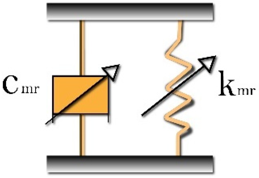
Figure 1. Simplified schematic for the assumed axial MRE-F absorber.
Actuators 14 00273 g001
Figure 2. The drilling system [21].
Actuators 14 00273 g002
Figure 3. The simplified system in the (a) axial direction and (b) torsional direction [21].
Actuators 14 00273 g003
Figure 5. Responses of the drilling system at Vd =7 mm/s and wd = 120 RPM: (a) The axial velocity response of the drill bit; (b) The rotary table and drill bit’s torsional velocity responses; (c) Applied weight on bit (WOBo) and weight on bit (WOB); (d) Rotary table’s applied torque and torque on bit (TOB); (e) Depth of cut; (f) Axial velocity response of the top suspension mass and drawworks Drum.
Actuators 14 00273 g005
Figure 6. Responses of the drilling system at Vd =7 mm/s, wd = 120 RPM, Kmr 0.001%, and Cmr 100%: (a) Bit and BHA axial velocity responses; (b) Bit and rotary table torsional velocity responses.
Actuators 14 00273 g006
Figure 7. Responses of the drilling system at Vd =7 mm/s and wd = 120 RPM with different Kmr and Cmr values: (a,c) Bit and BHA axial velocity responses. (b,d) Bit and rotary table torsional velocity responses.
Actuators 14 00273 g007aActuators 14 00273 g007b
Figure 8. The lowest smoothness index shown at Kmr 0.4% and Cmr 50% when considering both velocities to be of equal importance (i.e., α 1 = 0.5 ).
Actuators 14 00273 g008
Figure 9. The response is optimal when the smoothness index value is at its lowest, at Kmr 0.4%, Cmr 50%, and weighting factor α1 = 0.5, indicating a smooth drilling process with minimal fluctuations. (a) The axial velocity responses of the drill bit and BHA; (b) The rotary table and drill bit’s torsional velocity responses; (c) Applied weight on bit (WOBo) and weight on bit (WOB); (d) Rotary table’s applied torque and torque on bit (TOB); (e) Depth of cut; (f) Axial velocity response of the top suspension mass and drawworks Drum.
Actuators 14 00273 g009
Table 1. Axial absorber coefficients’ assumed values.
ParameterDescriptionValues
K m r Axial absorber stiffness coefficient initial value 7.54 × 10⁹ N/m
C m r Axial absorber damping coefficient initial value5.13 × 104 N s/m
Table 2. Parameters utilized in the simulation, Nomenclature and abbreviations [21].
ParametersDescriptionsValues
A p Cross section area of drill pipes 3.5 × 10⁻³ m2
boTerm of acceleration in a hyperbolic tangent function5.0
CVEffective damping due to fluid motion around the BHA3.75 N m s
CdsAxial-direction damping of drill string18,753 N s/m
CrtGearbox internal torsional damping0 N m s
DoDiameter of the drill line25 mm
d o BHA outer diameter 16 cm
d i BHA inner diameter 4 cm
EPElasticity modulus of drill pipe200 Gpa
EsElasticity modulus of drill line200 Gpa
FbrakeFriction force controlling the drawworks’ drum movement130 kN
GAcceleration due to gravity9.81 m/s2
I p Drill pipes polar moment of inertia I b = π 32 ( d o 4 d i 4 ) 1.23 × 10⁵ m4
JDWDrawworks drum inertia930 kg·m2
JmsDrawworks motor shaft inertia23 kg m2
JrtRotary table inertia930 kg m2
JmRotary table motor shaft inertia23 kg m2
JBHABottom-hole assembly inertia102.5 kg m2
JpipeDrill pipes’ inertia97.5 kg m2
JDrill string’s lumped inertia ( J = J B H A + 1 3 ( I p ρ b L P ) )135 kg m2
kcContact stiffness of the rock linear37.5 M·N/m
KmMotor constant of the drawworks system6 Vs
KmoMotor constant of the rotary table drive motor6 Vs
kdsDrill string’s effective axial stiffness ( k d s = E p A p L p )701.4 kN/m
KDrill string’s effective torsional stiffness ( K = G p I P L p )937.2 N m/rad
LpLength of the drill pipes1000 m
LbLength of the bottom-hole assembly200 m
LoDrill lines’ initial length20 m
LcArmature inductance of the drawworks0.005 H
LiArmature inductance of the rotary table0.005 H
l n Wear-flat length beneath each blade1.2 mm
mTopSuspension mass20,000 kg
mfMass of the fluid10,631 kg
mBHAMass of the BHA30,159.3 kg
mpipeMass of the drill pipes28,054.5 kg
maEffective mass of the drill string ( m a = m B H A + m f + 1 3 ( ρ b A p L p ) )50,142 kg
mbitMass of the bit120 Kg
nNumber of blades3.0
n D W Gearbox ratio of the drawworks’ motor14.30
NNumber of cycles during which the drill line moves between the traveling block and the crown block14
n o Gearbox ratio of the rotary table motor7.2
RbRadius of the bit22 cm
RDWRadius of the drawworks drum1050 mm
RmArmature resistance of the drawworks0.001 Ω
RmoRotary table armature resistance0.001 Ω
T f r The kinematic friction torque applied on drawworks drum through hand arm brake ( T f r = μ p F b r e a k R D W ) 40.95 KN·m
V C D Supply voltage to the rotary table DC motor ( V C D = K m o n o w d )542.9 V
V d Desired top mass axial velocity7 mm/s
V C Supply voltage to the drawworks drum DC motor ( V C = K m n D W W d d )7.42 V
w d Desired rotary table speed120 RPM
W d d Desired rotary table torsional velocity measured based on desired top mass axial veloc-ity ( W d d = N V d R D W ) 5.35 RPM
γ Spatial orientation of wear-flats1.3
εIntrinsic specific energy45 MPa
ζInclination of cutting force on cutting face0.8
μFriction coefficient0.3
μpDrawworks brake-pad friction coefficient0.3
ρ b Drill-string material density8000 kg/m3
ρ f Mud density1500 kg/m3
σRock normal contact stress45 Mpa
ACross section area of drill linesm2
C m r The values of the axial MRE-F absorber damping coefficient N·s/m
F h o o k The Hook load ( F h o o k = K s ( x T o p θ ˙ D W R D W N · t ) )N
f ( x ˙ a ) Heaviside function used to capture the Boundary condition of WOBf that depends on axial velocity in Phase II. -
f ( θ ˙ ) Heaviside function used to capture the TOB friction component sing variations during reverse the angular velocity in Phase II -
K m r The values of the axial MRE-F absorberthe stiffness coefficient N/m
K s The stiffness of the drill line ( K s = N E s A L ) [50].N/m
LThe length of drill lines from the crown block till the traveling Block
( L = L O + θ ˙ D W R D W N · t )
m
MRMagnetorheological materials belong to the category of smart materials -
MRFsmagnetorheological fluids material -
MREsmagnetorheological elastomers material -
MRE-Fhybrid magnetorheological elastomer-fluid -
PDCPolycrystalline diamond compact drill bits -
Smoothness Index ValueAn objective function can be established using the root mean square (RMS), which is a weighted function calculated from the percentage variation in both axial and torsional velocities with respect to their desired velocities -
T m o The torque at the motor shaft driving the rotary table ( T m o = K m o I m ) N·m
T L The torque applied on draw works drum from suspended weight ( T L = ( F h o o k N ) R D W ) N·m
T D W The torque transformed from the motor shaft to the draw works drum ( T D W = n D W K m I ) N·m
tnThe time required for the bit to rotate by an angle of 2 π n s
Tis the total drilling time s
TOBTorque On Bit N·m
TOBfTorque On Bit friction component N·m
TOBcTorque On Bit cutting component N·m
WOBWeight On Bit N
WOBfWeight On Bit friction component N
WOBcWeight On Bit cutting component N
x T o p , x ˙ T o p The Axial displacement and velocity of the suspension mass m,m/s
x a , x ˙ a The Axial displacement and velocity of the Bottom-Hole Assembly (BHA) m,m/s
x b i t , x ˙ b i t The Axial displacement and velocity of the PDC bit m,m/s
α 1 the weight factor ( 0 α 1 1 ) used in the Smoothness Index Value equation for both bit velocities’ responses -
θ D W , θ ˙ D W The angular displacement and velocity of draw works drum Rad,Rad/s
θ , θ ˙ The angular displacement and velocity of bit Rad,Rad/s
θ r t , θ ˙ r t The angular displacement and velocity of the rotary table. Rad,Rad/s
Disclaimer/Publisher’s Note: The statements, opinions and data contained in all publications are solely those of the individual author(s) and contributor(s) and not of MDPI and/or the editor(s). MDPI and/or the editor(s) disclaim responsibility for any injury to people or property resulting from any ideas, methods, instructions or products referred to in the content.