Abstract
Friction–inertia piezoelectric actuators can perform long-range positioning with nanometer resolution. However, friction and inertia are not easy to control and can influence the actuator’s performance. The present study proposes a friction–inertia-type piezoelectric XY positioning platform with a simple structure, which uses magnets to provide stable normal force and friction. Sliders and rails were used to provide long travel ranges of 80 mm and 70 mm in the X and Y directions, respectively. Compact optical encoders were installed on the platform to enhance the positioning accuracy. With a three-phase positioning strategy involving both stepping and closed-loop methods, the system achieved a positioning accuracy of 3 µm (0.03%) and a repeatability of 325 nm (0.0033%) over a 10 mm long travel range. The positioning resolution was 4.7 nm, which was primarily limited by optical encoder noise under the closed-loop control mode. An astigmatic optical profilometer was used for the wide-range and high-resolution surface imaging of the XY positioning platform.
1. Introduction
Piezoelectric actuators possess several key advantages, including compact size, easy control, rapid response, and an ability to enable precise positioning [1,2], which has contributed to their widespread use in fields such as precision measurement [3,4,5,6,7,8,9] and machining [10,11]. However, common piezoelectric stacks have a limited displacement-to-length ratio. For example, to achieve a maximum displacement of 100 μm, a 100 mm long piezoelectric stack is required, which may complicate applications that require compact size and rapid response. To amplify the displacement generated by piezoelectric stacks, various mechanical amplification structures, such as lever and rhombus mechanisms, have been proposed [12,13] and subsequently compared in the literature [14]. However, the travel range of these mechanical amplifiers is usually below 1 mm [15,16], which remains insufficient for applications requiring a centimeter travel range.
Long travel range and precise positioning can be achieved with stepping piezoelectric actuators, which can be mainly categorized as the inchworm type [17,18], the friction–inertia type [19,20,21,22,23,24,25,26,27,28], and the ultrasonic (resonant) type [29,30]. Ultrasonic-type actuators operate by driving piezoelectric elements at ultrasonic frequencies, typically ranging from several to several hundred kilohertz. This results in high-velocity motion, achieved through either elliptical trajectories or standing wave mechanisms. However, ultrasonic actuators are subject to limitations, including increased wear and thermal generation during high-frequency operation [31], as well as complexities related to control and preload adjustment [32]. Inchworm-type actuators perform a crawling motion by alternating the joint motion of the piezoelectric clamping and driving units, which offers the advantages of high resolution, large output force, and high speed [17,18]. However, the crawling motion typically requires the independent control of the clamping and driving units for clamping, feeding, and releasing motions to be realized, thus increasing system complexity and cost [33,34]. In contrast, friction–inertia-type actuators are based on a simpler principle where a piezoelectric driving unit undergoes slow and fast motions based on a sawtooth waveform. Specifically, the driving unit gradually pushes a slider forward, producing a small displacement and resulting in slow motion. The driving unit then rapidly draws back (fast motion), and the slider and load continue forward, overcoming the friction force on the interface between the driving unit and slider by virtue of inertia. As the slider slows down due to friction, this cycle repeats again, where the driving unit slowly pushes the slider before rapidly retracting. This friction–inertia mechanism requires the delicate control of both friction and inertia. Friction is influenced by the material type, surface roughness, preload force, manufacturing tolerances, and assembly accuracy; the surface conditions may also change over time due to long-term wear [35,36,37]. Inertia depends on the mass of both the slider and the load, which varies among applications. Consequently, the performance of the friction–inertia actuator may change based on the passage of time, slider position, load mass, and even movement direction [25,38,39].
A closed-loop control method can be used to increase the accuracy of stepping piezoelectric actuators by adding a displacement sensor, such as a capacitive displacement sensor [40,41], laser displacement sensor [42,43,44,45], laser interferometer [46], or linear optical encoder [45,47,48]. Capacitance sensors can offer sub-nanometer resolution but have a limited measurement range. Laser displacement can achieve nanometer resolution with a millimeter measurement range, but the bulky laser sensor head and long reference distance pose challenges to keeping the positioning system compact. Laser interferometers have the advantages of high resolution, a long measurement range, and fast measurement speed, but their high cost and complicated optical configuration make their integration into a compact piezoelectric actuator difficult. Optical encoders can theoretically achieve an infinite measurement range as their measurement range is only limited by the length of the linear scale. An interpolation method can also be used to realize nanometer resolution.
In the present study, we developed a friction–inertia-type XY positioning platform with long travel ranges of 80 mm and 70 mm in the X and Y directions, respectively. A novel magnet-based mechanism was proposed to simplify the widely used flexure mechanisms and provide multiple advantages, including a large payload capacity, compact size, and easy manufacturing and assembly [49]. To achieve precise and accurate positioning, we used an interpolated optical encoder with a maximum resolution of 1.22 nm and an interpolation factor of 16,384. Avoiding missing counts during fast movements when using an optical encoder with a friction–inertia-type actuator can be challenging. We used an embedded controller with a built-in field-programmable gate array (FPGA) for decoding in real time and established a three-phase positioning strategy to improve positioning speed without sacrificing resolution. The XY positioning platform was also integrated with an astigmatic optical profilometer to demonstrate its accuracy under a large scanning area.
2. Instrumentation
The driving principle and system configuration of the proposed XY positioning platform are described as follows:
2.1. Mechanical Design of XY Positioning Platform
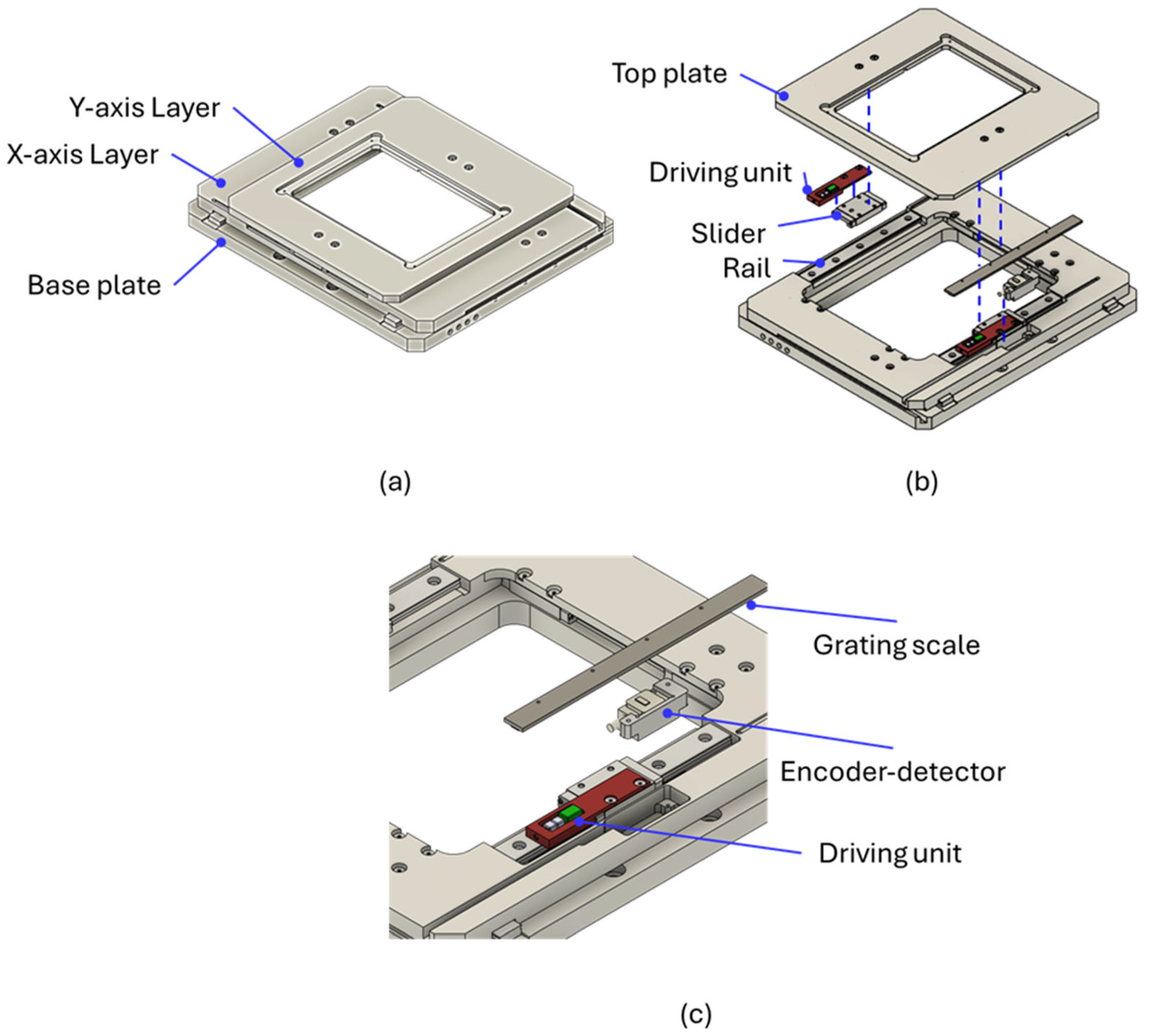
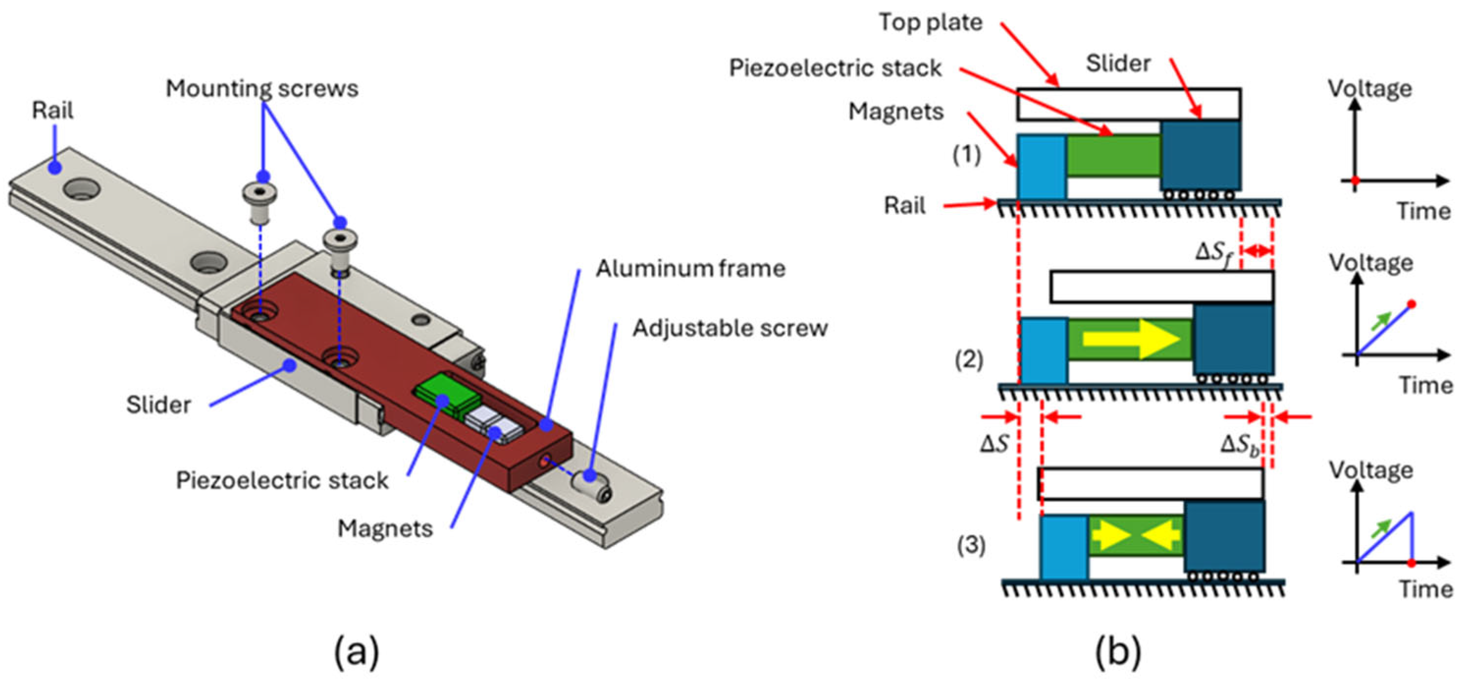
Figure 1a–c display the mechanical design and exploded view diagram of the XY positioning platform. The 275 mm × 220 mm × 34 mm platform consisted of a base plate, a Y-axis layer, and an X-axis layer, with an open center to fit standard inverted optical microscopes. Each moving layer was simultaneously driven by two parallel friction–inertia-type driving units, which were each installed on a slider and a rail (SSEL2BWN9, Misumi, Taipei, Taiwan). The parallelism of the two rails was a crucial consideration during assembly because misalignment could compromise the platform’s moving performance. The displacement of each moving layer was detected using a linear optical encoder, which included an encoder detector (Mercury II 6000, Celera Motion, Bedford, MA, USA) and a grating scale (TS-00140, Celera Motion). The encoder had an accuracy of ±1.5 μm and a resolution of 1.22 nm with an interpolation factor of 16,384. Figure 2a presents the configuration of the driving unit on the slider and rail, which consisted of a piezoelectric stack (PC4QM, Thorlabs, Newton, NJ, USA), two 5 mm cubic neodymium (NdFeB, Misumi, Taipei, Taiwan) magnets, and an aluminum frame installed on the slider with two mounting screws. The piezoelectric stack was fabricated from lead zirconate titanate (PZT); its material properties are detailed in Table 1. An adjustable spring screw was used to adjust the preload applied to the piezoelectric stack. The magnets were employed to generate a normal force on the rail, thereby producing friction. The chromium-coated magnets made direct surface contact with the stainless steel rail. According to the manufacturer’s specification, each magnet provides an attractive force of 8.9 N against a stainless steel surface. Consequently, the total normal force applied to the rail surface was 17.8 N. The normal force magnitude could be easily adjusted by varying the number and size of the magnets. The assembly process of the driving unit is outlined as follows:

Figure 1.
(a) Mechanical design and (b) exploded view diagram of XY positioning platform. (c) Magnified view highlighting driving unit and encoder.

Figure 2.
(a) The configuration and (b) operating principle of the friction–inertia-type driving unit.

Table 1.
Material properties of PC4QM piezoelectric stack.
- Thermal epoxy (EPO-TEK H74, Epoxy Technology, Billerica, MA, USA) was applied to the contact surfaces between the aluminum frame, piezoelectric stack, and magnets;
- The aluminum frame was mounted onto the slider and rail;
- The piezoelectric stack and magnets on the rail were carefully aligned, and a clamping screw was used to secure their positions temporarily;
- The aluminum frame was removed from the slider and rail;
- The aluminum frame was heated on a hot plate at approximately 100 °C for 25 min to cure the thermal epoxy;
- The aluminum frame was reinstalled onto the slider and rail;
- The clamping screw was removed, and the adjustable screw was used to apply a suitable preload to the piezoelectric stack.
Figure 2b illustrates the operating principle of the platform. Throughout the entire cycle of motion, the magnets maintained a magnetic normal force to remain in contact with the rail. Because the friction force between the magnets and the rail was greater than that between the slider and the rail, the slow elongation of the piezoelectric stack only shifted the slider by a displacement ∆Sf. When the piezoelectric stack rapidly shrunk, the slider only withdrew by a small displacement ∆Sb due to the inertia caused by the heavy top plate. Conversely, the impulse force overcame the friction between the magnets and the rail, causing the magnets to complete a single step displacement ∆S = ∆Sf − ∆Sb. For applications sensitive to magnetic fields, such as scanning electron microscope or transmission electron microscope systems, conventional springs can be used to replace the magnets to provide the required normal force.
2.2. System Configuration and Test Setup
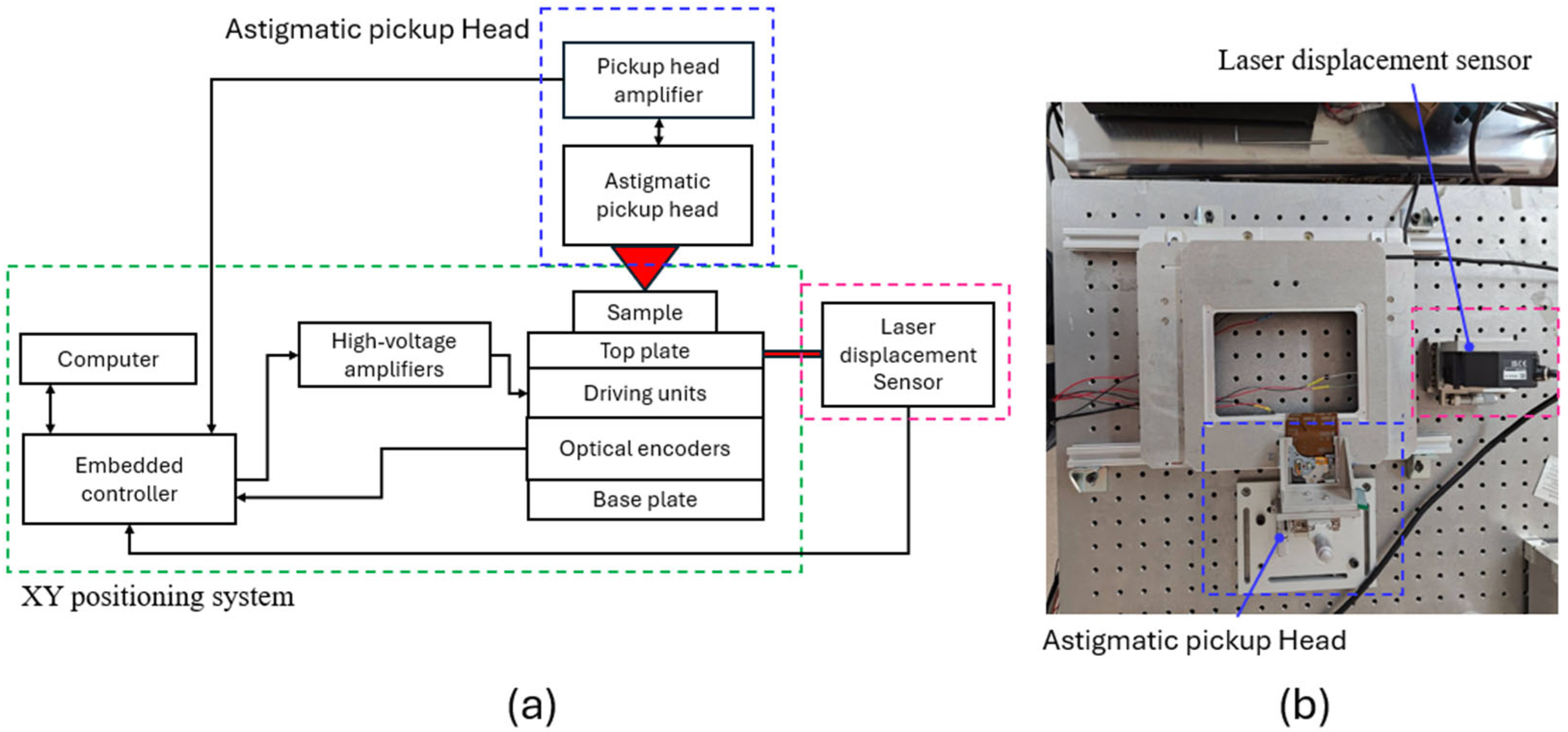
Figure 3a,b display the system configuration and a photograph of the XY positioning platform test setup. An embedded controller (sbRIO-9637, National Instruments, Austin, TX, USA) with a built-in FPGA was used to generate the XY driving signals, which were amplified with two high-voltage amplifiers (PD200, PiezoDrive, Newcastle, NSW, Australia) to control the XY driving units. Two optical encoders were used to detect the X and Y platform displacements, respectively, and their output signals were captured and decoded by the FPGA to calculate the XY positions. The existing displacements were compared with the target positions to determine the operation mode according to the positioning strategy. To verify optical encoder accuracy, a laser displacement sensor (LK-H052, Keyence, Osaka, Japan) was also utilized to measure platform displacement. Astigmatic optical profilometers have also been shown to have applications in verifying positioning performance [5,50,51]. The present study used a commercial astigmatic pickup head (TOP1100s, TopRay Technologies, Hsinchu, Taiwan) to measure the surface image of the sample carried by the XY positioning platform and a custom-made pickup head amplifier (TOP1100s driving circuit, OME Technology, Taoyuan, Taiwan) to drive the laser diode of the pickup head and generate the focus error signal VFES. During sample scanning along the XY plane, VFES was captured by the embedded controller to generate an image of the sample surface.

Figure 3.
(a) System configuration and (b) photograph of test setup.
2.3. Positioning Strategy
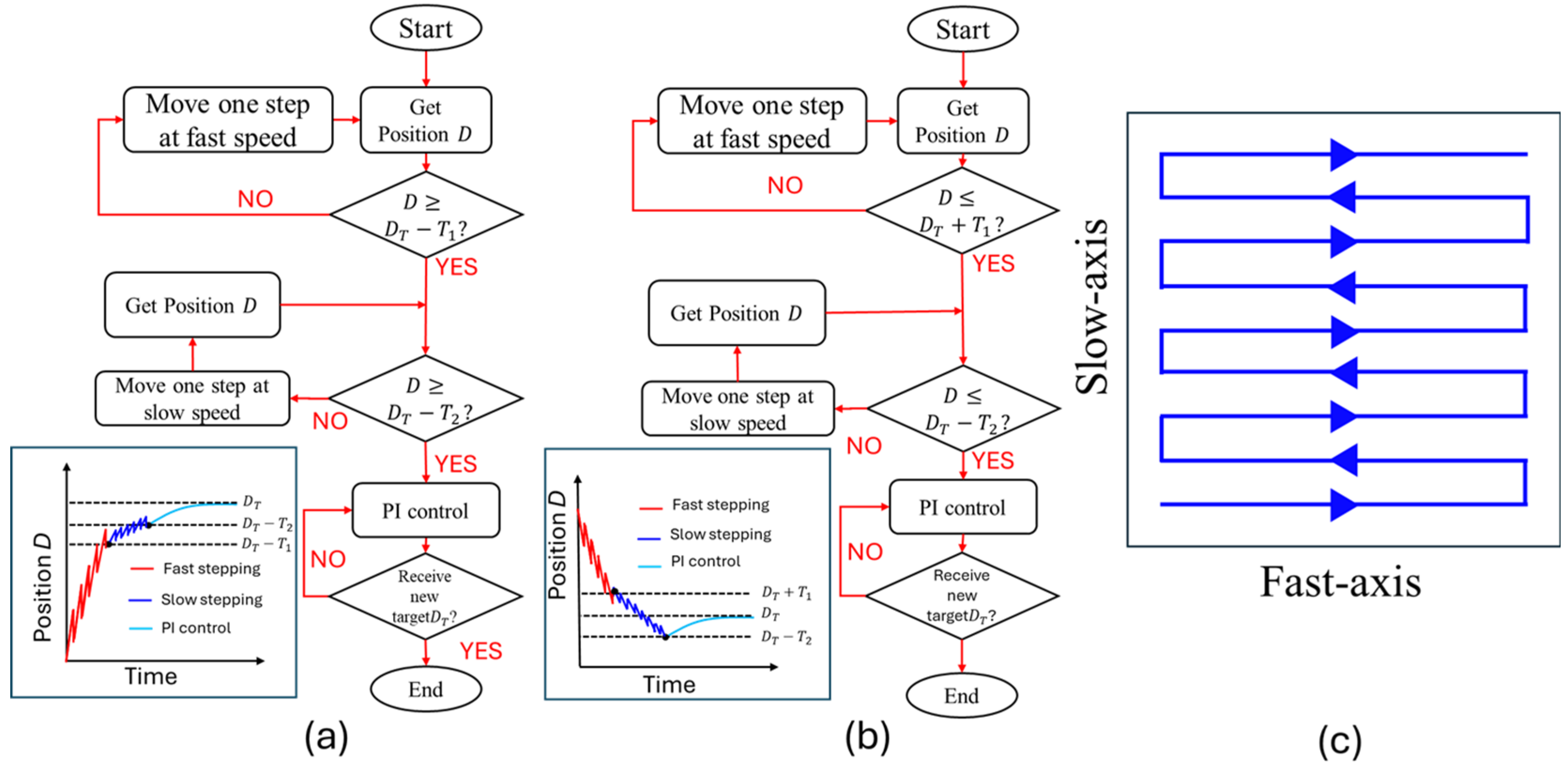
A three-phase positioning strategy, including fast-stepping, slow-stepping, and proportional–integral (PI) control modes, was proposed to improve positioning efficiency. The positioning processes for the forward and backward directions are illustrated in Figure 4a,b, respectively. After the user sets the target position DT, the current position D detected by the optical encoder is checked prior to each step. If the distance between the current and target positions is too large, the positioning platform is driven at a fast speed. Once the current position moves into the slow-stepping mode region (|D − DT| ≤ T1) defined by a threshold T1, both the driving voltage and frequency are reduced to achieve a higher resolution than is possible in the fast-stepping mode. During forward movement, the slow-stepping mode is switched to the PI mode when the distance between the current and target positions is less than the second threshold T2 (D ≥ DT − T2). During backward movement, the PI control mode is initiated when the current position overshoots the target position and reaches this mode’s lower region boundary (D ≤ DT − T2) because the piezoelectric stack can only perform forward extension. The experimental driving parameters were 150 V at 100 Hz and 15 V at 10 Hz for the fast- and slow-stepping modes, respectively, and the thresholds T1 and T2 were 30 µm and 4 µm, respectively. In the PI control mode, the positioning platform keeps tracking the existing target position until a new target position is set. A raster-scanning trajectory was used for optical profilometer imaging, as shown in Figure 4c. For each scan line, the three-phase positioning strategy was used for fast-axis scanning motion, whereas the position of the slow-axis was maintained using the PI control mode. Since the scanning speed was not constant, the VFES and XY positions were continuously recorded with a fixed sampling rate of 200 kHz for image mapping.
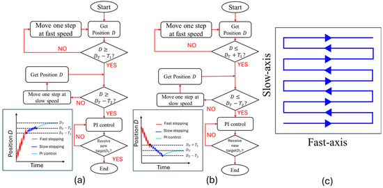
Figure 4.
Flow charts representing the three-phase positioning strategy for the (a) forward and (b) backward directions. (c) Raster-scanning trajectory.
3. Results and Discussion
The measurement accuracy of the optical encoder determines the positioning accuracy of the XY positioning platform. In the evaluation experiments, the displacement signal of the optical encoder was compared with that of the laser displacement sensor under different operation modes, and the applicability of the optical profilometer to large-area imaging applications was demonstrated.
3.1. Reciprocating Motion Driven by Triangular Waveform
Figure 5a,b show the respective X- and Y-axis displacements of the XY platform driven by the triangular waveform, which had a voltage range of 0 to 150 V and a frequency of 2 Hz. The black and red lines represent the displacements obtained by the laser displacement sensor and optical encoder, respectively. These results indicate that the displacement signal of the optical encoder was consistent with that of the laser displacement sensor. Additionally, the performance of the X- and Y-axis driving units was similar, with maximum travel ranges of 9.2 µm and 9.0 µm, respectively. The displacement curve was not linear due to the hysteresis effect of the piezoelectric stacks. Figure 5c displays the noise of the optical encoder when in a stationary position, which had a root-mean-square displacement fluctuation of approximately 4.7 nm.
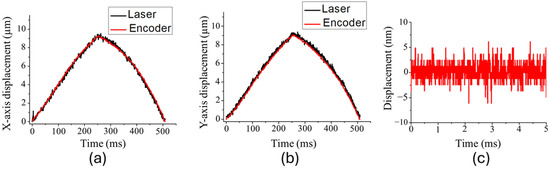
Figure 5.
(a) The X-axis and (b) Y-axis displacements of the XY platform driven by the triangular waveform with 150 V at 2 Hz. (c) The noise of the optical encoder when stationary.
3.2. Stepping Motion Driven by Sawtooth Waveform
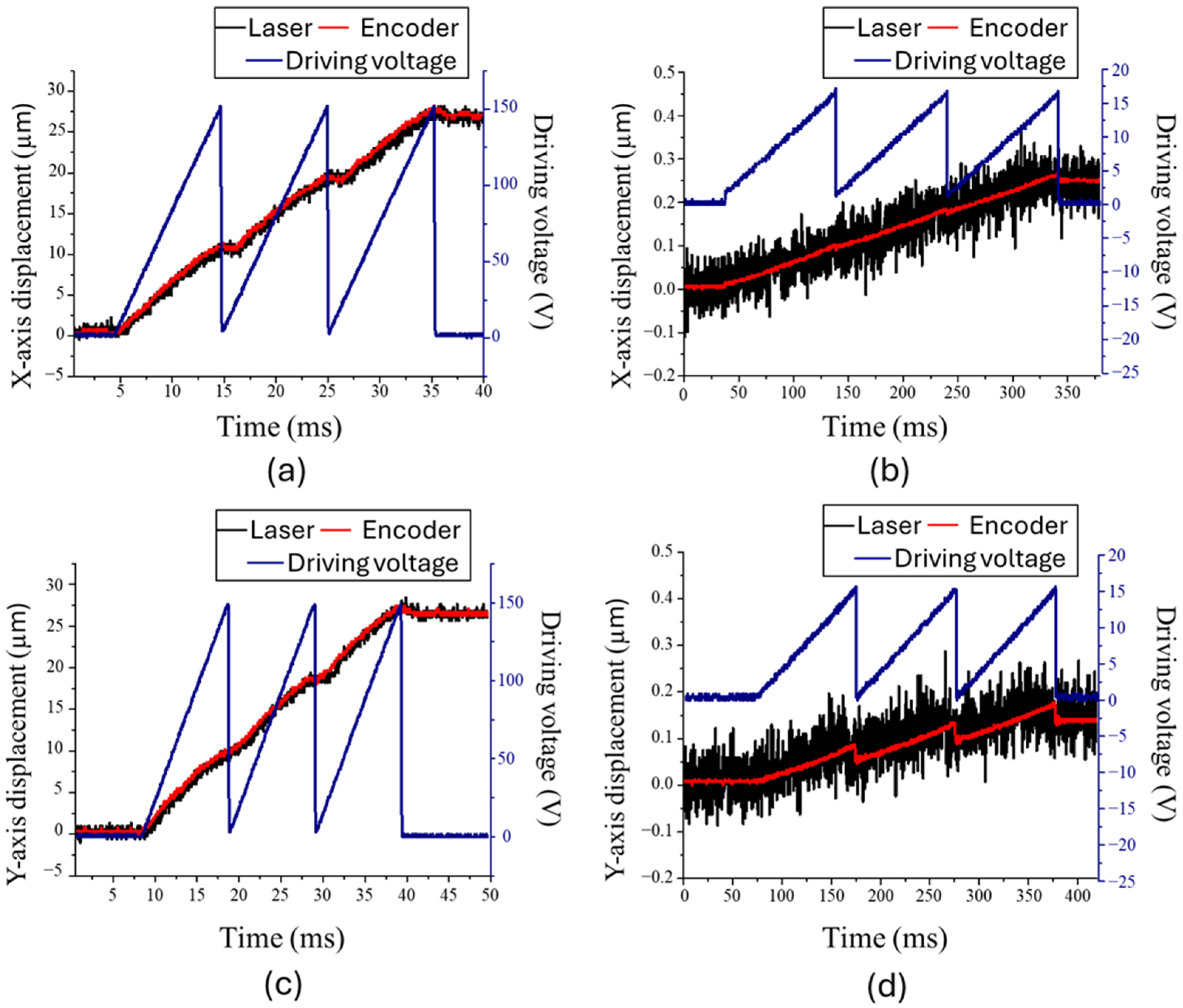
To examine optical encoder reliability during the fast withdrawal movement of the stepping motion, the XY positioning platform was driven by two separate sawtooth waveforms for the fast- and slow-stepping modes. The voltage ranges and frequencies of the waveforms for the fast and slow modes were 150 V at 100 Hz and 15 V at 10 Hz, respectively. Figure 6a,b show the respective X-axis displacements of three steps in the fast- and slow-stepping modes. The black and red lines represent the displacement measured by the laser displacement sensor and the optical encoder, respectively, and the blue line displays the driving signal. The displacements measured by the laser displacement sensor and optical encoder were consistent with each other. The average step sizes and speeds were 8.89 µm and 889 µm/s for the fast-stepping mode and 82 nm and 0.82 µm/s for the slow-stepping mode. The Y-axis displacements of three steps in the fast- and slow-stepping modes are shown in Figure 6c,d, respectively. The average step sizes and speeds were 8.76 µm and 876 µm/s for the fast-stepping mode and 44 nm and 0.44 µm/s for the slow-stepping mode. The average speeds of the X- and Y-axis displacements in the fast-stepping mode were very similar. However, in the slow-stepping mode, the withdrawal displacement ∆Sb was larger on the Y-axis than on the X-axis, because the X-axis driving units also carried the Y-axis layer, resulting in a large inertia force that reduced the withdrawal displacement on the X-axis. Therefore, the slow-stepping speed of the X-axis was faster than that of the Y-axis.
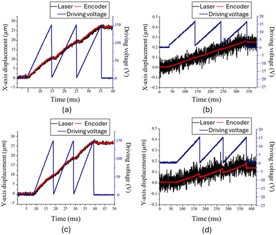
Figure 6.
X-axis displacement of three steps in (a) fast- and (b) slow-stepping modes. Y-axis displacement of three steps in (c) fast- and (d) slow-stepping modes.
3.3. Long-Range Positioning Using Three-Phase Strategy
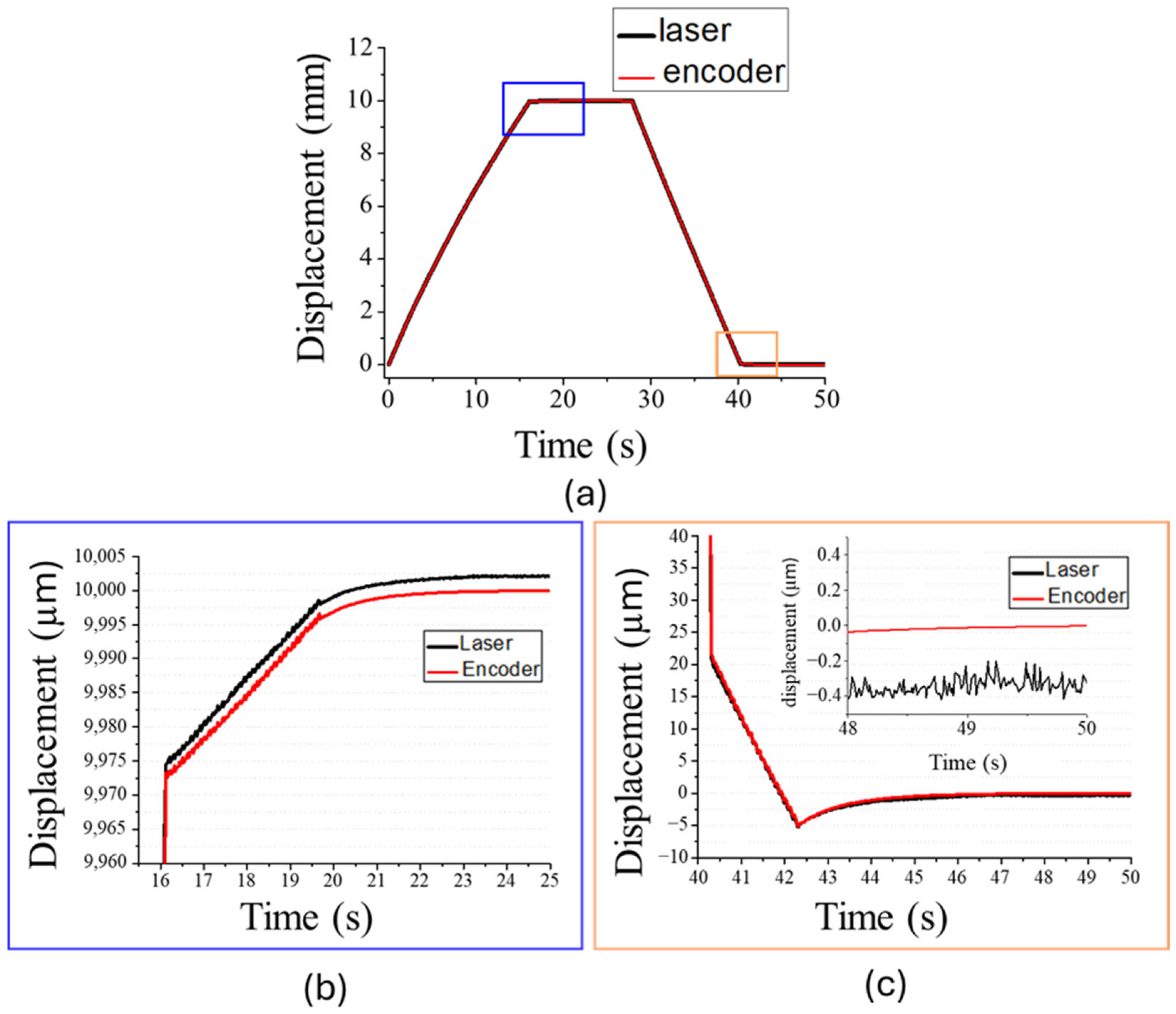
To facilitate the examination of long-range positioning accuracy, the XY positioning platform executed a 10 mm long back-and-forth movement along the X-axis using the three-phase positioning strategy, as shown in Figure 7a. The black and red lines represent the displacements measured by the laser displacement sensor and the optical encoder, respectively. First, the platform used the fast-stepping mode to approach the target position. Next, when the platform reached the threshold T1 of 30 µm, the operation mode was switched to slow stepping, as shown in Figure 7b. Finally, when the platform reached the threshold T2 of 4 µm, PI mode was activated. The results of this demonstration indicate that the platform can be stably maintained at the 10 mm position, as measured by the optical encoder. This experiment was repeated ten times, and a displacement deviation of 3.0 ± 2.5 µm (mean ± standard deviation) was observed between the laser displacement sensor and the optical encoder, which may be attributed to misalignment or manufacturing tolerance of the tape-type grating scale. Figure 7c displays the displacement when the platform was returning to its starting position. The platform consistently returned to its starting position with high precision, and the average displacement deviation between the laser displacement sensor and optical encoder was only 325 ± 307 nm. Asymmetry in the performance between the forward and backward movements was observed, likely due to mechanical structural asymmetries or assembly misalignment [25,39]. In the fast-stepping mode, the average speeds of the forward and backward movements were 612 µm/s and 798.47 µm/s, respectively, while in the slow-stepping mode, they were 6.48 µm/s and 13.07 µm/s. The current speed was primarily limited by the output update rate of the embedded controller, which constrained the frequency of the sawtooth driving waveform to 100 Hz. Upgrading to a high-speed embedded controller could potentially increase the fast-stepping frequency up to 1 kHz. Furthermore, the platform exhibited a maximum load capacity exceeding 15 kg. Without additional load, the maximum incline angle was approximately 10 degrees, limited by the platform’s own weight.
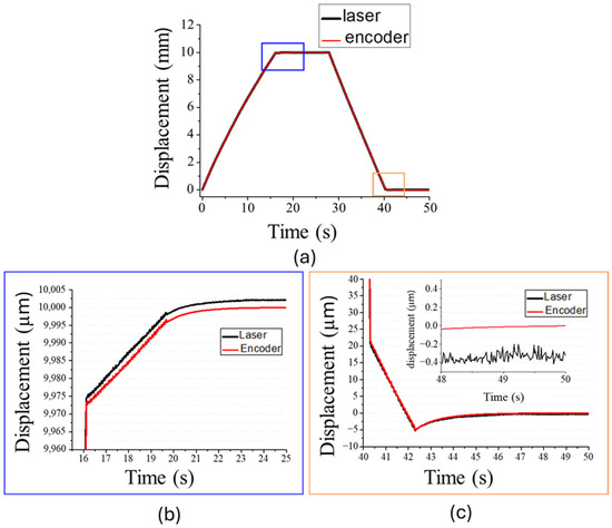
Figure 7.
(a) Displacement of 10 mm range back-and-forth positioning. Operation mode switches when (b) approaching 10 mm target and (c) returning to starting point.
3.4. Optical Profilometer Imaging
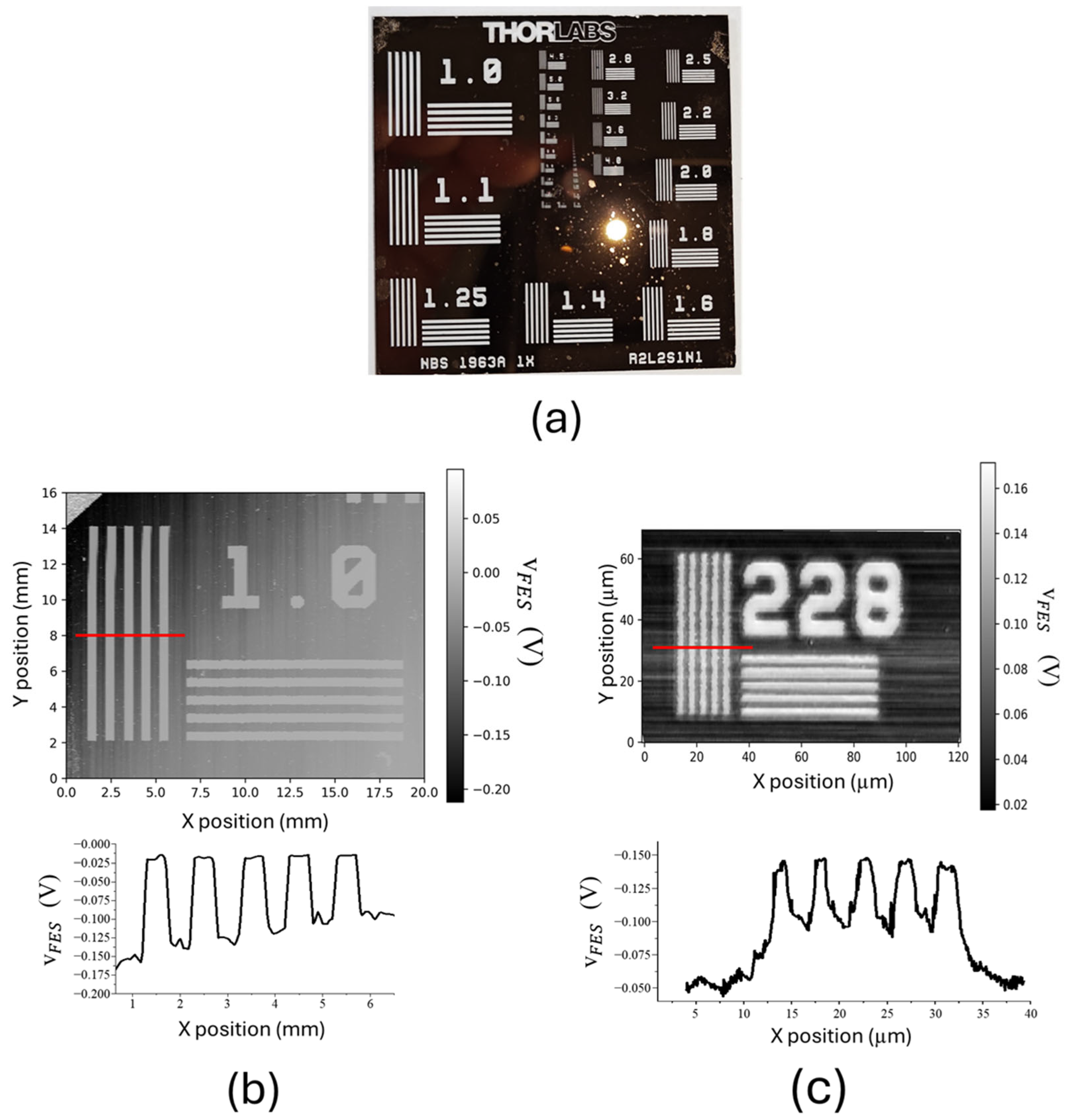
A standard sample (R2L2S1N1, Thorlabs, Newton, NJ, USA) was scanned using an optical profilometer. The sample featured a patterned chrome layer coated on a glass substrate, as shown in Figure 8a. Because of the large difference in reflectivity between the chrome layer and the glass substrate, the sample was able to provide clear contrast in VFES images. To examine both the accuracy and precision of the positioning platform, VFES images were scanned using a large scanning range of 20 mm × 16 mm (603 pixels × 583 pixels) and a small scanning range of 120 µm × 70 µm (600 pixels × 480 pixels), as shown in Figure 8a,b, respectively. The average imaging rates for the large and small regions were around 18.5 s/line (3 h/frame) and 7.5 s/line (1 h/frame), respectively. The bright patterns represent the glass surface without the chrome coating. The line patterns in Figure 8b are straight without distortion, indicating the long-range positioning accuracy of the platform. The average period of the line pattern, as shown in the cross-section, was 0.995 mm, which is consistent with the 1 mm in the sample specification. Figure 8c displays the smallest line pattern on the sample, which had a period of 4.38 µm according to the specification. The measured period shown in the cross-section was 4.37 µm, which is also consistent with the value of the specification.

Figure 8.
(a) Photograph of R2L2S1N1 sample. VFES images of optical profilometer with scanning ranges of (b) 20 mm × 16 mm and (c) 120 µm × 70 µm.
4. Conclusions
The present study proposed a novel design for a piezoelectric positioning platform with both a long travel range and high resolution. Combining an optical encoder with a closed-loop control method enabled the system to achieve high positioning accuracy. The current resolution under closed-loop control was 4.7 nm, which was limited by the optical encoder noise. The resolution was better than the optical diffraction limit for visible light and, therefore, is sufficient for optical profilometer use. However, the resolution was too low for use in more demanding precision applications, such as atomic force microscopy. For this reason, we plan to use an open-loop scanning mode to achieve sub-nanometer resolution. The optical encoder can be used to calibrate non-linear behavior due to the piezoelectric hysteresis effect [52].
Author Contributions
Conceptualization, E.-T.H.; methodology, Z.-R.G.; software, H.-S.T. and C.-S.C.; experiments, H.-S.T. and Z.-R.G., writing—original draft preparation, Z.-R.G.; writing—review and editing, H.-S.L.; supervision, H.-S.L.; funding acquisition, I.-S.H. All authors have read and agreed to the published version of the manuscript.
Funding
This research was funded by the National Science and Technology Council of Taiwan (NSTC 113-2221-E-002-110 and NSTC 113-2124-M-001-015).
Institutional Review Board Statement
Not applicable.
Informed Consent Statement
Not applicable.
Data Availability Statement
The original contributions presented in this study are included in the article.
Conflicts of Interest
The authors declare no conflicts of interest.
References
- Dong, S. Review on piezoelectric, ultrasonic, and magnetoelectric actuators. J. Adv. Dielectr. 2012, 2, 1230001. [Google Scholar] [CrossRef]
- Uchino, K. Piezoelectric actuators 2006. J. Electroceram. 2007, 20, 301–311. [Google Scholar] [CrossRef]
- Marchesi, A.; Umeda, K.; Komekawa, T.; Matsubara, T.; Flechsig, H.; Ando, T.; Watanabe, S.; Kodera, N.; Franz, C.M. An ultra-wide scanner for large-area high-speed atomic force microscopy with megapixel resolution. Sci. Rep. 2021, 11, 13003. [Google Scholar] [CrossRef] [PubMed]
- Yong, Y.K.; Moheimani, S.O.R. A compact XYZ scanner for fast atomic force microscopy in constant force contact mode. In Proceedings of the IEEE/ASME International Conference on Advanced Intelligent Mechatronics (AIM 2010), Montreal, QC, Canada, 6–9 July 2010; pp. 225–230. [Google Scholar]
- Liao, H.-S.; Cheng, S.-H.; Hwu, E.-T. Development of a Resonant Scanner to Improve the Imaging Rate of Astigmatic Optical Profilometers. IEEE/ASME Trans. Mechatron. 2021, 26, 1172–1177. [Google Scholar] [CrossRef]
- Lanzano, L.; Gratton, E. Orbital Single Particle Tracking on a Commercial Confocal Microscope Using Piezoelectric Stage Feedback. Methods Appl. Fluoresc. 2014, 2, 025001. [Google Scholar] [CrossRef]
- Wu, J.-W.; Liu, W.-C.; Fu, L.-C. Novel Vertical Scanning Algorithm with Advanced Control to Increase Range and Accuracy of Differential Confocal Microscopy. IEEE Trans. Instrum. Meas. 2022, 71, 5013510. [Google Scholar] [CrossRef]
- Song, H.; Fraanje, R.; Schitter, G.; Vdovin, G.; Verhaegen, M. Controller Design for a High-Sampling-Rate Closed-Loop Adaptive Optics System with Piezo-Driven Deformable Mirror. Eur. J. Control 2011, 17, 290–301. [Google Scholar] [CrossRef]
- Doret, S.C. Simple, Low-Noise Piezo Driver with Feed-Forward for Broad Tuning of External Cavity Diode Lasers. Rev. Sci. Instrum. 2018, 89, 023102. [Google Scholar] [CrossRef]
- Syahputra, H.P.; Ko, T.J.; Chung, B.M. Development of 2-Axis Hybrid Positioning System for Precision Contouring on Micro-Milling Operation. Int. J. Mech. Eng. Educ. 2014, 28, 691–697. [Google Scholar] [CrossRef]
- Liu, Y.; Zheng, Y.; Gu, Y.; Lin, J.; Lu, M.; Xu, Z.; Fu, B. Development of Piezo-Actuated Two-Degree-of-Freedom Fast Tool Servo System. Micromachines 2019, 10, 337. [Google Scholar] [CrossRef]
- Muraoka, M.; Sanada, S. Displacement amplifier for piezoelectric actuator based on honeycomb link mechanism. Sens. Actuators A Phys. 2010, 157, 84–90. [Google Scholar] [CrossRef]
- Ouyang, P.R.; Zhang, W.J.; Gupta, M.M. A new compliant mechanical amplifier based on a symmetric five-bar topology. J. Mech. Des. 2008, 130, 104501. [Google Scholar] [CrossRef]
- Muhith, S.; Upadhya, A.R.; Navin, K.P.; Kulkarni, S.M.; Rao, M. Recent trends in piezoelectric actuators for precision motion and their applications: A review. Smart Mater. Struct. 2021, 30, 013002. [Google Scholar] [CrossRef]
- Zhu, X.; Xu, X.; Wen, Z.; Ren, J.; Liu, P. A novel flexure-based vertical nanopositioning stage with large travel range. Rev. Sci. Instrum. 2015, 86, 105112. [Google Scholar] [CrossRef]
- Choi, S.B.; Han, S.S.; Han, Y.M.; Thompson, B.S. A magnification device for precision mechanisms featuring piezoactuators and flexure hinges: Design and experimental validation. Mech. Mach. Theory 2007, 42, 1184–1198. [Google Scholar] [CrossRef]
- Chen, Q.; Yao, D.-J.; Carman, G.P. Mesoscale Actuator Device: Micro Interlocking Mechanism to Transfer Macro Load. Sens. Actuators A Phys. 1999, 73, 30–36. [Google Scholar] [CrossRef]
- Tian, X.; Quan, Q.; Wang, L.; Su, Q. An Inchworm Type Piezoelectric Actuator Working in Resonant State. IEEE Access 2018, 6, 18975–18983. [Google Scholar] [CrossRef]
- Wang, L.; Wang, H.; Jiang, J.; Luo, T. Development of a Novel Piezoelectric Actuator Based on Stick-Slip Principle by Using Asymmetric Constraint. Micromachines 2023, 14, 1140. [Google Scholar] [CrossRef]
- Wan, N.; Wen, J.; Hu, Y.; Kan, J.; Li, J. A parasitic type piezoelectric actuator with an asymmetrical flexure hinge mechanism. Microsyst. Technol. 2019, 26, 917–924. [Google Scholar] [CrossRef]
- Zhang, Y.; Peng, Y.; Sun, Z.; Yu, H. A Novel Stick–Slip Piezoelectric Actuator Based on a Triangular Compliant Driving Mechanism. IEEE Trans. Ind. Electron. 2019, 66, 5374–5382. [Google Scholar] [CrossRef]
- Cheng, T.; He, M.; Li, H.; Lu, X.; Zhao, H.; Gao, H. A Novel Trapezoid-Type Stick–Slip Piezoelectric Linear Actuator Using Right Circular Flexure Hinge Mechanism. IEEE Trans. Ind. Electron. 2017, 64, 5545–5552. [Google Scholar] [CrossRef]
- Xu, Z.; Huang, H.; Dong, J. A stick-slip piezoelectric actuator with measurable contact force. Mech. Syst. Signal Process. 2020, 144, 106881. [Google Scholar] [CrossRef]
- Li, J.; Zhou, X.; Zhao, H.; Shao, M.; Hou, P.; Xu, X. Design, Analysis and Experimental Performance of a Bionic Piezoelectric Rotary Actuator. Smart Mater. Struct. 2015, 24, 06500. [Google Scholar] [CrossRef]
- Huang, H.; Liu, Y.; Xu, Z.; Li, X.; Wang, K. Achieving High Consistency in Forward and Reverse Motions of Stick-Slip Piezoelectric Actuator by a Symmetrical Structure and Optimized Installation Method. Microsyst. Technol. 2023, 29, 1343–1355. [Google Scholar] [CrossRef]
- Huang, H.; Zhao, H.; Yang, Z.; Mi, J.; Fan, Z.; Wan, S.; Shi, C.; Ma, Z. A Novel Driving Principle by Means of the Parasitic Motion of the Microgripper and Its Preliminary Application in the Design of the Linear Actuator. Rev. Sci. Instrum. 2012, 83, 055002. [Google Scholar] [CrossRef] [PubMed]
- Xing, S.; Gao, J.; Lu, T.; Zhou, L.; Zhang, J.; Li, X.; Tian, H. A three-legged stick-slip piezoelectric actuator inspired by haystack unloading device and its driving method. Results Eng. 2025, 26, 105146. [Google Scholar] [CrossRef]
- Koc, B.; Delibas, B. Impact force analysis in inertia-type piezoelectric motors. Actuators 2023, 12, 52. [Google Scholar] [CrossRef]
- Delibas, B.; Koc, B. Single crystal piezoelectric motor operating with both inertia and ultrasonic resonance drives. Ultrasonics 2024, 136, 107140. [Google Scholar] [CrossRef]
- Naz, S.; Xu, T.-B. A comprehensive review of piezoelectric ultrasonic motors: Classifications, characterization, fabrication, applications, and future challenges. Micromachines 2024, 15, 1170. [Google Scholar] [CrossRef]
- Li, J.; Huang, H.; Morita, T. Stepping piezoelectric actuators with large working stroke for nano-positioning systems: A review. Sensors Actuators A Phys. 2019, 292, 39–51. [Google Scholar] [CrossRef]
- Peng, Y.; Peng, Y.; Gu, X.; Wang, J.; Yu, H. A review of long range piezoelectric motors using frequency leveraged method. Sensors Actuators A Phys. 2015, 235, 240–255. [Google Scholar] [CrossRef]
- Ma, L.; Xiao, J.; Zhou, S.; Sun, L. A Piezoelectric Inchworm Actuator of Linear Type Using Symmetrical Lever Amplification. Proc. Inst. Mech. Eng. Part N 2014, 229, 172–179. [Google Scholar] [CrossRef]
- Ma, L.; Jiang, C.; Xiao, J.; Wang, K. Design and Analysis of a Piezoelectric Inchworm Actuator. J. Microbio. Robot. 2014, 9, 11–21. [Google Scholar] [CrossRef]
- Yamaguchi, T.; Adachi, K.; Ishimine, Y.; Kato, K. Wear mode control of drive tip of ultrasonic motor for precision positioning. Wear 2004, 256, 145–152. [Google Scholar] [CrossRef]
- Lv, Q.; Yao, Z.; Jin, Y.; Liu, B. Wear evaluation of a linear piezoelectric ultrasonic motor considering temperature effect. Ultrasonics 2022, 126, 106822. [Google Scholar] [CrossRef] [PubMed]
- Qiao, G.; Zhang, Y.; Cao, Q.; Wang, C.; Chen, Z.; Gong, G.; Yang, H.; Han, D. An Ultradurable Piezoelectric Inertia Actuator via Wear-Adaptive Mechanism. IEEE Trans. Ind. Electron. 2025, Early Access. [Google Scholar] [CrossRef]
- Tang, J.; Wei, J.; Wang, Y.; Xu, Z.; Huang, H. A Novel Rotation-Structure Based Stick-Slip Piezoelectric Actuator with High Consistency in Forward and Reverse Motions. Actuators 2021, 10, 189. [Google Scholar] [CrossRef]
- Xu, Z.; Li, X.; Wang, K.; Liang, T.; Dong, J.; Huang, H. A stick–slip piezoelectric actuator with high consistency in forward and reverse motions. Rev. Sci. Instrum. 2020, 91, 105005. [Google Scholar] [CrossRef]
- Zhong, B.; Zhu, J.; Jin, Z.; He, H.; Wang, Z.; Sun, L. A large thrust trans-scale precision positioning stage based on the inertial stick–slip driving. Microsyst. Technol. 2019, 25, 3713–3721. [Google Scholar] [CrossRef]
- Fan, K.; Shi, R.; Feng, Z. IDM-Assisted Capacitive Displacement Sensor for Large-Range, High-Precision Positioning Systems. IEEE Trans. Ind. Electron. 2024, 71, 8047–8057. [Google Scholar] [CrossRef]
- Li, J.; Zhou, X.; Zhao, H.; Shao, M.; Li, N.; Zhang, S.; Du, Y. Development of a Novel Parasitic-Type Piezoelectric Actuator. IEEE/ASME Trans. Mechatron. 2017, 22, 541–550. [Google Scholar] [CrossRef]
- Guo, Z.; Tian, Y.; Zhang, D.; Wang, T.; Wu, M. A novel stick-slip based linear actuator using bi-directional motion of micropositioner. Mech. Syst. Signal Process. 2019, 128, 37–49. [Google Scholar] [CrossRef]
- Chang, Q.; Liu, Y.; Deng, J.; Zhang, S.; Chen, W. Design of a precise linear-rotary positioning stage for optical focusing based on the stick-slip mechanism. Mech. Syst. Signal Process. 2022, 165, 108398. [Google Scholar] [CrossRef]
- Tian, X.; Chen, W.; Zhang, B.; Liu, Y. Restraining the backward motion of a piezoelectric stick-slip actuator with a passive damping foot. IEEE Trans. Ind. Electron. 2022, 69, 10396–10406. [Google Scholar] [CrossRef]
- Boudaoud, M.; Liang, S.; Lu, T.; Oubellil, R.; Régnier, S. Voltage/frequency rate dependent modeling for nano-robotic systems based on piezoelectric stick-slip actuators. In Proceedings of the IEEE International Conference on Intelligent Robots and Systems, Daejeon, Republic of Korea, 9–14 October 2016; pp. 5297–5303. [Google Scholar]
- Oubellil, R.; Voda, A.; Boudaoud, M.; Régnier, S. Mixed stepping/scanning mode control of stick-slip SEM-integrated nano-robotic systems. Sens. Actuators A Phys. 2019, 285, 258–268. [Google Scholar] [CrossRef]
- Hwu, E.-T.; Nazaretski, E.; Chu, Y.S.; Chen, H.-H.; Chen, Y.-S.; Xu, W.; Hwu, Y. Design and characterization of a compact nano-positioning system for a portable transmission x-ray microscope. Rev. Sci. Instrum. 2013, 84, 123702. [Google Scholar] [CrossRef] [PubMed]
- Liao, H.S.; Werner, C.; Slipets, R.; Larsen, P.E.; Hwang, I.S.; Chang, T.J.; Danzebrink, H.U.; Huang, K.Y.; Hwu, E.T. Low-cost, open-source XYZ nanopositioner for high-precision analytical applications. HardwareX 2022, 11, e00317. [Google Scholar] [CrossRef] [PubMed]
- Liao, H.-S.; Huang, G.-T.; Tu, H.-D.; Lin, T.-H.; Hwu, E.-T. A novel method for quantitative height measurement based on an astigmatic optical profilometer. Meas. Sci. Technol. 2018, 29, 10. [Google Scholar] [CrossRef]
- Liao, H.S.; Huang, Y.K.; Syu-Gu, J.Y.; Hwu, E.T. Real-Time Reflectance Measurement Using an Astigmatic Optical Profilometer. Sensors 2022, 22, 6242. [Google Scholar] [CrossRef]
- Liao, H.-S.; Guo, Z.-R.; Tan, H.-S.; Huang, K.-Y.; Hwang, I.-S.; Hwu, E.-T. Astigmatic detection system with feedback mechanism for calibrating driving waveform of piezoelectric actuators. IEEE Trans. Instrum. Meas. 2023, 72, 1007907. [Google Scholar] [CrossRef]

Disclaimer/Publisher’s Note: The statements, opinions and data contained in all publications are solely those of the individual author(s) and contributor(s) and not of MDPI and/or the editor(s). MDPI and/or the editor(s) disclaim responsibility for any injury to people or property resulting from any ideas, methods, instructions or products referred to in the content. |
© 2025 by the authors. Licensee MDPI, Basel, Switzerland. This article is an open access article distributed under the terms and conditions of the Creative Commons Attribution (CC BY) license (https://creativecommons.org/licenses/by/4.0/).