1. Introduction
The traditional hydraulic system adopts centralized valve control, with multiple actuators sharing the same valve group, which has problems such as high energy loss and action interference. With the development of electronic control technology and energy-saving needs, independent metering systems (IMSs) have emerged [
1,
2,
3]. By equipping each actuator (hydraulic cylinder, motor, etc.) with independent valve groups and sensors, flow and pressure can be accurately regulated, solving the efficiency and flexibility bottlenecks of traditional systems [
4,
5]. IMS is widely used in construction machinery, such as excavators and cranes, to reduce fuel consumption by independently controlling the actions of the boom, bucket, etc., combined with energy recovery technology, thus realizing high-precision pressure control in industrial equipment (injection molding machines, machine tools) to improve product quality. The aerospace industry utilizes its redundant design to enhance reliability. In addition, IMS optimizes energy utilization efficiency in the field of new energy (wind power variable pitch, wave energy generation). This system can save more than 30% energy and has the advantages of fast response and flexible operation, promoting the transformation towards intelligent and green hydraulic technology [
6,
7].
With the continuous advancement of modern industrial automation, hydraulic drive systems have become widely adopted across various fields, attributed to their high power density and excellent dynamic performance. At present, digital valves are extensively utilized in heavy machinery, aerospace, military equipment, and other critical domains [
8,
9,
10,
11,
12]. A hydraulic cylinder serves as the core actuator in the hydraulic drive system, with the precision and response speed of its position control directly affecting the performance and stability of the entire system. However, the traditional digital valve primarily relies on the incremental digital valve as the main operative component, thereby resulting in problems such as core control components’ susceptibility to damage, heightened sensitivity to oil cleanliness and substantial volume, etc. [
13]. Moreover, in scenarios where precision requirements are less stringent and cost control is a priority, incremental digital valves may not represent the optimal choice. High-speed on-off valves can be used as an alternative to digital valves.
The management of high-speed digital switching valves necessitates mutual interaction among different tempering signals. The commonly employed modulation signals include pulse width modulation (PWM), pulse number modulation (PNM), and pulse code modulation (PCM) [
14,
15,
16]. Numerous scholars at home and abroad have explored the utilization of high-speed on-off valves for controlling hydraulic cylinder displacement. Reference [
17] presented a pre-excitation control algorithm, achieving an 80.0% increase in the linear area of the flow characteristics and a 23% reduction in the adjustment time of the HSV control system. Reference [
18] realized compound control of hydraulic cylinder speed and pressure, leveraging a reverse step method within high-speed on-off valves, which contributes to the enhancement of position tracking accuracy. Reference [
19] introduced a hydraulic stepping drive technology based on a high-speed on-off valve set and two miniature plunger cylinders. At a load of 3 KN, the drive, with a stroke of 50 μm, exhibited an 11.58% reduction in maximum error. Reference [
20] substituted the check valve with two digital valves to facilitate asymmetric flow compensation, thereby enabling high-precision control of hydraulic cylinder displacement. In order to analyze the position control of hydraulic cylinders governed by high-speed switch valves and ensure precise positioning, Reference [
21] proposed a composite algorithm of PD, velocity feedforward displacement feedback, and pulse width modulation (PWM) control. Reference [
22] adopted a parallel digital valve with a servo valve group and a hydraulic system combined with the sliding mode control strategy. This arrangement not only maintained the uniformity of switching between valves but also effectively controlled the displacement of the spool of the slide valve.
The aforementioned research on the control of hydraulic cylinder displacement, mediated by a digital valve, predominantly uses diverse signal modulation schemes in conjunction with the rapid response speed and high flow accuracy of high-speed on-off valves, with the objective of a broad range of adjustable flow outputs, ultimately facilitating precise control of the actuator position. Nevertheless, due to the inherent binary nature of high-speed on-off valves, flow or pressure pulsations will inevitably induce vibrations in the hydraulic cylinder. Furthermore, proportional electro-hydraulic systems exhibit intricate nonlinear attributes [
23], and the commonly deployed proportional valve demonstrates extreme sensitivity to oil, triggering time variance system behavior [
24]. When employing PID control, accurately capturing the nonlinear traits of the hydraulic system proves challenging; moreover, in the presence of external disturbances and large-scale displacement adjustments, this approach yields subpar system responses, which potentially undermines both position control precision and overall system stability.
The main principle of sliding mode structure control technology centers on the design of a stable sliding surface that directs the system towards and along the sliding surface to reach the origin, enabling rapid convergence to the desired state [
25]. The sliding mode control (SMC) technology embodies a discontinuous nonlinear control technology that is impervious to the parameters of the controlled object or the operational environment. In response to the intricacies of motion disturbance and low loading accuracy in electro-hydraulic load simulation systems, Reference [
26] introduced a sliding mode self-disturbance rejection composite controller, which can markedly diminish system chattering, solve problems of fixed-time convergence, and augment system loading performance and disturbance rejection. Additionally, in order to enhance the force control performance and anti-interference robustness of the electro-hydraulic servo material testing machine, Reference [
27] proposed an integral sliding film control method predicated on feedback linearization, thereby achieving high-precision tracking of the machines’ force control system. Moreover, to mitigate the impact of unknown disturbances on the control performance of hydraulic servo systems, Reference [
28] presents a sliding mode variable structure control utilizing space vector adjustment technology. Experimental validations underscore that this designed controller proficiently suppresses the influence of large system disturbances, enhancing both the control accuracy and system response dynamics. Although the above research results have strong robustness to the composite interference caused by internal parameter changes and external disturbances in the system, they all elucidate proposed constraints.
In the domain of control science, controller design is prone to be constrained by modeling techniques. Mathematical models established based on actual systems are frequently accompanied by unpredictability in controlled object, including parameter uncertainty, and uncertainties in nonlinear unknown functions, complicated structures, and unmodeled dynamics. To address these issues, neural network control is a highly effective tool for system manipulation. Reference [
29] used an RBF neural network for situation estimation without the need for prior knowledge of uncertainties, ensuring that the robotic arm system converges with a finite time error. For electro-hydraulic servo systems, Reference [
30] proposed the combination of a nonlinear neural network (NN) and error sign continuous robust integral (RISE) feedback controller, enabling online parameter updates and asymptotic stability of the system. Reference [
31] introduced an extended state observer, which equates the uncertainty and external disturbances in digital hydraulic cylinders to integrated disturbances and employs neural network model reference adaptive control for disturbance rejection. Concerning the difficulty in drift estimation of navigation marks, Reference [
32] designed a fractional gradient based on momentum RBF neural network (FOGDM-RBF); and through confirmation of its convergence, it was used for estimating the drift trajectory of navigation marks across diverse geographical locations. Furthermore, to realize more accurate tracking, Reference [
33] designed a robust adaptive RBF neural network compensator to approximate and compensate for TDE errors, ensuring the asymptotic stability of the system according to the Lyapunov criterion. Reference [
34] proposed several novel hybrid adaptive neural fuzzy inference system methods as prediction models for estimating the downstream scour depth of gates. By removing some prediction variables, three input variable combinations were prepared to obtain a reliable prediction model. Reference [
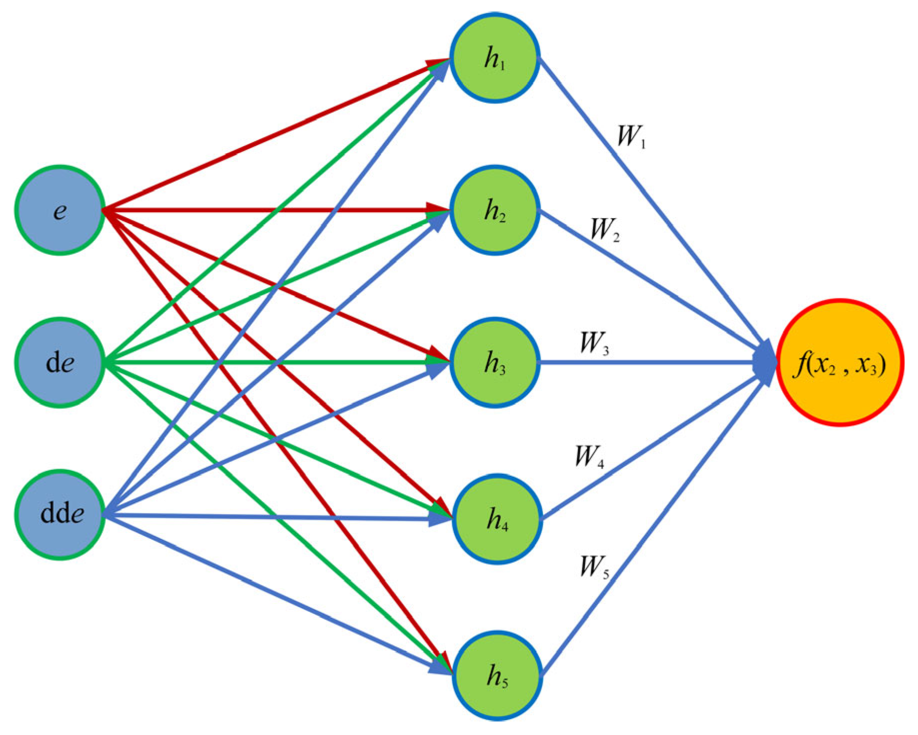
35] demonstrated the application of an adaptive neural fuzzy inference system (ANFIS) combining particle swarm optimization, ant colony optimization, differential evolution, and genetic algorithm. The prediction performance and related uncertainties of scour depth under different scour conditions, including active beds and clean water, were evaluated. The uncertainty results showed that it was related to both the model structure and the combination of input variables. The RBF neural network, through the local response characteristics of radial basis functions, can achieve efficient nonlinear approximation with fewer hidden layer nodes. Compared with traditional fully connected networks (such as the BP network), it has a faster training speed and more stable convergence, making it especially adept at handling data with significant local features and dynamic system modeling. RBF neural network control has higher structural parallelism, efficient computing power, and the ability to preserve system information through neurons and neural weights.
The extended state observer (ESO) excels in estimating and compensating for system disturbances without relying on the specific model of the research object and disturbance. This capability significantly alleviates the negative effects of disturbances on controller performance, making it an indispensable tool adopted in high-precision control exploration of electro-hydraulic position servo systems [
36,
37]. In order to address the challenges of uncertainty, nonlinearity, and interference in robots, Reference [
38] proposed an integrated sliding mode control (ISMC) based on multi input multi output ESO, which effectively solves the problems of uncertainty, nonlinearity, and interference in robotic systems through disturbance estimation and active compensation, dynamic sliding mode surface design, and low gain switching. Concurrently, a formation control strategy utilizing a linear extended state observer (LESO) and an estimated minimum learning parameter (EMLP) neural network was proposed in Reference [
39] to address the issues of wind influence and model uncertainty. An adaptive controller based on LESO was designed to monitor and counteract system disturbances, thereby maintaining stability and accuracy of the entire formation flight system. In the context of unmanned surface vehicles (USVs) striving for high-precision trajectory tracking, Reference [
40] presented a control strategy using predetermined time tracking control technology and established a predetermined time extended state observer to promptly and accurately reconstruct unmeasurable velocities and lumped disturbances, with the aim to monitor swift error convergence within the designated timeframe. Given their profound effectiveness at mitigating disturbance impacts on the controlled system, extended state observers have garnered widespread adoption within electro-hydraulic servo systems.
In order to tackle existing problems, this paper offers a digital valve-controlled hydraulic cylinder position control method that incorporates load port neural network sliding mode control. The variable structure sliding mode controller deployed in this method exhibited superior performance in regulating the hydraulic system with high-order nonlinear strong coupling and external interference. For the streamlining of the hydraulic control system model, the neural network algorithm with self-learning and self-adapting ability is integrated, which simplifies the hydraulic system model and notably enhances its control properties. The conventional valve-controlled hydraulic system relies on the direction valve to reverse hydraulic systems with the presence of throttling loss in the oil inlet and outlet, which in turn leads to the substantial energy consumption and compromised efficiency of the whole system. Based on this, this paper adopts the independent load port as the hydraulic control system [
41,
42].
The asymmetric hydraulic cylinder with differing structural parameters in its two cavities makes the modeling process complex. For the previous research on the digital valve-controlled hydraulic cylinder, the symmetric cylinder was mainly utilized as the control object. This paper simplifies the mathematical model based on the existing model of the digital valve-controlled asymmetric hydraulic cylinder.
In this study, the mathematical model of the hydraulic cylinder system is first established, and then analysis of its nonlinear characteristics and disturbance effects is performed to streamline the system. Subsequently, the high-order sliding mode controller in conformity with the provisions of sliding mode control is devised. With the assistance of the simplified model, the radial basis neural network is introduced to approximate the uncertainty aspect of the model online. Finally, the output of the controller is converted into signals that can be effectively used by high-speed switches. The efficacy of the proposed method is verified through simulation and experiment. As shown in the results, the proposed control strategy can significantly improve the accuracy, system response speed, and stability of hydraulic cylinder position control while exhibiting excellent robustness and adaptability under complex load and disturbance conditions.
The main contributions of this research can be categorized into the following three aspects:
An innovative sliding mode control method is incorporated for the independent metering control system. The RBF neural network and generalized extended state observer are introduced into the model reference adaptive controller, which significantly enhances the accuracy and robustness of position tracking control.
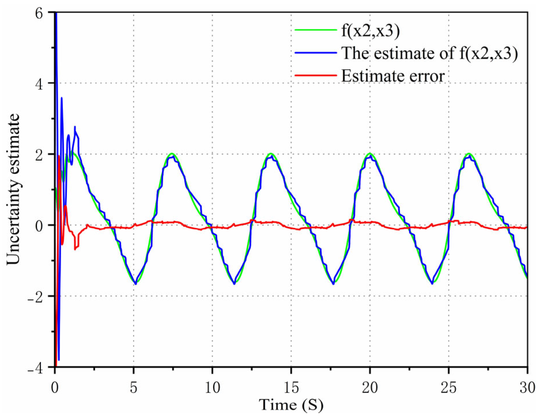
The adaptive algorithm of the RBF neural network is proposed, with the parameter uncertainty terms estimated and compensated for through the online approximation of unknown matching parameters and the rectification of adaptive control law.
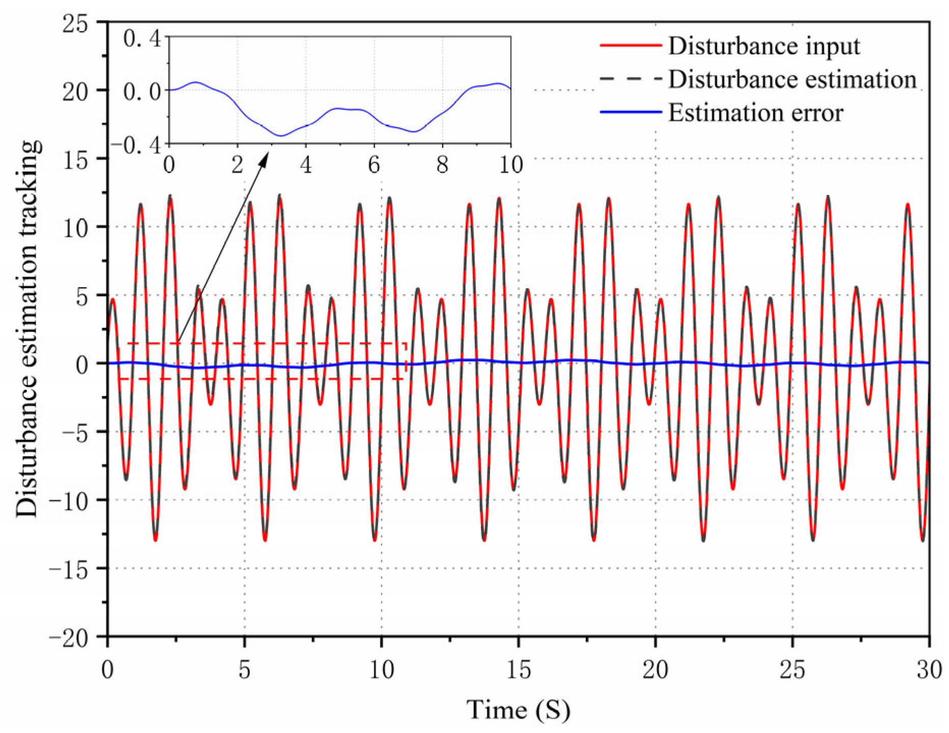
A finite time generalized extended state observer is designed for real-time monitoring of external disturbances, and the observed values are delivered to the controller to inhibit high gain feedback in the control system.
The structure of this paper is outlined as follows: The
Section 2 focuses on the independent metering control system of digital valves and establishes a hydraulic system model. The
Section 3 introduces the design of the sliding mode controller based on the RBF neural network and generalized extended state observer in accordance to the hydraulic system model of the digital valve. The
Section 4 mainly illustrates the establishment of the simulation model and provides a thorough analysis of the simulation results. The
Section 5 constructs an independent metering control system experimental platform with digital valves and compares the control performance of the experiment. The
Section 6 summarizes the key findings and contributions of this research.
2. Independent Metering Control System with Digital Valves
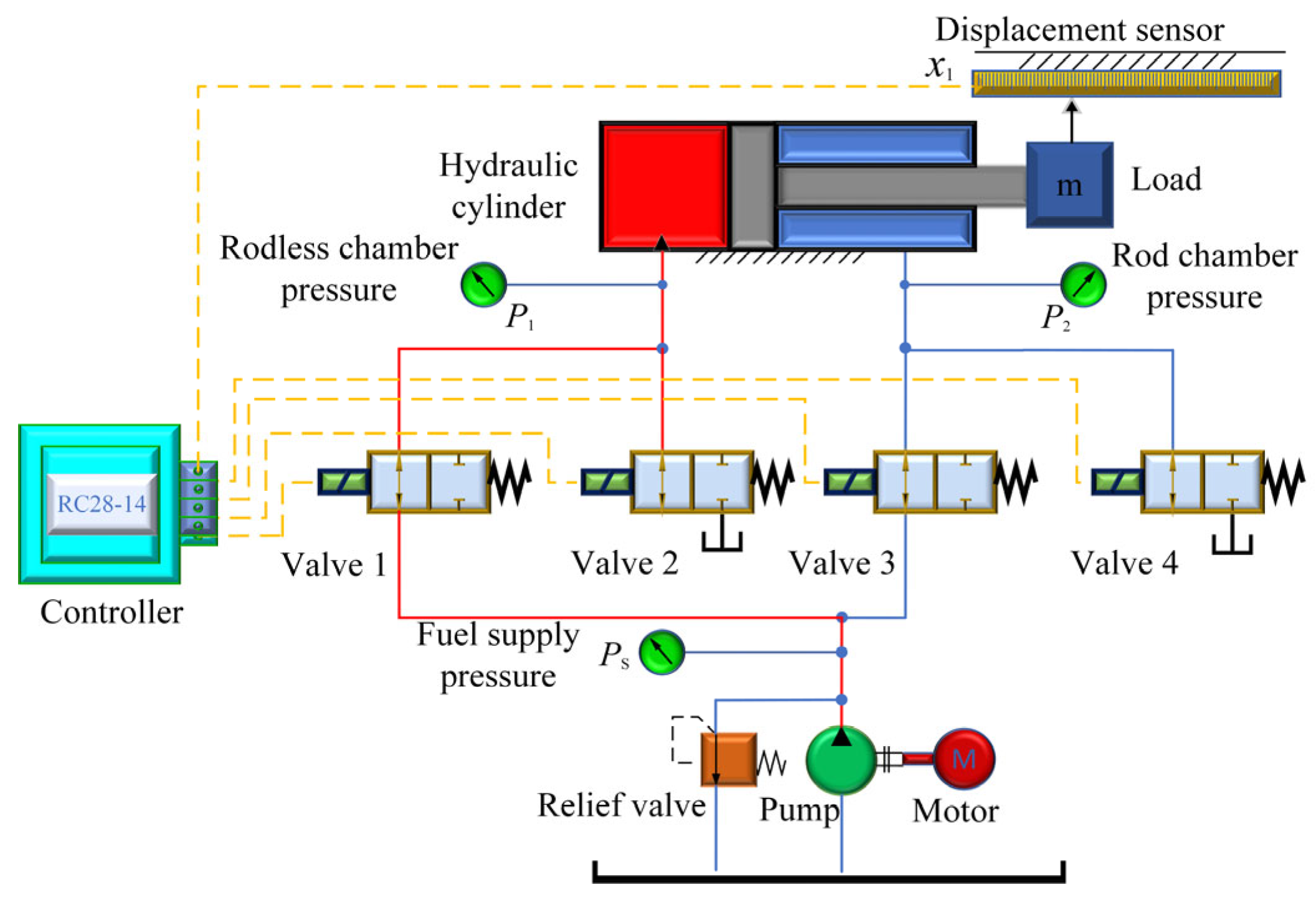
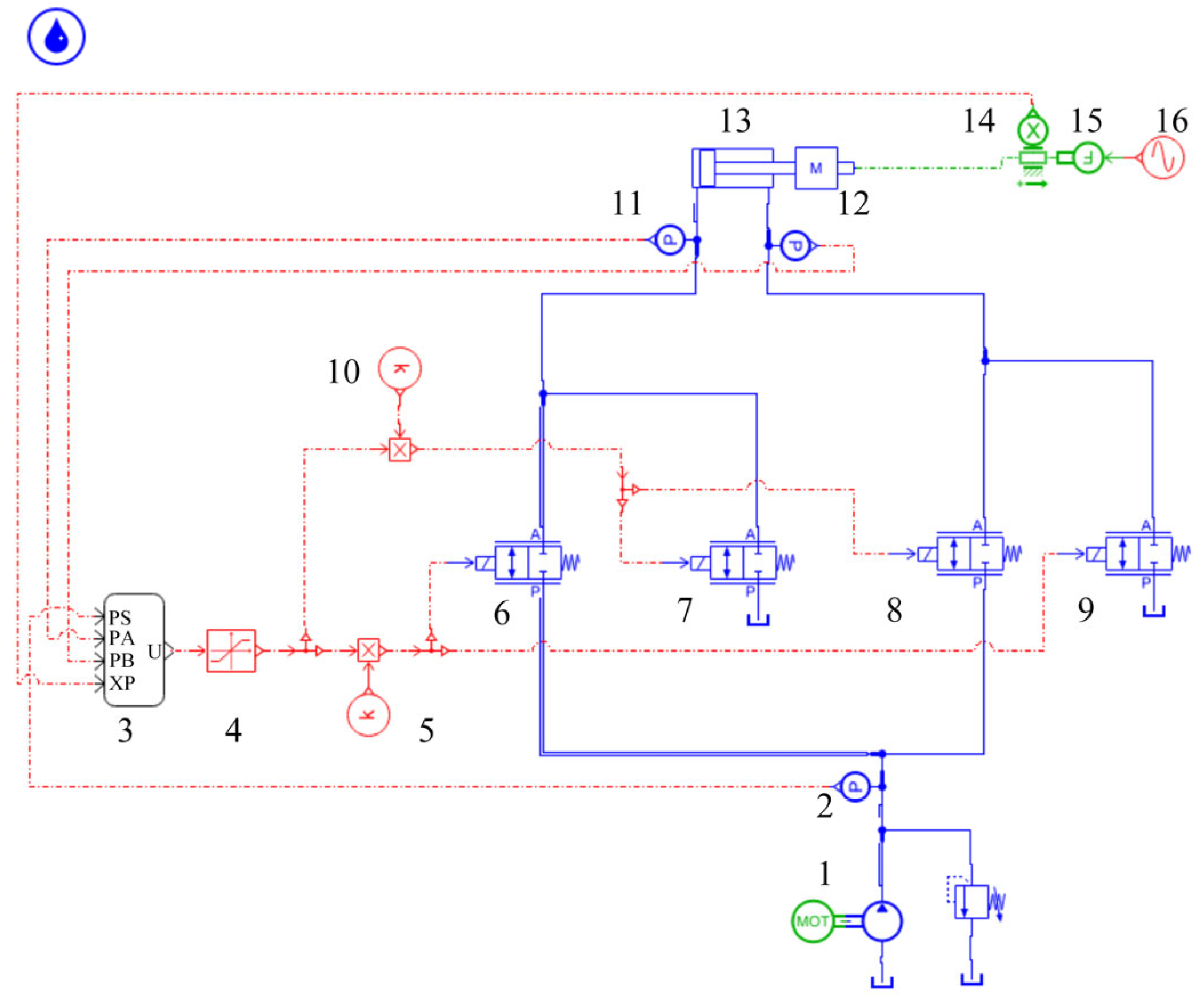
The position control principle for the digital valve-controlled hydraulic cylinder based on an independent metering control system is shown in
Figure 1. This includes motors, oil pumps, asymmetric hydraulic cylinders, displacement and pressure sensors, and controllers.
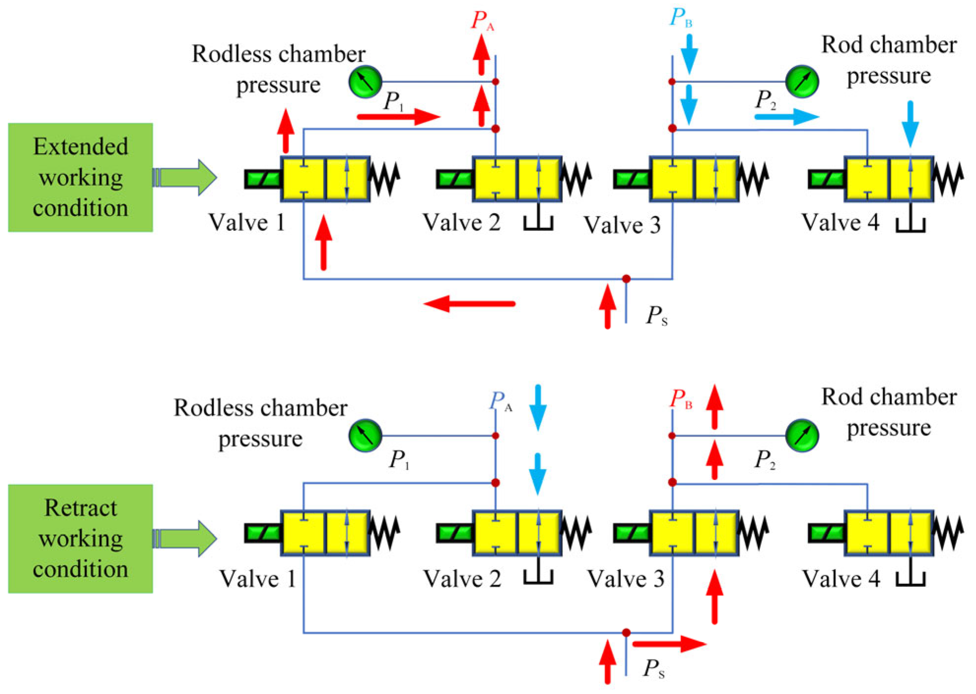
When the high-speed on-off valve 1 and 4 work at the same time, the high-pressure oil will enter from the rodless chamber of the asymmetrical hydraulic cylinder and flow back to the tank through the high-speed on-off valve 4. When the high-speed on-off valves 2 and 3 work at the same time, the high-pressure oil will enter from the rod chamber of the asymmetric hydraulic cylinder and flow back to the tank through the high-speed on-off valve 2. At the same time, the rod chamber pressure gauge will detect the working pressure and play a role in detecting pressure fluctuation. Only two solenoid valves can be powered simultaneously under any operating conditions, as shown in
Figure 2.
The process of establishing a mathematical model for the above hydraulic system is as follows:
It is assumed that is a constant-pressure source supplying oil to the system at a pressure of .
Hydraulic cylinders do not consider motion resistance and friction during their movement.
It is assumed that the hydraulic oil is incompressible.
The analysis object of the hydraulic system is an asymmetric hydraulic cylinder, and the effective area ratio of the two cavities of the hydraulic cylinder is assumed to be .
The flow rate through the valve port can be expressed by the following formula:
where
is the hydraulic cylinder rodless cavity area;
is the hydraulic cylinder rod cavity area;
is the oil inlet flow;
is the oil outlet flow;
is the digital valve flow coefficient;
is the digital valve flow area;
is the oil supply pressure;
is the oil return pressure;
is the controller signal output;
is the hydraulic cylinder rodless cavity pressure;
is the rod cavity pressure;
is the hydraulic oil density.
For asymmetric hydraulic cylinders, the load force expression is
, the load pressure expression is
, and the pressure difference between the two chambers is
. By putting the expression into Formula (1), the relation expression of hydraulic cylinder pressure
and
is obtained as follows:
where
represents the load pressure.
The output load force of the hydraulic cylinder is expressed as
.
is expressed as the equivalent area corresponding to the load pressure, and the equivalent area is obtained by combining this formula with (3).
Ignoring the influence of the length and diameter of the oil pipeline on the modeling, and ignoring the pressure loss of the fluid in the pipeline along the way, because the internal and external leakage are laminar flow, the flow continuity equation of the hydraulic system can be obtained as follows:
where
is the output displacement of the hydraulic cylinder. When the hydraulic cylinder piston rod is fully retracted,
.
is the leakage coefficient of the hydraulic cylinder;
is the leakage coefficient outside the hydraulic cylinder;
is the rodless chamber volume of the hydraulic cylinder;
is the hydraulic cylinder’s rod-free cavity area volume;
is the volume modulus of elasticity;
is the hydraulic cylinder rodless cavity area;
is the hydraulic cylinder rod cavity area.
In the hydraulic system, it is assumed that the initial volumes of the rod cavity and the rodless cavity of the hydraulic cylinder are
and
, respectively. Thus, the volume change formula of the two cavities of the hydraulic cylinder are
and
, and the total volume of the hydraulic cylinder is expressed as
. Thus, the relationship between the total volume and the initial volume is as follows:
The flow continuity equation of the hydraulic cylinder is expressed as
. Simultaneously, (5) obtains the following expression:
If the external leakage of the hydraulic cylinder is ignored, it is assumed that the flow transformation between the rodless cavity and the roded cavity of the hydraulic cylinder can be expressed in the following formula:
The derivation of Formula (3) to time
(assuming that the oil supply pressure
is constant) is:
Since the value of
is far less than the value of
, and
is far less than
, it can be ignored, simplifying the system modeling of the hydraulic cylinders. Thus, Formulas (8) and (9) become:
The derivation result of Equation (10) can be brought into (6) to obtain:
Thus, Equations (9) and (11) can be brought into (7) and simplified to get the following expression:
The fifth term in the expression can be ignored, so the expression is
:
where
is the equivalent area of the piston.
The balance equation of the output force and external load of the hydraulic cylinder is described as:
Therefore, the expression of the balance equation is:
Let the state variable of the system be
,,, and use Formulas (1)–(12) to establish the state balance equation of the hydraulic cylinder as follows:
In the above formula,
,
. Assuming there is external interference from
in the system,
is defined as follows:
In the above formula, is the hydraulic oil density; is the effective area ratio of the two chambers of the hydraulic cylinder; is the volume modulus of elasticity; is the hydraulic cylinder rod cavity area; is the digital valve flow coefficient; is the digital valve flow area.
5. Experimental Research
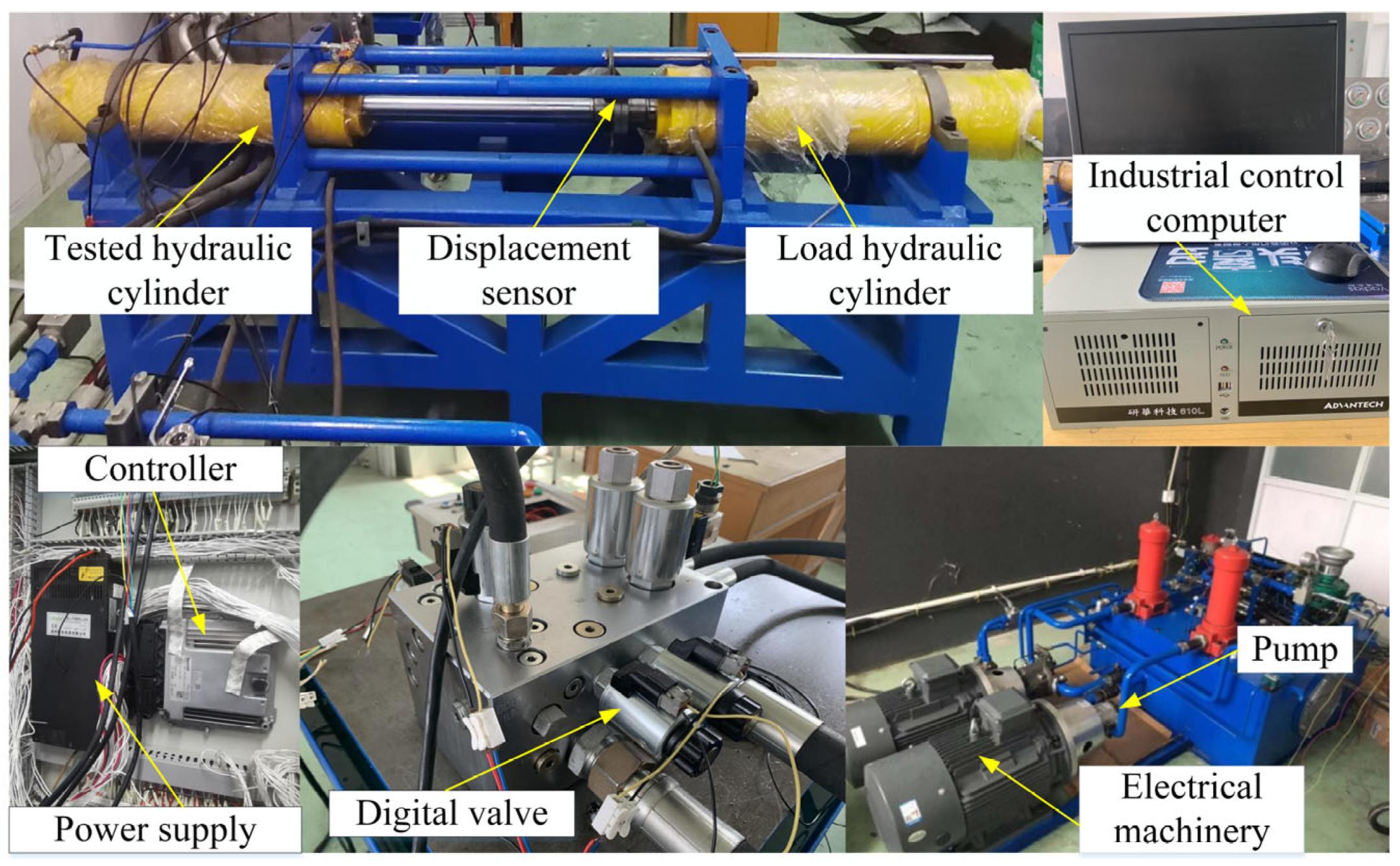
In order to further assess the effectiveness and applicability of the proposed control strategy, comparative experiments were carried out on a digital valve-controlled hydraulic cylinder test bench.
Figure 14 illustrates the experimental platform, which was comprised mainly of a hydraulic system consisting of a position test system and a load simulation system. The digital valve in the position test system was WS22GD, whose control voltage signal was 12 V. The maximum stroke of the piston rod was 0.6 m, and the displacement of the piston rod was measured by the drawstring displacement transducer MPS-S-650 mm-MA from Shenzhen Miran Technology Co., Ltd. in Shenzhen, China, whose stroke was in the range of 0–0.35 m. The output signal was 4–20 mA, and the proportional relief valve was DBE10-30B/200YM. The motor was Y160L-4-B35, and the variable pump was HA10Vs045DFLR/31R-PPA12N00. The industrial computer was the standard industrial computer of Advantech Technology, and the motion controller was the RC28-14 from Rexroth.
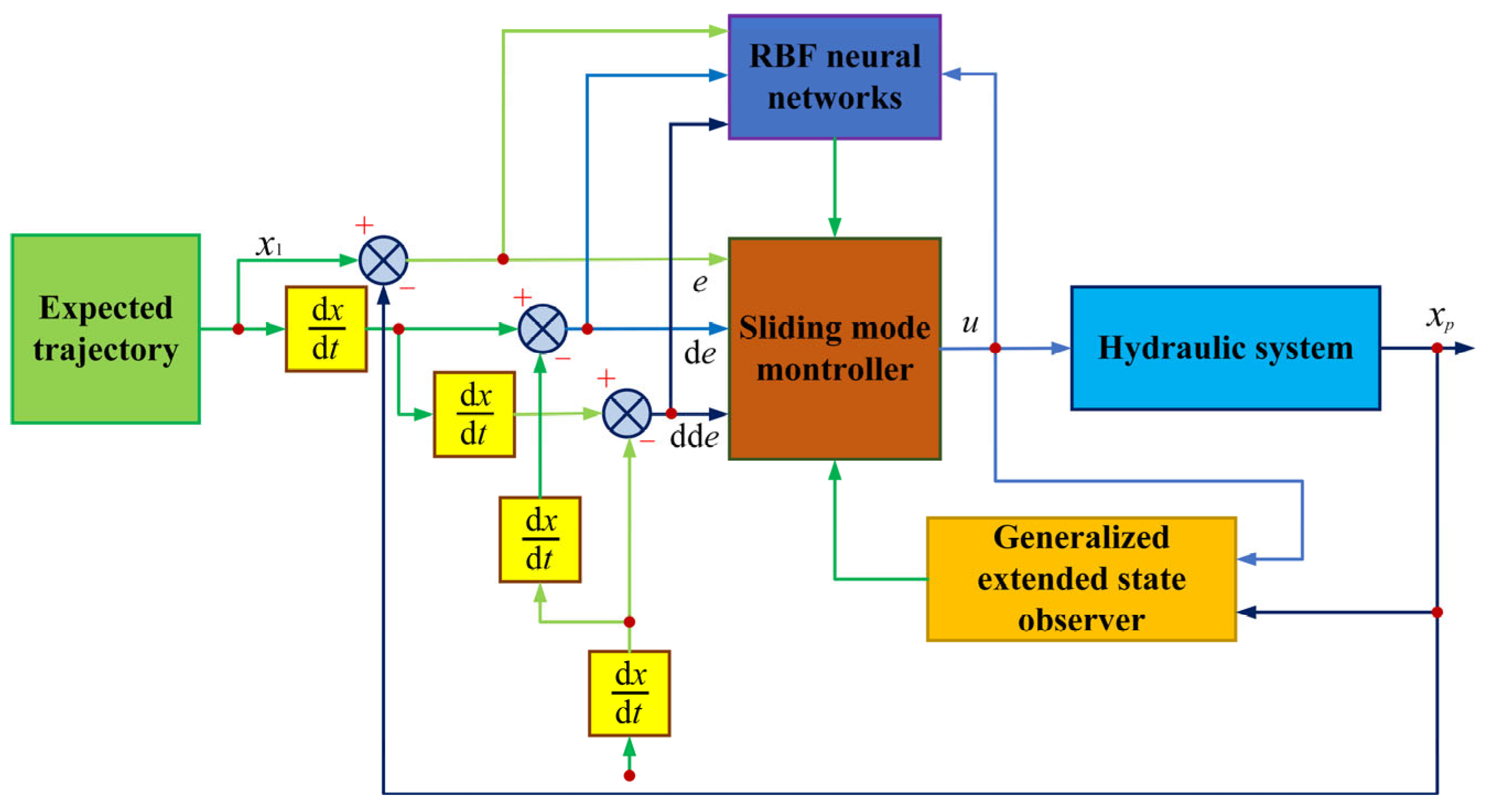
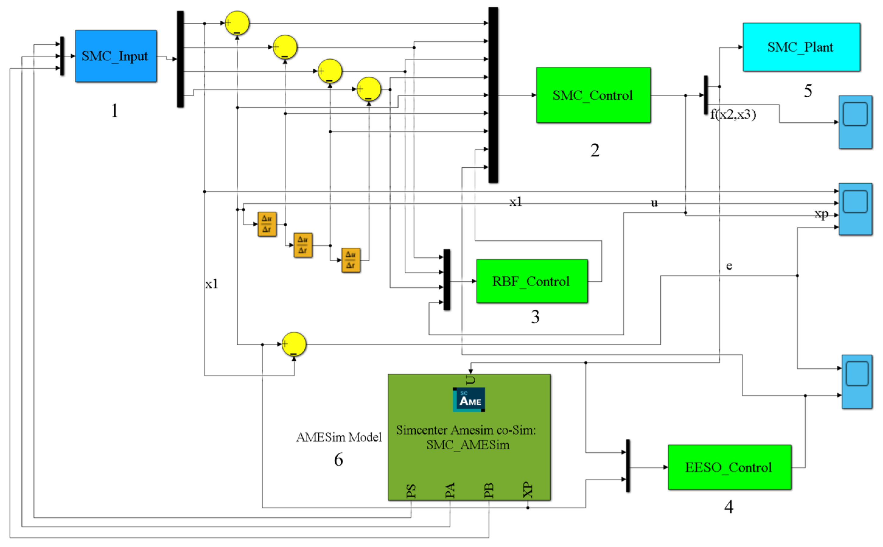
In this paper, the motion controller RC28-14 was utilized as the lower-level computer, and the industrial computer installed with MATLAB served as the upper-level computer. The control algorithm is depicted in
Figure 3. Communication between Simulink and the RC28-14 controller was achieved through PeakCAN, with the communication mode being CAN communication. Simulink was used to send high-speed switching digital valve CAN messages to the RC28-14 controller to control the valve’s operation. The RC28-14 controller, in turn, emitted sensor CAN messages to Simulink to provide the necessary parameters for the control algorithm. The control sampling period lasted for 2 ms, enabling closed-loop tracking control of the actual loading displacement and the target loading displacement of the load hydraulic cylinder.
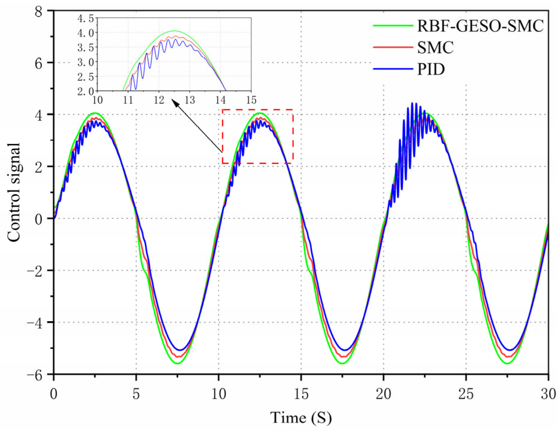
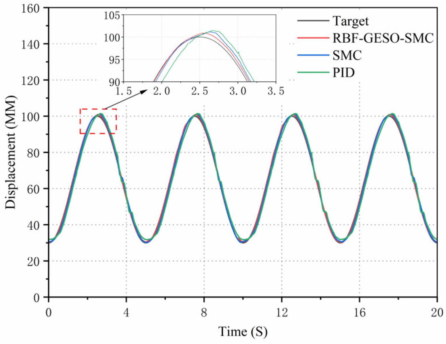
To ascertain the control effect of the RBF-GESO-SMC controller on the load hydraulic cylinder, two experiments were implemented to validate the software simulation results presented earlier. The control strategy proposed in this paper was compared with a traditional PID controller whose parameters were optimized using the Z-N method and an unoptimized SMC controller for verification purposes. The first experiment adopted a sinusoidal signal with an amplitude of 100 mm and a frequency of 0.2 Hz as the target signal, thereby verifying the tracking performance of the three control strategies for the target signal. The second experiment employed a ramp signal with a period of 20 s, a lower limit of 50 mm, and an upper limit of 120 mm as the target signal to verify the tracking performance and transient response characteristics of the three control strategies for the target signal.
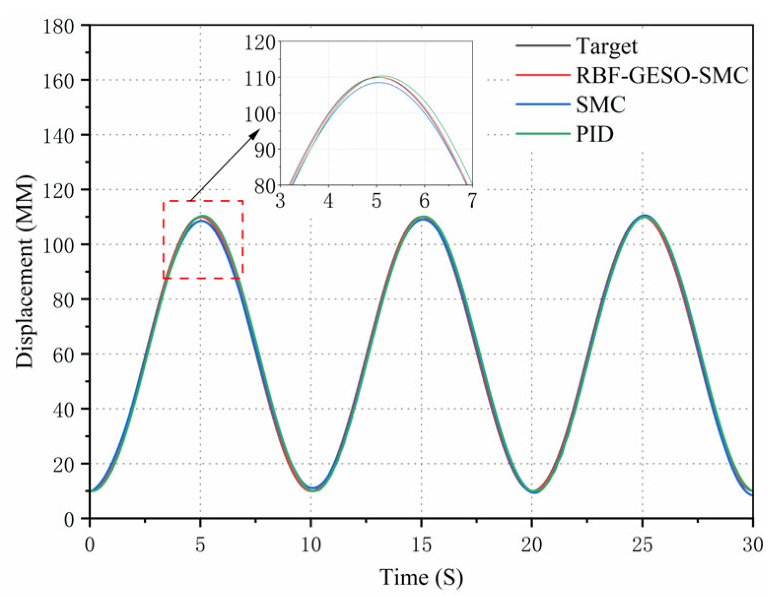
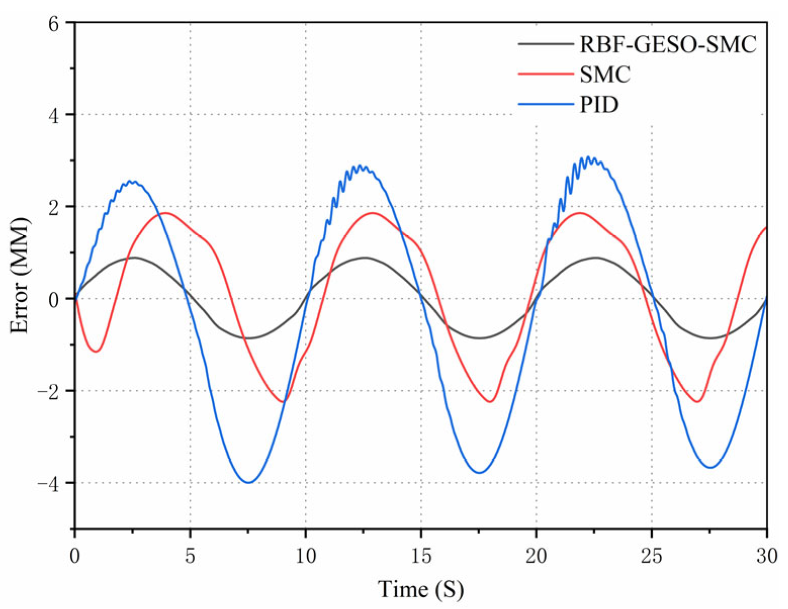
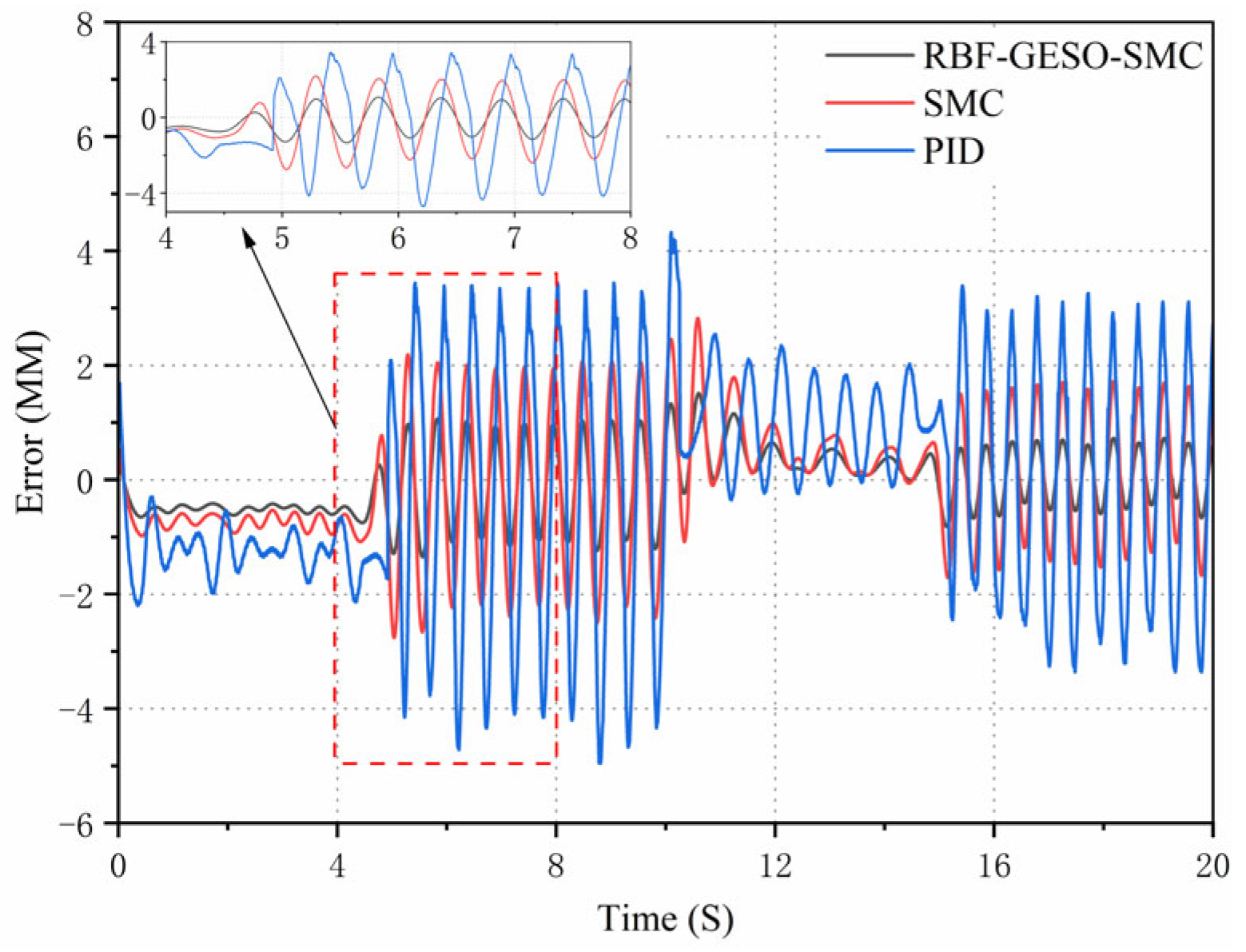
Firstly, to verify the displacement tracking performance of the RBF-GESO-SMC controller, the target signal was configured as a sinusoidal signal with an amplitude of 100 mm and a frequency of 0.2 HZ. The displacement response curves and error curves of the hydraulic cylinders under the three types of control are shown in
Figure 15 and
Figure 16.
As evident from the curves in
Figure 15 and
Figure 16, the tracking curve of the RBF-GESO-SMC controller closely aligned with the target curve, and the error amplitude of the peak-valley values was relatively small. Under the RBF-GESO-SMC controller, the maximum displacement tracking error was confined to be approximately 1.05 mm, with no discernible lead or lag in response. For the SMC controller, the maximum displacement tracking error was approximately 2.89 mm, and the lag phenomenon was quite obvious. Under the traditional PID controller, the maximum displacement tracking error was approximately 4.79 mm, accompanied by a conspicuous lag phenomenon. Compared with the SMC controller, the maximum displacement tracking error of the RBF-GESO-SMC controller was reduced by approximately 63.7%. Compared with the traditional PID controller, the maximum displacement tracking error of the RBF-GESO-SMC controller was diminished by approximately 78.1%. From the above analysis, it can be concluded that the RBF-GESO-SMC controller exhibited better performance in adapting to parameter uncertainties and nonlinear external disturbances. This enhanced the controller’s capabilities, effectively suppressing external disturbances.
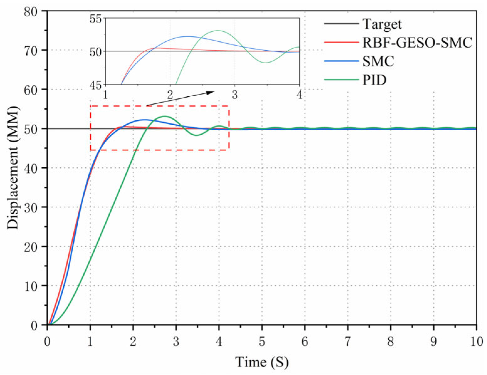
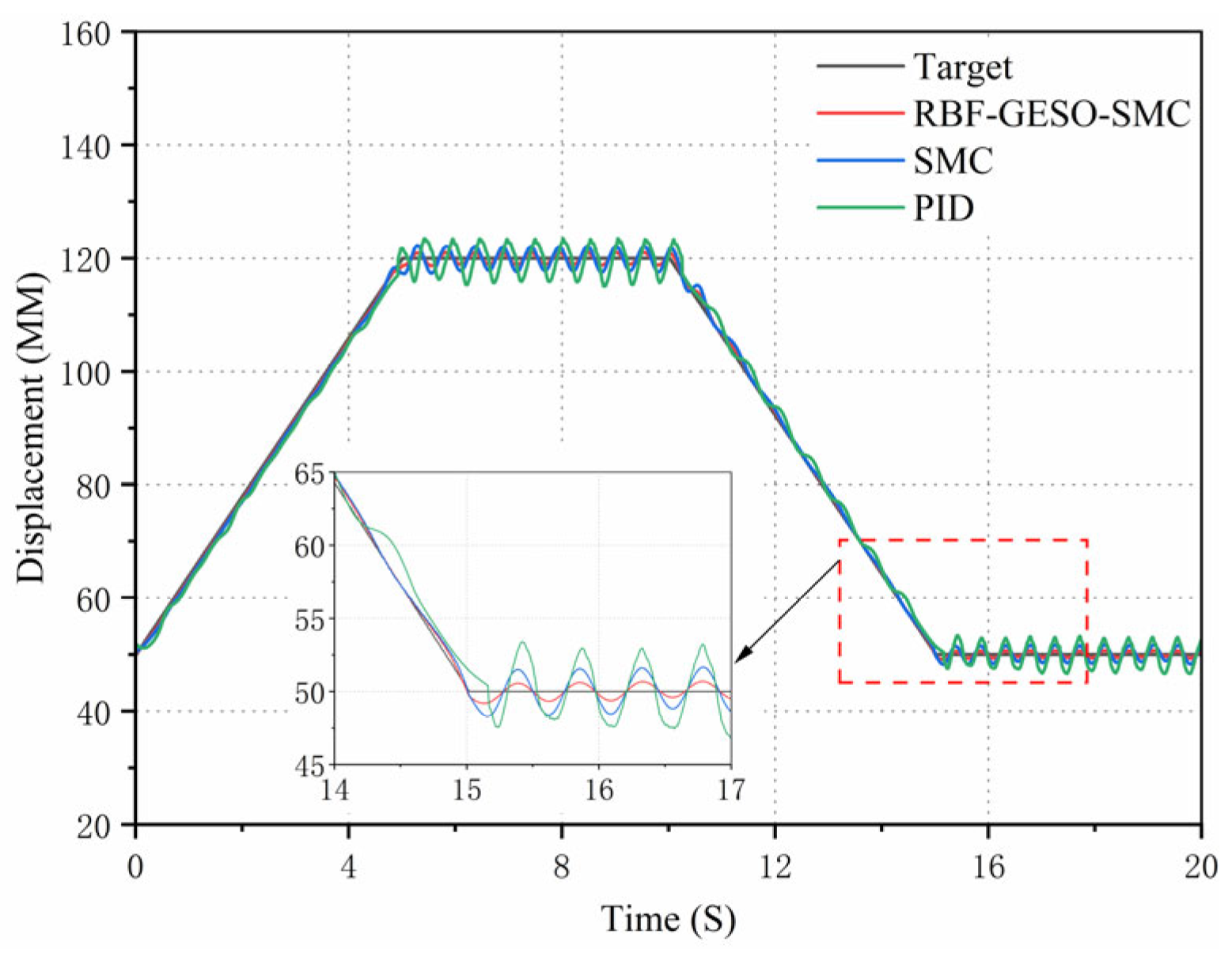
Finally, to validate the tracking performance of the RBF-GESO-SMC controller under external disturbances, a ramp signal with a period of 20 s and an amplitude ranging from 50 mm to 120 mm was employed as the target signal. The displacement response curves and error curves of the hydraulic cylinders under the three types of control are depicted in
Figure 17 and
Figure 18.
As can be seen from the curves in
Figure 17 and
Figure 18, the tracking curve of the RBF-GESO-SMC controller exhibited minimal susceptibility to external disturbances. Under the RBF-GESO-SMC controller, the disturbance tracking error was confined within 1.51 mm, and the response was rapid. For the SMC controller, the disturbance tracking error was 2.82 mm, and the response was relatively slow. Under the traditional PID controller, the disturbance tracking error was 4.95 mm, with a significantly lagged response. According to the experimental analysis, it can be inferred that the RBF-GESO-SMC controller possessed superior dynamic characteristics. That is, the system’s robustness to combined disturbances was enhanced, allowing for rapid and precise signal tracking, thus fulfilling the predefined tracking control objectives of the system.
The control performance indicators of the PID controller, SMC controller, and RBF-GESO-SMC controller in the experiment are detailed in
Table 4.
By comparing the performance indicators of the three controllers in
Table 4, under the experimental sinusoidal signal, the RBF-GESO-SMC controller demonstrated notable performance enhancements, with the maximum tracking error, average tracking error, and standard deviation of the tracking error of the RBF-GESO-RBF controller reduced by 78.1%, 80.1%, and 79.7%, respectively, compared with the PID controller, and by 63.7%, 55.7%, and 63.2%, respectively, compared with the SMC controller. Similarly, under the experimental ramp signal, it can be found that the maximum tracking error, average tracking error, and standard deviation of the tracking error of the RBF-GESO-RBF controller were reduced by 69.5%, 70.9%, and 70.6%, respectively, compared with the PID controller, and by 46.5%, 48.9%, 51.6%, respectively, compared with the SMC controller. The findings reveal that the RBF-GESO-SMC controller outperformed the other two controllers in the output of the three target signals.
6. Conclusions
This article addresses issues such as jitter, unknown dead zone nonlinearity, and time variance in electro-hydraulic proportional systems in hydraulic cylinder position control. An independent metering control system with digital valves was employed to regulate the position control of the hydraulic cylinder within the hydraulic system, and a high-order sliding mode digital valve control strategy was incorporated based on an RBF neural network and generalized extended state observer. Among them, the introduction of the RBF neural network and generalized extended state observer aimed to mitigate the effects caused by uncertainty and external disturbances of digital valve control systems. The RBF neural network enabled the estimation and compensation for parameter uncertainty through online approximation of unknown matching parameters and correction of adaptive control laws. Additionally, the generalized extended state observer offered real-time observation of external disturbances and fed the observed values back to the controller for prompt disturbance compensation. Finally, the Lyapunov function was utilized to verify the stability of the proposed control strategy; however, practical implementation of this proposed technology may encounter some obstacles in actual engineering scenarios. Therefore, it is imperative to enhance the robustness of digital valve control models and adjustable models to navigate the uncertainty of actual systems and meet the rapid response requirements of practical engineering. Meanwhile, optimizing the parameter settings of the controlled system is crucial for minimizing computational complexity and enhancing real-time observation capabilities. Looking forward, these challenges are expected to be surmounted progressively, thereby promoting further advancement and broader application of related technologies.
Then, through MATLAB/Simulink simulation, under conditions of parameter uncertainties and unknown external disturbances within the system, the simulation results suggest that the proposed control strategy exhibited a higher expected trajectory tracking accuracy compared with the SMC controller and the traditional PID controller. Compared with the SMC controller, the response speed increased by 13.6%, and the displacement tracking control accuracy error decreased by 60.5%. In contrast to the traditional PID controller, the response speed increased by 34.5%, and the error in displacement tracking control accuracy was reduced by 78.0%. Based on the analysis of simulation data, the control strategy proposed in this paper outperformed both the SMC controller and the traditional PID controller in terms of tracking performance and transient response performance under different operating conditions. However, the simulation results were obtained by using theoretical values for many system parameters, which means they are somewhat idealistic. Therefore, it is still crucial to establish a digital valve-controlled hydraulic cylinder test bench for displacement loading testing to verify the practical feasibility of the control strategy proposed in this paper.
Finally, the control strategy proposed in this article was applied to the digital valve-controlled hydraulic cylinder system for displacement loading testing for experimental verification. The results of the step and sine experiments revealed that this control strategy significantly enhanced the tracking accuracy and anti-interference performance of the electro-hydraulic servo system. Compared with the SMC controller, the error in displacement tracking control accuracy was decreased by 63.7%. Compared with the traditional PID controller, the displacement tracking control accuracy error was decreased by 78.1%. According to the above experiment, this control method significantly improved the tracking accuracy and anti-interference robustness of the digital valve-controlled hydraulic cylinder system. Its tracking accuracy, transient response speed, and anti-interference ability can effectively meet the accuracy and transient response performance requirements in actual hydraulic cylinder operation.


