

High-Precision Transdermal Drug Delivery Device with Piezoelectric Mechanism

Abstract
1. Introduction
2. Methods
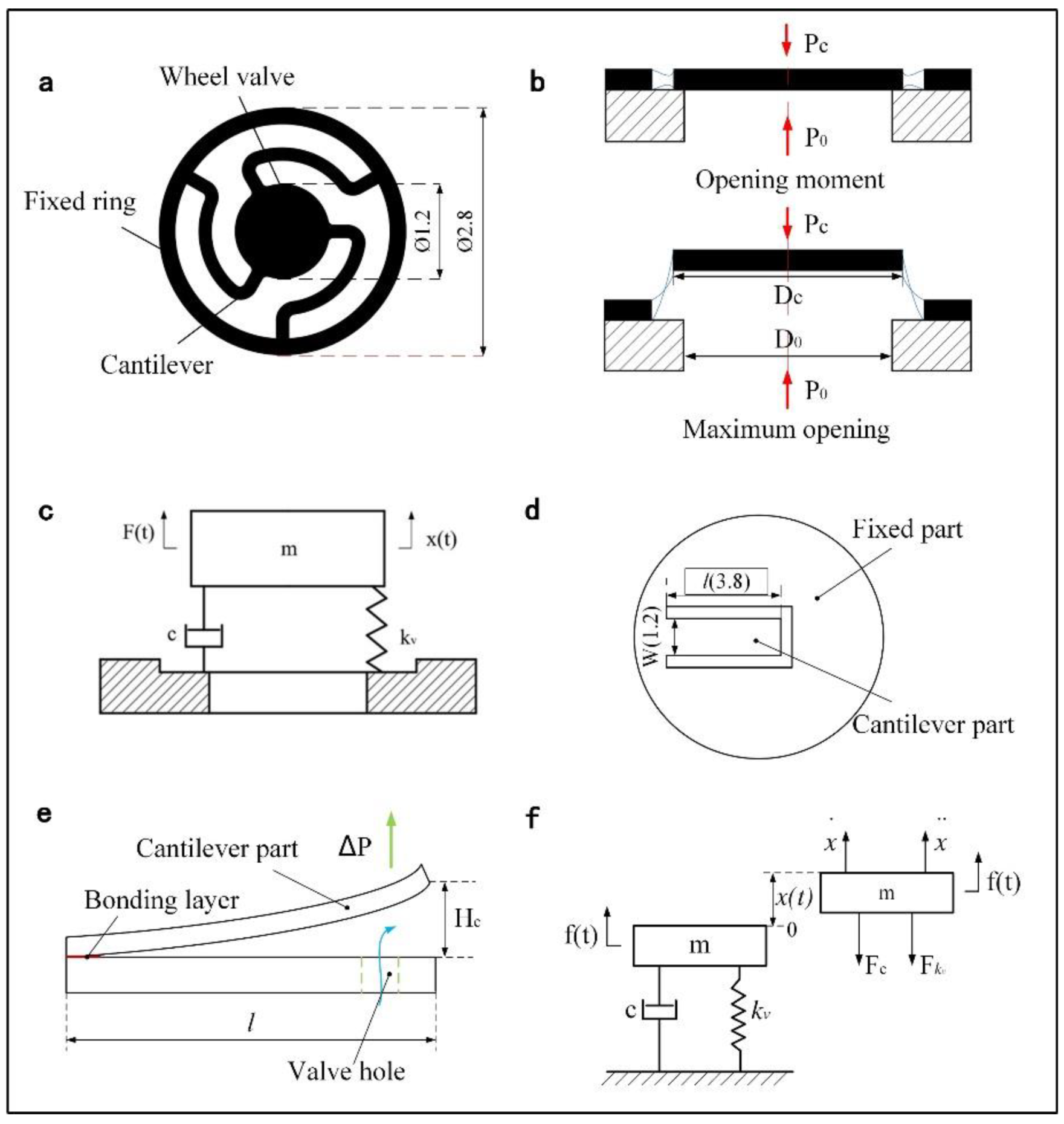
2.1. Overall Design
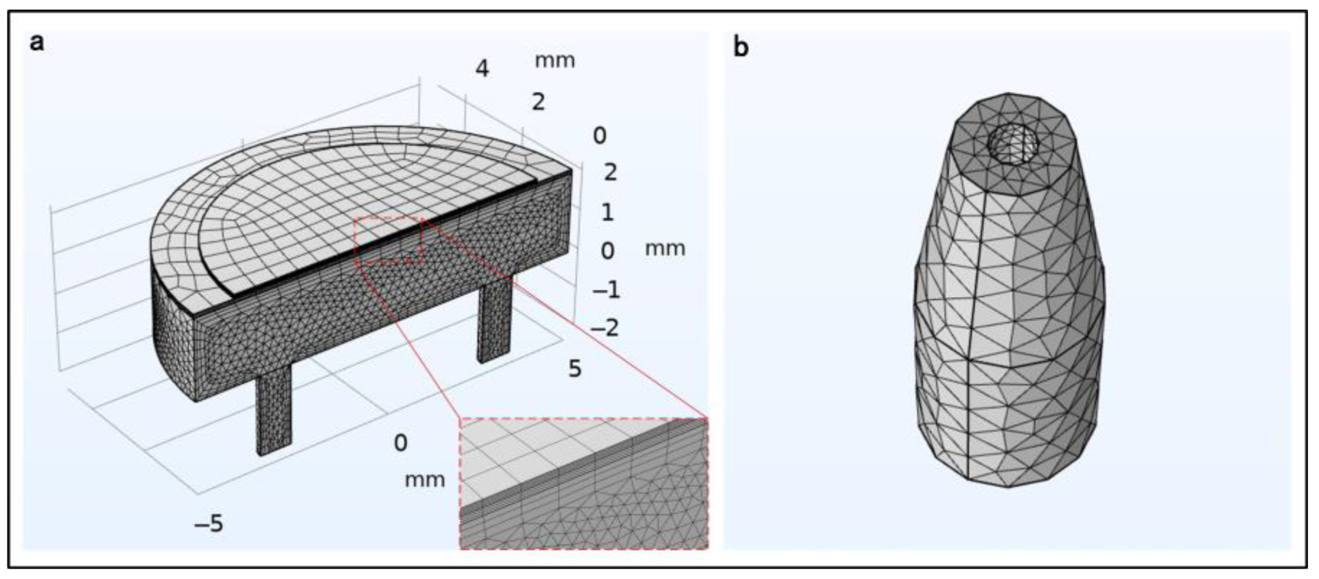
2.2. Numerical Simulation
2.3. Valve Characteristic
2.4. Experimental Setup
3. Results and Discussion
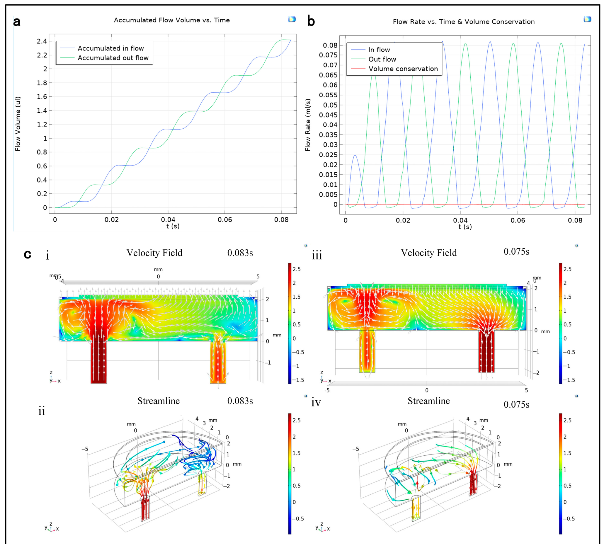
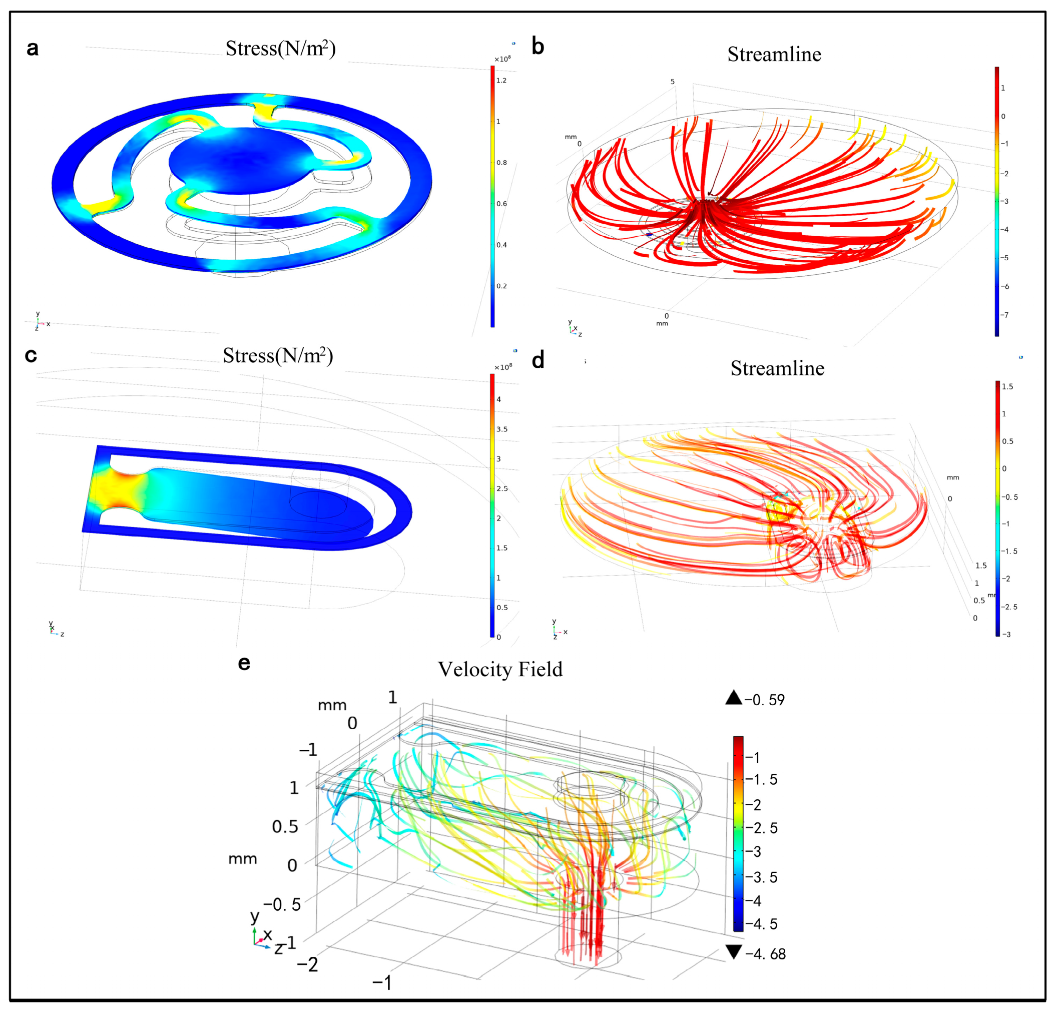
3.1. Simulation of the PE Micropump
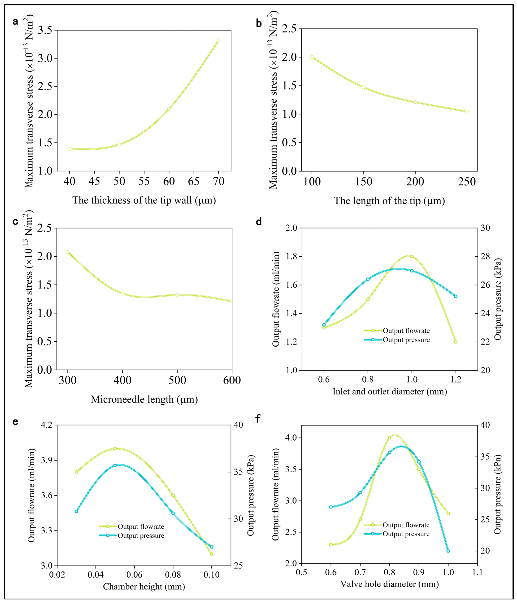
3.2. Simulation of the Microneedle
3.3. Optimization of Inlet and Outlet Diameters
3.4. Optimization of Chamber Height
3.5. Optimization of Valve Hole Diameter
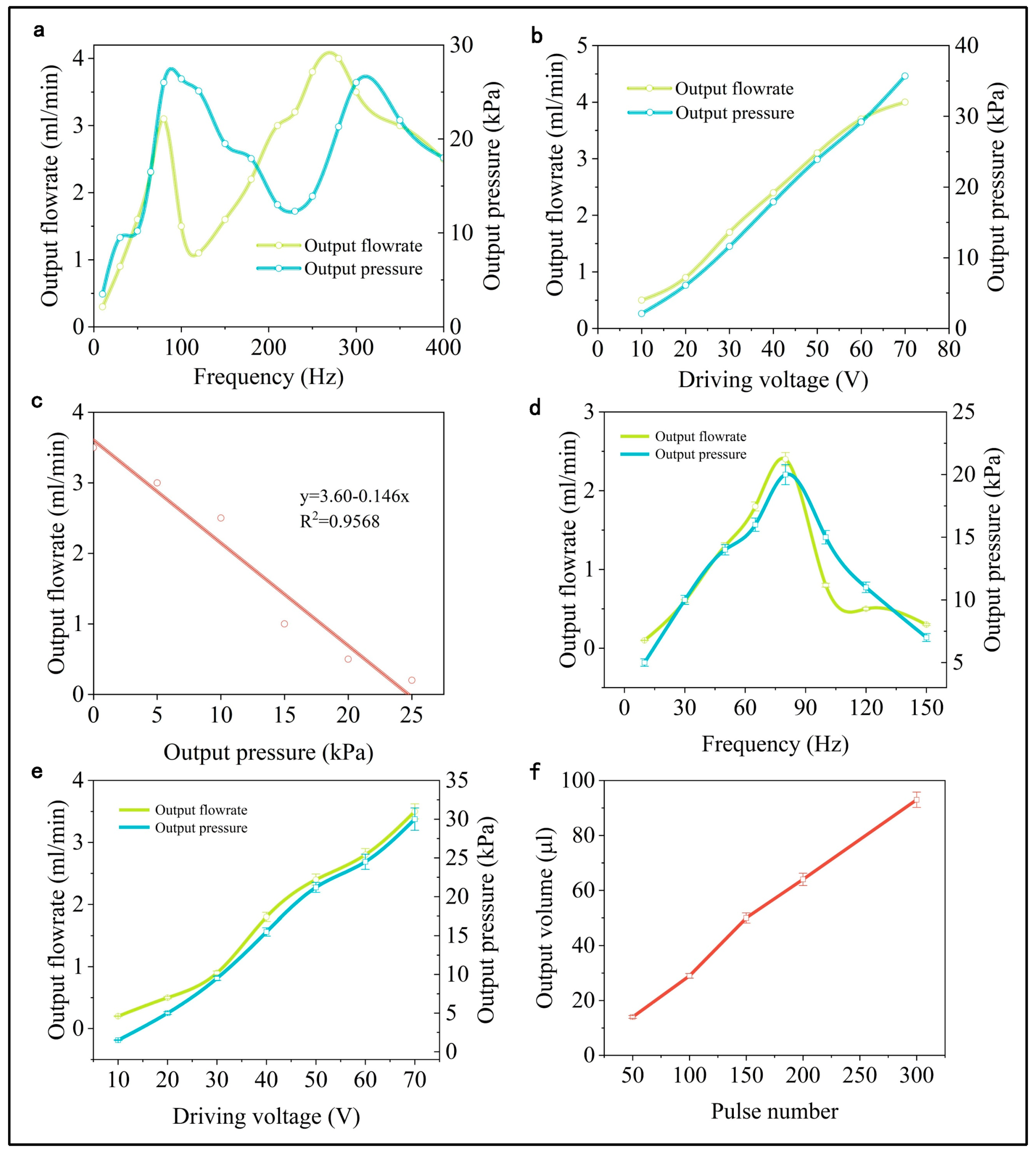
3.6. Output Performance Test
4. Conclusions
- The working principle of the PE micropump reveals that the fluid’s flow field within the chamber and channel changes due to the coordinated action of the PE vibrator and valve. This results in the fluid being pumped in and out in a staggered sequence, adhering to the principle of volume conservation.
- The chamber height can be fine-tuned to enhance self-priming capabilities without compromising the micropump’s output characteristics. The diameter ratio of the valve to the valve hole should be carefully selected to balance pressure loss, sealing efficacy, and assembly practicality. The inlet and outlet diameters must be optimized to minimize energy loss.
- The penetration of the microneedles into the skin is primarily driven by axial and lateral pressure. The mechanical characteristics of the microneedles are greatly influenced by factors such as tip wall thickness, tip length, and overall microneedle length.
- The output flow rate and pressure of the PE micropump initially increase and then decrease with rising operating frequencies. Conversely, at a constant operating frequency, both the flow rate and pressure show a positive correlation with the driving voltage, forming a nearly linear relationship. Under stable working conditions, the micropump’s output pressure is inversely related to its output flow, demonstrating a linear correlation.
- At an operating voltage of 70 V and a frequency of 80 Hz, the micropump achieves an output flow of 4.0 mL/min and a pressure of 35.7 kPa. The output flow rate and pressure of the device with the integrated microneedle array were 3.5 mL/min, 30 kPa, with a minimum flow resolution of 0.28 μL, demonstrating the effectiveness and practicality of the design.
Author Contributions
Funding
Data Availability Statement
Conflicts of Interest
References
- Lu, S.; Yu, M.; Qian, C.; Deng, F.; Zhang, Z. A Quintuple-Bimorph Tenfold-Chamber Piezoelectric Pump Used in Water-Cooling System of Electronic Chip. IEEE Access 2020, 8, 186691–186698. [Google Scholar] [CrossRef]
- Anh, P.N.; Bae, J.S.; Hwang, J.H. Computational Fluid Dynamic Analysis of Flow Rate Performance of a Small Piezoelectric-Hydraulic Pump. Appl. Sci. 2021, 11, 4888. [Google Scholar] [CrossRef]
- Woo, J.; Sohn, D.K.; Ko, H.S. Performance and flow analysis of small piezo pump—ScienceDirect. Sens. Actuators A Phys. 2020, 301, 111766. [Google Scholar] [CrossRef]
- Senjanović, I.; Vladimir, N.; Tomić, M. On new first-order shear deformation plate theories. Mech. Res. Commun. 2016, 73, 31–38. [Google Scholar] [CrossRef]
- Wu, X.; He, L.; Hou, Y.; Tian, X.; Zhao, X. Advances in passive check valve piezoelectric pumps. Sens. Actuators A Phys. 2021, 323, 112647. [Google Scholar] [CrossRef]
- Liu, G.; Wang, M.; Li, P.; Sun, X.; Dong, L.; Li, P. A micromixer driven by two valveless piezoelectric pumps with multi-stage mixing characteristics. Sens. Actuators A Phys. 2021, 333, 113225. [Google Scholar] [CrossRef]
- Wang, X.; Liu, Z.; Wang, B.; Cai, Y.; Song, Q. An overview on state-of-art of micromixer designs, characteristics and applications. Anal. Chim. Acta 2023, 1279, 341685. [Google Scholar] [CrossRef]
- Zhou, D.; Qin, L.; Yue, J.; Yang, A.; Jiang, Z.; Zheng, S. Numerical and experimental investigations of spiral and serpentine micromixers over a wide Reynolds number range. Int. J. Heat Mass Transf. 2023, 212, 124273. [Google Scholar] [CrossRef]
- Zhao, P.; Wang, H.; Wang, Y.; Zhao, W.; Han, M.; Zhang, H. A time sequential microfluid sensor with Tesla valve channels. Nano Res. 2023, 16, 11667–11673. [Google Scholar] [CrossRef]
- Wu, T.; Shen, J.; Li, Z.; Xing, F.; Xin, W.; Wang, Z.; Liu, G.; Han, X.; Man, Z.; Fu, S. Microfluidic-integrated graphene optical sensors for real-time and ultra-low flow velocity detection. Appl. Surf. Sci. 2021, 539, 148232. [Google Scholar] [CrossRef]
- Hu, R.; He, L.; Hu, D.; Hou, Y.; Cheng, G. Recent studies on the application of piezoelectric pump in different fields. Microsyst. Technol. 2023, 29, 663–682. [Google Scholar] [CrossRef]
- Jun, H.; Jianhui, Z.; Weidong, S.; Yuan, W. 3D FEM Analyses on Flow Field Characteristics of the Valveless Piezoelectric Pump. Chin. J. Mech. Eng. 2016, 29, 825–831. [Google Scholar]
- Zhao, D.; He, L.P.; Li, W.; Huang, Y.; Cheng, G.M. Experimental analysis of a valve-less piezoelectric micropump with crescent-shaped structure. J. Micromech. Microeng. 2019, 29, 105004. [Google Scholar] [CrossRef]
- Cheng, C.H.; Yang, A.S.; Lin, C.J.; Huang, W.J. Characteristic studies of a novel piezoelectric impedance micropump. Microsyst. Technol. 2017, 23, 1709–1717. [Google Scholar] [CrossRef]
- Yeming, S.; Junyao, W. Digitally-controlled driving power supply for dual-active-valve piezoelectric pump. Microsyst. Technol. 2019, 25, 1257–1265. [Google Scholar] [CrossRef]
- Sakuma, S.; Kasai, Y.; Hayakawa, T.; Arai, F. On-chip cell sorting by high-speed local-flow control using dual membrane pumps. Lab Chip 2017, 17, 2760–2767. [Google Scholar] [CrossRef]
- Haber, J.M.; Gascoyne, P.R.C.; Sokolov, K. Rapid real-time recirculating PCR using localized surface plasmon resonance (LSPR) and piezo-electric pumping. Lab Chip 2017, 17, 2821–2830. [Google Scholar] [CrossRef]
- Mohith, S.; Karanth, P.N.; Kulkarni, S.M. Recent trends in mechanical micropumps and their applications: A review. Mechatronics 2019, 60, 34–55. [Google Scholar] [CrossRef]
- Elahpour, N.; Pahlevanzadeh, F.; Kharaziha, M.; Bakhsheshi-Rad, H.R.; Ramakrishna, S.; Berto, F. 3D printed microneedles for transdermal drug delivery: A brief review of two decades. Int. J. Pharm. 2021, 597, 120301. [Google Scholar] [CrossRef]
- Cárcamo-Martínez, Á.; Mallon, B.; Domínguez-Robles, J.; Vora, L.K.; Anjani, Q.K.; Donnelly, R.F. Hollow microneedles: A perspective in biomedical applications. Int. J. Pharm. 2021, 599, 120455. [Google Scholar] [CrossRef]
- Ahmad, N.F.N.; Ghazali, N.N.N.; Wong, Y.H. Concept Design of Transdermal Microneedles for Diagnosis and Drug Delivery: A Review. Adv. Eng. Mater. 2021, 23, 2100503. [Google Scholar] [CrossRef]
- Rao, K.S.; Sateesh, J.; Guha, K.; Baishnab, K.L.; Ashok, P.; Sravani, K.G. Design and analysis of MEMS based piezoelectric micro pump integrated with micro needle. Microsyst. Technol. 2018, 26, 3153–3159. [Google Scholar] [CrossRef]
- Garcia, J.; Rios, I.; Fonthal Rico, F. Design and Analyses of a Transdermal Drug Delivery Device (TD(3)) dagger. Sensors 2019, 19, 5090. [Google Scholar] [CrossRef] [PubMed]
- Haldkar, R.K.; Khalatkar, A.; Gupta, V.K.; Sheorey, T. New piezoelectric actuator design for enhance the micropump flow. Mater. Today Proc. 2021, 44, 776–781. [Google Scholar] [CrossRef]
- Karumuri, S.R.; Mohammed, H.; Guha, K.; Puli, A.K.; Einsanwi, A.; Kondavitee, G.S. Design, simulation and analysis of micro electro-mechanical system microneedle for micropump in drug delivery systems. IET Nanobiotechnol. 2021, 15, 484–491. [Google Scholar] [CrossRef]
- Meshkinfam, F.; Rizvi, G. A MEMS Based Drug Delivery Device with Integrated Micro-Needle Array—Design and Simulation. J. Biomech. Eng. 2021, 143, 081010. [Google Scholar] [CrossRef]
- Dong, J.; Cao, Y.; Chen, Q.; Wu, Y.; Liu, R.G.; Liu, W.; Yang, Y.; Yang, Z. Performance of single piezoelectric vibrator micropump with check valve. J. Intell. Mater. Syst. Struct. 2019, 31, 117–126. [Google Scholar] [CrossRef]
- Wang, J.; Zhao, X.; Chen, X.; Yang, H. A Piezoelectric Resonance Pump Based on a Flexible Support. Micromachines 2019, 10, 169. [Google Scholar] [CrossRef]
- Cheng, C.H.; Tseng, Y.P. Characteristic studies of the piezoelectrically actuated micropump with check valve. Microsyst. Technol. 2013, 19, 1707–1715. [Google Scholar] [CrossRef]
- Liu, G.; Yang, Z.; Liu, J.; Li, X.; Wang, H.; Zhao, T.; Yang, X. A low cost, high performance insulin delivery system based on PZT actuation. Microsyst. Technol. 2014, 20, 2287–2294. [Google Scholar] [CrossRef]


| Type | Symbol | Value | Unit |
|---|---|---|---|
| Density | 7600 | kg/m3 | |
| PE constant | d31 | −275 | 10−12 C/N |
| d33 | 650 | ||
| PE voltage coefficient | g31 | −9 | 10−3 Vm/N |
| g33 | 19 | ||
| Mechanical quality factor | Qm | 50 | / |
Disclaimer/Publisher’s Note: The statements, opinions and data contained in all publications are solely those of the individual author(s) and contributor(s) and not of MDPI and/or the editor(s). MDPI and/or the editor(s) disclaim responsibility for any injury to people or property resulting from any ideas, methods, instructions or products referred to in the content. |
© 2025 by the authors. Licensee MDPI, Basel, Switzerland. This article is an open access article distributed under the terms and conditions of the Creative Commons Attribution (CC BY) license (https://creativecommons.org/licenses/by/4.0/).
Share and Cite
Liu, S.; Liu, J.; Wang, C.; Zhan, Y. High-Precision Transdermal Drug Delivery Device with Piezoelectric Mechanism. Actuators 2025, 14, 212. https://doi.org/10.3390/act14050212
Liu S, Liu J, Wang C, Zhan Y. High-Precision Transdermal Drug Delivery Device with Piezoelectric Mechanism. Actuators. 2025; 14(5):212. https://doi.org/10.3390/act14050212
Chicago/Turabian StyleLiu, Shengyu, Junming Liu, Conghui Wang, and Yang Zhan. 2025. "High-Precision Transdermal Drug Delivery Device with Piezoelectric Mechanism" Actuators 14, no. 5: 212. https://doi.org/10.3390/act14050212
APA StyleLiu, S., Liu, J., Wang, C., & Zhan, Y. (2025). High-Precision Transdermal Drug Delivery Device with Piezoelectric Mechanism. Actuators, 14(5), 212. https://doi.org/10.3390/act14050212