Article

Reliability Modeling and Verification of Locking Mechanisms Based on Failure Mechanisms

1
Zhejiang Key Laboratory of Reliability Technology for Mechanical & Electrical Product, Zhejiang Sci-Tech University, Hangzhou 310018, China
2
College of Engineering, Huzhou University, Huzhou 313000, China
*
Author to whom correspondence should be addressed.
Actuators 2025, 14(5), 205; https://doi.org/10.3390/act14050205
Submission received: 16 March 2025 / Revised: 11 April 2025 / Accepted: 14 April 2025 / Published: 23 April 2025

Abstract

:
The locking mechanism is crucial for the reliable connection and disconnection of electrical connectors. Aiming at the lack of theoretical support for the reliability evaluation in long-term storage, a comprehensive multi-theory modeling method is proposed to solve unlocking failure and related performance-evaluation problems. An analysis reveals that metal-crystal dislocation glide, causing pull-rod deformation and spring stress relaxation, is the main cause of unlocking failure. Based on Hertz’s contact theory, a locking-state mechanical model is established. Integrating the crystal dislocation-slip theory, an accelerated degradation trajectory model considering design parameters is developed to characterize the friction between the pull rod and steel ball and the spring’s elastic-force degradation. Finally, the model is verified using the unlocking-force accelerated test data. It offers a theoretical basis for the reliability evaluation and design of locking mechanisms in long-term storage environments.

1. Introduction

The separation electrical connector is a critical component widely used in inter-stage electrical systems to achieve signal separation between stages. Failure of the locking mechanism to unlock can lead to system failure, resulting in severe consequences. Despite the importance of the locking mechanism in ensuring the reliable separation of electrical connectors, limited research has been conducted on its performance following prolonged storage. Extended storage can compromise the unlocking reliability of the mechanism. Therefore, we developed an accelerated degradation model using a specific type of center pull-rod locking mechanism as a case study to evaluate its performance under storage conditions.
Researchers worldwide have investigated the performance degradation of separable electrical connectors in storage environments. Most studies have focused on critical aspects such as contact, insulation, and sealing performance. Lei et al. [1,2,3,4] explored the impact of various conditions on electrical contact failure using a comprehensive approach in electrical connectors. Qin et al. [5,6,7,8] clarified the relationship between design factors and contact resistance in electrical connectors, providing valuable theoretical guidance for studying electromechanical characteristics and designing related experiments. He et al. [9] developed a wear simulation method incorporating thermal, electrical, and mechanical factors to investigate the evolution of contact variables and resistance. Shukla et al. [10] introduced a data-driven approach to estimate electrical connectors’ lifespan and failure-in-time (FIT) rate based on contact resistance data from short-term tests. Siddaiah et al. [11] conducted a tribological analysis of degradation mechanisms in internal components of electrical connectors, concluding that friction and wear are primary factors contributing to degradation. They quantified contact resistance and friction coefficients through experimental measurements. Wang et al. [12,13] developed a reliability model for silicone-rubber insulating components and assessed their storage reliability lifetime through testing. Jiang [14,15] examined the effects of temperature and insulation materials on the insulation resistance of electrical connectors and the influence of environmental temperature on the dielectric properties of insulating materials. Chen [16] studied the performance evolution of 771 silicone rubber seals and assessed their reliable service life under storage conditions. Angadi et al. [17] reviewed a finite-element analysis (FEM) of electrical connectors conducted by researchers worldwide in key contact regions, concluding that FEM is essential for enhancing connector design. Hilmert et al. [18] analyzed failure mechanisms in electrical connectors by comparing faulty units to similar models, offering valuable insights into the root causes of failures. Kruger et al. [19,20] developed an accelerated model for predicting the reliability of electrical connectors, providing guidelines for selecting optimal upper-temperature limits and test durations, creating a robust framework for evaluating longevity.
Currently, research on mechanism reliability primarily focuses on mechanical products’ motion and precision reliability. Liu et al. [21,22] established a tolerance optimization design model based on mechanism motion reliability, incorporating considerations such as dimensional tolerance, motion reliability under mixed uncertainty, manufacturing cost, and quality loss. Feng [23,24] conducted a comprehensive analysis of mechanism motion reliability during the start-up and continuous-operation stages, derived the margin equation for wear reliability, and established a systematic reliability assessment method. Xue et al. [25] derived the error model for the position and posture of the folding-arm mechanism using the differential method. They applied the First-Order Second-Moment Method (FOSM) to analyze the motion reliability of the mechanism under various uncertain factors. Li et al. [26] investigated the impact of kinematic errors on robot motion accuracy and analyzed mechanisms’ motion reliability. Yao [27] examined the effects of corrosion and wear on kinematic reliability, proposing a time-varying reliability analysis method for uncertain kinematic systems involving random variables and stochastic processes. Chen and Gao [28,29] introduced methods to model and evaluate the kinematic accuracy reliability of complex multi-link mechanisms. Yang et al. [30] conducted an in-depth analysis of parallel mechanisms, assessing the effects of errors and joint clearances on the position accuracy of the end effector in real-world working environments. Lv et al. [31,32,33] carried out in-depth research on the performance degradation issues of wireless sensor networks, transformers, and proton-exchange membrane fuel cells. A fault-diagnosis framework was meticulously constructed, and a performance degradation function was established to enhance the accuracy of performance prediction effectively. Subsequently, a comprehensive analysis was performed on the stability and performance of the derived fault-detection system. Finally, the rationality of the system was validated by means of simulation.
Several scholars have also researched the performance evaluation of locking mechanisms in their original factory state and conducted structural optimization studies. Chang et al. [34] comprehensively analyzed connectors’ domestic and international locking and unlocking mechanisms, systematically summarizing the technical characteristics of existing connector locking and unlocking schemes. Yang and Chen et al. [35,36] addressed the unlocking reliability of the steel-ball locking mechanism in separable electrical connectors, and developed dynamic and separation reliability models for the locking mechanism, assessing its reliability based on size parameters. Mealier et al. [37] assessed the reliability of the locking system using the complementary failure probability approach, utilizing FORM and SORM as approximate methods and Monte Carlo simulation as a reference method, aided by the reliability analysis software Phimeca. Tan et al. [38] developed a novel analytical model to assess the functional reliability of spatial cable-strut structures, incorporating specific locking events and data from deployable masts to enhance reliability calculations. Hao [39] conducted a comprehensive analysis of the force conditions experienced by the retaining ring, a critical component of the locking mechanism, and performed reliability assessments and optimization designs for the retaining ring structure, significantly enhancing the operational reliability of the separable electrical connector. Zhuang [40,41,42] proposed a novel locking structure for the docking mechanism that satisfies the requirements of large-tolerance jointing and validated the structural integrity of the locking mechanism. Chen [43] analyzed the service life of ball joints in mechanisms, developing a wear life model and evaluation method based on precision requirements. Huang et al. [44] designed an electromagnetic trigger-based locking and release mechanism, successfully developed an engineering prototype, and conducted comprehensive performance evaluations to validate its functionality.
Figure 1 illustrates the research concept of this article. This paper takes a certain type of central pull-rod locking mechanism as the research object. Based on the failure mechanism analysis and mechanical analysis of key components, an unlocking performance degradation model and a reliability model of the central pull-rod locking mechanism are established. By carrying out accelerated degradation tests and conducting statistical analysis of the test data, the parameter estimation and model verification of the mechanism model are completed.

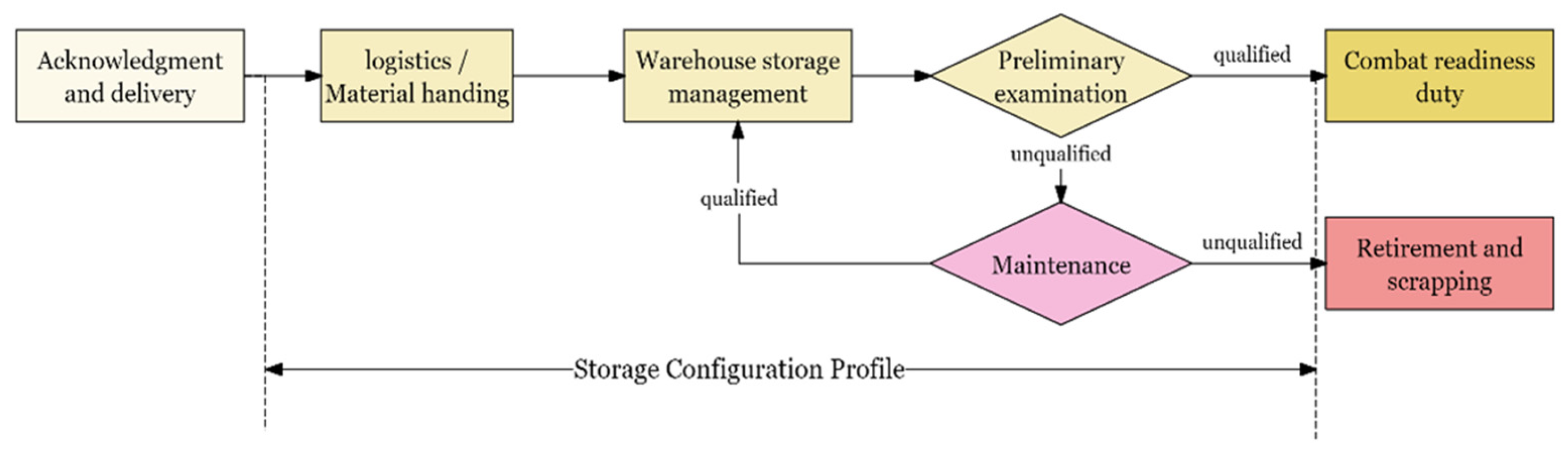
2. Failure Mechanism in the Storage Environment

2.1. Structure and Operational Mechanism

Separation electrical connectors primarily consist of three main components: the plug, the socket, and the locking mechanism. The locking mechanism is integrated into the plug housing, as illustrated in Figure 2, which depicts the structural diagram of a center pull-rod-type separation electrical connector. Figure 3 provides a detailed profile of the locking mechanism (6) in its locked position. The plug and socket springs (8) and (9) are positioned at 120° intervals inside their respective components, and three steel balls are arranged at 120° intervals around the pull rod.
The working process is illustrated in Figure 4. The pull rod, steel balls, and springs are the key components of the unlocking stage. The material sizes and performance parameters of these key components are detailed in Table 1 and Table 2.

2.2. Failure Mechanism Analysis

In the aerospace system, electrical connectors are subjected to an extended storage period, with the storage profile illustrated in Figure 5. Based on the analysis presented in the preceding section, the unlocking phase constitutes a critical stage in the operation of the locking mechanism. Performance variations in key components, specifically the pull rod and spring, under storage conditions may cause the locking mechanism to fail. The central pull-rod-type locking mechanism, as a key component in the model equipment system, generally has the internal parts of the separation point connector stored in a warehouse after leaving the factory. The environmental stresses, it is subjected to mainly include temperature and humidity. There are strict requirements for the storage environment during the storage process. For the locking mechanism, the change in its performance is mainly affected by the temperature stress. The temperature provides the activation energy for the deformation of the pull rod and the stress relaxation of the spring, accelerating the deformation of the pull rod and the stress relaxation of the spring.

2.2.1. Deformation of the Pull Rod

According to Hertz’s contact theory [45], elastic contact between the locking steel ball and the pull rod results in an elliptical contact area when the locking mechanism is locked. Elevated temperatures activate crystal lattice atoms during long-term storage, enhancing dislocation mobility within the material and reducing yield strength. This leads to plastic deformation on the contact surfaces of both the steel ball and the pull rod. As Table 2 indicates, the steel ball (9Cr18) has higher hardness than the pull-rod material (CrWMn), so most deformation occurs on the pull-rod surface.
In an ideal crystal, atoms are arranged in a well-defined and ordered structure [46,47]. According to dislocation theory, actual crystals possess imperfections known as dislocations [48]. Under even minimal applied stress, these dislocations glide, leading to localized distortions in the atomic arrangement. Dislocations can be classified into edge and screw types. As illustrated in Figure 6a, a screw dislocation occurs at point B depicted in the figure, while an edge dislocation occurs at point E depicted in Figure 6b.
Under shear stress, atoms within the dislocation region migrate toward equilibrium positions. As shear stress persists, dislocation defects propagate until they reach the crystal surface, resulting in plastic deformation proportional to the dislocation length. This phenomenon is referred to as slip [49]. Over time, accumulated deformations increase the elliptical contact area on the pull rod’s surface, raising frictional forces between the steel ball and the pull rod, ultimately causing unlocking failure. From a microscopic perspective, at room temperature, the deformation of metals is primarily attributed to dislocation slip within the crystal lattice [50,51]. When the temperature is below 40% of the metal’s melting point T m , dislocation slip predominantly governs the deformation mechanism. According to Table 2, the storage environment temperature is less than 0.4 times the melting point T m of the tie-rod material. Consequently, it can be concluded that in this storage environment, the primary deformation mechanism of the tie rod is dislocation slip within the crystal lattice. According to the time-hardening theory [52], continuous stress causes dislocation formation and accumulation in the material. As dislocation density increases, interactions intensify, resulting in a more complex stress field, higher internal resistance, and material hardening [53]. Over time, this process decreases the deformation rate and increases resistance to dislocation movement, requiring higher activation energy for new deformation mechanisms—these cumulative changes cause macroscopic material hardening.

2.2.2. Stress Relaxation of the Spring
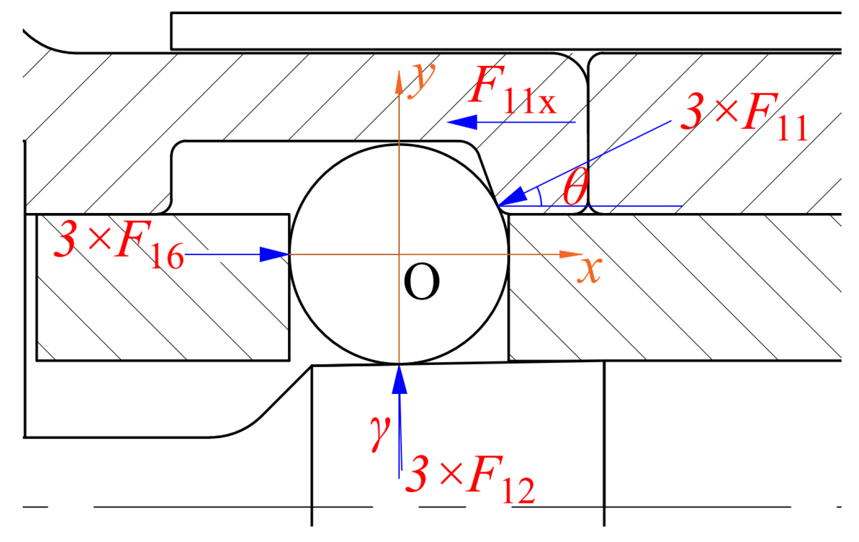
When the central pull-rod-type locking mechanism is engaged, the spring initially experiences elastic deformation. Under sustained compression and environmental stress, this deformation progressively transitions into plastic deformation, decreasing the spring’s internal stress and elastic properties [54]. From a microscopic perspective, when a specific strain is applied to a metal, it generates high internal stress to resist deformation. Over time, the material’s microstructure adapts to this new state. Dislocations in the lattice move to more stable positions, reducing internal energy. Elevated temperatures in storage environments provide activation energy that accelerates dislocation movement within the crystal lattice. However, impurities from heat treatment and processing techniques hinder this movement, causing dislocation locking and impeding stress relaxation. Under long-term storage, dislocation slip is unlikely to occur entirely within the crystal plane. Instead, it is significantly influenced by dislocation accumulation and blocking from precipitates on slip planes that impede dislocation movement [55]. Obstacles within the crystal structure hinder leading dislocations responsible for initiating this movement. Over time, more dislocations accumulate at these precipitates, affecting the leading dislocations through external stress and interaction forces from accumulated dislocations. This accumulation stagnates dislocation slip, impacting the material’s elastic-to-plastic transformation.
In studying temperature’s impact on dislocation slip and pile-up in springs, temperature selection was crucial. Preliminary tests showed slow degradation at 60 °C. To accelerate degradation, the minimum test temperature was set at 105 °C. High temperatures cause spring creep, altering the degradation mechanism. Since smooth-surfaced spring steel’s creep temperature is 300–350 °C, to avoid rapid elastic-force loss and ensure measurement accuracy, the maximum test temperature was set at 158 °C. Thus, samples heated at 105 °C and 158 °C were chosen to study the temperature-related effects. An accelerated testing protocol was employed to simulate long-term storage conditions. Specifically, specimens Figure 7a,c were subjected to identical heating durations, while specimens Figure 7b,d were heated for extended periods under the same conditions. Samples were extracted from the midsection of the spring wires and analyzed using transmission electron microscopy (TEM). Dense networks of slip lines surrounded the black precipitates labeled A, B, C, and D, propagating in the directions indicated by the arrows. Higher temperatures provide more incredible activation energy for dislocations within the crystal lattice, leading to denser slip-line formations for identical heating durations. During the dislocation-slip process, black precipitates are carried along with the dislocations, resulting in pile-ups when slip lines encounter obstacles. This phenomenon slows the stress-relaxation process until the supplied energy is insufficient to overcome the resistance.
In the locking mechanism, the relative displacement of the pull rod does not exceed the diameter of the pull rod and that of the steel balls. Moreover, the three steel balls mutually restrict the maximum movement of the pull rod. During the unlocking stage of the locking mechanism, the spring force far exceeds the frictional force on the contact surface between the steel balls and the pull rod. Therefore, spring stress relaxation stands as a key factor influencing the performance degradation of the locking mechanism.

3. Static Model

The static characteristic analysis of the locking mechanism is critical in achieving a reliable design. This analysis offers essential insights into mechanical performance, establishing a robust reliability research foundation. Examining the mechanism’s mechanical transmission path, a static model for the un-locking phase can be formulated using Hertz’s theory and other relevant principles. The locking state and force condition of the locking steel ball lock are shown in Figure 8.
The horizontal axial force exerted on the locking sleeve can be mathematically formulated as:
F 11 x = 3 · F 8 + F 9 + F 15
where F 9 is the elastic force of the sheath spring (N), F 8 is the elastic force of the plug energy-storage spring (N), and F 15 is the elastic force of the socket energy-storage spring (N).
The axial force F z b generated by the φ3 steel ball on the pull rod can be calculated as follows:
F z b = F s b · cos γ F 12 · sin γ
where F s b is the friction force exerted by the steel ball on the pull rod.
Based on Hertz’s theory [45], the interaction between the φ3 steel ball and the pull rod, illustrated in Figure 9a as the deformation of the pull-rod surface and Figure 9b as a frontal view showing contact stress ( σ 13 - 12 * ), magnitude of deformation ( δ 13 - 12 ), and the major and minor axes of the elliptical projection ( a 13 - 12 and b 13 - 12 , respectively), together with relevant contact parameters derived from the “Mechanical Design Handbook”, ref. [56], are found.
δ 13 - 12 = 0.655 · K 4 · F 12 2 · r 13 + 2 r 12 r 12 · r 13 1 ν 13 2 E n 13 + 1 ν 12 2 E n 12 2 3
a 13 - 12 · b 13 - 12 = 2 · K 1 · K 2 K 4 · r 13 r 12 r 12 + 2 · r 13 · δ 13 - 12
σ 13 - 12 * ( x , y ) = σ 13 - 12 * · 1 x 2 a 13 12 2 y 2 b 13 12 2
where E n 12 and ν 12 are the elastic modulus and Poisson’s ratio of the pull rod, E n 13 and ν 13 are the elastic modulus and Poisson’s ratio of the locking steel ball, respectively, and K 1 , K 2 , K 3 , and K 4 are correction coefficients.
Based on Hertz’s contact theory and the principle of static friction, the frictional force F s b across the entire contact area between the φ3 steel ball and the pull rod can be expressed as:
F s b = f 13 12 · σ 13 12 * ( x , y ) = 2 3 a 13 12 b 13 12 π · σ 13 12 * · f 13 12
where f 13 - 12 is the friction coefficient between the φ3 steel ball and the pull rod.
According to Equations (2) and (6), it can be deduced that the axial resistance exerted by the φ3 steel ball on the pull rod is:
F z b = 2 3 a 13 - 12 b 13 - 12 π · σ 13 - 12 * · f 13 - 12 · cos γ F 11 x 3 · tan θ · tan γ
When the mechanism is in the locked position, and the spring force exerted by the pull-rod spring can be mathematically represented as:
F 18 = k 18 · ( H 0 - 18 H 1 - 18 + S l )
where S l is the displacement of the pull-rod movement.
The unlocking force model for the locking mechanism is established as follows:
F js = 2 a 13 - 12 b 13 - 12 π · σ 13 - 12 * · f 13 - 12 · cos γ F 11 x · tan θ · tan γ + k 18 · ( H 0 - 18 H 1 - 18 + S l )

4. Accelerated Degradation Modeling of the Unlocking Stage

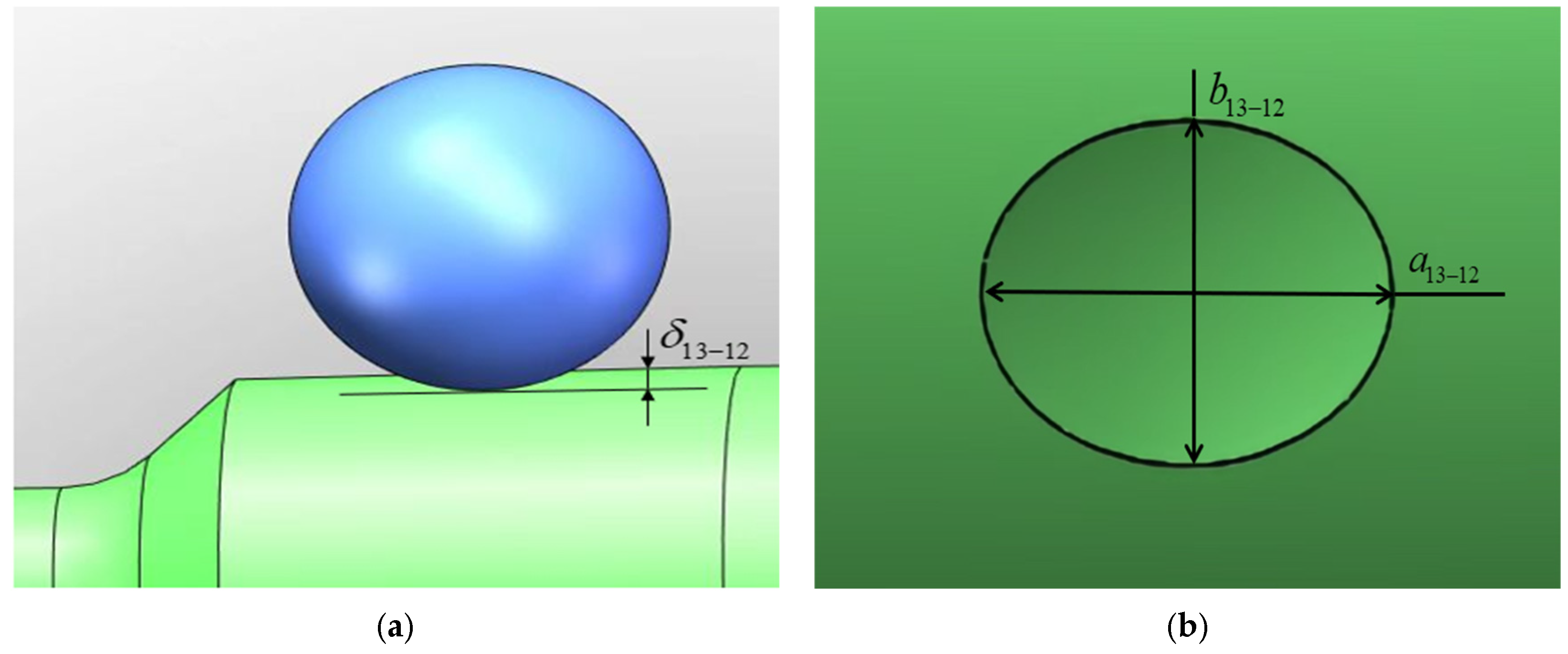
4.1. Accelerated Degradation Modeling of the Steel Ball to Pull-Rod Friction

Metals will gradually undergo plastic deformation under prolonged exposure to constant temperature and stress. This process involves the slip movement of dislocations within the metal’s crystal structure, which is influenced by the applied temperature. Figure 10a illustrates the dislocation movement process within a l 1 × l 2 × l 3 crystal. Figure 10b shows that dislocations exist on specific crystal surfaces and will continuously move to the left under shear stress.
The relationship between dislocation movement and plastic deformation in single crystals of metals can be described as follows:
ϑ i = g c i / l 2 = λ · g c i · l 1 l 3 l 2 · l 1 l 3 = λ · l 1 · l 3 g c i V = S c · l 3 · g c i V
where ϑ i is the plastic deformation amount of the i th crystal, g c i is the strength of dislocations in the i th crystal, and S c is the distance of single-crystal dislocation movement. V is the volume of a single crystal, and l 3 is the width of the crystal, which can be considered equivalent to the width of a dislocation.
Given numerous parallel dislocation lines within the crystal, the j th dislocation can be denoted as l j . The plastic strain rate on the surface of the pull rod can be derived by aggregating the plastic strain of the individual crystal units.
ϑ ˙ 32 31 = ϑ ˙ i = g c i ρ c i v m i = g c ρ c v m
where ρ c i is the dislocation density per unit crystal, indicating the dislocation length per unit volume, v m i is the speed of the slip movement of the dislocation of the i crystal, g c is the superposition of the crystal dislocation strength in the pull rod, and ρ c and v m are the mean dislocation density and mean dislocation-slip velocity of the crystal in the pull rod, respectively.
The relationship between dislocation-slip velocity and stress can be approximately described by the following equation [57]:
v m = M c · σ 13 - 12 * η
where M c is the parameter associated with temperature, and η is the parameter related to material properties.
According to the time-hardening theory [52], by combining Equation (12) with Equation (11), an expression for the deformation rate as a function of both stress σ 13 - 12 * and time t can be derived.
δ ˙ 13 - 12 = M c · ρ c · g c · σ 13 - 12 * η · t q
where q is the parameter associated with the material.
By integrating both sides of Equation (14) from time 0 to time t, it can be deduced that the surface deformation of the pull rod during storage is:
δ 13 - 12 ( t ) = 1 χ + 1 · v c · σ 13 - 12 * η · t q + 1
where v c is the deformation rate of the pull rod, v c = M c · g c · ρ c , and v c is the random variable accounting for the influence of stochastic factors.
Temperature is the primary environmental factor influencing the unlocking and separation performance of the center pull-rod locking mechanism. The Arrhenius equation can be utilized to describe the parameter M c , which is a temperature-dependent variable that reflects the extent to which dislocation movement is influenced by temperature, as follows:
M c = Λ c · exp ( E c K B · T )
where Λ c is the frequency factor, E c is the activation energy of pull-rod deformation (in eV), T is the absolute temperature (K), and K B is the Boltzmann constant.
Combined with the relationship between temperature parameters M c and temperature T , it can be seen that the relationship between deformation rate v c and temperature T is:
ln v c = ln Λ c + ln g c + ln ρ c E c K B · T
Since ln Λ c , ln g c , and ln ρ c are random variables related to material properties, according to the central limit theorem, it is assumed that ln Λ c , ln g c , and ln ρ c follow a normal distribution. Given the additivity property of normally distributed variables, it follows that ln v c also follows a normal distribution. Consequently, v c follows a lognormal distribution, v c L N μ ln v c , σ ln v c .
Let Z 1 = μ ln Λ c + μ ln g c + μ ln ρ c and W 1 = E c / K B , then the formula above can be transformed into:
μ ln v c = Z 1 W 1 T
where Z 1 and W 1 are the parameters to be estimated.
By substituting the strain–time relationship from Equation (14) into Equation (6), we can derive the degradation model of ejector resistance as follows:
F s b ( t ) = 4 3 · K 1 · K 2 K 4 · r 12 r 13 r 13 + 2 · r 12 · π · f 13 - 12 · 1 χ + 1 · v c · σ 13 - 12 * η + 1 · t q + 1

4.2. Accelerated Degradation Modeling of the Spring Force

The stress relaxation of a spring refers to the situation where under a certain temperature and pressure, the spring is subjected to a constant strain, and the stress will decrease over time, resulting in insufficient elastic force of the spring. Considering the spring’s long-term storage environment and condition, its total strain remains constant, while the internal elastic and plastic strains undergo mutual transformation. Therefore, the time derivatives of the total strain γ t , the elastic strain γ p , and the plastic strain γ e can be obtained as follows:
γ ˙ p + γ ˙ e = γ ˙ t = 0
Drawing upon the preceding analysis and the principles of dislocation-slip theory [48,49], it is evident that the expression for the plastic strain rate of the spring influenced by dislocations can be derived as follows:
γ ˙ e = A ρ ¯ B ( τ * ) m
where A is the cumulative dislocation strength within the crystal lattice of the spring, is the average velocity of mobile dislocations within the spring, B and m are parameters dependent on temperature and hardness, τ * is the effective shear stress.
As illustrated in Figure 11, if the leading dislocation x 0 is taken as the origin, x 1 , x 2 , x i represent the distances of the subsequent piled-up dislocations from the leading dislocation [58]. These i dislocations can collectively be considered a large dislocation with an equivalent intensity. Therefore, the mechanical equilibrium equation at the point x j during the dislocation pile-up process can be expressed as [59]:
i G A 2 2 π ( 1 v ) × 1 x j + i G A 2 2 π ( 1 v ) × q = j + 1 i 1 x q x j = τ A
where G is the material’s shear modulus, v is the Poisson’s ratio of the material, τ is the applied shear stress on the material.
Over time, dislocations progressively accumulate as a result of impurity-induced obstruction. Previous studies have shown that the density of mobile dislocations versus time follows a hyperbolic trend [60]. Considering pile-up effects, the expression for mobile dislocation density can be formulated as:
ρ = e t + p
where p is the degree of dislocation accumulation. For the spring in long-term storage, the dislocations accumulated at the later stage of relaxation remain in equilibrium, and this value will also be a constant. t is the time, and e is the crystal scale parameter.
By substituting Equation (22) into Equation (20), we can derive the equation that describes the time-dependent variation in the plastic strain rate influenced by dislocation pile-up:
γ ˙ e = e t + p A B ( τ * ) m
Based on the material stress-relaxation mechanism, the plastic strain formula (Equation (23)) is substituted into the elastic–plastic strain equation (Equation (19)). Subsequently, the resulting equation is integrated from 0 to the specified stress-relaxation time t , deriving the expression for the stress loss rate during the spring storage process.
τ 0 τ t τ 0 = [ ( m 1 ) A B G e τ 0 1 m · ln ( t p + 1 ) ] 1 1 m
After the transformation, the maximum shear stress experienced by the spring under compression on both sides of this equation is a superposition of torsional and transverse shear stresses. Consequently, the magnitude of the shear stress τ in the storage spring can be expressed as:
τ = 8 F 0 D π d 3 ( 1 + 1 2 c )
where F 0 is the pressure exerted on the spring, D is the mean diameter of the spring, d is the diameter of the spring wire, and c is the spring index, which is defined as the ratio of the mean diameter ( D ) to the diameter of the spring wire ( d ).
Under long-term storage conditions, the hardness of the spring remains constant, that is, m = 0 . The performance degradation model for the spring during the storage period can be expressed as:
F t = F 0 v s [ ln ( t p + 1 ) ]
where
v s = A B G e H H = π d 3 8 D ( 1 + 1 2 c )
where F t is the elastic force measured after the sample has been removed from the constant temperature test chamber at time t during the test, allowed to cool to room temperature, and subsequently compressed to the assembly height. v s is a random variable that represents the degradation rate of the spring.
According to the theory of thermal expansion, given the relatively minor temperature variations under the specified storage conditions for the spring, it can be reasonably assumed that G t G 0 .
Based on the relaxation mechanism, temperature supplies adequate activation energy to promote dislocation movement. The relationship between the spring temperature parameter M s and thermal stress is characterized by the Arrhenius equation as follows:
M s = Λ s · exp ( E s K B · T )
where Λ s is the frequency factor, E s is the absolute activation energy (in eV), and T is the absolute temperature (K).
By integrating the relationship between the elastic modulus and the temperature parameter B , as well as considering the effect of temperature, the relationship between the relaxation rate v s of the spring and the temperature stress can be simplified as follows:
ln v s = ln A s E s K B · T
where A s = b G 0 e H Λ is the cumulative product of various design and material parameters, including dislocation strength ( b ), shear modulus ( G 0 ), crystal scale parameter ( e ), and spring-size parameter ( H ). By the central limit theorem, A s is characterized by a log-normal distribution. Consequently, v s L N ( u v s , σ v s 2 ) , where u v s and σ v s 2 are the logarithmic mean and logarithmic standard deviation of the spring’s relaxation rate, respectively.
Let Z 2 = μ ln A s and W 2 = E s / K B ; then, the formula above can be transformed into:
u v s = Z 2 W 2 T
where Z 2 is a model parameter, W 2 = E s K b .

4.3. Reliability Model of the Unlocking Stage

The investigation of the center pull-rod-type locking mechanism reveals a decreasing trend in its unlocking force. When the unlocking force falls below the failure threshold F 1 , an unlocking failure occurs. The reliability of the central pull-rod locking mechanism at time t can be expressed as:
R ( t ) = P 3 F s b ( t ) · cos γ 3 F 12 ( t ) · sin γ + F 18 ( t ) F 1 > 0
where R ( t ) is the unlocking reliability at time t, F 1 is the failure threshold of the locking and separation mechanism. For the central pull-rod-type locking and separation mechanism examined in this study, the failure threshold F 1 is determined to be 35 N [61].

5. Validation of the Accelerated Degradation Model

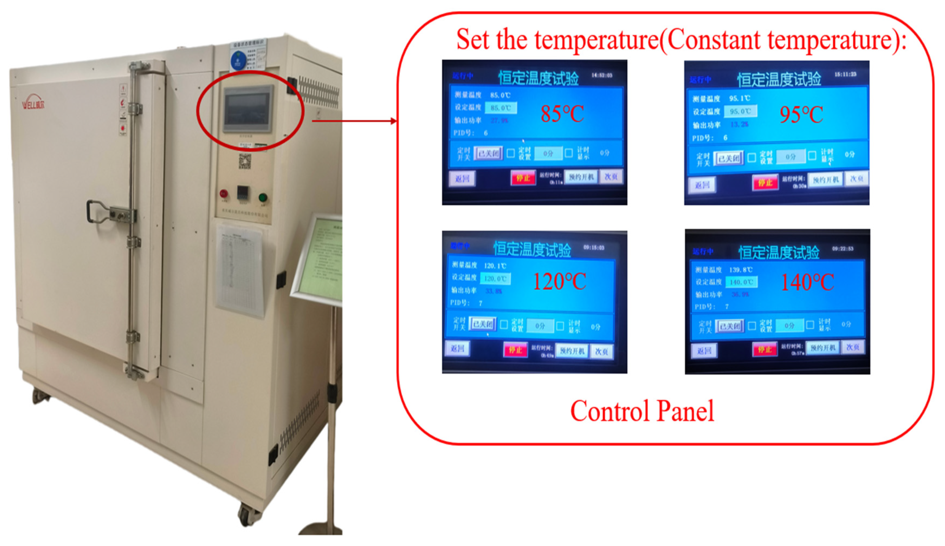
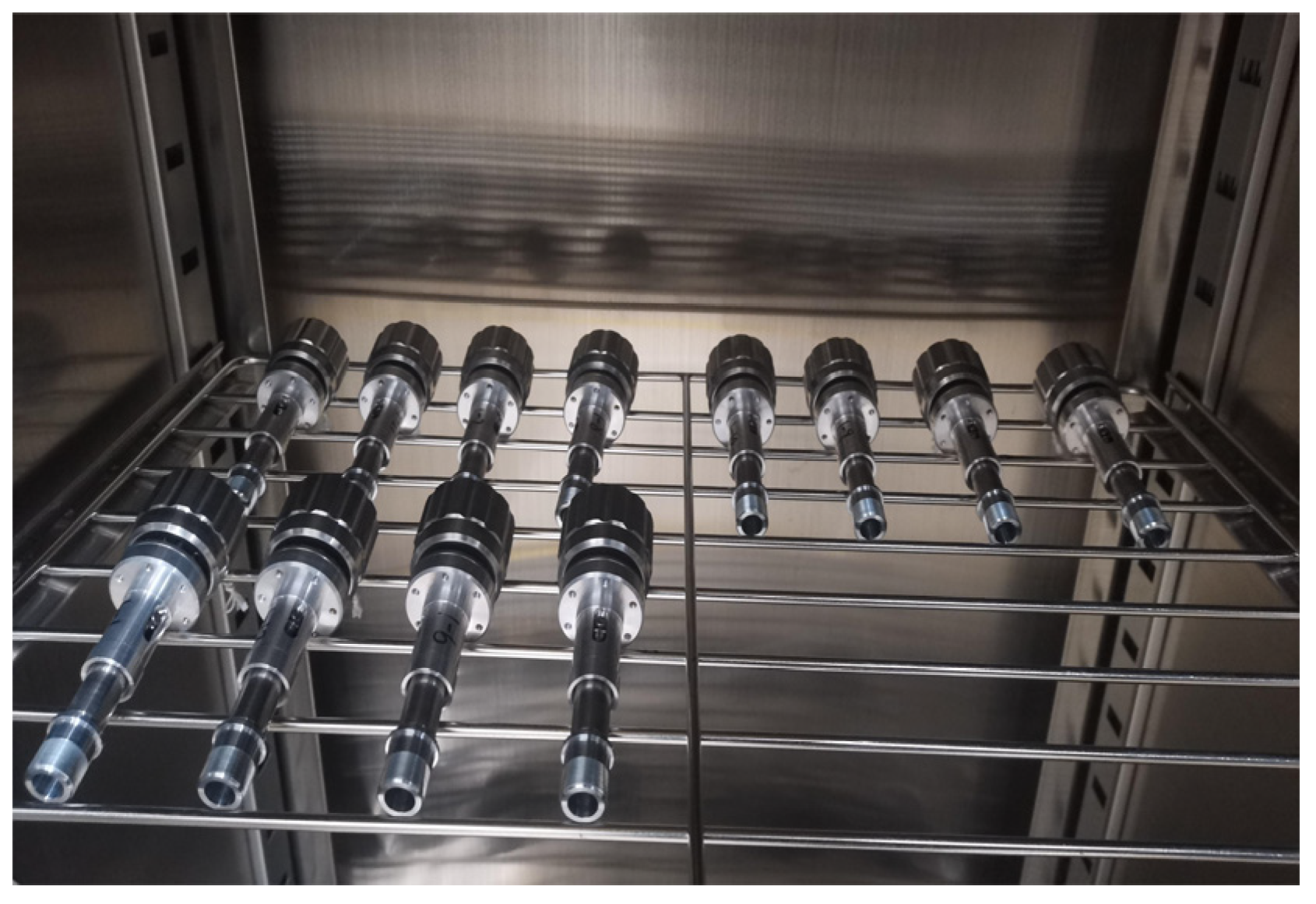
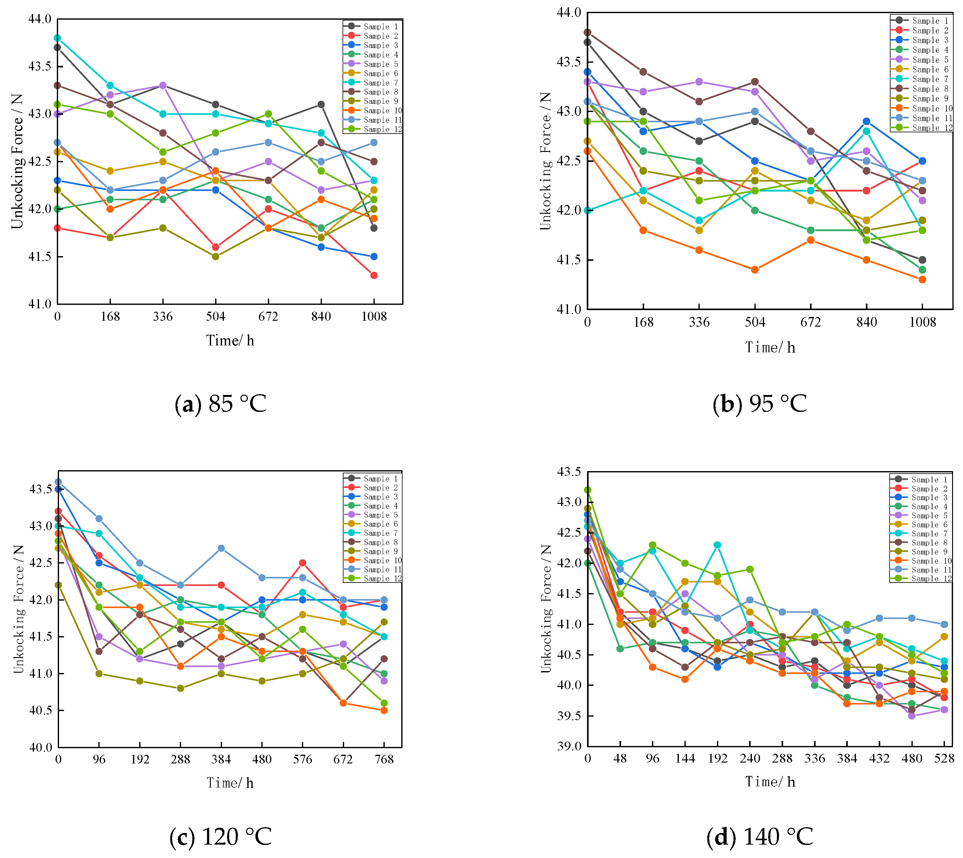
5.1. Accelerated Test Protocol

Given the maturity and accuracy of the Constant Stress Accelerated Test (CSAT) theory, this paper adopts CSAT as the testing methodology. Based on Section 2’s storage profile analysis, varying temperatures are used as accelerating stresses. Following GB/T 2689.1-1981 [62], four stress levels ( T 1 = 85   ° C , T 2 = 95   ° C , T 3 = 120   ° C , T 4 = 140   ° C ) are employed with cut-off times of 1000 h, 1000 h, 700 h, and 500 h, respectively, and test intervals of 168 h, 168 h, 96 h, and 48 h. To ensure performance degradation without altering the failure mechanism, 12 identical mechanisms are tested at each stress level. The test equipment is shown in Figure 12. The temperature range of the equipment was 35–300 °C, and the temperature error range was controlled within ±0.5 °C. The accelerated test procedure is illustrated in Figure 13. By the GB/T 43369-2323 standard specification [63] and the electrical-connector product design manual [61], a force ranging from 35 N to 100 N should be applied along the axial direction of the pull rod. This force causes the locking mechanism to unlock. During this operation, the maximum included angle between the applied force and the axis of the pull rod must not exceed 15°, and the tensile speed during testing must not exceed 200 mm/min. Considering the above test requirements, the test apparatus is illustrated in Figure 14. The device is composed of three parts: a screw frame, a dynamometer, and a cross slide. The dynamometer is installed on the screw lifting platform of the screw frame and moves up and down in the direction perpendicular to the base together with the screw lifting platform. The cross slide is fixed to the base of the screw frame with bolts and is used to fix the test sample.

5.2. Statistical Analysis of Accelerated Test Data

Figure 15 presents a point-line graph depicting the variation in the unlocking force of the locking and separating mechanism over time at different temperatures. Each data point corresponds to the unlocking force observed at a specific temperature and heating duration. The figures show that the unlocking force is decreasing, with an initial rapid decline followed by a gradual slowdown. This phenomenon becomes increasingly pronounced as the temperature increases. Since the deformation of the pull rod will cause an increase in the unlocking force, and the amount of deformation is limited by the size of the steel ball and the pull rod, while the overall pattern shows a downward trend, it can be concluded that the stress relaxation of the spring is the main cause of the failure of the locking mechanism. During the stress-relaxation process of the spring, the internal dislocation pile-up gradually increases. Therefore, the overall curve exhibits a downward trend that is initially rapid and then slows down.

5.3. Parameter Estimation

The institutional unlocking-force model parameters were estimated using the particle-swarm optimization algorithm [64]. The mean values from four test data sets were used for initial parameter estimation. Then, the measured data from each sample were input into the model to calculate the logarithmic standard deviation ( σ ln v c ) at different stress levels. Notably, σ ln v c can be determined using the following formula:
σ ln v c = 1 N s a m p l e · 1 N s a m p l e μ ln v c ln v c i 2
where N sample is the sample size of the test, while v c i is the estimated value of v c for the ith sample.
The estimation results are presented in Table 3, Table 4, Table 5 and Table 6.

5.4. Verification of the Degradation Trajectory Model

The approximation between the fitting and measured values F js i ( i = 1 , 2 N test ) can be used as the standard to measure the accuracy of the curve fitting of the mathematical model. The correlation coefficient R NL of the curve-regression-fitting accuracy index was defined as [65]:
R NL = 1 i = 1 N test F js i F ^ js i 2 i = 1 N test F js i 2
where N test is the number of test points, F js i ( i = 1 , 2 N test ) is the measured value of the unlocking force, and F ^ js i is the fitted value of the unlocking force.
The value range for R NL is (0, 1), with values closer to 1 indicating a higher degree of model fit. The goodness of fit at the four stress levels is presented in Table 7. Consequently, verifying the accuracy of the unlocking-force degradation trajectory model.

6. Conclusions

This paper presents a model to understand the reliability of center pull-rod-type locking mechanisms by analyzing the failure mechanisms of deformation of the pull rod and stress relaxation in the spring. This paper utilizes a mechanical model to investigate the relationship between the unlocking force and the design parameters of the locking mechanism. This analysis provides insight into how critical design parameters, including spring dimensions, pull-rod dimensions, and pull-rod angle, influence the reliability of the center pull-rod locking mechanism.
Additionally, this paper investigates the impact of storage environments on the reliability of the locking mechanism by integrating crystal slip, pull-rod hardening, and internal dislocation accumulation within the spring. It examines the thermal activation processes associated with pull-rod deformation and spring stress relaxation to determine their respective deformation and stress-relaxation laws. By incorporating these factors, this study establishes an accelerated degradation trajectory model for the pull rod and spring, which integrates design parameters to predict the reliability of the locking mechanism.
This paper conducts an accelerated degradation test on the center pull-rod-type locking mechanism to validate the proposed model. The test data are analyzed using the Particle Swarm Optimization (PSO) algorithm to determine the model’s key parameters. The experimental results demonstrate that the proposed model accurately captures the degradation process of the unlocking force, thereby verifying the model’s correctness and reliability.
In conclusion, this paper develops an accelerated degradation model for the locking mechanism by incorporating the deformation of the pull rod and the stress relaxation of the springs while accounting for the design parameters. The model has been rigorously validated through accelerated degradation tests, demonstrating its rationality and accuracy.
However, the object of this study is a manually separated locking mechanism. In addition to the manually separated type, there is also an electrically separated locking mechanism. In the future, research on the electrically separated locking mechanism can be carried out by combining the performance degradation of electromagnetic components. The performance degradation trajectory model established in this paper only considers the influence of the deformation of the ejector rod and the stress relaxation of the spring after long-term storage. In the future, it is possible to consider establishing a performance degradation model under actual usage conditions, which will provide a richer reference for the evaluation of the locking mechanism.

Author Contributions

Conceptualization, P.Q. and T.T.; methodology, P.Q.; validation, W.C., F.Y. and C.C.; data curation, T.T.; writing—original draft preparation, T.T.; writing—review and editing, T.T.; visualization, Y.Z.; supervision, Y.Z.; funding acquisition, P.Q. and F.Y. All authors have read and agreed to the published version of the manuscript.

Funding

This study was supported by Key Research and Development Project of Zhejiang Province with No. 2021C01133 and the National Natural Science Foundation of China with No. 52305151.

Data Availability Statement

The data that have been used are confidential.

Acknowledgments

The completion of this study is due to the collaborative efforts of several co-authors.

Conflicts of Interest

The authors declare no conflicts of interest.

Abbreviations

A cumulative dislocation strength within the crystal lattice of the spring
A s cumulative product of various design and material parameters
a major axes of the elliptical projection
B parameters dependent on temperature
b minor axes of the elliptical projection
c spring index
D the mean diameter of the spring
d diameter of the spring wire
E activation energy
E n elastic modulus
e crystal scale parameter
F force
F z b axial force generated by the φ3 steel ball on the pull rod
F s b friction force exerted by the steel ball on the pull rod
f friction coefficient
G material’s shear modulus
g c strength of dislocations in the crystal
H height
K correction coefficient
K B Boltzmann constant
l width of the crystal
M parameter associated with temperature
m parameters dependent on hardness
N sample size of the test
p degree of dislocation accumulation
q parameter associated with the material
R NL correlation coefficient
R ( t ) unlocking reliability at time t
S c distance of single-crystal dislocation movement
S l displacement of the pull-rod movement
T absolute temperature
t time
u logarithmic mean
V volume of a single crystal
v Poisson’s ratio of the material
v m speed of the slip movement of the dislocation of the crystal
v s degradation rate of the spring
v c deformation rate of the pull rod
W parameters to be estimated
x distances of the subsequent piled-up dislocations from the leading dislocation
Z parameters to be estimated
σ logarithmic standard deviation
σ * contact stress
γ The cone angle of the pull rod
δ magnitude of deformation
ϑ plastic deformation amount of the crystal
ρ the dislocation density per unit crystal
η parameter related to material properties
Λ the frequency factor
γ plastic strain
τ applied shear stress on the material
τ * effective shear stress
θ contact angle between the lock sleeve and the steel ball

References

  1. Xin, L.; Feng, C.; Lv, W.; Zhou, Y.; Xiong, C.; Gao, Y.; Zhu, F. Electrical contact reliability investigation of high-speed electrical connectors under fretting wear behavior. Microelectron. Reliab. 2024, 115, 115510. [Google Scholar]
  2. Lin, M. Study on the Influence of Closing Quantity and Plating Thickness on the Storage Life of Contact Parts. Master’s Thesis, Zhejiang University of Science and Technology, Hangzhou, China, 2023. [Google Scholar]
  3. Wu, Y.J. Research on the Influence Law of Shell Nosing of Contact on the Storage Life. Master’s Thesis, Zhejiang University of Science and Technology, Hangzhou, China, 2022. [Google Scholar]
  4. Xie, S.W. Research on the Effects of Gold-Plated Thickness on the Storage Life of Cylindrical Slot Contacts. Master’s Thesis, Zhejiang University of Science and Technology, Hangzhou, China, 2022. [Google Scholar]
  5. Qin, B.; Zhang, Y. Comprehensive analysis of electro-mechanical characteristics and new regression models of a novel slanted groove electrical connector. Int. J. Non-Linear Mech. 2024, 104, 104863. [Google Scholar] [CrossRef]
  6. Liang, S.Y. Research on the Effects of Wire-Spring Angleon the Reliability of Electrical Connector Contacts. Master’s Thesis, Zhejiang University of Science and Technology, Hangzhou, China, 2023. [Google Scholar]
  7. Guo, H.J.; Liang, S.Y.; Chen, W.H.; Zhong, L.; Chen, Z.; Yan, J. Research on influence of wire spring inclination angle on storage life of wire spring hole electrical connector. Chin. J. Eng. Des. 2023, 30, 390–398. [Google Scholar]
  8. Qian, P.; Ma, Z.; Chen, W.; Zhang, T.; Wang, Z. Contact reliability modeling and assessment of electrical connectors with multi-aperture slotted leaf spring contacts. Adv. Mech. Eng. 2023, 15, 168781322311807. [Google Scholar] [CrossRef]
  9. He, W.; Feng, Y.; Wu, S.; Wang, W. Numerical study on thermal-electrical-mechanical coupling mechanism of electrical connectors considering contact resistance. Proc. Inst. Mech. Eng. Part C J. Mech. Eng. Sci. 2024, 5, 1699–1712. [Google Scholar] [CrossRef]
  10. Shukla, A.; Martin, R.; Probst, R.; Song, J. Comparison of different statistical methods for prediction of lifetime of electrical connectors with short term tests. Microelectron. Reliab. 2023, 150, 115216. [Google Scholar] [CrossRef]
  11. Siddaiah, A.; Kasar, A.K.; Khosla, V.; Menezes, P.L. In-situ fretting wear analysis of electrical connectors for real system applications. J. Manuf. Mater. Process. 2019, 3, 47. [Google Scholar] [CrossRef]
  12. Wang, Y. Study on Reliability Modeling and Test Evaluation of G100 Silicone Rubber Insulator for Electrical Connectors. Master’s Thesis, Zhejiang University of Science and Technology, Hangzhou, China, 2023. [Google Scholar]
  13. Liu, X. Study on the Influence of Temperature and Humidity on the Insulation Performance of Polyurethane Adhesive for Electrical Connectors. Master’s Thesis, Zhejiang University of Science and Technology, Hangzhou, China, 2023. [Google Scholar]
  14. Jiang, H. The effect of environmental temperature and insulation materials on the insulation resistance of electrical connectors. Electron. Technol. Softw. Eng. 2021, 10, 222–223. [Google Scholar]
  15. Qian, P.; Liu, X.; Chen, W.; Wang, Z.; Guo, M. Storage reliability modeling of polyurethane seals for electrical connectors. J. Mech. Eng. 2024, 20, 361–371. [Google Scholar]
  16. Chen, T. Research on the Storage Life Assessment of 771 Silicone Seals for Electric Connectors. Master’s Thesis, Zhejiang Sci-Tech University, Hangzhou, China, 2022. [Google Scholar]
  17. Angadi, S.V.; Jackson, R.L.; Pujar, V.; Tushar, M.R. A comprehensive review of the finite element modeling of electrical connectors including their contacts. IEEE Trans. Compon. Packag. Manuf. Technol. 2020, 10, 836–844. [Google Scholar] [CrossRef]
  18. Hilmert, D.; Yuan, H.; Song, J. The analysis of failure mechanisms of electrical connectors in long-term use field vehicles. In Proceedings of the 2022 IEEE 67th Holm Conference on Electrical Contacts (HLM), Tampa, FL, USA, 23–26 October 2022; IEEE: Piscataway, NJ, USA, 2022; pp. 1–8. [Google Scholar]
  19. Krüger, K.; Song, J. The influence of thermal cycling test parameters on the failure rate of electrical connectors. Microelectron. Reliab. 2022, 138, 114633. [Google Scholar] [CrossRef]
  20. Song, J.; Shukla, A.; Probst, R. The state of health of electrical connectors. Machines 2024, 12, 474. [Google Scholar] [CrossRef]
  21. Liu, S. Motion Reliability Analysis and Optimization Design of Planar Linkage Mechanisms Under Hybrid Uncertainty. Doctoral Dissertation, Wuhan University of Science and Technology, Wuhan, China, 2023. [Google Scholar]
  22. Liu, S.; Wang, X.; Kong, J.; Zeng, T.; Tang, W. Kinematic reliability analysis of planar metamorphic mechanisms with multi-source uncertainties. J. Mech. Eng. 2021, 17, 64–75. [Google Scholar]
  23. Feng, Y.S. Research on mechanism reliability theory. China Mech. Eng. 1992, 3, 4–6. [Google Scholar]
  24. Feng, Y.S. Wear reliability of mechanism. Acta Aeronaut. Astronaut. Sin. 1993, 12, 642–644. [Google Scholar]
  25. Xue, Z.; Feng, W.; Wang, W.; Xiong, X.; Wang, S. Motion reliability analysis of a folding arm mechanism based on the first-order second-moment method. Hoisting Transp. Mach. 2022, 19, 8–13. [Google Scholar]
  26. Li, Y.; Shang, D.; Fan, X.; Liu, Y. Motion reliability analysis of the delta parallel robot considering mechanism errors. Math. Probl. Eng. 2019, 2019, 3501921. [Google Scholar] [CrossRef]
  27. Yao, Q.; Zhang, Q.; Tang, J.; Wang, X.; Hu, M. Time-variant reliability analysis method for uncertain motion mechanisms based on stochastic process discretization. IEEE Access 2022, 10, 49040–49049. [Google Scholar] [CrossRef]
  28. Chen, X.; Gao, S. Dynamic accuracy reliability modeling and analysis of planar multi-link mechanism with revolute clearances. Eur. J. Mech. A-Solids 2021, 90, 104317. [Google Scholar] [CrossRef]
  29. Chen, X.; Gao, S. Dynamic response and dynamic accuracy reliability of planar mechanism with multiple lubricated clearances. Multibody Syst. Dyn. 2023, 57, 1–23. [Google Scholar] [CrossRef]
  30. Yang, Y.; Wang, M. Modeling and analysis of position accuracy reliability of R(RPS&RP) & 2-UPS parallel mechanism. J. Mech. Eng. 2023, 59, 62–72. [Google Scholar]
  31. Gao, Y.; Xiao, F.; Liu, J.; Wang, R. Distributed soft fault detection for interval type-2 fuzzy-model-based stochastic systems with wireless sensor networks. IEEE Trans. Ind. Inform. 2019, 15, 334–347. [Google Scholar] [CrossRef]
  32. Lv, J.; Yu, Z.; Zhang, H.; Sun, G.; Muhl, P.; Liu, J. Transformer based long–term prognostics for dynamic operating PEM fuel cells. IEEE Trans. Transp. Electrif. 2024, 10, 1747–1757. [Google Scholar] [CrossRef]
  33. Lv, J.; Kuang, J.; Yu, Z.; Sun, G.; Liu, J.; Leon, J.I. Diagnosis of PEM fuel cell system based on electrochemical impedance spectroscopy and deep learning method. IEEE Trans. Ind. Electron. 2024, 71, 657–666. [Google Scholar] [CrossRef]
  34. Chang, X.; Zhang, Z.; Yang, Z.; Zhen, E.; Wang, J. Technical discussion on the locking and unlocking scheme of the gas-liquid connector of the launch vehicle. Missiles Space Veh. 2021, 5, 99–103. [Google Scholar]
  35. Yang, F. Reliability Design Method of Locking Mechanism for Electric Connectors. Doctoral Dissertation, Zhejiang Sci-Tech University, Hangzhou, China, 2017. [Google Scholar]
  36. Chen, W.H.; Du, S.L.; Yang, F.; Pan, J.; Qian, P. Unlocking reliability analysis of the ball locking mechanism for separating electrical connectors. Chin. J. Eng. Des. 2017, 24, 280–285. [Google Scholar]
  37. Mealier, N.; Dau, F.; Guillaumat, L.; Arnoux, P. Reliability assessment of locking systems. Probabilistic Eng. Mech. 2010, 25, 67–74. [Google Scholar] [CrossRef]
  38. Tan, Z.Q.; Wang, S.J.; Zhao, M.Y. Movement function reliability of limit-locking mechanism of space cable-strut deployable articulated mast. Appl. Mech. Mater. 2013, 365–366, 344–350. [Google Scholar] [CrossRef]
  39. Hao, S. Reliability Analysis and Optimum Design of Key Component of the Locking Separation Mechanism of Electrical Connector. Master’s Thesis, Zhejiang Sci-Tech University, Hangzhou, China, 2016. [Google Scholar]
  40. Zhuang, Y.; Xie, Z.; Wang, B.; Wang, W.; Li, W.; Wang, Y. Design and analysis for a novel docking mechanism with T-type locking structure in space. In Proceedings of the 2019 IEEE 9th Annual International Conference on Cyber Technology in Automation, Control, and Intelligent Systems (CYBER), Suzhou, China, 29 July–2 August 2019; IEEE: Piscataway, NJ, USA, 2019; pp. 1085–1090. [Google Scholar]
  41. Wang, D.; Zhang, C.; Deng, J.; Cao, Y. Structure design of high-precision small theodolite shaft locking mechanism. Dev. Innov. Mach. Electr. Prod. 2024, 4, 34–36. [Google Scholar]
  42. Zhang, Q.; Zhang, L.; Zhang, W.; Xu, J.; Yang, Y.; Rao, W. Rapid Locking Mechanism for Electrical Connectors and Electrical Connectors. China Patent No. 201810562963, 3 July 2021. [Google Scholar]
  43. Chen, S.; Li, S.; Sun, J. Construction and evaluation method of fuzzy reliability life model for spherical joints based on accuracy, (Engineering Edition). J. Zhejiang Univ. 2025, 59, 626–634. [Google Scholar]
  44. Huang, L.; Li, X.; Zhang, W. Design and experimental research of electromagnetic hold down and release mechanism. J. Mach. Des. 2024, 4, 102–109. [Google Scholar]
  45. Popov, V.L. Contact Mechanics and Friction: Physical Principles and Applications; Tsinghua University Press: Beijing, China, 2010. [Google Scholar]
  46. Qian, L. A historical review of the study of crystal defects. Physics 1980, 9. [Google Scholar]
  47. He, X.; He, L.; Tang, M.; Xu, M. Effects of the vacancy point defect on electronic structure and optical properties of LiF under high pressure: A first-principles investigation. Acta Phys. Sin. 2011, 60, 547–551. [Google Scholar]
  48. Shi, D. Fundamentals of Materials Science; China Machine Press: Beijing, China, 2021. [Google Scholar]
  49. Liu, Q. Research progress on plastic deformation mechanism of Mg alloys. Acta Metall. Sin. 2010, 46, 1458–1472. [Google Scholar] [CrossRef]
  50. Zhang, S. Creep property and mechanism of AZ31 magnesium alloy under high temperature and low stress. J. Mech. Eng. 2009, 45, 291–295. [Google Scholar] [CrossRef]
  51. Li, J. Research on the Behavior and Mechanism of Short-Time High-Temperature Creep and Stress Relaxation of Fine Grain TC21 Titanium alloy; Harbin Institute of Technology: Harbin, China, 2014. [Google Scholar]
  52. Mu, X. Creep Mechanics; Xi’an Jiaotong University Press: Xi’an, China, 1990. [Google Scholar]
  53. Sadeghi, B.; Shabani, A.; Heidarinejad, A.; Laska, A.; Szkodo, M.; Cavaliere, P. A quantitative investigation of dislocation density in an Al matrix composite produced by a combination of micro-/macro-rolling. J. Compos. Sci. 2022, 6, 199. [Google Scholar] [CrossRef]
  54. Hariharan, K.; Majidi, O.; Kim, C.; Lee, M.; Barlat, F. Stress relaxation and its effect on tensile deformation of steels. Mater. Des. 2013, 52, 284–288. [Google Scholar] [CrossRef]
  55. Johnston, W.G.; Gilman, J.J. Dislocation velocities, dislocation densities, and plastic flow in lithium fluoride crystals. J. Appl. Phys. 1959, 30, 764–775. [Google Scholar] [CrossRef]
  56. Wen, B. Manual of Mechanical Design, 5th ed.; China Machine Press: Beijing, China, 2010. [Google Scholar]
  57. Zhao, J. Fundamentals of Materials Science, 3rd ed.; Higher Education Press: Beijing, China, 2021. [Google Scholar]
  58. Zhang, X. A continuum model for dislocation pile-up problems. Acta Mater. 2017, 128, 428–439. [Google Scholar] [CrossRef]
  59. Anderson, P.H.; Lothe, J. Theory of Dislocations, 3rd ed.; Cambridge University Press: Cambridge, UK, 2017. [Google Scholar]
  60. Xiao, L. Study on Stress Relaxation Properties and Microstructure Changes of Copper Alloys; Tianjin University: Tianjin, China, 1990. [Google Scholar]
  61. Hangzhou Aerospace Electronics Technology Co., Ltd. Electrical Connector Product Manual; Hangzhou Aerospace Electronics Technology, Co., Ltd.: Hangzhou, China, 2015. [Google Scholar]
  62. GB 26891-81; General Rules for Constant Stress Life Testing and Accelerated Life Testing. Ministry of Fourth Machinery Industry of the People’s Republic of China, National Standardization Administration: Beijing, China, 1981.
  63. GB/T 43368-2023; National Standardization Management Committee: General Specifications for Aerospace Separation and Dropping Connectors. China Standards Press: Beijing, China, 2023.
  64. Ji, Z. Particle Swarm Algorithm and Its Applications; Science Press: Beijing, China, 2009. [Google Scholar]
  65. Zhang, S.Q. Approach on the Fitting Optimization Index of Curve Regression. Chin. J. Health Stat. 2002, 1, 9–11. [Google Scholar]
Figure 1. Research method framework diagram based on concept map.
Actuators 14 00205 g001
Figure 2. A product structure diagram of a center pull-rod-type separation electrical connector: 1—socket-cable cover; 2—jack; 3—socket active layer; 4—pin; 5—plug-cable cover; 6—locking mechanism; 7—plug-fixing insulation board; 8—plug spring; 9—socket spring; 10—socket-fixing insulation board; 11—locking sleeve.
Actuators 14 00205 g002
Figure 3. A product structure diagram of a center pull-rod type locking mechanism: 12—pull rod; 13—φ3 steel ball; 14—protective sheath; 15—sheath spring; 16—connecting tube sleeve; 17—screw; 18—pull-rod spring; 19—bushing; 20—handwheel.
Actuators 14 00205 g003
Figure 4. A schematic diagram of the unlocking and separation process for the locking mechanism.
Actuators 14 00205 g004
Figure 5. Storage profile of model equipment.
Actuators 14 00205 g005
Figure 6. Slip motion of dislocations in crystals. (a) spiral dislocation. (b) Edge dislocation.
Actuators 14 00205 g006
Figure 7. Transmission electron microscopy (TEM) analysis of the spring.
Actuators 14 00205 g007aActuators 14 00205 g007b
Figure 8. A force analysis diagram of the locking steel ball. F 11 x —the axial force exerted by the locking sleeve; F 11 —the positive pressure applied by the lock sleeve on the steel ball; F 12 —the positive pressure exerted by the pull rod on the steel ball; F 16 —the normal pressure applied by the connecting tube sleeve on the steel ball; θ —the contact angle between the lock sleeve and the steel ball; γ —the cone angle of the pull rod.
Actuators 14 00205 g008
Figure 9. The surface deformation of the pull rod. (a) Front view of the contact area between the pull rod and the steel ball. (b) Top view of the surface deformation on the pull rod.
Actuators 14 00205 g009
Figure 10. Schematic illustration of crystal misalignment. (a) The state of the crystal without dislocation occurring. (b) After the dislocation movement occurs in the crystal.
Actuators 14 00205 g010
Figure 11. Dislocation pile-up induced by obstacles.
Actuators 14 00205 g011
Figure 12. High-temperature test chamber.
Actuators 14 00205 g012
Figure 13. Procedure for the acceleration test.
Actuators 14 00205 g013
Figure 14. The measuring apparatus.
Actuators 14 00205 g014
Figure 15. Degradation trajectories of unlocking force at different temperatures.
Actuators 14 00205 g015
Table 1. Design parameters of the spring for a central pull-rod locking mechanism.
NumberNameShear Modulus G (MPa) Wire Diameter d (mm)Mean Diameter D (mm)Effective Laps
n
Free Height H0 (mm)Assembly Height H1 (mm)
8Plug79,8000.74.61021.419
9Spring Socket Spring79,8001.25.31329.726.2
15Sheath Spring79,80019.55.7528.514.7
18Pull-Rod Spring79,8000.95.11327.817.2
Table 2. Material performance parameters of the pull rod and locking steel balls.
NumberNameMaterialElastic Modulus E/MPaPoisson’s Ratio v(Equivalent) Radius r/mmMelting Point Tm/°CHardness
HRC
12Pull RodCrWMn220 × 1030.291.93137040–60
13φ3 Steel Balls9Cr18232 × 1030.281.5140061–66
Table 3. Estimated values of model parameters.
Parameter f 13 12 q η p s
Estimated value0.6−0.7−10.844.42
Table 4. Estimated values of σ ln v .
Parameter σ ln v c σ ln v s
Computed value0.620.1
Table 5. Estimated values of Z 12 and W 12 : pull rod.
Parameter Z 12 W 12
Estimated value3.09944.07
Table 6. Estimated values of: Z 2 8 and W 2 8 : plug spring; and W 2 9 : socket spring; Z 2 15 and W 2 15 : sheath spring; Z 2 18 and W 2 18 : pull-rod spring.
Parameter Z 2 8 W 2 8 Z 2 9 W 2 9 Z 2 15 W 2 15 Z 2 18 W 2 18
Estimated value6.0522157.5122156.4422156.782215
Table 7. Values of R NL .
Stress Level85 °C95 °C120 °C140 °C
R NL 0.960.960.980.96
Disclaimer/Publisher’s Note: The statements, opinions and data contained in all publications are solely those of the individual author(s) and contributor(s) and not of MDPI and/or the editor(s). MDPI and/or the editor(s) disclaim responsibility for any injury to people or property resulting from any ideas, methods, instructions or products referred to in the content.

