Article

The Optimization Design of Variable Valve Parameters for Internal Combustion Engines Considering the Energy Consumption of a Composite Electromagnetic Valve Mechanism

1
School of Energy and Power, Jiangsu University of Science and Technology, Zhenjiang 212100, China
2
Marine Design and Research Institute of China, Shanghai 200011, China
3
Shanghai Marine Diesel Engine Research Institute, Shanghai 201108, China
*
Author to whom correspondence should be addressed.
Actuators 2025, 14(4), 168; https://doi.org/10.3390/act14040168
Submission received: 2 March 2025 / Revised: 26 March 2025 / Accepted: 27 March 2025 / Published: 28 March 2025
(This article belongs to the Section High Torque/Power Density Actuators)

Abstract

:
The variable valve mechanism, as a critical component for the efficient and low-carbon development of internal combustion engines, faces increasingly stringent requirements regarding its driving efficiency, output force, precision, and energy consumption. To address the limitations of existing technologies, a new composite electromagnetic valve train is proposed, characterized by a high force-to-power ratio, fast response, and high precision, along with a unique single/double drive mode, which offers greater flexibility in controlling valve timing parameters; however, it also introduces complex coupling relationships and increases the difficulty of optimization design. To this end, this paper establishes a thermodynamic model of the engine based on the composite electromagnetic valve mechanism. First, it analyzes the effects of different valve timing parameters and drive modes on engine performance; second, a multi-objective game theory optimization algorithm is employed to optimize the valve timing parameters and obtain the optimal solution set; finally, taking into account the energy consumption of the valve mechanism, engine emissions, and performance, a control strategy for valve timing parameters is developed based on an entropy-weighted method combined with a superiority and inferiority solution distance analysis. The results indicated that, under all the operating conditions of the engine, the average torque increased by 2.56%, the effective fuel consumption rate decreased by 6.23%, and nitrogen oxide emissions reduced by 9.86%. Meanwhile, an efficient and economical operational mode for the variable valve mechanism was obtained, providing new insights for the development of variable valve timing technology.

Graphical Abstract

1. Introduction

In recent years, new energy technologies such as fuel cells [1,2], solar energy [3,4], ocean energy [5,6], and electric vehicles [7,8] have developed significantly. However, the 2024 Internal Combustion Engine Conference, themed “Green, Reliable, Intelligent, and Efficient” indicated that, for the foreseeable future, internal combustion engines will continue to be the dominant power source for land transportation, construction machinery, maritime transport, and defense equipment. They are also considered the most promising products for driving energy conservation, emission reduction, and carbon footprint minimization [9]. The fully variable valve mechanism, representing a key component for high-performance internal combustion engines, is an important development theme outlined in the national medium- to long-term strategic development plan. This mechanism enables the real-time and continuous adjustment of intake and exhaust valve timing parameters through independent driving units, showcasing a significant potential for breakthroughs in novel combustion techniques, improving thermal efficiency, and reducing harmful emissions as well as CO2 output. Mastering the core technologies related to the design of the fully variable valve mechanism and the control of valve timing parameters aligns with the national economic and technological development needs, and it holds significant importance for enriching the theoretical framework of variable valve timing technology in internal combustion engines [10].
Fully variable gas distribution mechanisms are currently classified into three main forms: electro-hydraulic actuated gas distribution mechanism [11], electrically actuated gas distribution mechanism [12], and electromagnetically actuated gas distribution mechanism [13,14,15]. Among these, electro-hydraulic actuated gas distribution mechanisms operate by changing the pressure on either side of a hydraulic piston, which in turn drives the piston and moves the valves. This system boasts a high power density and a strong driving capability. However, the combined operation of multiple valves can reduce the response speed of the valve mechanism and increase control complexity. Additionally, the high requirements for hydraulic fluids and other media may lead to inefficiencies and increased energy consumption. Electrically actuated gas distribution mechanisms operate on principles similar to those of hydraulic-driven systems, but they use air as the working medium instead of hydraulic oil. The use of gas as the working medium offers advantages such as low viscosity and reduced inertial forces, which enhance the response speed of the mechanism. Additionally, air leakage does not result in air pollution. However, the compressibility of air introduces challenges in controlling valve motion. Compared with hydraulic- and electric-driven mechanisms, electromagnetic-driven valve mechanisms feature a compact structure and fast response times, making them well suited for the lightweight and precise transient process control requirements of internal combustion engines. This positions them as a significant development direction for variable valve timing technology. However, the electromagnetic-driven mechanism still exhibits limitations in terms of precision, energy consumption, and output force characteristics, which restrict the regulation and control of fully variable valve timing parameters and diminish the potential of variable valve timing technology to enhance engine performance [16]. In this regard, our research group proposes to study a composite electromagnetic valve train with an integrated design of moving-iron and moving-coil actuators, which takes into account the features of high energy efficiency, high force-to-work ratio, fast response, and high accuracy and opens up a new space for engine performance improvement [17].
In the area of valve timing parameter optimization, Jiang Kuo et al. [18] studied the effects of various valve timing parameters on engine power, indicated fuel consumption, and other performance metrics. Through their analysis, they quantified the influence of different valve timing parameters on the engine performance and conducted optimizations to enhance the overall performance. Jin Zhaohui et al. [19,20] employed intake compensation methods and throttle control strategies based on in-cylinder pressure, as well as from the angles of ignition delay and combustion duration, to reduce random dynamic torque fluctuations in multicylinder hydraulic-driven valve mechanisms. Their strategies included throttle control (TH), early intake valve closure control (EIVC), and collaborative control of the intake valve and throttle (IVTS), effectively enhancing fuel economy. Professor Lu Yong’s team [21] investigated the impact of various valve timings, durations, and lifts on the power output and fuel consumption of internal combustion engines. Their research provides a theoretical basis for the regulation of fully variable valve timing parameters. Currently, the mainstream approach to researching control strategies for fully variable valve timing parameters involves exploring the effects of single or multiple combinations of valve timing parameters on performance metrics such as the airflow quality under various internal combustion engine operating conditions. This process aims to identify the optimal valve timing parameters and combinations. However, under the premise of achieving optimal airflow quality, the combinations of parameters such as timing, lift, and duration often yield multiple solutions, and the valve motion patterns are not unique. These patterns are influenced by the actuator’s driving capability and dynamic characteristics. Control strategies that do not take these factors into account may result in combinations that impose high demands on the mechanism’s response and driving force characteristics, potentially exceeding the “saturation limits”. This can increase energy consumption in the mechanism and worsen the fuel economy of the internal combustion engine [22].
With the implementation of camless valve train systems, optimizing engine performance solely based on power output, fuel economy, or emissions has demonstrated limited overall improvement potential. However, a comprehensive optimization approach that simultaneously considers both valve train energy consumption and engine efficiency yields significantly better results in terms of overall system efficiency and emission reduction. This holistic optimization strategy, which aligns with the emerging trend in internal combustion engine research, proposes novel approaches for advancing ICE (Internal Combustion Engine) technologies, particularly in automotive applications and small-scale marine propulsion systems. This study emphasizes the importance of system-level performance enhancement and is expected to become the predominant research direction in the field.
The composite electromagnetic valve mechanism features both single and double drive modes, providing greater flexibility in the control of valve timing parameters. However, this also results in more complex coupling relationships. Therefore, this paper first analyzes the impact of parameters such as valve timing, lift, duration, and drive mode on internal combustion engine performance. Based on this analysis, the optimization of the valve timing parameters is conducted using a Multi-objective game theory (MOGT) algorithm, with the performance of the internal combustion engine as the optimization target, resulting in an optimal solution set. Finally, considering the energy consumption and driving efficiency of the composite electromagnetic valve mechanism, a strategy for regulating gas distribution parameters based on the energy consumption optimization is developed using an entropy-based Criteria Importance Through Intercriteria Correlation (CRITIC) weighting method combined with the Technique for Order Preference by Similarity to an Ideal Solution (TOPSIS) analysis to enhance engine performance and improve the operational efficiency of the mechanism.

2. Principles and Performance of the Composite Electromagnetic Valve Mechanism

Our research group has proposed a composite electromagnetic valve mechanism that is composed of a moving-coil electromagnetic linear actuator and a solenoid electromagnetic linear actuator arranged concentrically. This design offers advantages such as high driving force, fast response speed, and low power consumption. Its structure is illustrated in Figure 1.
The main driving component, the moving-coil electromagnetic linear actuator, consists of an outer yoke, an inner yoke, an end cap, a permanent magnet, and a moving coil frame. The lower end of the coil frame is directly connected to the valve, allowing valve motion to be controlled by regulating the coil current. The permanent magnet is arranged in a Halbach array to enhance the magnetic field strength in the air gap, enabling the moving-coil electromagnetic linear actuator to provide linear output force with excellent control performance.
The moving-iron type electromagnetic linear actuator is used as an auxiliary drive component and consists of an armature, permanent magnet, magnetic conducting ring, coil winding, and housing. The armature is connected to the moving coil skeleton and valve via a connecting rod to achieve common motion. The moving-iron type electromagnetic linear actuator using the principle of minimum reluctance can regulate the output force by controlling the coil current, and, at the same time, it possesses a passive self-holding capability. This feature can make the mechanism not consume electrical energy in the stage of keeping the valve normally open and normally closed [23].
The working principle of the mechanism is as follows: When the engine operates under medium- to high-load conditions, a significant driving force is required on the exhaust valve side to overcome the in-cylinder gas pressure. In this case, the mechanism operates in dual drive mode, with both the moving-coil and solenoid actuators energized, providing a high driving force and fast response. Conversely, when the engine operates under low-load conditions, the mechanism switches to single drive mode, where only the moving-coil actuator is powered while the solenoid actuator follows its motion. This configuration results in high efficiency and low power consumption.
Through previous optimization designs, control strategies [17,24], and experimental research on the composite electromagnetic valve mechanism, the system can achieve continuous and flexible adjustments of valve lift and opening duration in both single and dual drive modes. The measured displacement curve from the experiments is shown in Figure 2. When the maximum stroke was 8 mm, the transition time in dual drive mode was 4.8 ms, while in single drive mode, it was 6.9 ms. The steady-state displacement error was within ±0.02 mm.
The energy consumption of the composite electromagnetic valve mechanism varies under different operating modes [25]. Based on experimental tests, the relationship between its energy consumption and valve timing parameters can be fitted as follows:
P = 0.40 x + 0.09 × S / 10 ( Single   drive   mode ) 2.47 x 8.05 × S / 10 ( Dual   drive   mode ) ( 4 x 10 )
In this equation, x represents the maximum valve lift (mm); S denotes the engine speed (r/min); and P is the energy consumption (W).
Due to the end’s passive self-holding capability, the mechanism does not require electrical energy to maintain the valve in either the open or closed position, making the impact of the valve opening duration on energy consumption negligible. Therefore, only the variations in energy consumption under different operating modes and maximum valve lift conditions are considered.

3. Camless Engine Modeling, Validation, and Simulation Analysis

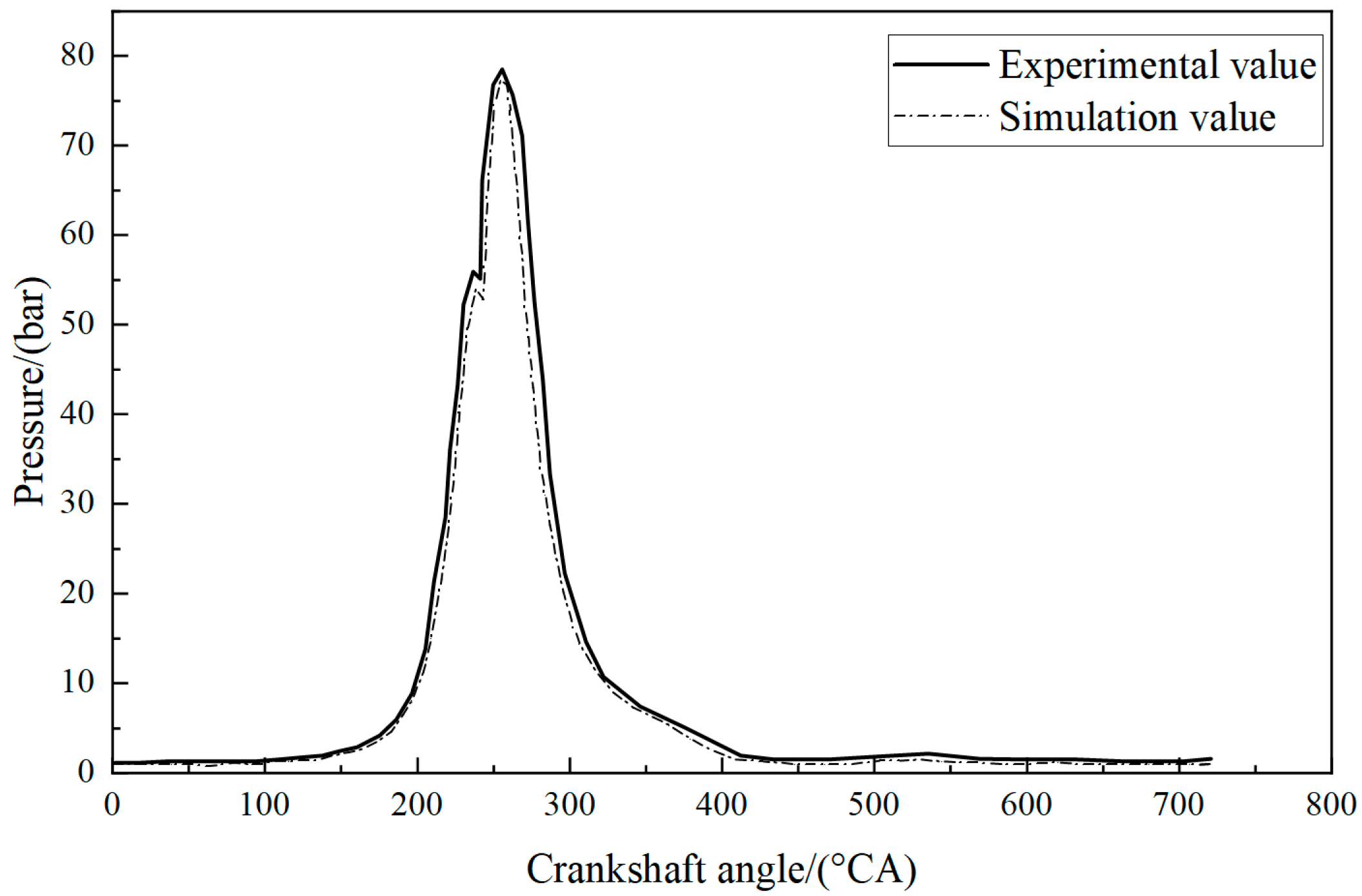
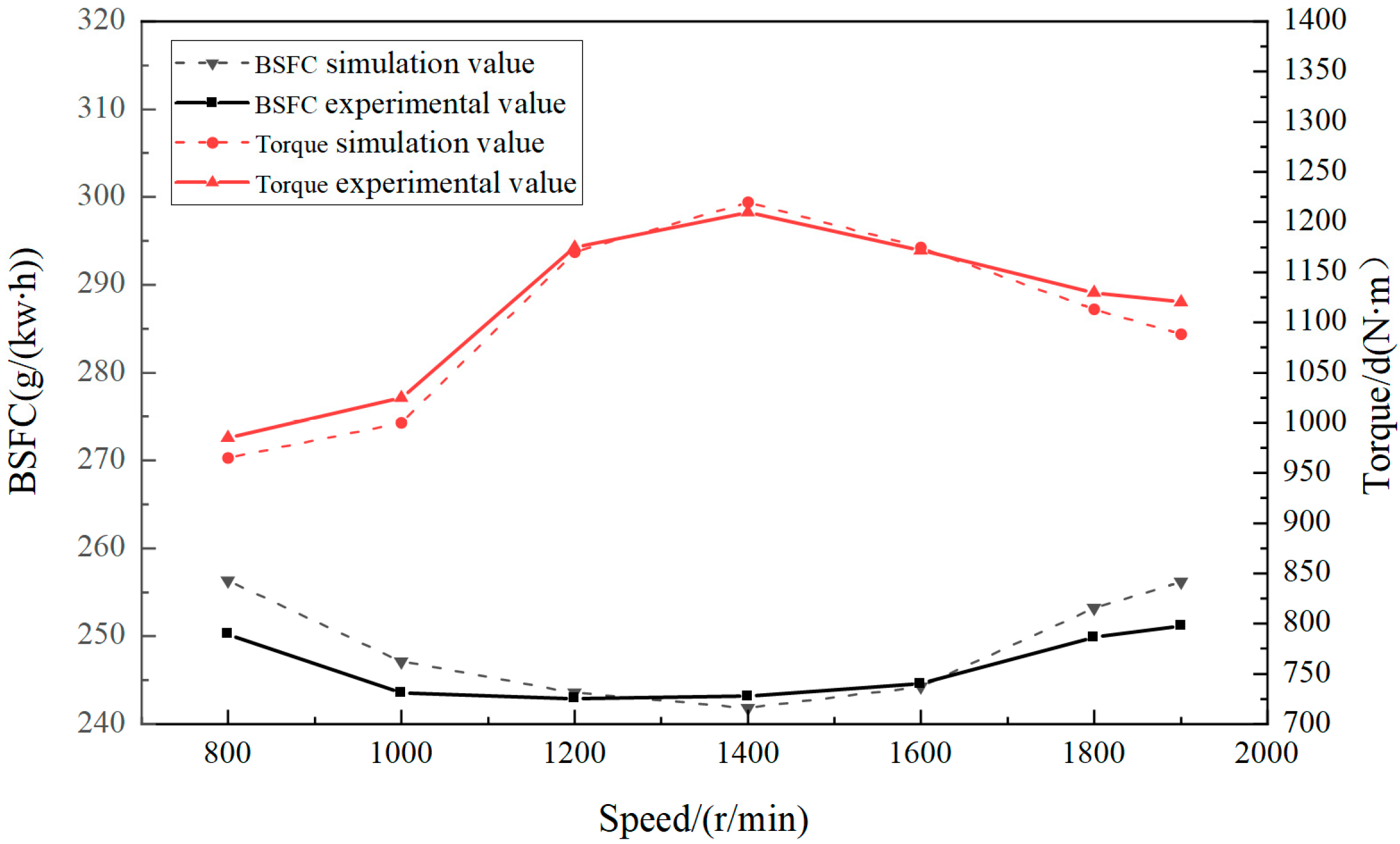
3.1. Model Development and Validation

This study utilized the engine simulation software AVL-BOOST to establish a model of a specific type of diesel engine. The key parameters required are shown in Table 1.
The engine model in this study employed the Wiebe function to characterize the combustion heat release curve. The accuracy of the Wiebe function was validated through a comparative analysis with the actual heat release rate curves, demonstrating satisfactory agreement prior to its implementation. Similar validation procedures were applied to the selection of fundamental heat transfer equations and friction loss models. Furthermore, the operational parameters, including temperature and pressure distributions across various engine components, were configured based on actual engine data. The final parameter calibration was performed through iterative adjustments to ensure consistency with the original engine specifications.
To conduct a more precise simulation study, it is essential to calibrate and validate the simulation model. The calibration process primarily involves fine-tuning fundamental parameters such as the combustion model, heat transfer model, and injection timing. This adjustment ensures that the simulation indicators align with the actual measurements within a reasonable range. The peak pressure values and their occurrence times measured during experiments, along with external characteristic indicators, serve as benchmarking references for the calibration model. By continuously refining the parameters of each module, the simulation results and actual results are compared, as illustrated in the figures.
Under rated operating conditions, the cylinder pressure curves obtained from simulation and experimentation are shown in Figure 3. The two sets of data were largely consistent; however, in the later stages of the power stroke, the simulated values were slightly lower than the experimental values. The maximum single-point error was 8.89%, while the overall average error was 4.37%. The simulation errors mainly stem from the unaccounted effects of air filtration resistance and pipe bend pressure losses.
Figure 4 presents the external characteristic curves, which illustrate how the performance indicators of the engine at full load vary with engine speed. The maximum single-point error for the simulated torque compared with the experimental value was 4.13%, with an overall average error of 3.22%. For the brake-specific fuel consumption, the maximum single-point error was 5.32%, and the overall average error was 4.1%. Overall, the results showed good agreement.

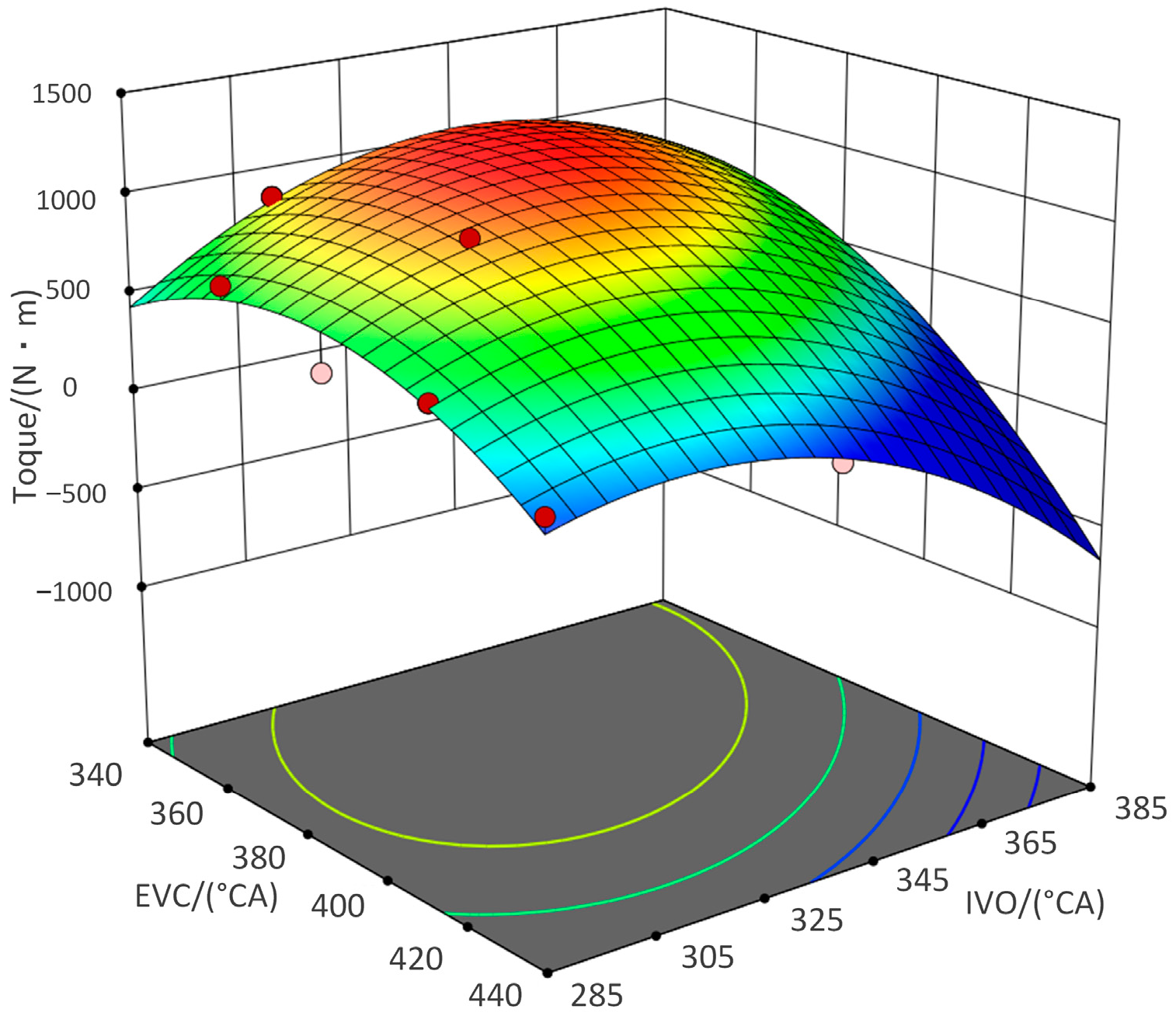
3.2. Effects of Variable Valve Parameters on Engine Performance

The use of a composite electromagnetic valve mechanism allows for continuous variable adjustment of the valve lift curve across all operating conditions. The entire valve lift curve can be determined by six factors: the timing of the opening and closing of both the intake and exhaust valves, as well as their maximum lift. Each of these factors will be analyzed individually.
Taking 1400 RPM at full load as an example, the Exhaust Valve Opening (EVO) timing was set as a variable. The original EVO data of the engine were used as the initial value, with an adjustment range of ±50° CA, in increments of 5° CA. This simulation analyzed the impact of EVO on torque under different stroke conditions in both single and dual drive modes of the composite electromagnetic valve mechanism. The results are shown in Figure 5.
The engine torque exhibited a trend of first decreasing, then increasing, and subsequently decreasing again with the advance and delay of EVO. If the exhaust valve opens too early, it results in reduced expansion work, while a delayed opening leads to increased blow-down losses, both of which cause a decline in torque. Under this operating condition, the optimal EVO timing was around 140° CA, which is relatively more delayed than the camshaft timing. This is attributed to the rapid response characteristics of the electromagnetic valve mechanism. Moreover, whether in single or dual drive mode, and for maximum strokes of 8 mm or 10 mm, the impact on torque was not significant. This indicates that, under this operating condition, an 8 mm maximum valve lift is sufficient to meet the exhaust requirements and achieve a “saturated state”, meaning that larger valve lifts do not yield substantial benefits. Therefore, considering the engine performance, the drive force requirements of the electromagnetic valve mechanism, and the energy consumption of the system, a relatively smaller valve lift in dual drive mode can be selected.
Similarly, an analysis was conducted on the effects of Intake Valve Closing (IVC), Exhaust Valve Closing (EVC), and Intake Valve Opening (IVO) timings based on the composite electromagnetic valve mechanism on torque. The results are presented in Figure 6 and Figure 7. Since EVC and IVO are related to the magnitude of the valve overlap, it is necessary to analyze their interaction and its impact on the engine performance.
The engine torque exhibits an increasing trend followed by a decrease with the advance and delay of IVC timing. If the intake valve closes too early, it results in insufficient intake, while a delayed closure can cause the backflow of gases within the cylinder, both of which lead to a reduction in torque. Similarly, due to the rapid response characteristics of the electromagnetic valve mechanism, the optimal IVC timing in this operating condition occurred earlier than that for the camshaft timing, around 530° CA. Furthermore, the differences between the single and dual drive modes and the maximum valve lifts of 8 mm and 10 mm had a negligible impact on torque. Since the gas pressure acting on the intake valve during opening is not significant, the drive force requirements are low. Therefore, a relatively lower valve lift in the single drive mode can be selected.
An appropriate valve overlap angle can facilitate a smoother intake and enhance exhaust efficiency. As shown in Figure 7, if the valve overlap angle is too large, it can lead to the backflow of exhaust gases; conversely, if the overlap angle is too small, it can result in an inadequate intake and hindered exhaust. Both scenarios negatively affect the engine’s intake efficiency and combustion quality, leading to performance degradation. Therefore, it is necessary to conduct a coordinated optimization of the valve timing parameters based on the engine operating conditions.

4. Multi-Objective Optimization of Fully Variable Valve Parameters

4.1. Establishment of the Optimization Model

The optimization variables are defined as the opening and closing timings of the intake (IVO and IVC) and exhaust (EVO and EVC) valves, along with the valve lifts for both. These variables are designated as x1, x2, x3, x4, x5, and x6, respectively.
The optimization objectives for the engine were to achieve the best performance in terms of power, fuel economy, and emission characteristics. Specifically, this entails maximizing the torque (under full-load conditions) or minimizing the brake-specific fuel consumption (BSFC) (under part-load conditions), while also ensuring the lowest possible NOx emissions. This can be expressed as follows:
M i n 1 / T o r q u e B S F C N O x s . t . 120 x 1 140 325 x 2 345 365 x 3 385 530 x 4 550 6 x 5 10 6 x 6 10
In the optimization process, based on the prototype camshaft’s valve timing, a single-parameter sweep method was initially employed to identify the preliminary optimized timing values. The investigation scope was set as ±10° CA around these baseline values. Considering the operational characteristics of the electromagnetic valve train system, the maximum achievable valve lift was determined to be 10 mm. The engine performance analysis revealed significant deterioration in key performance indicators when the valve lift fell below 6 mm. Consequently, the parameter variation range was established as 6–10 mm for the subsequent optimization studies.
To address the multi-objective optimization problem with common characteristics, it is necessary to employ suitable optimization strategies. Currently, the mainstream algorithms include genetic algorithms, particle swarm optimization, and simulated annealing, among others. Among these, the Non-dominated Sorting Genetic Algorithm II (NSGA-II) [26] employs probabilistic optimization while automatically obtaining optimal results and providing feedback to guide the search space for optimization objectives. This adaptive approach continuously adjusts the direction of the optimization search, demonstrating strong global optimization capabilities and parallel characteristics. It performs well in handling complex multi-objective problems. The Hybrid Steady-State Genetic Algorithm (HYBRID) [27] integrates the steady-state genetic algorithm with the Sequential Quadratic Programming (SQP) optimizer. The SQP algorithm not only refines the locally optimal designs identified by the genetic algorithm but also facilitates cooperation and information exchange between the two algorithms throughout the entire process. This approach is suitable for solving both single-objective and multi-objective problems. The MOGT algorithm [28] is based on competitive game theory among players, assigning each optimization objective to a player. By adjusting the values of the input variables assigned to them, the algorithm continuously updates the optimization targets. This approach is particularly effective in addressing highly constrained and nonlinear problems.
The three optimization algorithms mentioned above are all applicable to the multi-objective optimization of fully variable valve timing parameters discussed in this study. Taking the example of 1900 RPM at full-load conditions, we compared the convergence speeds of each algorithm under the same number of independent variables, their ranges, and optimization objectives. The results are shown in Figure 8.
From the optimization results, the maximum torque achievable by the three algorithms showed minimal variation. However, in terms of convergence speed, the MOGT algorithm reached convergence in approximately 700 iterations, while the NSGA-II and HYBRID algorithms required 1500 to 2000 iterations to converge. Therefore, this study employed the MOGT algorithm for simulation optimization.
The operating conditions defined in this study encompassed both the common operating conditions of a specific type of diesel engine and extreme conditions that facilitate subsequent research on the correlation between valve timing parameters and engine performance parameters. The speed range was set from 800 to 1900 RPM, with a simulation node taken every 200 RPM. For each speed range, four load levels were established: 17%, 45%, 72%, and 100%, with load variations achieved through adjustments in fuel injection quantity. The optimization workflow is illustrated in Figure 9.
In the MOGT algorithm settings, the maximum number of iterations for a single run was set to 100, with a maximum of 8 iterations for the simplex method. The final termination precision was set to 0.001, and the DOE perturbation factor was also 0.001. The variable selection method employed was smooth spline variance analysis. The computational results obtained through the software were filtered to meet the constraint conditions, and a scatter plot was generated, as shown in Figure 10.
Under full-load conditions, priority was given to the engine’s performance while also considering the nitrogen oxide emissions. From the scatter plot, it is evident that as the torque increased, the corresponding unit power consumption of nitrogen oxide emissions also rose, indicating a trade-off between the two factors. A curve can be observed along the outermost points of the dataset, which is typically referred to as the Pareto front in the optimization process [29]. When the torque of the engine was fixed on the horizontal axis, the Pareto front in the figure exhibited the minimum unit power consumption of nitrogen oxide emissions. Similarly, when the unit power consumption of nitrogen oxide emissions was fixed on the vertical axis, the Pareto front showed the maximum torque value. It is evident that the points on this curve represent the optimal solution set, from which the optimization results should be selected.

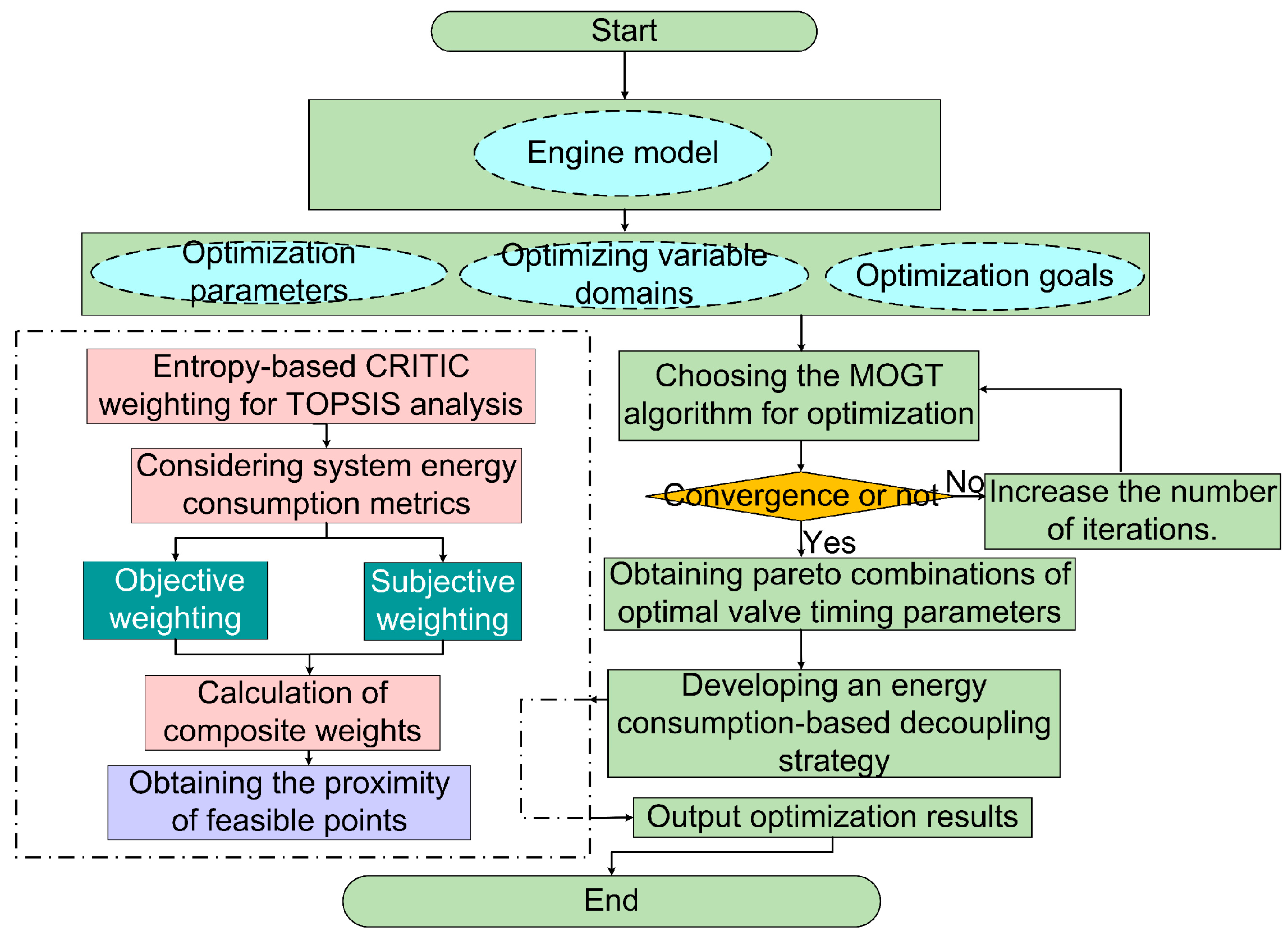
4.2. TOPSIS Analysis Based on Entropy-Based CRITIC Synthetic Weighting

The multi-objective optimization of the valve timing parameters resulted in a set of feasible solutions. An important issue is how to further consider the energy consumption of the electromagnetic valve mechanism when selecting the optimal solution from the Pareto front. In terms of evaluation methods, the entropy-based CRITIC method can avoid biased weighting and assessment results in site selection problems. TOPSIS, as a method for evaluating alternative solutions, is often used in conjunction with the entropy-based CRITIC weighting method in various evaluation analyses [30]. Therefore, this study employed the entropy-based CRITIC synthetic weighting method to assign weights to performance parameters of the engine, taking into account the varying levels of focus under different operating conditions. Using the obtained weights, an evaluation system was constructed, and the TOPSIS method was subsequently applied to assess the alternatives and determine suitable valve timing parameter combinations. The specific process is as follows:
1.
Construct the initial matrix.
Ten points are selected from the Pareto front shown in Figure 10 as ten alternatives for multi-objective decision analysis. There are three decision objective functions, represented as X = (xij) (i =1, 2…, 10; j = 1, 2, 3).
The initial evaluation matrix is as follows:
X = x 11 x 12 x 13 xn 1 x n 2 x n 3
Here, n represents the number of evaluation alternatives, n = 10.
2.
Normalize the matrix.
Since there are differences in the magnitude of the values for torque, effective fuel consumption rate, and unit power consumption of nitrogen oxide emissions, normalization is necessary. The torque is a positive indicator, where a larger value indicates better performance, while both the effective fuel consumption rate and the unit power consumption of nitrogen oxide emissions are negative indicators, meaning that smaller values indicate better performance. Therefore, they require different normalization treatments.
rij = xij xmin xmax xmin
rij = xmax xij xmax xmin
Formula (4) is the positive indicator and (5) is the negative indicator.
3.
The processed matrix is as follows:
Y = y 11 y 12 y 13 y n 1 y n 2 y n 3
4.
Calculate the weights using the entropy method.
First, calculate the proportion Pij for each alternative i under the indicator j. Then, using the proportions Pij, compute the entropy value ej for each indicator. Finally, the entropy method weights ω ej for each indicator are derived based on their entropy values ej. The specific calculation formulas are shown in Equations (7)–(9).
P ij = y i j i = 1 m y i j
e j = 1 ln   m i = 1 m p ij ln   p ij
ω ej = 1 e j j = 1 n ( 1 e j )
5.
Calculate the CRITIC weights.
Similar to the entropy method, the calculations for the CRITIC weights are also based on the normalized matrix Y. First, calculate the volatility Sj between the indicators, as shown in Equation (10), where the mean y ¯ j of the indicators is used. Then, compute the conflict Rj between the indicators, following the method outlined in Equation (11), where the correlation coefficient rij between indicators is calculated as described in Equation (12). Finally, the CRITIC weights ω ij for each indicator are derived using the volatility Sj and conflict Rj, as indicated in Equation (13).
S j = i = 1 m ( y i j y ¯ j ) 2 n 1
R j = i = 1 m ( 1 r i j )
r i j = j , k = 1 n ( y i j y ¯ j ) ( y i k y ¯ k ) j = 1 n ( y i j y ¯ j ) 2 k = 1 n ( y i k y ¯ k ) 2
ω cj = S j R j i = 1 m S j R j
6.
Calculation of objective weights.
The specific method is as follows:
ω ecj = ( ω e j + S j ) R j j = 1 m ( ω e j + S j ) R j
7.
Calculate the synthetic weights.
By surveying the specific requirements for engine performance under different operating conditions and excluding extreme cases, common data are used as the final weighting results. The weights for each performance indicator are denoted as ω sj . The synthetic weights ω j are then calculated using the following formula:
ω j = a ω e c j + b ω s j
8.
Construct the weighted decision matrix.
Based on the calculated weights ω j , establish the weighted matrix Z using the normalized matrix Y:
Z = ω j × y i j
9.
Determine the positive ideal solution (Z+) and the negative ideal solution (Z) for each indicator:
Z max = max z 11 , , z n 1 , max z 12 , , z n 2 , max z 13 , , z n 3 = Z 1 + , Z 2 + , Z 3 +
Z min = min z 11 , , z n 1 , min z 12 , , z n 2 , min z 13 , , z n 3 = Z 1 , Z 2 , Z 3
10.
Calculate the distance between each set of evaluation indicators and the positive ideal solution (Z+) and the negative ideal solution (Z):
V i + = ( i = 1 n ( z i j z j + ) 2
11.
Finally, calculate the closeness coefficient (Ri) for each set of evaluation indicators to the ideal solutions:
R i = V i V i + + V i
From the optimal valve timing parameter Pareto front, ten points were selected, with torque and unit power consumption of nitrogen oxides as the multi-objective decision factors. While ensuring engine performance, the energy consumption of the composite electromagnetic valve mechanism should also be considered, making energy consumption an additional multi-objective decision factor. The specific implementation involved obtaining the corresponding valve timing parameter data for the intake and exhaust valves at each selected point, calculating the valve duration and lift. Depending on the single or dual drive mode used at different points, the data were substituted into formula (1) to determine the energy consumption of the composite electromagnetic valve mechanism. The calculation results are presented in Table 2.
In the table, the intake valve operates in single drive mode, while the exhaust valve operates in dual drive mode. I denotes the maximum lift of the intake valve, and E denotes the maximum lift of the exhaust valve.
The closeness coefficient ranges from 0 to 1, with values closer to 1 indicating better overall performance. Combining the results from the table, the optimal point for the engine at 1900 RPM under full-load conditions is determined.
By repeating the above steps, the optimization results for the engine under all operating conditions can be obtained, leading to the establishment of a comprehensive control map for fully variable valve timing parameters.

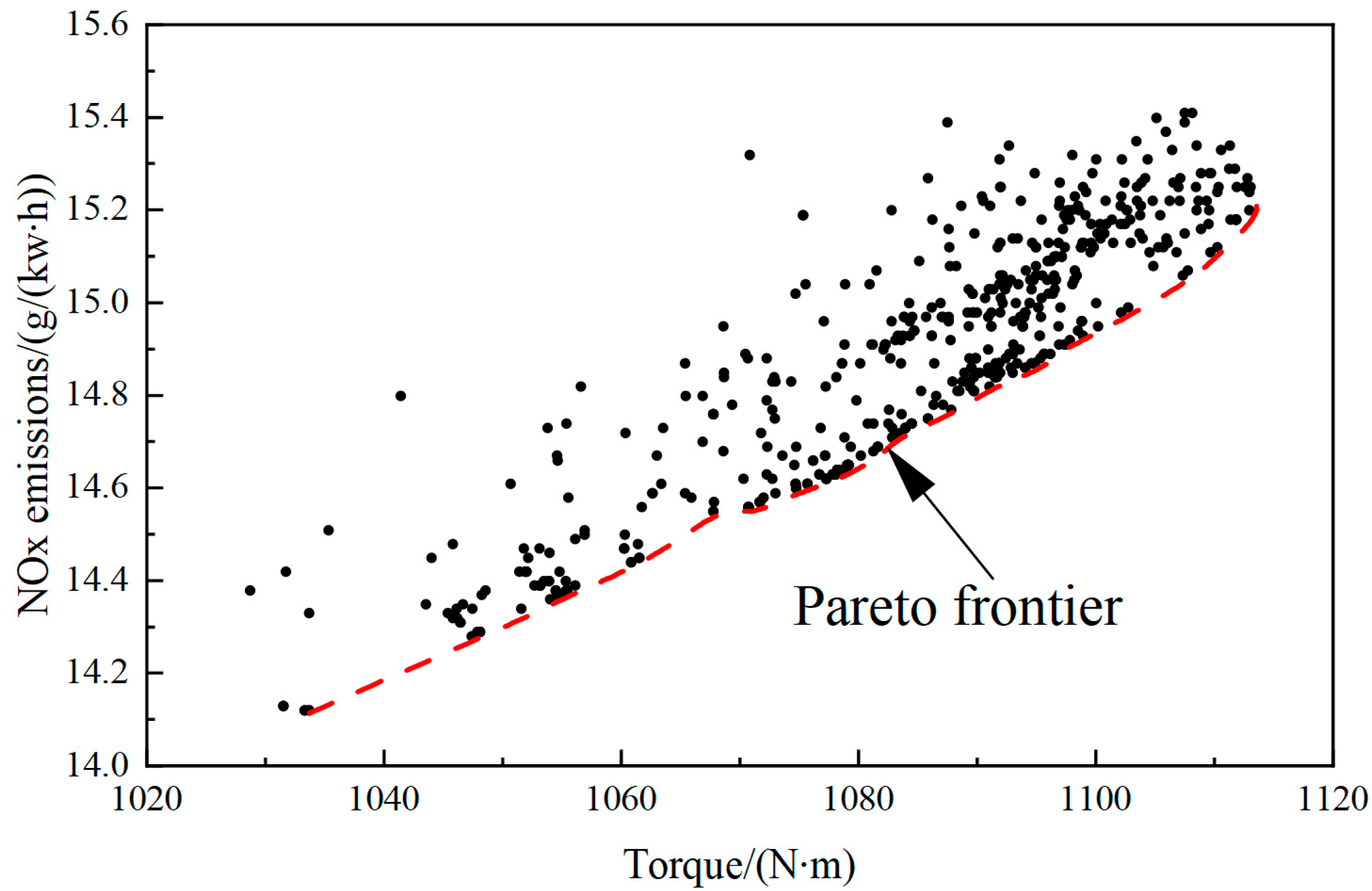
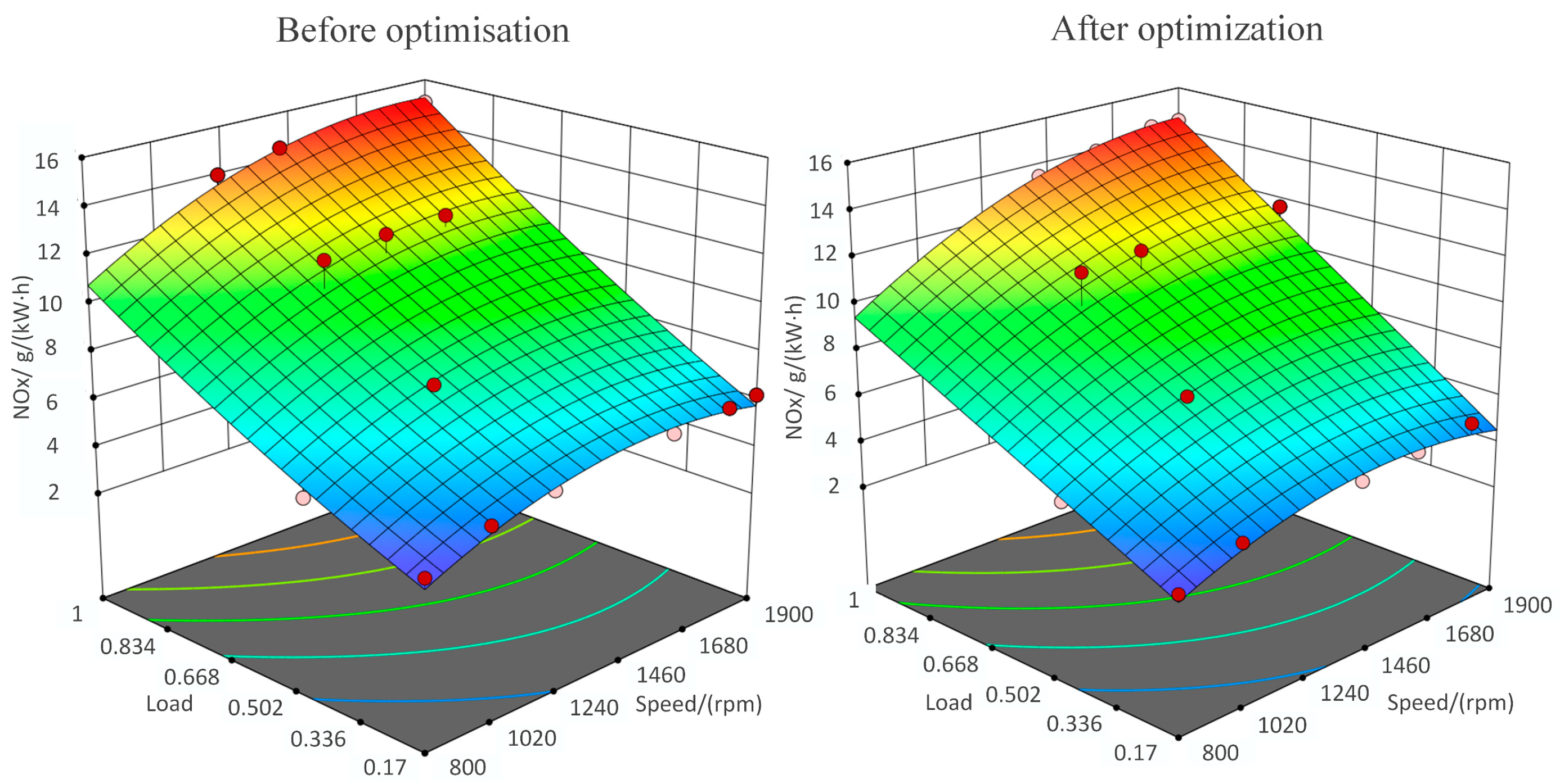
4.3. Analysis of Optimization Results

As shown in Figure 11, the optimized torque slightly increased, with a slight expansion in the high-torque region. On average, the torque improved by 2.56% across all the operating conditions.
In comparison with torque, the improvement in engine efficiency was more pronounced, showing significant enhancement. Through optimization, the areas enclosed by the contour lines of the equal effective fuel consumption rate were larger than those of the original engine. Furthermore, the original engine had zero area in which the effective fuel consumption rate was below 220 g/(kW∙h). Calculations showed that the optimized effective fuel consumption rate had an average reduction of 4.30% compared with the original value. Notably, under mid- to low-load conditions, the reduction in the effective fuel consumption rate can reach up to 6.23%. This improvement is attributed to the optimization of scavenging efficiency through variable valve timing technology.
As shown in Figure 12, the original simulation-calibrated NOx emissions exhibited a clear increasing trend with rising speed and load. Across the entire operating range, NOx emissions showed a significant decrease, particularly under mid- to low-speed and low-load conditions. The optimized NOx emissions were especially favorable, with reductions exceeding 20% at several individual operating points, with an average decrease of 9.86%.
As shown in Figure 13, the energy consumption of the valve mechanism decreased across all the operating conditions as the load and speed decreased. This is because, at the same speed, a reduction in load leads to a decreased demand for the driving force of the valve mechanism, resulting in lower energy consumption. Similarly, at the same load, a reduction in speed reduces the demand for driving force. Additionally, the lower speed results in fewer opening and closing cycles for the intake and exhaust valves, further contributing to the decrease in energy consumption.
Furthermore, we established comprehensive maximum lift control strategies for both the intake and exhaust valves across the entire operational range, along with the corresponding energy consumption distribution. As illustrated in Figure 13, the boundary annotations of the colored regions represent the maximum lift configurations for the intake and exhaust valves. Specifically, the notation “I6E8” marked at the boundary of the red region indicates that within this operational zone, a maximum intake valve lift of 6 mm and a maximum exhaust valve lift of 8 mm were implemented. The superimposed black contour lines represent the iso-energy consumption distribution mapped onto the two-dimensional plane, with each line connecting points of equal energy consumption levels.

5. Conclusions

This paper is based on a novel composite electromagnetic valve mechanism that features a high power-to-weight ratio, fast response, and high precision, as well as a unique single/dual drive mode. By analyzing the impact of different valve timing parameters and drive modes on the engine performance and developing optimization strategies for the valve timing parameters, the following conclusions can be drawn regarding the improvements in engine emissions, performance, and valve mechanism drive efficiency:
(1)
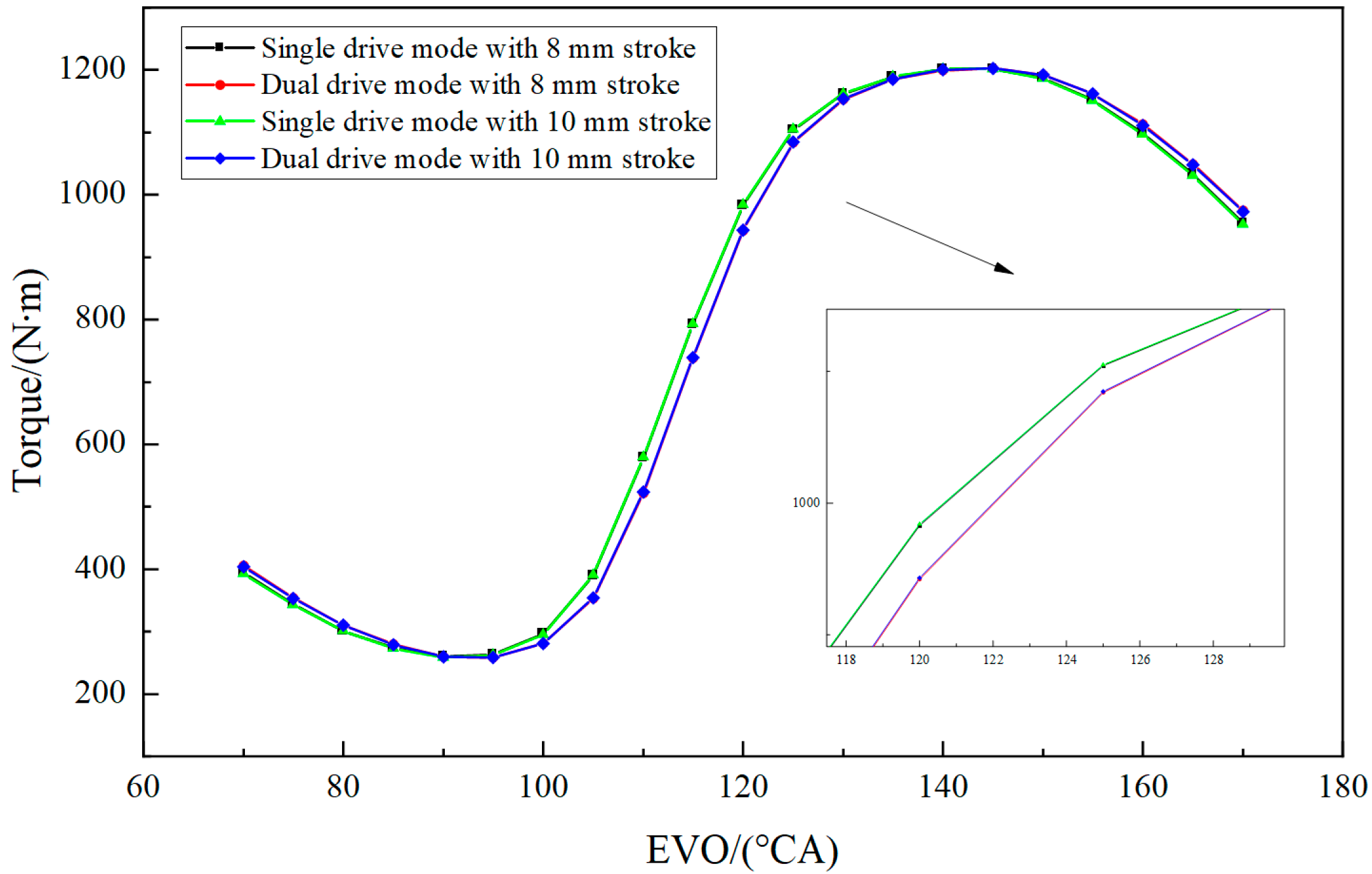
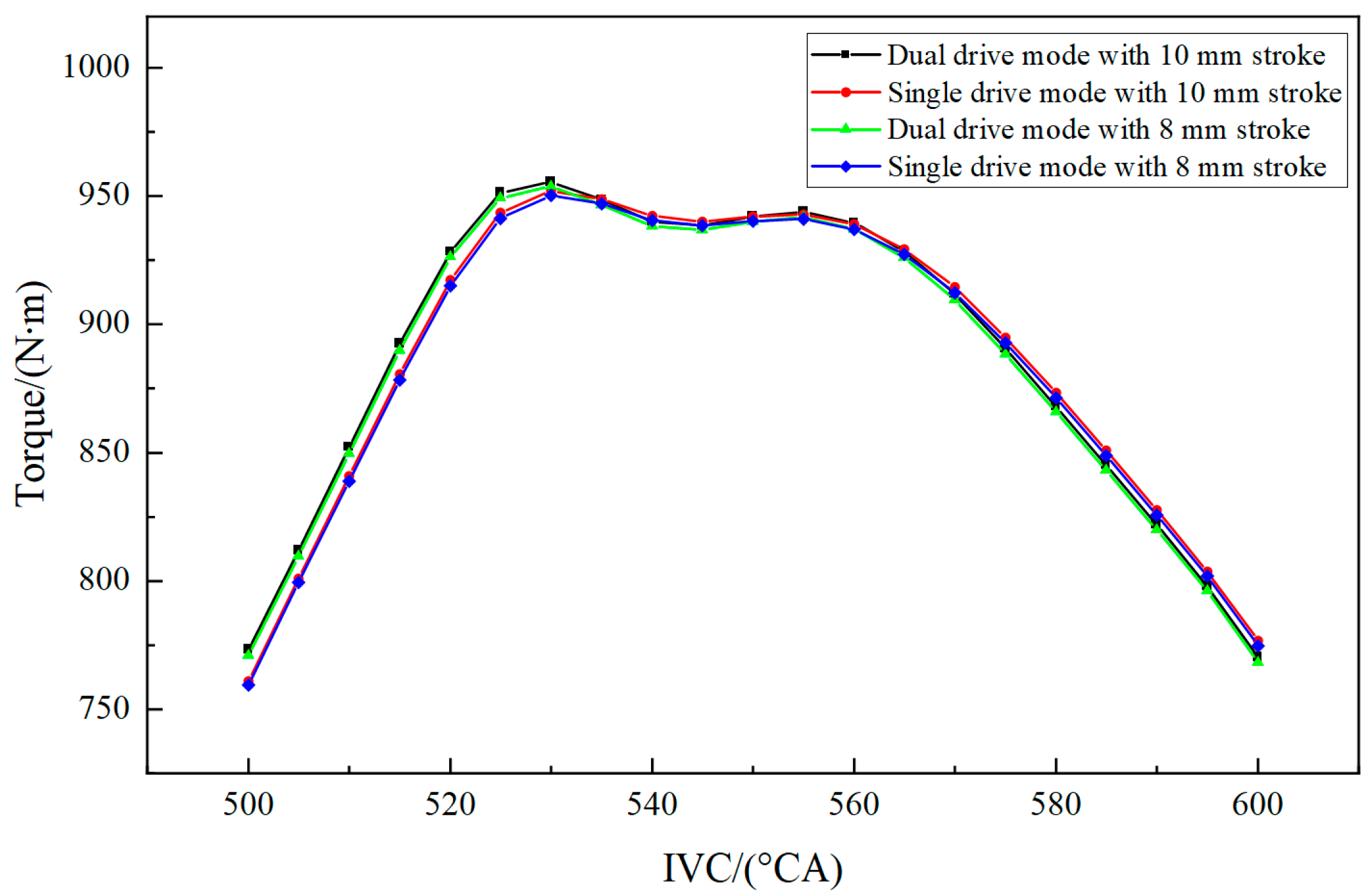
The fast response characteristics of the electromagnetic valve result in a delayed optimal exhaust opening timing and an earlier intake closing timing. While a larger valve lift (10 mm) does not lead to significant improvements in engine performance, it can increase the energy consumption of the valve mechanism. This is a key factor that needs to be considered during the optimization design of valve timing parameters.
(2)
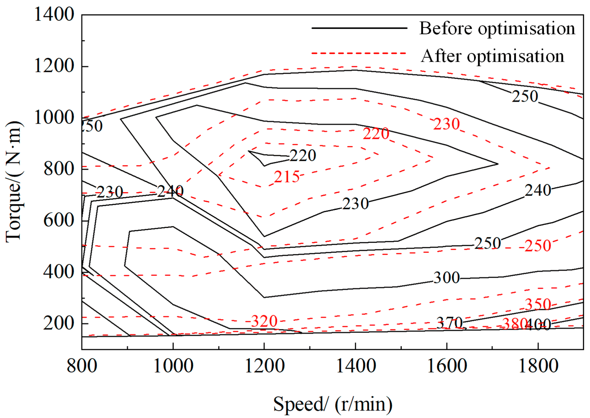
The use of a multi-objective game theory optimization algorithm for valve timing parameter optimization offers higher computational efficiency and accuracy. The results indicated an average torque increase of 2.56% across all operating conditions, a 6.23% reduction in effective fuel consumption, and a 9.86% decrease in nitrogen oxide emissions.
(3)
By incorporating the energy consumption and drive efficiency of the valve mechanism as decision factors, a valve timing control strategy was developed using the distance analysis method based on entropy-based synthetic weighting. This approach enabled the generation of an optimal valve operation mode MAP, effectively enhancing the drive efficiency of the composite electromagnetic valve mechanism while ensuring optimal engine performance.

Author Contributions

X.F.: conceptualization, funding acquisition, methodology, project administration, supervision, review and editing. L.Z. and J.Y.: experiment—review and editing. J.H. and W.S.: investigation and methodology. All authors have read and agreed to the published version of the manuscript.

Funding

This work was supported by the National Natural Science Foundation of China [grant number 52205271] and the Innovation team project of “Qing-Chuang science and technology plan” of colleges and universities in Shandong Province, China [2022KJ232].

Data Availability Statement

The raw data supporting the conclusions of this article will be made available by the authors on request.

Conflicts of Interest

The authors declared no potential conflicts of interest with respect to the research, authorship, and/or publication of this article.

Abbreviations

The following abbreviations are used in this manuscript:
ICEInternal combustion engine
MOGTMulti-objective game theory
CRITICCriteria Importance Though Intercriteria Correlation
TOPSISTechnique for Order Preference by Similarity to an Ideal Solution
EVOExhaust Valve Opening
BSFCBrake-specific fuel consumption
IVCIntake Valve Closing
EVCExhaust Valve Closing
TVOIntake Valve Opening
CACrank angle

References

  1. Fang, S.; Zhang, R.; Maltsev, S.; Chen, D.; Fan, X.; Levtsev, A. A novel adaptive fast sliding mode control method based on fuzzy algorithm for the air management system of fuel cell stack. Process Saf. Environ. Prot. 2024, 187, 506–517. [Google Scholar] [CrossRef]
  2. Hu, D.; Gao, P.; Cheng, Z.; Shen, Y.; He, R.; Yi, F.; Lu, M.; Wang, J.; Liu, S. Comprehensive review of hydrogen leakage in relation to fuel cell vehicles and hydrogen refueling stations: Status, challenges, and future prospects. Energy Fuels 2024, 38, 4803–4835. [Google Scholar] [CrossRef]
  3. Li, Y.; Ru, X.; Yang, M.; Zheng, Y.; Yin, S.; Hong, C.; Peng, F.; Qu, M.; Xue, C.; Lu, J.; et al. Flexible silicon solar cells with high power-to-weight ratios. Nature 2024, 626, 105–110. [Google Scholar] [CrossRef] [PubMed]
  4. Toader, V.E.; Milici, L.D.; Ungureanu, C.; Bejenar, C.; Vasilica, O. Grosu Analysis of a Low-Speed Drive System Using Intelligent Materials. Actuators 2021, 11, 10. [Google Scholar] [CrossRef]
  5. Shan, B.; Ai, T.; Wang, K. Triboelectric Nanogenerator for Ocean Energy harvesting: A review of technological advances and future perspectives. Int. J. Electrochem. Sci. 2024, 19, 100694. [Google Scholar] [CrossRef]
  6. Ahn, S.; Neary, V.S. Investigation of mixed long-term nonstationary trends in global wave energy systems. J. Clean. Prod. 2024, 476, 143758. [Google Scholar] [CrossRef]
  7. Jiang, F.; Yuan, X.; Hu, L.; Xie, G.; Zhang, Z.; Li, X.; Hu, J.; Wang, C.; Wang, H. A comprehensive review of energy storage technology development and application for pure electric vehicles. J. Energy Storage 2024, 86, 111159. [Google Scholar] [CrossRef]
  8. Zhou, Z.; Zhang, G.; Chen, M. A Fault-Tolerant Control Strategy for Distributed Drive Electric Vehicles Based on Model Reference Adaptive Control. Actuators 2024, 13, 486. [Google Scholar] [CrossRef]
  9. Lešnik, L.; Kegl, B.; Torres-Jiménez, E.; Crue-Peragón, F. Why we should invest further in the development of internal combustion engines for road applications. Oil Gas Sci. Technol. Rev. D’ifp Energ. Nouv. 2020, 75, 56. [Google Scholar] [CrossRef]
  10. Wu, B.; Shi, M.; Zi, Z.; Jin, S. Influence of cooling loss on the energy and exergy distribution of heavy-duty diesel engines based on two-stage variable supercharging, VVT, and EGR. Int. J. Engine Res. 2024, 25, 896–910. [Google Scholar] [CrossRef]
  11. Han, Z.; Hu, M.; Zhao, J.; Yu, W. Study on the influences of oil supply pressure and maximum opening of electromagnetic valve on upstream pressure fluctuation. Int. J. Engine Res. 2021, 22, 935–948. [Google Scholar] [CrossRef]
  12. Tripathy, S.; Das, A.; Sahu, B.; Srivastava, D.K. Electro-pneumatic variable valve actuation system for camless engine: Part I-development and characterization. Energy 2020, 193, 116740. [Google Scholar] [CrossRef]
  13. Fan, X.; Dai, J.; Lu, J.; Xu, H.; Tan, C. Kinetic behavior evaluation of electromagnetic valve train subject to exhaust gas force. Appl. Therm. Eng. 2020, 171, 115097. [Google Scholar] [CrossRef]
  14. Tan, C.; Chang, S.; Liu, L. Dynamic performance design and analysis of hybrid excited linear actuator for on-off valve. Int. J. Appl. Electromagn. Mech. 2017, 54, 199–209. [Google Scholar] [CrossRef]
  15. Tan, C.; Li, B.; Ge, W.; Sun, B. Design and analysis of a bi-stable linear force actuator for directly-driven metering pump. Smart Mater. Struct. 2018, 27, 107001. [Google Scholar] [CrossRef]
  16. Kuroda, J.; Majima, Y.; Ogawa, K.; Ikeda, K.; Kato, T.; Endo, A.; Narita, T.; Kato, H. Basic study on high precision positioning in electromagnetic valve drive system for improving internal combustion engine using linear actuator. Int. J. Appl. Electromagn. Mech. 2023, 71, S333–S341. [Google Scholar] [CrossRef]
  17. Xinyu, F.A.N.; Peng, W.A.N.G.; Jie, Y.I.N.; Yanbing, Z.H.U. Multi-mode Coordination Control of a Novel Compound Electromagnetic Linear Actuator. China Mech. Eng. 2023, 34, 292–299. [Google Scholar] [CrossRef]
  18. Jiang, K.; Zeng, H.; Wu, Z.; Sun, J.; Chen, C.; Han, B. Study on the Effect of Parameter Sensitivity on Engine Optimization Results. Energies 2023, 16, 7899. [Google Scholar] [CrossRef]
  19. Zhaohui, Z.; Lu, D.; You, T.; Xie, F. Research on Variable Displacement Valve Control Strategy Based on Electro-hydraulic Drive Intake and Exhaust Valve Opening and Closing Mode. Int. J. Automot. Technol. 2024, 25, 1445–1468. [Google Scholar] [CrossRef]
  20. Zhaohui, Z.; Hong, W.; You, T.; Su, Y.; Li, X.; Xie, F. Effect of Multi-Factor Coupling on the Movement Characteristics of the Hydraulic Variable Valve Actuation. Energies 2020, 13, 2870. [Google Scholar] [CrossRef]
  21. Zhang, E.; He, F.; Lu, Y.; Yang, X. Multi-body dynamics modeling and energy consumption optimization of electromagnetic mechanical fully variable valve system. Proc. Inst. Mech. Eng. Part C J. Mech. Eng. Sci. 2024, 238, 10952–10963. [Google Scholar] [CrossRef]
  22. Shao, D.; Sichuan, X.; Du, A. Research on a New Electromagnetic Valve Actuator Based on Voice Coil Motor for Automobile Engines; SAE Technical Paper 2017-01-1070; SAE: Warrendale, PA, USA, 2017. [Google Scholar] [CrossRef]
  23. Chang, S.; Liu, L.; Li, Z.; Xu, Z. Application of engine electromagnetic actuated valvetrain. J. Nanjing Univ. Sci. Technol. 2011, 35, 585–589. [Google Scholar] [CrossRef]
  24. Fan, X.; Zhu, Y. Collaborative optimization of multi-physical fields for composite electromagnetic linear actuators. Int. J. Appl. Electromagn. Mech. 2024, 76, 1–21. [Google Scholar] [CrossRef]
  25. Fan, X.; Xie, C.; Zhu, Z.; Li, Y. Loss analysis of a novel compound electromagnetic linear actuator under different operating modes and working conditions. Int. J. Appl. Electromagn. Mech. 2023, 72, 53–68. [Google Scholar] [CrossRef]
  26. Liu, Y.; Meng, J.; Li, T. Structural Optimization of a Giant Magnetostrictive Actuator Based on BP-NSGA-II Algorithm. Actuators 2024, 13, 293. [Google Scholar] [CrossRef]
  27. Knypiński, Ł.; Devarapalli, R.; Gillon, F. The hybrid algorithms in constrained optimization of the permanent magnet motors. IET Sci. Meas. Technol. 2024, 18, 613–619. [Google Scholar] [CrossRef]
  28. Yang, Z.; Guo, P.; Wang, L.; Hao, Q. Multi-objective optimization analysis of hydrogen internal combustion engine performance based on game theory. Appl. Energy 2024, 374, 123946. [Google Scholar] [CrossRef]
  29. Dosantos, P.S.; Bouchet, A.; Mariñas-Collado, I.; Montes, S. OPSBC: A method to sort Pareto-optimal sets of solutions in multi-objective problems. Expert Syst. Appl. 2024, 250, 123803. [Google Scholar] [CrossRef]
  30. Xu, C.; Ke, Y.; Li, Y.; Chu, H.; Wu, Y. Data-driven configuration optimization of an off-grid wind/PV/hydrogen system based on modified NSGA-II and CRITIC-TOPSIS. Energy Convers. Manag. 2020, 215, 112892. [Google Scholar] [CrossRef]
Figure 1. Physical image (left) and schematic diagram (right) of the composite electromagnetic valve mechanism.
Actuators 14 00168 g001
Figure 2. Performance test results of the mechanism under different strokes and durations in single/dual drive modes.
Actuators 14 00168 g002
Figure 3. Calibration results of in-cylinder pressure.
Actuators 14 00168 g003
Figure 4. Calibration results of torque and fuel consumption rate.
Actuators 14 00168 g004
Figure 5. Effect of EVO on torque for different strokes in single/dual drive mode.
Actuators 14 00168 g005
Figure 6. Effect of IVC on torque for different strokes in single/dual drive mode.
Actuators 14 00168 g006
Figure 7. Effect of valve overlap angle on torque.
Actuators 14 00168 g007
Figure 8. Comparison of optimization algorithms.
Actuators 14 00168 g008
Figure 9. Flowchart of the optimization model.
Actuators 14 00168 g009
Figure 10. Scatter plot of optimization calculation results under full-load condition at 1900 RPM.
Actuators 14 00168 g010
Figure 11. Comparison of engine characteristics before and after optimization.
Actuators 14 00168 g011
Figure 12. Unit nitrogen oxide emissions before (left) and after (right) optimization across all operating conditions.
Actuators 14 00168 g012
Figure 13. Energy consumption of the composite electromagnetic valve mechanism across all operating conditions.
Actuators 14 00168 g013
Table 1. Basic technical parameters of the engine model.
ProjectPerformance Indicators
Engine typeIn-line, water-cooled, four-stroke
Number of cylinders6
Displacement (L)12.419
Valves per cylinder4
Compression ratio (-)19:1
Bore (mm)126
Itinerary (mm)166
Firing order1-5-3-6-2-4
Rated speed (r/min)1900
Whether to boostNot
Table 2. Evaluation target decision results for diesel engine at 1900 RPM under full load.
Feasible PointsTorque/(N∙m)Energy Consumption of the Valve Mechanism/(kW)NOx Emissions/(g/(kW∙h))Closeness Level (Ri)
111133.94 (I10E10)15.25310.653
21110.193.94 (I10E10)15.11740.732
31107.713.94 (I10E10)15.07010.746
41104.833.00 (I10E8)15.07590.734
51101.452.85 (I8E8)15.13160.651
61098.873.94 (I10E10)14.92900.594
71097.423.00 (I10E8)14.91270.556
81096.823.00 (I10E8)14.94570.542
91094.783.79 (I8E10)14.87180.498
101090.982.85 (I8E8)14.81670.483
Disclaimer/Publisher’s Note: The statements, opinions and data contained in all publications are solely those of the individual author(s) and contributor(s) and not of MDPI and/or the editor(s). MDPI and/or the editor(s) disclaim responsibility for any injury to people or property resulting from any ideas, methods, instructions or products referred to in the content.

