Article

Development of Tendon-Driven Continuum Robot with Visual Posture Sensing for Object Grasping

1
Department of Pure and Applied Physics, Waseda University, Tokyo 169-8555, Japan
2
Faculty of Science and Engineering, Waseda University, Tokyo 169-8555, Japan
*
Author to whom correspondence should be addressed.
Actuators 2025, 14(3), 140; https://doi.org/10.3390/act14030140
Submission received: 1 December 2024 / Revised: 8 March 2025 / Accepted: 11 March 2025 / Published: 13 March 2025
(This article belongs to the Special Issue Advanced Mechanism Design and Sensing for Soft Robotics)

Abstract

:
Inspired by the characteristics of living organisms with soft bodies and flexibility, continuum robots, which bend their robotic bodies and adapt to different shapes, have been widely introduced. Such robots can be used as manipulators to handle objects by wrapping themselves around them, and they are expected to have high grasping performance. However, their infinite degrees of freedom and soft structure make modeling and controlling difficult. In this study, we develop a tendon-driven continuum robot system with color-based posture sensing. The robot is driven by dividing the continuum body into two parts, enabling it to grasp objects by flexible motions. For posture sensing, each joint is painted in a different color, and the 3D coordinates of each joint are detected by a stereo camera for estimating the 3D shape of the robotic body. By taking a video of the robot in actuation and using image processing to detect joint positions, we succeeded in obtaining the posture of the entire robot in experiments. We also robustly demonstrate the grasping manipulation of an object using the redundant structure of the continuum body.

1. Introduction

Continuum robots are designed to structurally mimic the dexterity and adaptability of animals, such as elephants’ trunks [1,2], an ostrich [3], and tentacles [4]. These robots have been the focus of many studies due to their inherent compliance, dexterity, and operational safety [5], and are expected to be applied in unstructured environments, such as searching in collapsed buildings [6], nuclear reactor maintenance [7], and minimally invasive surgery [8,9].
This mechanism can be used as a manipulator with high grasping capability [10]. Continuum robots can grasp objects with their entire arm, called “whole arm grasping” [11]. Compared to conventional end-effector grasping, whole-arm grasping distributes the contact points between the robot and the object, thus reducing the actuation force and improving the ability to manipulate heavy objects [12]. Furthermore, since there are no restrictions due to the end-effectors, objects of various sizes can be manipulated without causing breakage or damage [11,13].
However, due to the infinite degrees of freedom and their soft bodies, continuum robot modeling and control are very difficult [14,15,16]. Control methods using machine learning have been proposed to address this problem [15,17,18,19]. Current research focuses on the target reachability of the end effectors, but the tasks of overall robot posture control and object grasping have not been addressed.
Our goal is to develop a system that can recognize objects and autonomously grasp and manipulate them according to their shape and size. In our previous work [20], we developed a tendon-driven continuum robot manipulator with ball joints. Ball joints have the advantages of unlimited directions of movement with proper rigidity under passive operation and are efficiently fabricated with a simple structure. We demonstrated its multi-directional operability and grasping capability. There was a problem, however, where the posture of the object to be grasped was limited. Therefore, in this study, a two-part driven structure is introduced to enable a higher degree of freedom of motion and to enhance grasping ability. In driving a continuum robot, there are many advantages to dividing the entire robot into multi-sections. First, the increased freedom of movement of the robot allows it to assume a greater variety of postures and to flexibly adapt and deform according to its environment. For example, in complex tasks such as obstacle avoidance, the robot can move skillfully in response to a situation [21,22]. This greatly expands the potential for applications in situations where interaction with the environment is required. There are also significant advantages in object grasping; by driving each section independently, the robot can adapt its grasping to the posture and shape of the object through twisting movements, which is expected to improve grasping performance [5].
Focusing on the above issues, we have developed a tendon-driven continuum robot, which can be operated by dividing the body into two sections, and we conducted experiments to verify the robot’s performance.
In order to flexibly grasp an object placed in an arbitrary posture, we introduce a 3D posture recognition system that uses a stereo camera for the purpose of recognizing a robot’s posture. Unlike conventional robots, continuum robots cannot directly acquire their shapes. Therefore, it is necessary to incorporate a mechanism to estimate a robot’s posture [23]. The most used shape-sensing method is performed through the use of markers [24,25]. For the purpose of grasping an object, however, the presence of attached markers may interfere with the manipulation of an object, and occlusion may cause difficulty in achieving correct posture recognition. In this study, we introduce an image processing method by using the colored ball joints installed in the robot body and estimate the posture by tracking them. This method is expected to measure the posture robustly against occlusion without disturbing the interaction with objects. We succeed in acquiring the posture of the entire robotic body by visually tracking the robot in operation and letting the robot properly grasp an object placed in different postures.
We also confirm that the continuum body autonomously adjusts to the object’s shape for the wrapping articulation.

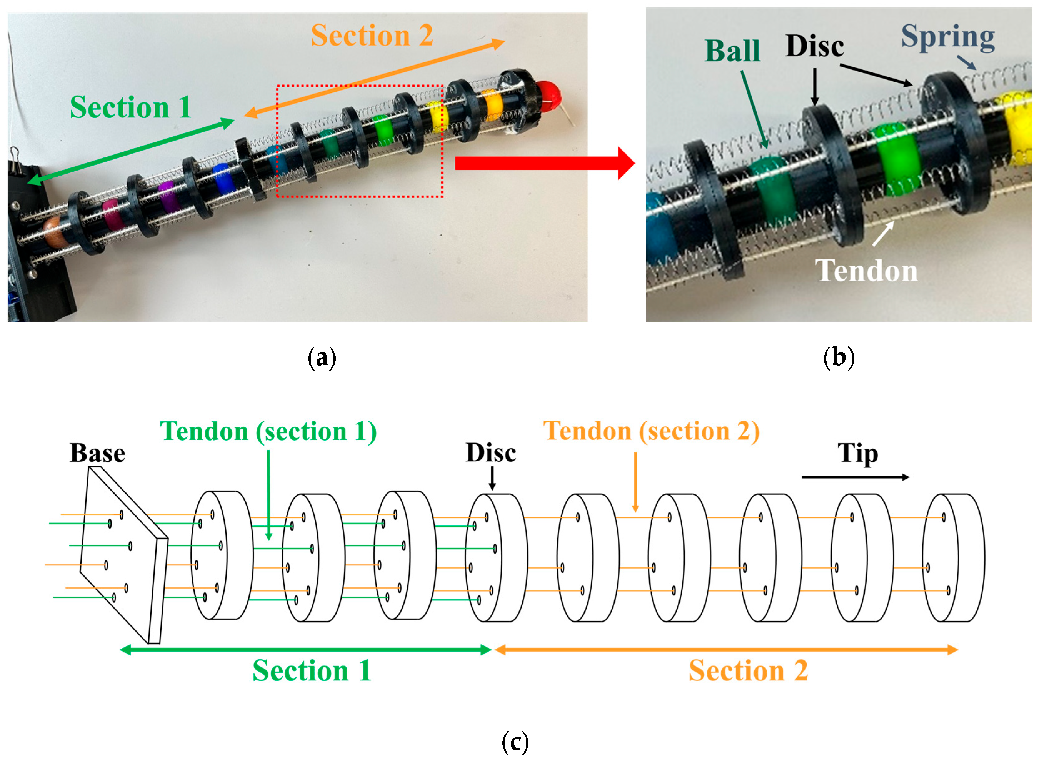
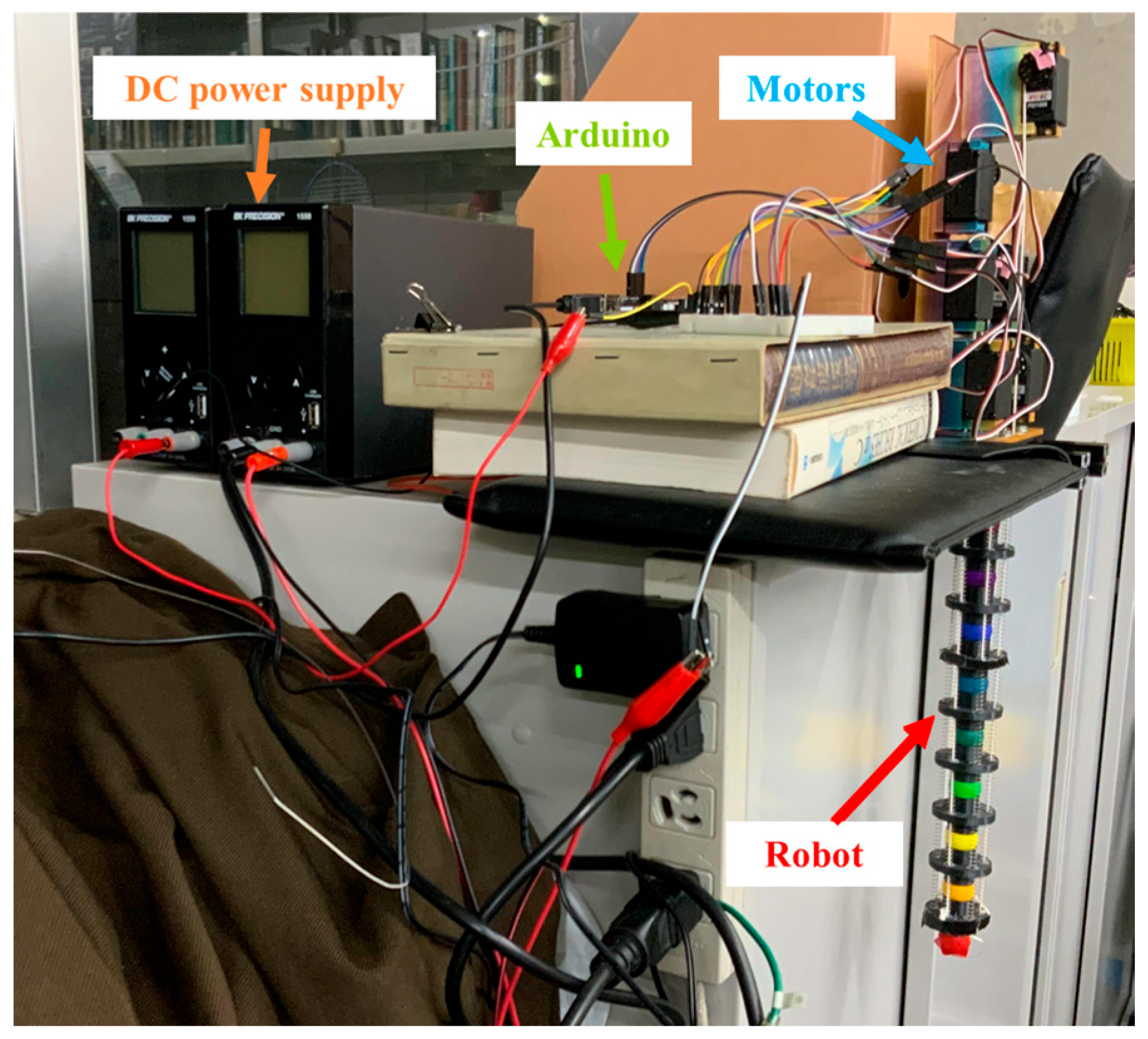
2. Design and Control of Robot
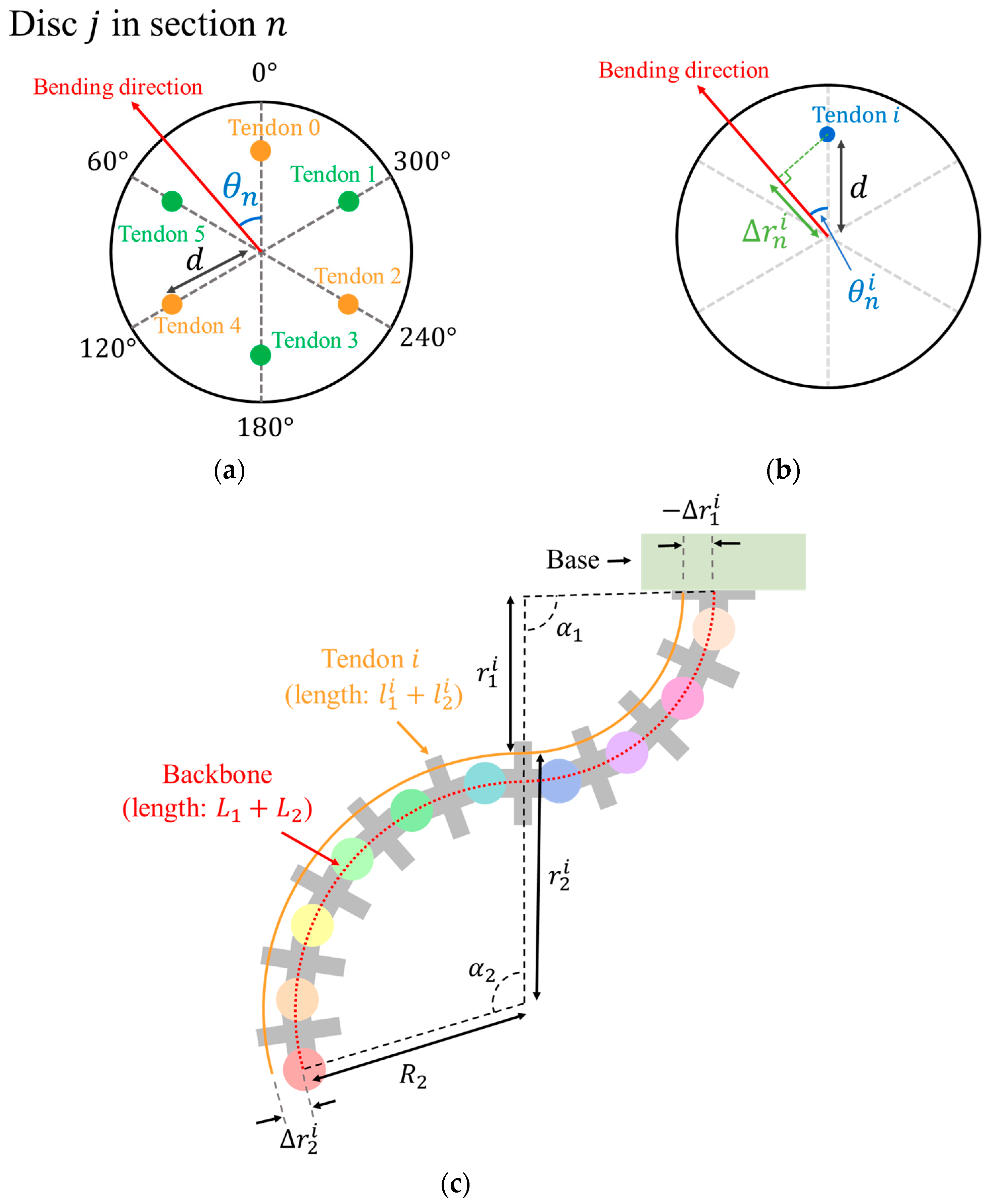
2.1. Design

In the previous study [20], we developed a tendon-driven continuum robot using ball joints, where eight discs and seven balls are connected alternately. In this study, we extend the robot structure to have ten balls and nine discs, as shown in Figure 1. As with our previously introduced robot, the balls are also made of wood, and the discs are fabricated by a 3D printer using PLA (Polylactic acid). The diameter of the ball is 20 mm, and the width of the exposed area of the ball, excluding the overlap with the discs on both sides, is 10 mm.
The robotic body is 340 mm long and 40 mm in diameter. As described in Figure 1a, the balls are painted in nine different colors (red, orange, yellow, lime, green, teal, blue, blue–violet, and purple) for posture sensing, except for the brown ball, which is directly connected to the base. Acrylic gouache (030812, Turner Colour Works Ltd., Osaka, Japan) was used for the painting.
The robotic body is divided into two sections for control. As illustrated in Figure 1c, this robot is controlled by dividing it into two sections. The base side is defined as section 1, and the tip side is section 2. Section 1 is from the base to the fourth disc, and section 2 is from the fourth disc to the tip of the continuum body.
Three tendons are equally spaced per section, for a total of six. One end of each tendon is connected to a rotation servo motor (FS5106R, Shenzhen Feetech RC Model Co., Ltd., Shenzhen, Guangdong, China) for control, and the other end is connected to a disc (the tendon in section 1 to the fourth disc and the disc in section 2 to the tip disc).

2.2. Control

The basic control strategy is described in our previous paper [20]. By pulling the tendons using the motors settled in the base, the robot bends its body. Then, by releasing the pulling force, the robot returns to the initial state by the effect of the restorative force generated by the contracted spring. To get the robot to achieve the target posture, each section must be bent in the proper direction by sending a proper control command. Since the lengths of all tendons must be properly adjusted when bending in a particular direction, it is necessary to formulate a relationship between the direction of bending and the ratio of the change in length of each tendon. Therefore, in this study, this relationship is simply defined by assuming that each section bends with constant curvature in the bending action to an intended direction. Although this model is not accurate, we consider it sufficient to validate the robotic grasping performance.
As illustrated in Figure 2a, the tendons are numbered from 0 to 5, clockwise seen from the base. Tendons with odd numbers are for section 1, and tendons with even numbers are for section 2. In section n ( n = 1 ,   2 ), the bending direction θ n is defined based on the direction of tendon number 0. The angle between the bending direction and the direction of each tendon is described by the following equation.
θ n i = θ n + 60 ° × i
For each tendon, we define Δ r n i as shown in Figure 2b, which is related to the amount of change in the length of the tendon when the robot is moved to specific direction. Figure 2c shows the length of the backbone and tendons in a bent posture. To bend the section n in the direction of θ n i with a radius of curvature R n (central angle α n ), the length of tendon i should be varied as follows:
Δ l n i = l n i L n = α n r n i R n = α n Δ r n i = α n d cos θ n i
where d is the distance between the backbone and a tendon, which is 15 mm.
Equations (1) and (2) allow us to calculate how much the length of each tendon should be changed to bend the robotic body in a particular direction. In the robot, the employed servomotors are controlled by the rotation speed instead of the rotation angle. Therefore, by setting the rotation speed of each motor to be proportional to the value of cos θ n in Equation (2), the bending action in the specified direction can be properly achieved. Since the central angle of the arc α n is determined by the rotating time t n , the input to the corresponding motor can be obtained by converting θ n , α n , which represents the shape of each section in the above constant curvature model into ( θ n , t n ) . Thus, the robotic system takes four input parameters, which are the bending directions ( θ 1 , θ 2 ) and bending times ( t 1 , t 2 ) for each of the two sections. Therefore, the inputs to the robotic system can be represented as ( θ 1 , t 1 , θ 2 , t 2 ).
The robot’s control system determines the drive speed of each motor based on the bending direction θ 1 , θ 2 . Using Equations (1) and (2), the appropriate rotation speed for each motor is calculated. All motors are connected to an Arduino UNO, and control signals are sent from this microcontroller to each motor.
In basic operations that do not involve interaction with objects, section 1 is operated first to fix its posture, and then section 2 is driven. In object grasping tasks, on the other hand, section 1 and section 2 are moved in a special sequence. First, the bending time t 2 of section 2 is divided into two parts, and the first half of the operation is performed. Next, section 1 is driven for that bending time t 1 . Finally, the remaining movement of section 2 is performed.
In other words, in the task of object grasping, the movement of section 2 is divided into two parts, one before and one after the movement of section 1. This is because if section 1 is driven first with a movement that involves a large deformation, such as grasping an object, section 2 will not deform sufficiently due to gravity on section 2 and friction at the joints.
Therefore, the steps of robot control are described as follows:
  • Based on the bending direction θ 1 , θ 2 , calculate the appropriate rotation speed of each motor using Equations (1) and (2).
  • (In object grasping) rotate the motors in section 2 at the calculated rotation speed for 500 ms, and then stop the motor.
  • Rotate the motors in section 1 at the calculated rotational speed for the bending time t 1 and stop.
  • Rotate the motors in section 2 at the calculated rotation speed for the bending time t 2 ( t 2 -500 when object grasping task), and stop.
In this way, and based on the inputs ( θ 1 , t 1 , θ 2 , t 2 ), the Arduino UNO controls the motors to achieve the robot’s motion.

3. Construction of Visual Posture Sensing System

Since the body deformation of a continuum robot cannot be directly acquired, we introduce an image processing method for the estimation of the posture by tracking markers situated in the robotic body. Figure 3 shows the positions of the robot and the stereo camera in the posture sensing system of this study. The robot is fixed with its tip hanging down. The distance between the two cameras (C922n, Logicool, Tokyo, Japan, View angle 78°, Resolution 1080p) is set with 95 mm. The stereo camera is positioned 540 mm away from the robot in the z-axis direction of the coordinate shown in Figure 3a, with the lime ball in front of it, in order to view the entire robot. The coordinate system is x for right, y for down, and z for depth, as seen from the camera side. OpenCV is employed for the image processing coding.

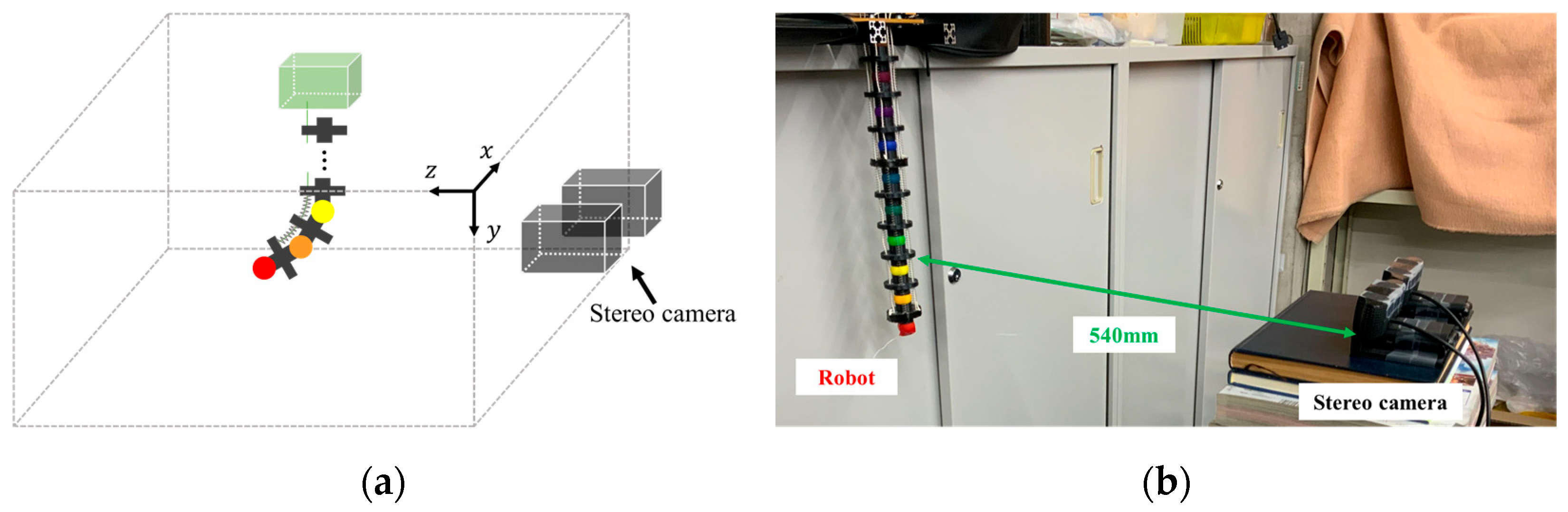
3.1. System Configuration

We constructed a system to visually detect the robot’s posture. As noted in Section 2.1, each ball has a different color. By detecting each color using a stereo camera, the 3D coordinates of each joint are obtained to estimate the robot’s posture.
The flow of posture sensing is as follows:
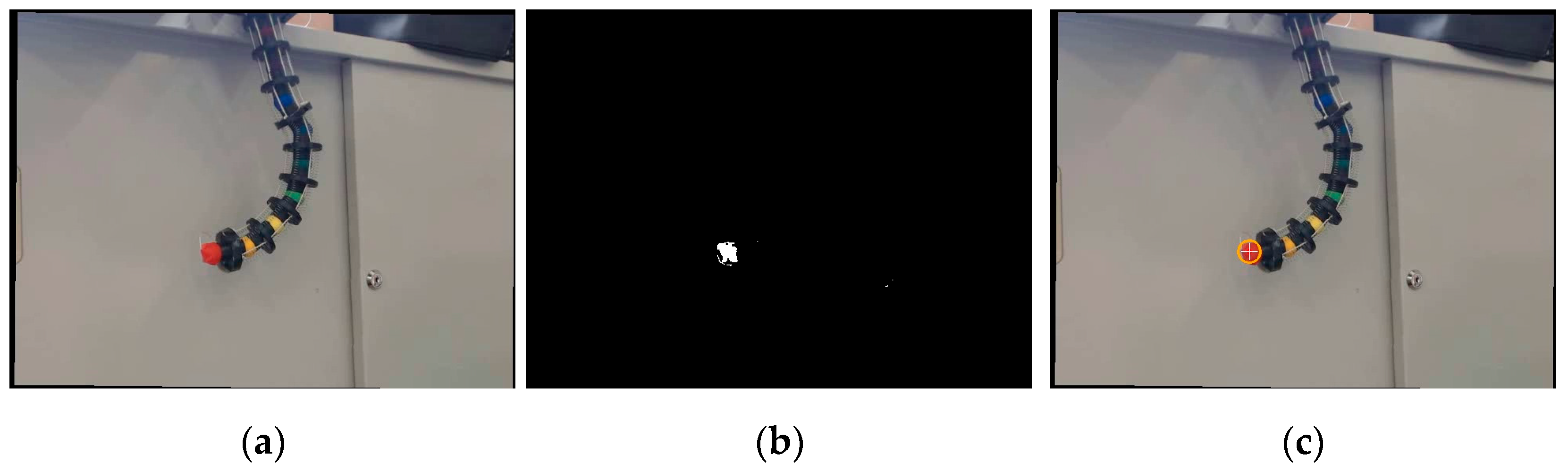
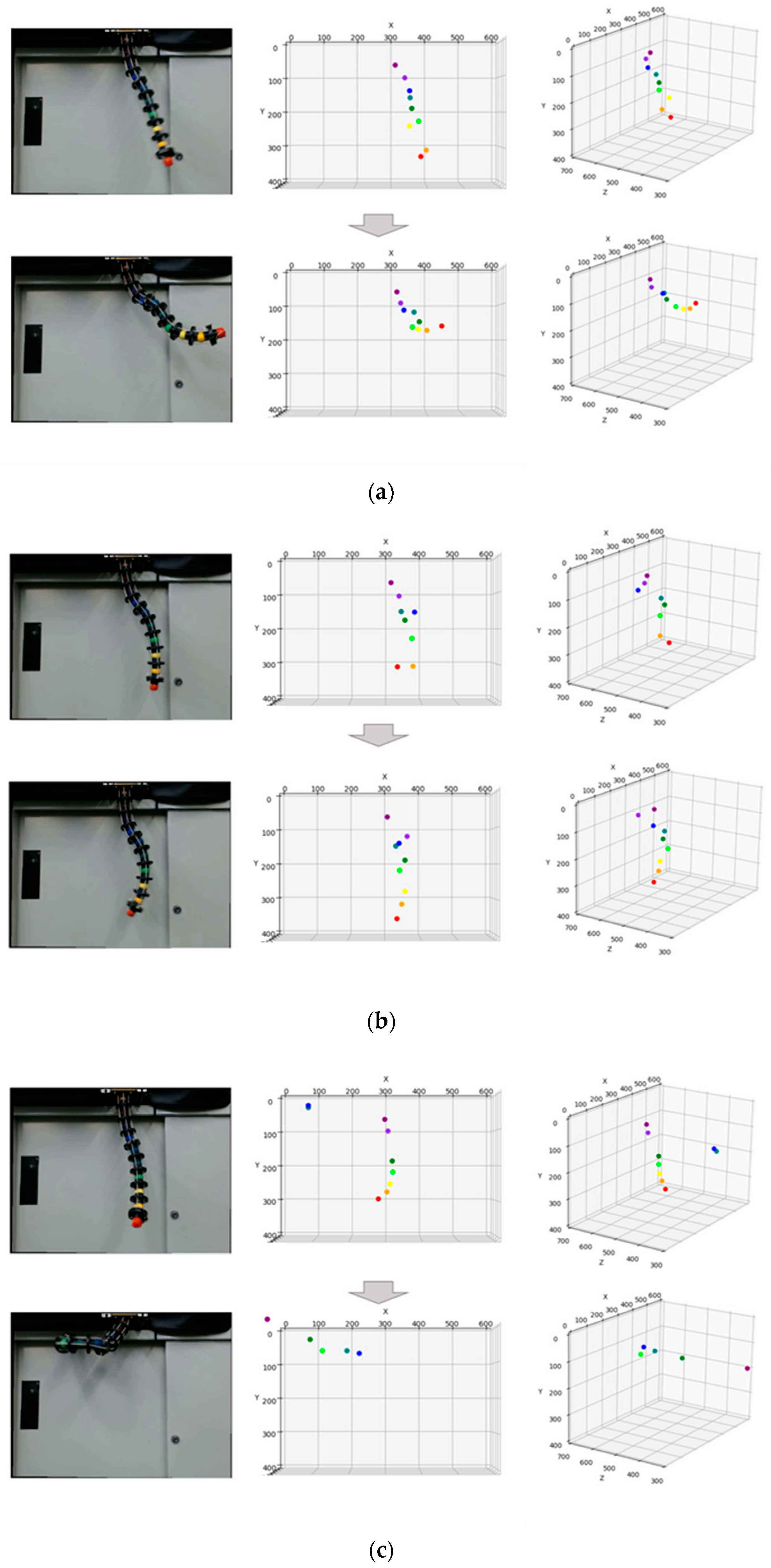
  • Obtain a mask image that extracts only the target color by using a specified range of Hue values in the HSV color space.
  • Apply a Hough transform to the obtained mask image to detect the center coordinates of the ball.
  • Calculate the 3D position of the ball from the disparity of the corresponding points in the left and right images of the stereo camera.
  • These processes are performed for all nine colors applied to the robot’s joints to detect the posture of the whole body of the robot.

3.2. Position Estimation of Each Ball

Since it is not possible to directly acquire the deformation of the robotic body, we introduce the image processing technique for detecting the locations of the joints to estimate the deformation. The robot makes 3D bending, and the occlusion problem has to be considered, in which some parts of the robotic body will not be observed. Here, we employ nine color-coded markers, as used in our tendon-driven finger robot [26], for the real-time motion capture and analysis [27]. By referring to the arrangement order of nine colors given to the robotic joints, the missing part of the body caused by an occlusion can be possibly estimated.
For color detection, we employ the HSV color space, which represents color in terms of three components: Hue, Saturation, and Value. In this system, the range of Hue values corresponding to each joint color was determined in advance. In the OpenCV coding, the range of Hue values is defined from 0 to 180, and we have determined the values of each color ball as presented in Table 1. Then, the input image is binarized by extracting pixels within the specified Hue value range and removing all other pixels. This process produces a mask image in which only the target color balls remain.
The position of the ball is detected using the Hough transform function in OpenCV. The function takes a mask image in the target color as input and outputs multiple circles in the image. To detect the ball joint correctly, the various constants in the function were adjusted manually according to the experimental environment. Among the multiple circles detected in the mask image, the one with the largest proportion of the target color area (the area that is white in the mask image) in the diameter in the x direction was set to be output as the ball position.
Figure 4 shows an example of the flow of detecting the red ball from one frame in the captured video. From the original image (Figure 4a), only the red region is masked, as shown in Figure 4b, and the ball position is obtained by applying the Hough transform to it, as shown in Figure 4c.
Using the difference in the center position of the ball detected by the left and right cameras, the distance between that ball and the camera was calculated by triangulation. The stereo camera is arranged in parallel and can be considered as shown in Figure 4. If we use the x-coordinates x L , x R of the object reflected in the left and right cameras, its coordinates can be expressed by the following equation.
X = B x L D Y = B y L D Z = B f D
where B is the baseline, f is the focal length, and D = x L x R is the disparity. This method makes it possible to estimate the 3D position of each joint of the robot, and these procedures are carried out for each of the nine colors to identify the overall posture of the robot.

4. Experiments and Results

An overview of the experimental environment is shown in Figure 5. The six motors used for control are controlled by an Arduino UNO, which is supplied with a voltage of 5 V from a connected DC power supply.

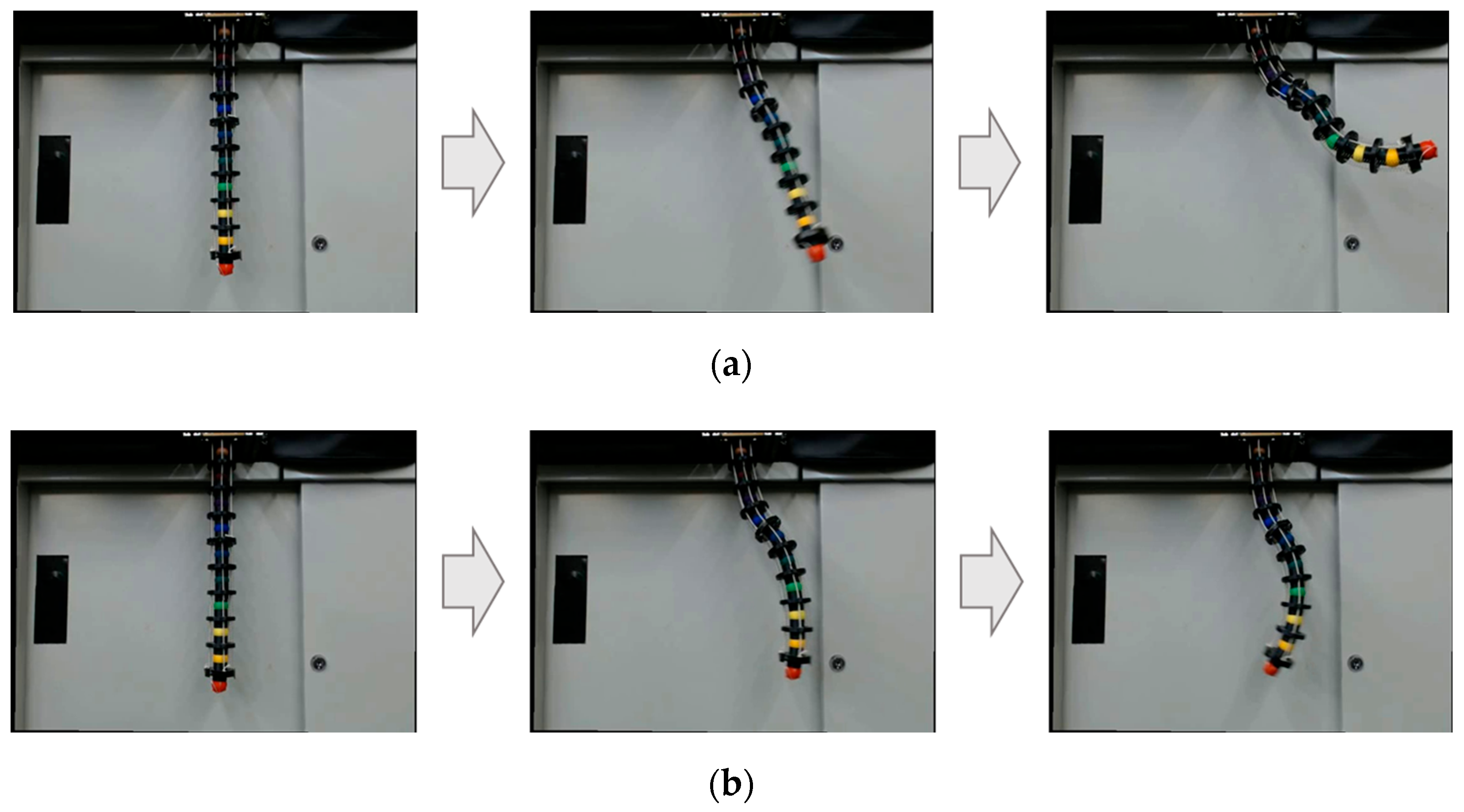
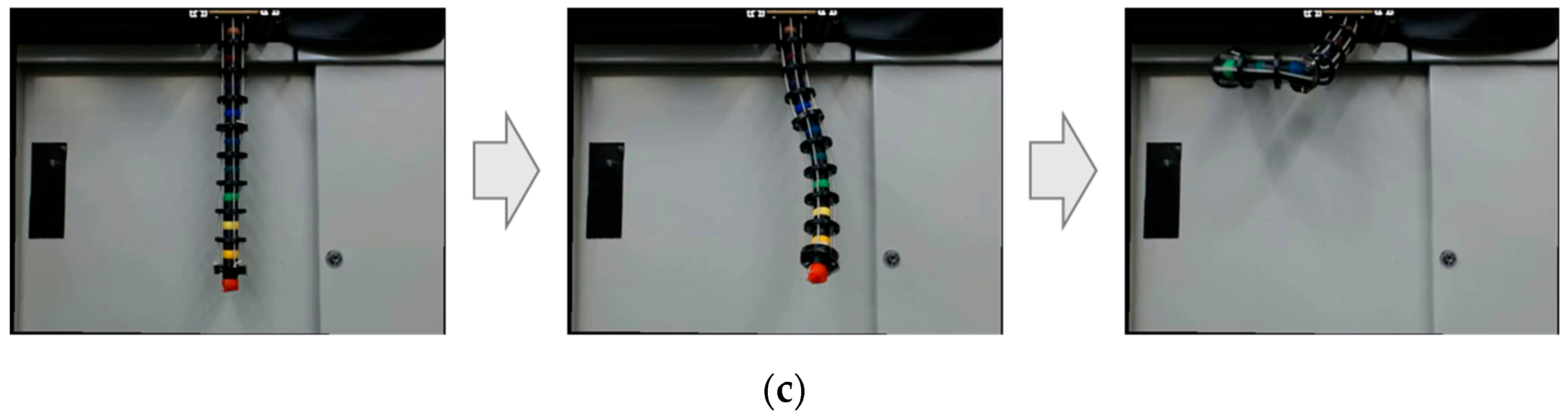
4.1. Manipulation of Continuum Robotic Body

In our previous paper [20], we already showed that a robot with a similar structure consisting of a single section can be operated to move in any direction. To verify the performance of the newly developed robot, we conducted experiments on several representative poses. The following three types of poses were employed for the evaluation:
  • One-directional bending: ( θ 1 , t 1 , θ 2 , t 2 ) = (60, 1000, 60, 2000);
  • S-shaped pose: ( θ 1 , t 1 , θ 2 , t 2 ) = (90, 1000, 270, 3000);
  • Spatial motion: ( θ 1 , t 1 , θ 2 , t 2 ) = (60, 1000, −60, 4500).
The results for each pose are shown in Figure 6. Figure 6a shows a successful simple motion that moved the entire piece in the same direction. In Figure 6b, section 1 and section 2 were driven in opposite directions, resulting in a successful S-shaped bending. In Figure 6c, by setting the bending direction and time of each section appropriately, the motion to wrap around the object was successfully achieved.
These results confirm that this robot can be operated appropriately by the proposed control method.

4.2. Posture Estimation

To evaluate the performance of the proposed posture sensing system, we applied the method to motion videos to validate if the robotic postures were properly detected.
For each pose, the results of the robot motion and the detected posture are shown in Figure 7, which presents the pictures from the left camera and the corresponding posture detection results, with two selected frames for each movement. For each frame, the posture detection results are shown in two plots, one in the x - y plane, which has the same viewpoint as the stereo camera (shape in x - y plane), and the other from a diagonal viewpoint for showing the 3D articulated shape (measured 3D shape).
Table 2 shows the error in Euclidean distance of the detected position of each ball from the actual position, which is calculated by manually specifying the center point of each ball from the left and right frame images. In the table, the error values in millimeters for each color ball in the six frames shown in Figure 7 (two frames for each of the three types of motions) are presented, and “-” indicates detection failure. We verified that the developed posture sensing system could properly detect the position of each joint in order to recognize the whole posture of the robotic body when the balls were clearly visible from the stereo camera. When a ball joint was hidden or invisible due to the occlusion and low-lighting condition, the system outputs an error value, which resulted in greater error values exceeding 100 mm (e.g., the yellow in the first frame of the S-shaped pose was not detected correctly).
The average error value, excluding the detection failure, was 19.5 mm. This robot has been developed to grasp an object by the wrapping action, effectively employing its flexibility and redundancy, and the recognition error is considered to be small enough to conduct the grasping performance. Since the body is a continuum, the errors of estimated ball locations are corrected by interpolation by referring to adjacent ball locations during the wrapping manipulation, allowing larger errors to be adjusted properly.

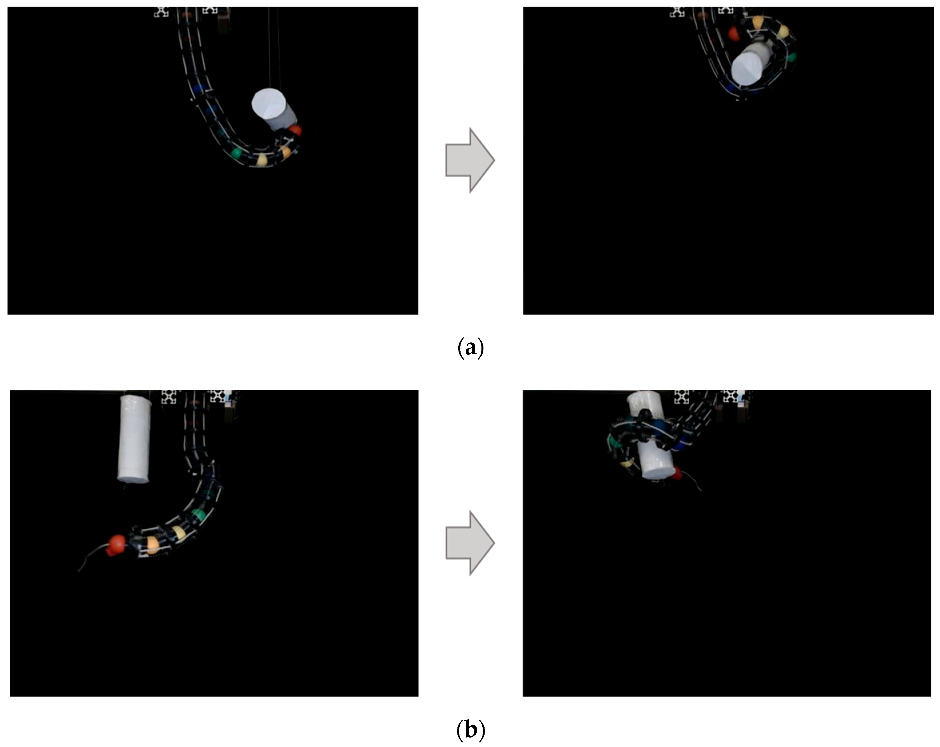
4.3. Grasping Experiment

In this experiment, we verify whether the robot’s redundant body structure robustly grasps an object placed in different postures by roughly recognizing the object’s shape and location. To execute the grasping performance of the robot, we employed a cylindrical-shaped object with 45 mm in diameter and 10 g in weight. In the experiment, the object was suspended by a thin string in two different postures, horizontally oriented and vertically oriented.
For the horizontally oriented object, the robot grasped by wrapping itself around the object from below, in which inputs are ( θ 1 , t 1 , θ 2 , t 2 ) = (60, 500, 60, 4500). On the other hand, for vertically oriented objects, the robot grasped by wrapping itself around the object from the left side, in which inputs are ( θ 1 , t 1 , θ 2 , t 2 ) = (60, 800, −60, 4500). As shown in Figure 8, our robot properly grasped the objects by the wrapping actions. We verified that the proposed structure of a two-section body and the independent driving method enabled the wrapping articulation from the two different directions and successfully grasped the cylindrical object.

5. Discussion

As shown in Figure 7, the detection of the balls situated on the base side (e.g., purple ball) is comparatively lower. There are two possible reasons. Firstly, the balls closer to the base have a smaller V value in HSV due to the lighting conditions, which makes the color closer to dark. We expect that the lighting arrangement will improve the brightness and the system will detect the correct location. Secondly, the base side balls appear smaller than the tip side balls due to the location of the camera and the robot, causing detection failures and false positives. This problem can be solved by adjusting the location of the robot and the stereo camera. In addition, the reachable area of the ball on the base side is smaller than that of the ball on the tip side, and the significance of acquiring the position of the base side ball is considered to be relatively low.
As evident from Figure 7c, when the robot is in certain poses, some parts of its body may fall outside the camera’s field of view, making it difficult to accurately detect the overall pose of the robot. The proposed posture sensing system is intended to generate training data for future machine learning applications. Therefore, the existence of poses that cannot be correctly detected is a critical issue that significantly impacts the reliability of the system. To address this problem, we believe that conducting experiments while adjusting the camera position according to the robot’s pose can be an effective solution. Although changing the camera position will alter the obtained coordinate values, this issue can be handled by applying appropriate coordinate transformations.

6. Conclusions

In this study, we developed a continuum robot system with color-based posture sensing. The robot features a two-part driven structure that allows it to grasp objects through complex movements. To enable autonomous control of the developed robot, we implemented a posture sensing system that utilizes color-coded joints and stereo camera technology. Each joint of the robot is painted a distinct color, enabling the stereo camera to detect and track the 3D coordinates of each joint.
Experimental results demonstrated the effectiveness of the visual posture sensing system in various postures. Furthermore, the developed robot successfully grasped objects in various postures.
In future research, the following efforts will be made to develop an autonomous object grasping system using this robot. First, by introducing a machine learning technique, the association between control commands and the robotic shape bending will be constructed for better grasping performance. The robotic shape bending will be accurately obtained, and thereby an automatic grasping system, which can adaptively grasp various objects with different shapes and softness/hardness, will be constructed. It is expected that an autonomous robotic control will be realized for intuitively and efficiently grasping various objects. Next, we will examine the effect of the order of the tendon actuations on the final posture. Currently, the order of the actuations is preliminary given; however, changing this order could result in different postures, even with the same actuation values due to the redundancy of the flexible body. By considering the order of actuation, we can expect to achieve a greater variety of grasping performance. We will also investigate the effect of friction between the robot and the target object on the grasping performance with regard to the object. It is expected that attaching a rubber cover or other material to the robot will increase the upper limit of the weight that can be loaded.

Author Contributions

Conceptualization, R.O. and H.S.; methodology, R.O. and H.S.; software, R.O.; validation, R.O. and H.S.; formal analysis, R.O.; investigation, R.O.; resources, H.S.; data curation, R.O.; writing—original draft preparation, R.O.; writing—review and editing, H.S.; visualization, R.O.; supervision, H.S.; project administration, H.S.; funding acquisition, H.S. All authors have read and agreed to the published version of the manuscript.

Funding

This research was funded by JSPSKAKENHI Grant-in-Aid for Scientific Research(B)20H04214.

Data Availability Statement

The original contributions presented in the study are included in the article.

Conflicts of Interest

The authors declare no conflicts of interest.

References

  1. Hannan, M.W.; Walker, I.D. The “Elephant Trunk” Manipulator, Design and Implementation. In Proceedings of the 2001 IEEE/ASME International Conference on Advanced Intelligent Mechatronics. Proceedings (Cat. No.01TH8556), Como, Italy, 8–12 July 2001; Volume 1, pp. 14–19. [Google Scholar]
  2. Liu, Y.; Ge, Z.; Yang, S.; Walker, I.D.; Ju, Z. Elephant’s Trunk Robot: An Extremely Versatile Under-Actuated Continuum Robot Driven by a Single Motor. J. Mech. Robot. 2019, 11, 051008. [Google Scholar] [CrossRef]
  3. Mochiyama, H.; Gunji, M.; Niiyama, R. Ostrich-Inspired Soft Robotics: A Flexible Bipedal Manipulator for Aggressive Physical Interaction. J. Robot. Mechatron. 2022, 34, 212–218. [Google Scholar] [CrossRef]
  4. Laschi, C.; Cianchetti, M.; Mazzolai, B.; Margheri, L.; Follador, M.; Dario, P. Soft Robot Arm Inspired by the Octopus. Adv. Robot. 2012, 26, 709–727. [Google Scholar] [CrossRef]
  5. Fan, Y.; Liu, D.; Ye, L. A Novel Continuum Robot with Stiffness Variation Capability Using Layer Jamming: Design, Modeling, and Validation. IEEE Access 2022, 10, 130253–130263. [Google Scholar] [CrossRef]
  6. Tsukagoshi, H.; Kitagawa, A.; Segawa, M. Active Hose: An Artificial Elephant’s Nose with Maneuverability for Rescue Operation. In Proceedings of the Proceedings 2001 ICRA. IEEE International Conference on Robotics and Automation (Cat. No.01CH37164), Seoul, Republic of Korea, 21–26 May 2001; Volume 3, pp. 2454–2459. [Google Scholar]
  7. Buckingham, R.; Graham, A. Nuclear Snake-arm Robots. Ind. Robot Int. J. 2012, 39, 6–11. [Google Scholar] [CrossRef]
  8. Burgner-Kahrs, J.; Rucker, D.C.; Choset, H. Continuum Robots for Medical Applications: A Survey. IEEE Trans. Robot. 2015, 31, 1261–1280. [Google Scholar] [CrossRef]
  9. Schmitz, A.; Treratanakulchai, S.; Berthet-Rayne, P.; Yang, G.-Z. A Rolling-Tip Flexible Instrument for Minimally Invasive Surgery. In Proceedings of the 2019 International Conference on Robotics and Automation (ICRA), Montreal, QC, Canada, 20–24 May 2019; pp. 379–385. [Google Scholar]
  10. Yoshikawa, D.; Shimizu, M.; Umedachi, T. A Single Motor-Driven Continuum Robot That Can Be Designed to Deform into a Complex Shape with Curvature Distribution. ROBOMECH J. 2023, 10, 18. [Google Scholar] [CrossRef]
  11. Braganza, D.; McIntyre, M.L.; Dawson, D.M.; Walker, I.D. Whole Arm Grasping Control for Redundant Robot Manipulators. In Proceedings of the 2006 American Control Conference, Minneapolis, MN, USA, 14–16 June 2006; p. 6. [Google Scholar]
  12. Asano, F.; Luo, Z.-W.; Yamakita, M.; Hosoe, S. Dynamic Modeling and Control for Whole Body Manipulation. In Proceedings of the Proceedings 2003 IEEE/RSJ International Conference on Intelligent Robots and Systems (IROS 2003) (Cat. No.03CH37453), Las Vegas, NV, USA, 27–31 October 2003; Volume 4, pp. 3162–3167. [Google Scholar]
  13. Li, C.; Rahn, C.D. Design of Continuous Backbone, Cable-Driven Robots. J. Mech. Des. 2002, 124, 265–271. [Google Scholar] [CrossRef]
  14. Huang, X.; Zou, J.; Gu, G. Kinematic Modeling and Control of Variable Curvature Soft Continuum Robots. IEEEASME Trans. Mechatron. 2021, 26, 3175–3185. [Google Scholar] [CrossRef]
  15. Thuruthel, T.G.; Falotico, E.; Renda, F.; Laschi, C. Model-Based Reinforcement Learning for Closed-Loop Dynamic Control of Soft Robotic Manipulators. IEEE Trans. Robot. 2019, 35, 124–134. [Google Scholar] [CrossRef]
  16. Webster, R.J.; Jones, B.A. Design and Kinematic Modeling of Constant Curvature Continuum Robots: A Review. Int. J. Robot. Res. 2010, 29, 1661–1683. [Google Scholar] [CrossRef]
  17. Morimoto, R.; Nishikawa, S.; Niiyama, R.; Kuniyoshi, Y. Model-Free Reinforcement Learning with Ensemble for a Soft Continuum Robot Arm. In Proceedings of the 2021 IEEE 4th International Conference on Soft Robotics (RoboSoft), New Haven, CT, USA, 12–16 April 2021; pp. 141–148. [Google Scholar]
  18. Ji, G.; Yan, J.; Du, J.; Yan, W.; Chen, J.; Lu, Y.; Rojas, J.; Cheng, S.S. Towards Safe Control of Continuum Manipulator Using Shielded Multiagent Reinforcement Learning. IEEE Robot. Autom. Lett. 2021, 6, 7461–7468. [Google Scholar] [CrossRef]
  19. Wang, X.; Li, Y.; Kwok, K.-W. A Survey for Machine Learning-Based Control of Continuum Robots. Front. Robot. AI 2021, 8, 730330. [Google Scholar] [CrossRef] [PubMed]
  20. Onose, R.; Sawada, H. A Ball-Jointed Tendon-Driven Continuum Robot with Multi-Directional Operability for Grasping Objects. ROBOMECH J. 2024, 11, 4. [Google Scholar] [CrossRef]
  21. Niu, G.; Zhang, Y.; Li, W. Path Planning of Continuum Robot Based on Path Fitting. J. Control Sci. Eng. 2020, 2020, 8826749. [Google Scholar] [CrossRef]
  22. Seleem, I.A.; El-Hussieny, H.; Ishii, H. Imitation-Based Motion Planning and Control of a Multi-Section Continuum Robot Interacting with the Environment. IEEE Robot. Autom. Lett. 2023, 8, 1351–1358. [Google Scholar] [CrossRef]
  23. Camarillo, D.B.; Loewke, K.E.; Carlson, C.R.; Salisbury, J.K. Vision Based 3-D Shape Sensing of Flexible Manipulators. In Proceedings of the 2008 IEEE International Conference on Robotics and Automation, Pasadena, CA, USA, 19–23 May 2008; pp. 2940–2947. [Google Scholar]
  24. Li, J.; Sun, Y.; Su, H.; Zhang, G.; Shi, C. Marker-Based Shape Estimation of a Continuum Manipulator Using Binocular Vision and Its Error Compensation. In Proceedings of the 2020 IEEE International Conference on Mechatronics and Automation (ICMA), Beijing, China, 13–16 October 2020; pp. 1745–1750. [Google Scholar]
  25. Xu, W.; Foong, R.P.L.; Ren, H. Maker Based Shape Tracking of a Flexible Serpentine Manipulator. In Proceedings of the 2015 IEEE International Conference on Information and Automation, Lijiang, China, 8–10 August 2015; pp. 637–642. [Google Scholar]
  26. Liu, R.; Zheng, H.; Hliboký, M.; Endo, H.; Zhang, S.; Baba, Y.; Sawada, H. Anatomically-Inspired Robotic Finger with SMA Tendon Actuation for Enhanced Biomimetic Functionality. Biomimetics 2024, 9, 151. [Google Scholar] [CrossRef] [PubMed]
  27. Wang, R.; Paris, S.; Popović, J. Practical Color-Based Motion Capture. In Proceedings of the 2011 ACM SIGGRAPH/Eurographics Symposium on Computer Animation, Vancouver, BC, Canada, 5–7 August 2011; Association for Computing Machinery: New York, NY, USA, 2011; pp. 139–146. [Google Scholar]
Figure 1. Structure and appearance of the robot: (a) Appearance of the whole robot. (b) Close-up view. (c) Placement of tendons.
Actuators 14 00140 g001
Figure 2. Bending direction: (a) Placement of tendon and bending direction. (b) Bending direction and Δ r n i . (c) Bent robotic body.
Actuators 14 00140 g002
Figure 3. Configuration of sensing system: (a) Schematic of configuration. (b) Actual system configuration.
Actuators 14 00140 g003
Figure 4. Ball detection flow: (a) Original frame. (b) Mask. (c) Frame with circle.
Actuators 14 00140 g004
Figure 5. Experimental environment.
Actuators 14 00140 g005
Figure 6. Result of manipulation: (a) One-directional bending. (b) S-shaped pose. (c) Spatial motion.
Actuators 14 00140 g006aActuators 14 00140 g006b
Figure 7. Result of posture sensing: (a) One-directional bending. (b) S-shaped pose. (c) Spatial motion.
Actuators 14 00140 g007
Figure 8. Result of grasping: (a) Grasping of horizontal oriented object. (b) Grasping of vertical oriented object.
Actuators 14 00140 g008
Table 1. Colors and corresponding Hues in OpenCV.
ColorRange of Hue
red1~6
orange14~22
yellow24~31
lime40~79
green80~99
teal100~109
blue108~120
blue–violet125~138
purple168~179
Table 2. Positional errors.
MovementFrameError [mm]
RedOrangeYellowLimeGreenTealBlueBlue–VioletPurple
One-directional bending1st19.1541.3931.8125.693.776.8329.2013.8235.69
2nd10.183.0113.8811.1039.9724.2527.346.5928.80
S-shaped pose1st4.7863.096062.2037.336.0211.12113.9034.115.12
2nd7.458.4112.9032.0913.8412.3435.95108.7322.11
Spatial
motion
1st4.153.325.0323.2516.17474.07480.5827.6628.36
2nd---13.77202.098.5030.89--
Disclaimer/Publisher’s Note: The statements, opinions and data contained in all publications are solely those of the individual author(s) and contributor(s) and not of MDPI and/or the editor(s). MDPI and/or the editor(s) disclaim responsibility for any injury to people or property resulting from any ideas, methods, instructions or products referred to in the content.

