Article

MPC-Based Speed Tracking Control for Subway Trains Under Actuator Constraints

by
Dongdong Liu
1,
Guojun Yan
2,
Jing Zhou
3,* and
Bo Chen
3
1
Ningbo Rail Transit Group Co., Ltd., Ningbo 315100, China
2
Hangzhou Qiji Feiteng Information Technology Studio, Hangzhou 310015, China
3
Department of Automation, Zhejiang University of Technology, Hangzhou 310023, China
*
Author to whom correspondence should be addressed.
Actuators 2025, 14(3), 134; https://doi.org/10.3390/act14030134
Submission received: 10 January 2025 / Revised: 4 March 2025 / Accepted: 8 March 2025 / Published: 10 March 2025
(This article belongs to the Section Actuators for Surface Vehicles)

Abstract

:
In this paper, we propose a model predictive control (MPC)-based approach for the speed tracking control of subway trains, specifically designed to handle the complexities of constrained optimization in real-world applications. The control strategy accounts for nonlinearities, actuator constraints, and disturbances and is validated using real operational data from the Ningbo Metro Line 7. Unlike traditional PID controllers, which are limited by their inability to handle dynamic changes and nonlinear systems, the MPC method optimizes control inputs by predicting future system behavior and adapting to variations in speed profiles. The effectiveness of the proposed MPC-based controller is demonstrated through a comparison with the PID control system already deployed on the metro line. Our results show that MPC provides superior speed tracking performance, particularly in dynamic and disturbed operating conditions, highlighting its potential advantages for real-world subway train control systems.

1. Introduction

As urbanization progresses in China, the growing demand for higher transport capacity and the increasing expectations for superior service pose significant challenges to urban transportation systems. Urban rail transit, with its numerous advantages, has emerged as a vital solution to public transportation issues in cities [1]. The automatic train operation (ATO) system is crucial for enabling the automation of urban rail trains [2]. An efficient ATO system not only enhances the operational efficiency of rail transit, but also plays a critical role in alleviating urban traffic congestion.
The ATO system automatically calculates and transmits the appropriate control commands to the train based on current state data, enabling the train to operate autonomously between stations [3]. The core of automatic train operation lies in the high-quality speed control of the ATO system, which is essential to meet various operational requirements [4]. A key component of the ATO system is the automatic train speed adjustment module, which autonomously calculates and adjusts the train speed using available information. Specifically, train speed tracking control based on a given speed profile significantly impacts train running time, energy consumption, stopping accuracy, and passenger experience, exemplifying the automation and intelligence of the system [5,6].
To design more stable and effective controllers, scholars both domestically and internationally have conducted extensive research on train speed profile tracking control strategies using various control methods, such as PID control [7], back-stepping control [8], fuzzy control [9], sliding mode control [10], and adaptive control [11]. Pu et al. considered the time-varying parameters of train motion and established a train model with dynamic parameters [12]. They proposed a model-free adaptive controller combining neural networks and PID algorithms to achieve speed tracking control. Yuan et al. presented an improved minimum variance self-tuning regulator for adaptive speed tracking control of high-speed trains, which incorporated an attenuation factor and the Chebyshev series for robustness to stochastic disturbances and parameter uncertainties [13]. A fuzzy control method was introduced in [14] to track the desired speed profile of electric trains while preventing wheel slip, with simulations showing effective tracking and slip management under various conditions. Mao et al. proposed a novel adaptive fault-tolerant sliding mode control scheme for high-speed trains, focusing on the longitudinal dynamics model and considering disturbances and actuator faults [15]. A double-layer hierarchical exponential reaching law-based global fast terminal fuzzy sliding mode controller was proposed in [16], incorporating an exponential reaching law to adjust the sliding mode surface’s dynamic properties, allowing rapid convergence to a stable state and eliminating chattering in the controller.
However, the operation of high-speed trains is a highly nonlinear process with numerous unpredictable uncertainties. For example, passenger boarding, alighting and variations in luggage weight during stops can affect the train’s dynamics. Different weather conditions can alter the basic drag coefficient obtained from wind tunnel tests. Additionally, inevitable external factors such as tunnel resistance, gradient resistance, and aerodynamic drag further complicate speed tracking control. Moreover, the physical structural properties and actual working environment of train actuators constrain their output, leading to actuator saturation [17]. This phenomenon affects the control signals of the train control system, preventing the actuator’s output signal from fully aligning with the control signal. Consequently, it affects the performance of the closed-loop system and can potentially compromise system stability. MPC has been widely adopted in industrial applications due to its ability to manage complex, constrained control problems effectively [18,19]. It can adapt to non-linearities, system constraints, and disturbances by predicting future system behavior and optimizing control inputs accordingly. Compared to traditional PID controllers, which are often limited by their inability to handle non-linear systems or dynamic changes in parameters, MPC provides a more robust and precise solution, especially for high-speed trains and urban rail systems where rapid response and high accuracy are required. MPC has been widely applied in fields such as autonomous driving of electric vehicles, where several methods focus on adaptive prediction-based control and energy management under varying driving conditions, as demonstrated in [20,21,22]. However, despite its success in these applications, there remains a gap in the application of MPC to automatic train operation in urban rail systems, where the unique characteristics of train dynamics and operational constraints present additional challenges. Cao et al. applied fuzzy predictive control technology to ATO systems, presenting a strategy that combines fuzzy logic with predictive control to handle uncertainties and dynamic changes in the system, thus enhancing the accuracy and passenger comfort of train operations [23]. Chen et al. proposed a data-driven Koopman MPC method, which utilizes the Koopman operator to build a linearized high-dimensional dynamic model capable of addressing the nonlinear and time-varying characteristics of train operations [24]. Through an online update mechanism, the method effectively handles the challenges posed by changing dynamic train characteristics. Similarly, Wang et al. focused on the robust control of heavy haul trains under imperfect communication conditions, introducing a robust optimal predictive control approach to ensure that the trains maintain stable operation even in the event of communication disruptions [25]. Furthermore, Wang and Tang developed a fuzzy model predictive control (FMPC) method, which optimizes high-speed train speed control and energy efficiency, overcoming challenges related to nonlinear dynamics faced by traditional MPC approaches [26]. Yang et al. proposed a hybrid model predictive control (HMPC) method, combining MPC with other control strategies to optimize the operation of high-speed trains, balancing energy efficiency and operational safety, especially in complex track environments [27]. Lastly, Xu et al. introduced an adaptive model predictive control (AMPC) method to address the cruise control problem of high-speed trains, particularly under time-varying parameters and external disturbances. This method ensures precise speed tracking control and guarantees operational stability [28]. Motivated by the above analysis, this paper explores subway speed tracking control under actuator constraints and validates the proposed method using real operational data from Ningbo Metro Line 7. The key innovations of this study are as follows: (1) A novel MPC-based speed tracking control method is developed, considering multiple forces and disturbances, which significantly improves passenger comfort and stopping accuracy, addressing the challenges posed by actuator limitations and dynamic variations in real-world conditions. (2) The effectiveness of the proposed algorithm is demonstrated through validation with real operational data, including speed profiles, speed limits, and station data, from the YLZ-YFL section of Ningbo Metro Line 7, offering a comprehensive evaluation in a practical urban rail transit setting.
Notation: The symbol N and R denote the set of natural and real, respectively. diag { · } stands for a block diagonal matrix. col { · } is a column vector. For sets S and W, | S | denotes the cardinality of S. For a vector x = col { x 1 , . . . , x n } R n , the 1 norm, | | x | | 1 , is the sum of all components of x. The support of x is a set defined as supp ( x ) { i | 1 i n , x i 0 } . For a matrix M R n × m , M represents its transpose. I m × n and 0 m × n denote the identity and zero matrix with m × n dimension, respectively.

2. Dynamical Model of Train

In this section, a comprehensive continuous-time model of train operation is presented. The analysis encompasses control signals, traction/braking forces, resistance, and dynamic environmental parameters.

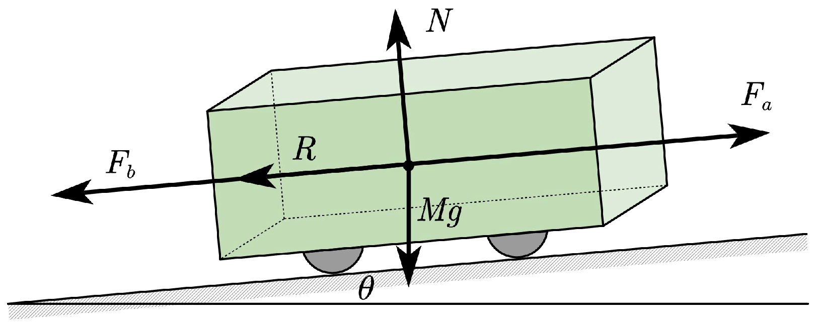
2.1. Train Force Analysis

In order to establish the dynamic mathematical model of a high-speed train, it is necessary to analyze various external forces on the train. Considering the complexity of the calculation, there are usually two kinds of train model: single-particle and multi-particle models. Single-particle models are more convenient for modeling and calculation, but neglect the force between vehicles and other factors. Multi-particle models model can simulate the train operation more accurately and the calculation is more in line with the reality. However, the model is relatively complex and requires more computing resources and time for analysis.
The train is modeled as a single point mass, where its motion is described by a single position and velocity vector, neglecting the interaction between individual cars. The train is primarily subjected to three external forces: the traction force F a , generated by the train’s propulsion system, the resistance force R, which arises from various factors during operation, and the braking force F b , generated by the braking system. It is important to note that the traction and braking forces cannot act simultaneously during train operation. Figure 1 provides a schematic representation of the forces acting on the train during operation. Additionally, M g represents the gravitational force acting on the train, N denotes the normal force exerted by the track on the train, and θ refers to the track’s gradient.

2.2. Train Motion Model

When treating the train as a point mass and applying Newton’s laws, the longitudinal motion equation of the train can be described as [12]
M ˜ ( t ) x ˙ ( t ) = F ( t ) R ( t ) M ˜ ( t ) = ( 1 + γ ) M ( t )
where t represents the running time. M ˜ ( t ) is the rotational mass of the train. x ( t ) is the speed of the train, F ( t ) is the traction/braking force generated by the traction/braking system. R ( t ) is the resistance that acts on the train and is influenced by the characteristics of the train and environmental conditions. During operation, the train’s mass does not match its static mass, a phenomenon caused by the moment of inertia. In dynamic calculations, the train’s mass is corrected to the rotational mass. The formula for calculating the rotational mass is shown in (1). Here, γ is the rotational mass coefficient. M ( t ) is the total static mass of the train, which includes the vehicle mass and the passenger mass.

2.3. Traction/Braking Force

Train operation is driven by electric motors through traction/braking control. The maximum output of traction and braking force from the electric motors varies with the operating speed of the train. Typically, the traction/braking characteristic curves include both constant and variable phases. At specific train speeds, the maximum traction/braking force can be calculated as
F a   max ( t ) = f a   max ( x ( t ) ) F b   max ( t ) = f b   max ( x ( t ) )
where F a   max ( t ) is the maximum traction force. F b   max ( t ) is the maximum braking force. f a   max ( x ( t ) ) is the function that describes the relationship between the maximum traction force and the speed of the train, and f b   max ( x ( t ) ) is the function describing the relationship between the maximum braking force and the speed of the train.
As many studies have shown, the ATO system determines the signal for the percentage of force output. Therefore, the output percentage of the maximum traction/braking force is used as the train control signal u ( t ) . The train traction/braking force F ( t ) can be calculated using the following equation:
F ( t ) = u ( t ) F max ( t ) = u ( t ) f a max ( x ( t ) ) , Ξ 1 ( t ) = 1 , Ξ 2 ( t ) = 0 0 , Ξ 1 ( t ) = 0 , Ξ 2 ( t ) = 0 u ( t ) f b max ( x ( t ) ) , Ξ 1 ( t ) = 0 , Ξ 2 ( t ) = 1
where F max ( t ) is the maximum traction/braking force. u ( t ) is the percentage of the maximum traction/braking force. 0 u ( t ) 1 . Ξ 1 ( t ) and Ξ 2 ( t ) are command indicators.

2.4. Resistance Force

Train resistance is a significant component of train operation. Considering the basic resistance, gradient resistance, and uncertain disturbances, it is expressed as
R ( t ) = R b ( t ) + R g ( t ) + d ( t )
The basic resistance is typically expressed as a second-order polynomial of speed, known as the Davis formula [2]:
R b ( t ) = a ( t ) + b ( t ) x ( t ) + c ( t ) x 2 ( t )
where a ( t ) , b ( t ) , and c ( t ) are empirical parameters. The basic resistance is mainly caused by mechanical resistance and aerodynamic resistance. In this study, the basic resistance parameters are considered to differ between subway trains operating above ground and those operating underground. Therefore, the basic resistance parameters can be described in a piecewise way.
Gradient resistance is caused by the track gradient and can be expressed as
R g ( t ) = M ( t ) g sin ( arctan ( ι ( t ) ) )
where M ( t ) represents the train’s mass, g is the gravitational acceleration, and ι ( t ) is the track gradient, which is the ratio of vertical to horizontal displacement along the track.
For small gradients, we can simplify the expression using the first-order approximation derived from the Taylor series expansion of the trigonometric functions sin and tan. Specifically, for small values of ι ( t ) , the Taylor expansions of sin ( θ ) and tan ( θ ) are
sin ( θ ) = θ θ 3 6 + O ( θ 5 ) tan ( θ ) = θ + θ 3 3 + O ( θ 5 )
Since the gradient ι ( t ) is typically small (as required by track construction standards), we approximate sin ( arctan ( ι ( t ) ) ) as
sin ( arctan ( ι ( t ) ) ) arctan ( ι ( t ) ) ι ( t )
Thus, the gradient resistance can be approximated as
R g ( t ) M ( t ) g ι ( t )
This approximation is valid for small gradients and is commonly used in railway engineering to simplify the calculation of gradient resistance in track systems with low slopes. The use of this approximation ensures that the model remains tractable while maintaining sufficient accuracy for typical operational conditions.

2.5. Dynamic Train Model

To account for the uncertainties of the system, the disturbance during the operation of the train is represented by d ( t ) . Based on the above analysis, the longitudinal motion model of the train can be expressed as
( 1 + γ ) M ( t ) x ˙ ( t ) = u ( t ) Γ ( t ) Ξ ( t ) H ( t ) Ω ( t ) M ( t ) g ι ( t ) d ( t )
where
Γ ( t ) = f a   max ( x ( t ) ) f b   max ( x ( t ) ) Ξ ( t ) = Ξ 1 ( t ) Ξ 2 ( t ) H ( t ) = a ( t ) b ( t ) c ( t ) Ω ( t ) = 1 x ( t ) x 2 ( t )
and
u ( t ) [ 0 , 1 ] , Ξ i ( t ) { 0 , 1 } , i = 1 2 Ξ i ( t ) 1
The train moves under the action of the resultant force, and the acceleration can be expressed by the following formula:
x ˙ ( t ) = 1 1 + γ ( u ( t ) Γ u ( t ) Ξ ( t ) + H u ( t ) Ω ( t ) + g ι ( t ) + d u ( t ) )
where
Γ u ( t ) = Γ ( t ) M ( t ) H u ( t ) = H ( t ) M ( t ) = a u ( t ) b u ( t ) c u ( t ) d u ( t ) = d ( t ) M ( t )
Γ u ( t ) is the maximum traction/braking force per unit mass of the train. H u ( t ) is the vector that contains the basic resistance parameters, and d u ( t ) is the uncertain disturbance force per unit mass.
Assuming the sampling time is T, discretizing (9) yields the discrete dynamic model for the train’s speed:
x ( k + 1 ) = f ( x ( k ) , u ( k ) ) + w ( k )
where
f ( x ( k ) , u ( k ) ) = T 1 + γ ( u ( k ) Γ u ( k ) Ξ ( k ) + H u ( k ) Ω ( k ) + g ι ( k ) ) + x ( k ) w ( k ) = T 1 + γ d u ( k )

2.6. Linearization of Train Model

To handle the complexities associated with nonlinear control systems, linearization around a steady-state operating point is often utilized. In this section, we linearize the discrete dynamic model of the train’s speed, making it more suitable for linear control design methods, such as MPC proposed in this paper.
Given the discrete dynamic model (10), we select an operating point ( x 0 ( k ) , u 0 ( k ) ) around which to linearize the system. The linearization involves expanding the function f ( x ( k ) , u ( k ) ) into a Taylor series around ( x 0 ( k ) , u 0 ( k ) ) and retaining only the linear terms.
  • Step 1. Choose the operating point ( x 0 ( k ) , u 0 ( k ) ) , which is typically obtained by MPC computing the optimization problem at each time step.
  • Step 2. Calculate the first-order Taylor expansion of f ( x ( k ) , u ( k ) ) with respect to x and u at the operating point ( x 0 ( k ) , u 0 ( k ) ) :
f ( x ( k ) , u ( k ) ) f ( x 0 ( k ) , u 0 ( k ) ) + A ( x ( k ) x 0 ( k ) ) + B ( u ( k ) u 0 ( k ) )
where
A = f x x 0 ( k ) , u 0 ( k ) = T 1 + γ u ( k ) Γ ˙ u 0 ( k ) Ξ ( k ) + b u k + 2 c u k x 0 ( k ) + 1 B = f u x 0 ( k ) , u 0 ( k ) = T 1 + γ Γ u 0 ( k ) Ξ ( k )
Γ u 0 ( k ) = [ f a max ( x 0 ( k ) ) / M ( k ) f b max ( x 0 ( k ) ) / M ( k ) ] .
  • Step 3. Obtain the following linear state space function:
x ( k + 1 ) = A x ( k ) + B u ( k ) + w ( k ) + r ( k )
where r ( k ) = f ( x 0 ( k ) , u 0 ( k ) ) A x 0 ( k ) B u 0 ( k ) .

3. MPC-Based Speed Tracking Control

In this section, we detail the design and implementation of the Model Predictive Control (MPC) scheme tailored for subway trains, specifically addressing the constraints posed by actuators. The MPC framework utilizes an optimization model that considers the dynamic behavior of the train and the physical limitations of the actuators to ensure precise speed tracking.
If the control time domain of the system is N c and the prediction time domain is N p , then the state and system output in the prediction time domain can be calculated as
X ( k + 1 ) = F x ( k ) + Φ U ( k )
where
X ( k + 1 ) = x ( k + 1 | k ) x ( k + 2 | x ) x ( k + N p | k ) , F = A A 2 A N p , U ( k ) = u ( k | k ) u ( k + 1 | k ) u ( k + N c 1 ) , Φ = B 0 0 A B B 0 A N p 1 B A N p 2 B A N p N c B
As shown in (13), the state and output variables within the prediction horizon can be calculated using the system’s initial state x ( k ) and control input U ( k ) . However, in practice, the control input of the system is unknown. It is only by setting an appropriate optimization objective and solving it that the control sequence can be obtained. Considering the system’s ability to follow the desired speed, the cost function to be minimized is defined as follows:
J 1 = i = 1 N p ( | | x ( k + i | k ) x ref ( k + i ) | | 2 Q 1 )
To minimize the control effort while achieving the desired speed tracking performance, we can design the following cost function:
J 2 = i = 1 N p ( | | u ( k + i | k ) | | 2 Q 2 )
For train control systems, smooth acceleration changes can significantly enhance passenger comfort. Hence, it can be obtained that
J 3 = i = 1 N p 1 ( | | u ( k + i + 1 | k ) u ( k + i | k ) | | 2 Q 3 )
where Q 1 , Q 2 , and Q 3 are weighting matrices that balance the importance of tracking performance, control effort, and passenger comfort, respectively.
The actuator constraints, which include both traction and braking limits, are explicitly considered in the MPC design. These constraints ensure that the control actions remain within feasible bounds to prevent actuator saturation and ensure safety.
u min ( k + i ) u ( k + i | k ) u max ( k + i ) , i = 1 , , N c
Additionally, state constraints can be imposed to ensure that the train’s speed remain within safe operational limits:
x min ( k + i ) x ( k + i | k ) x max ( k + i ) , i = 1 , , N p
Last but not least, unlike autonomous driving in general automobiles, precise stopping is crucial for the ATO system. Accurate docking at designated positions ensures that passengers can board and alight smoothly, avoiding gaps between the train and the platform, thereby reducing safety hazards. Therefore, the terminal position constraints is introduced as
p ref 0.5 p final p ref + 0.5
where p ref denotes the distance between the next station and the previous station. p final represents the distance from the previous station when the train comes to a stop, which can be calculated by integrating the speed x ( k ) .
Based on the above analysis, the MPC-based speed tracking control problem can be transformed into solving the following optimization problem:
arg min U ( k ) J 1 + J 2 + J 3 s . t . : ( 17 ) ( 19 )
The optimization (20) captures the essence of the MPC problem for subway train speed tracking under actuator constraints, ensuring both optimal performance and safety during train operations. By solving this optimization problem at each control step, the MPC controller generates control inputs that guide the train to follow the desired speed profile accurately while respecting all physical and operational constraints.

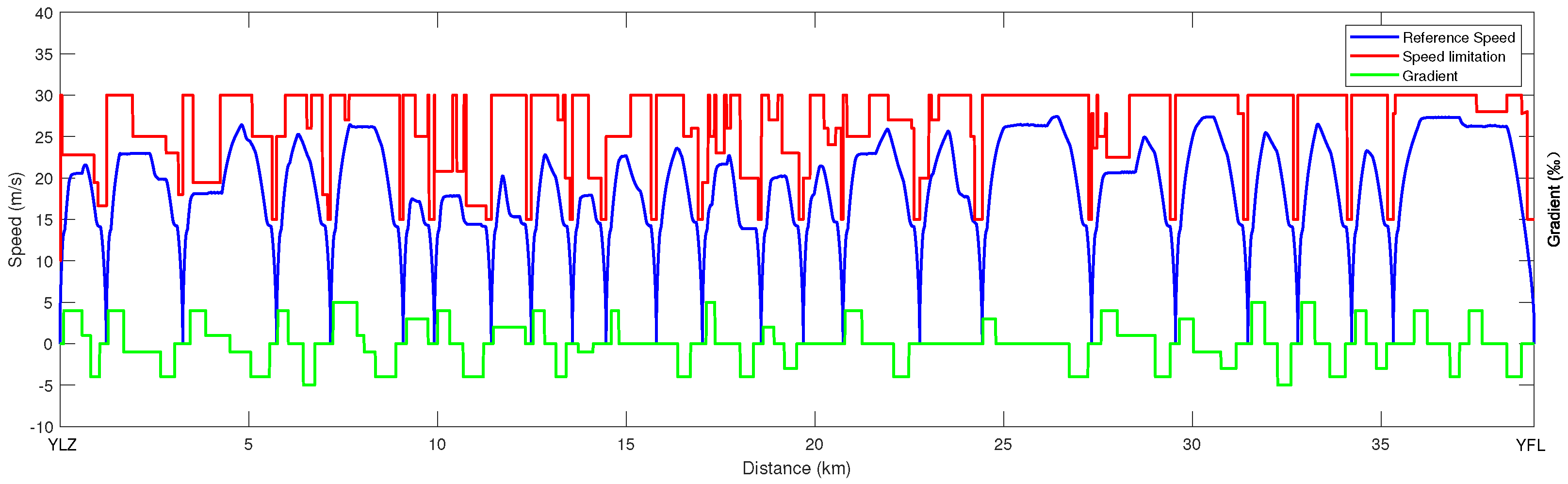
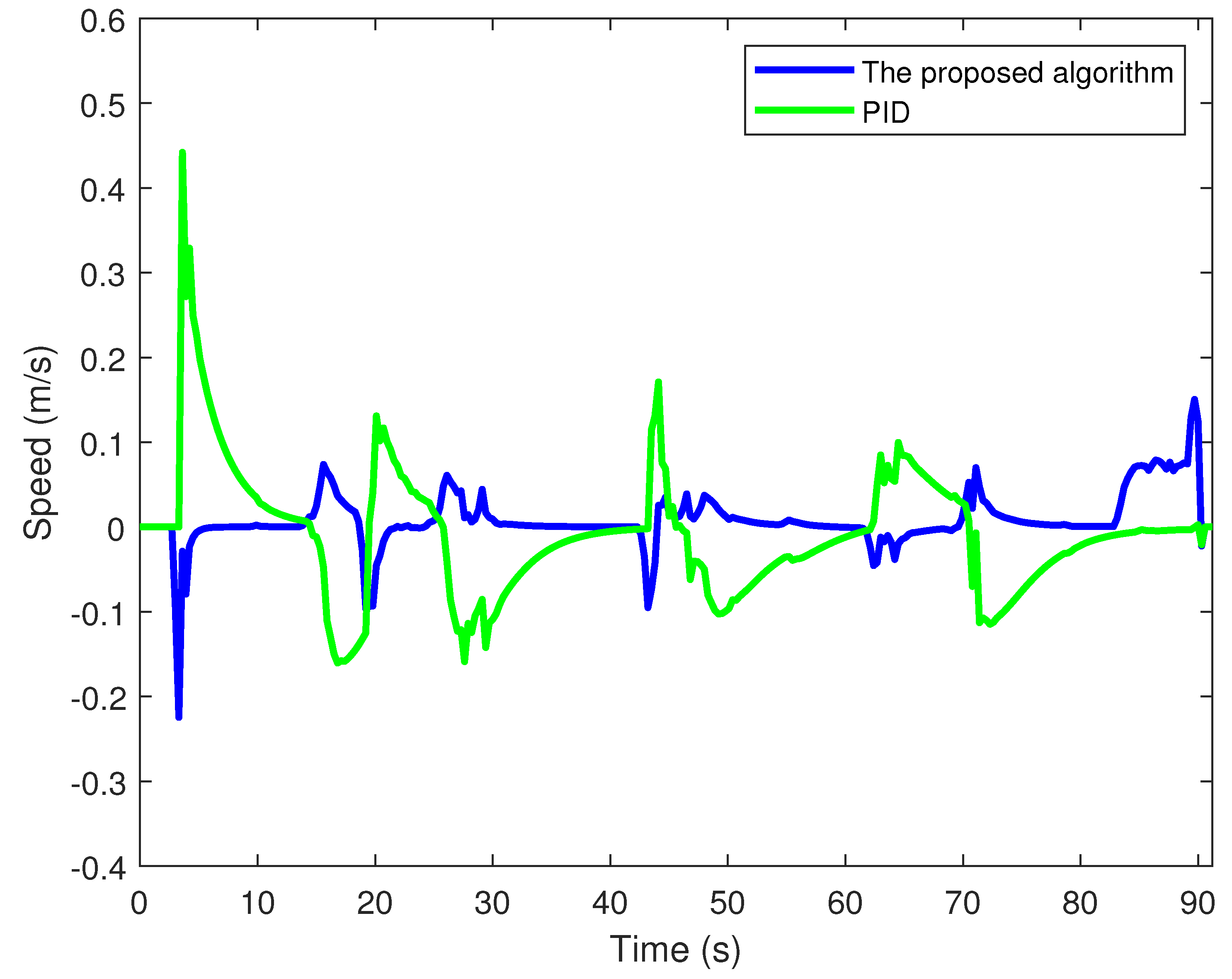
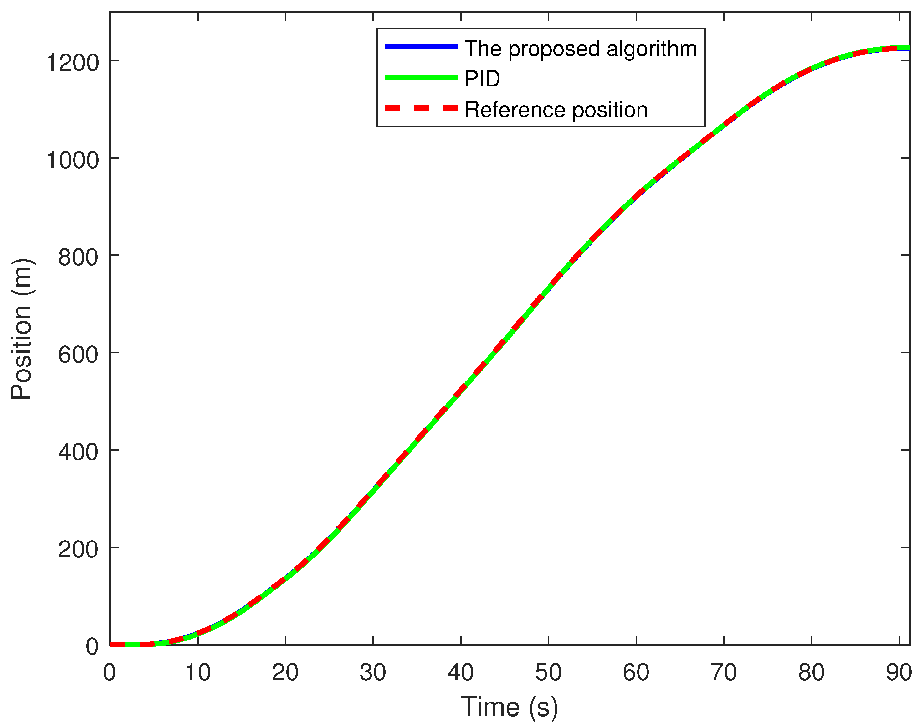
4. Simulation Results

To validate the performance of the proposed MPC-based speed tracking control scheme, we conducted the simulations that compare the proposed method with traditional PID controllers.
In this simulation, data from Ningbo Metro Line 7, specifically between Yunlong Station and Yufan Road Station, is utilized to validate the algorithm. This line consists of 25 stations and has a total length of approximately 39,066 m.
The train studied in this paper is a T07001, with an unladen weight of 212,904 kg and a fully loaded weight of 339,864 kg. Utilizing the train’s mass, rotational mass, maximum traction force, and maximum braking force, we have calculated the maximum and minimum accelerations of the train to be 1.3   m / s 2 and 1.091   m / s 2 , respectively. Different operating sections result in varying passenger loads. Hence, the train mass data used for simulations during non-peak hours is shown in Table 1. The data of speed limit, speed profile, gradient, and station position can be referred in Figure 2. Q 1 , Q 2 , and Q 3 are used to balance speed tracking accuracy, control effort, and passenger comfort in the MPC cost function, and are set to 10, 2, and 5, respectively.
To clearly demonstrate the performance of the proposed controller, detailed results for the first operation section YLZ-XYJ are presented. Figure 3 shows the relationship between the speed tracking curve and operation time. Figure 4 depicts the relationship between the speed tracking error and operation time. Figure 5 and Figure 6 illustrate the position tracking curve and errors, respectively. As illustrated in Figure 3, both the proposed MPC-based speed tracking method and the PID control method exhibit satisfactory performance. However, in scenarios where the train speed profile undergoes fluctuations, the MPC method stands out due to its incorporation of input variations into the cost function. This feature enables it to track the target curve more smoothly, thereby enhancing passenger comfort to a certain degree. Figure 4 demonstrates that compared to PID control, the MPC approach results in smaller maximum and average speed tracking errors. Figure 5 demonstrates that both control methods effectively track the train’s position curve. However, as shown in Figure 6, it is evident that at the end of the simulation, the distance error of the MPC tracking control is significantly smaller than that of the PID control. This indicates that the former achieves a more precise stop. Table 2 presents the results of speed tracking control for all sections between YLZ and YFL. In terms of both stopping accuracy and speed tracking precision, the MPC-based method proposed in this paper significantly outperforms the PID speed tracking control method.

5. Conclusions

This paper presents an MPC-based speed tracking control scheme for subway trains that addresses actuator constraints, significantly improving speed response, tracking accuracy, and stability compared to traditional methods like PID control. The proposed method, validated with real operational data from Ningbo Metro Line 7, demonstrates superior performance in handling fluctuating speed profiles and improving stopping accuracy. While the study considers train mass variations by updating the predictive model at each station, future work will focus on incorporating real-time mass estimation techniques to handle scenarios where direct measurement is unavailable. Additionally, further research will explore advanced optimization techniques to reduce computational complexity, develop adaptive MPC schemes for dynamic operational conditions, and integrate energy-efficient control strategies to enhance the sustainability of subway operations.

Author Contributions

Methodology, J.Z.; software, G.Y.; validation, G.Y.; formal analysis, D.L.; investigation, D.L.; writing—original draft preparation, D.L.; writing—review and editing, B.C. All authors have read and agreed to the published version of the manuscript.

Funding

This research received no external funding.

Data Availability Statement

The raw data supporting the conclusions of this article will be made available by the authors upon request.

Conflicts of Interest

Author Dongdong Liu was employed by the company Ningbo Rail Transit Group Co., Ltd. Author Guojun Yan was employed by the company Hangzhou Qiji Feiteng Information Technology Studio. The remaining authors declare that the research was conducted in the absence of any commercial or financial relationships that could be construed as a potential conflict of interest.

References

  1. Yin, J.; Chen, D.; Li, L. Intelligent train operation algorithms for subway by expert system and reinforcement learning. IEEE Trans. Intell. Transp. Syst. 2014, 15, 2561–2571. [Google Scholar] [CrossRef]
  2. Zhu, X.; Zhang, R.; Dai, W.; Zhang, Z.; Li, J. Performance and safety assessment of ATO systems in urban rail transit systems in China. J. Transp. Eng. 2013, 139, 728–737. [Google Scholar] [CrossRef]
  3. Yin, J.; Tang, T.; Yang, L.; Xun, J.; Huang, Y.; Gao, Z. Research and development of automatic train operation for railway transportation systems: A survey. Transp. Res. Part Emerg. Technol. 2017, 85, 548–572. [Google Scholar] [CrossRef]
  4. Hou, Z.; Dong, H.; Gao, S.; Nicholson, G.; Chen, L.; Roberts, C. Energy-saving metro train timetable rescheduling model considering ATO profiles and dynamic passenger flow. IEEE Trans. Intell. Transp. Syst. 2019, 20, 2774–2785. [Google Scholar] [CrossRef]
  5. Liu, J.; Guo, H.; Yu, Y. Research on the cooperative train control strategy to reduce energy consumption. IEEE Trans. Intell. Transp. Syst. 2016, 18, 1134–1142. [Google Scholar] [CrossRef]
  6. Han, P.; Xu, J.; Rong, L.; Wang, W.; Sun, Y.; Lin, G. Data-Driven Control Method Based on Koopman Operator for Suspension System of Maglev Train. Actuators 2024, 13, 397. [Google Scholar] [CrossRef]
  7. Wrat, G.; Ranjan, P.; Bhola, M.; Mishra, S.K.; Das, J. Position control and performance analysis of hydraulic system using two pump-controlling strategies. Proc. Inst. Mech. Eng. Part I J. Syst. Control Eng. 2019, 233, 1093–1105. [Google Scholar] [CrossRef]
  8. Anh, A.T.H.T.; Tung, N.M. Speed control for traction motor of urban electrified train in field weakening region based on backstepping method. Bull. Electr. Eng. Inform. 2024, 13, 1504–1512. [Google Scholar] [CrossRef]
  9. Shi, R.; Shi, G. Robust control for TS fuzzy multi-particle model of high-speed train with disturbances and time-varying delays. Int. J. Control Autom. Syst. 2022, 20, 3063–3074. [Google Scholar] [CrossRef]
  10. Ji, J.; Jiang, P. Research on Predefined Time Sliding Mode Control Method for High-Speed Maglev Train Based on Finite Time Disturbance Observer. Actuators 2025, 14, 21. [Google Scholar] [CrossRef]
  11. Mao, Z.; Tao, G.; Jiang, B.; Yan, X.G. Adaptive control design and evaluation for multibody high-speed train dynamic models. IEEE Trans. Control Syst. Technol. 2020, 29, 1061–1074. [Google Scholar] [CrossRef]
  12. Pu, Q.; Zhu, X.; Zhang, R.; Liu, J.; Cai, D.; Fu, G. Speed profile tracking by an adaptive controller for subway train based on neural network and PID algorithm. IEEE Trans. Veh. Technol. 2020, 69, 10656–10667. [Google Scholar] [CrossRef]
  13. Yuan, H.; Huang, D.; Li, X. Adaptive speed tracking control for high speed trains under stochastic operation environments. Automatica 2023, 147, 110674. [Google Scholar] [CrossRef]
  14. Moaveni, B.; Rashidi Fathabadi, F.; Molavi, A. Fuzzy control system design for wheel slip prevention and tracking of desired speed profile in electric trains. Asian J. Control 2022, 24, 388–400. [Google Scholar] [CrossRef]
  15. Mao, Z.; Yan, X.G.; Jiang, B.; Chen, M. Adaptive fault-tolerant sliding-mode control for high-speed trains with actuator faults and uncertainties. IEEE Trans. Intell. Transp. Syst. 2019, 21, 2449–2460. [Google Scholar] [CrossRef]
  16. Kang, Z.; Jia, L.M.; Zuo, X.L.; Shen, P.J.; Qin, Y.; Chai, Y.Y. A Novel Controller Based on Fuzzy Sliding Mode Control for Train Speed Tracking. IEEE Trans. Veh. Technol. 2024, 73, 7653–7668. [Google Scholar] [CrossRef]
  17. Wang, Q.; Jin, S.; Hou, Z. Cooperative MFAILC for multiple subway trains with actuator faults and actuator saturation. IEEE Trans. Veh. Technol. 2022, 71, 8164–8174. [Google Scholar] [CrossRef]
  18. Schwenzer, M.; Ay, M.; Bergs, T.; Abel, D. Review on model predictive control: An engineering perspective. T Int. J. Adv. Manuf. Technol. 2021, 117, 1327–1349. [Google Scholar] [CrossRef]
  19. Yao, Y.; Shekhar, D.K. State of the art review on model predictive control (MPC) in Heating Ventilation and Air-conditioning (HVAC) field. Build. Environ. 2021, 200, 107952. [Google Scholar] [CrossRef]
  20. Bakibillah, A.; Kamal, M.A.S.; Tan, C.P.; Hayakawa, T.; Imura, J.i. Fuzzy-tuned model predictive control for dynamic eco-driving on hilly roads. Appl. Soft Comput. 2021, 99, 106875. [Google Scholar] [CrossRef]
  21. Uebel, S.; Murgovski, N.; Bäker, B.; Sjöberg, J. A two-level MPC for energy management including velocity control of hybrid electric vehicles. IEEE Trans. Veh. Technol. 2019, 68, 5494–5505. [Google Scholar] [CrossRef]
  22. Bakibillah, A.; Kamal, M.A.S.; Imura, J.i.; Mukai, M.; Yamada, K. Eco-Driving on Hilly Roads in a Mixed Traffic Environment: A Model Predictive Control Approach. Actuators 2024, 13, 144. [Google Scholar] [CrossRef]
  23. Cao, Y.; Ma, L.; Zhang, Y. Application of fuzzy predictive control technology in automatic train operation. Clust. Comput. 2019, 22, 14135–14144. [Google Scholar] [CrossRef]
  24. Chen, B.; Huang, Z.; Zhang, R.; Liu, W.; Li, H.; Wang, J.; Fan, Y.; Peng, J. Data-driven Koopman model predictive control for optimal operation of high-speed trains. IEEE Access 2021, 9, 82233–82248. [Google Scholar] [CrossRef]
  25. Wang, X.; Li, S.; Tang, T. Robust optimal predictive control of heavy haul train under imperfect communication. ISA Trans. 2019, 91, 52–65. [Google Scholar] [CrossRef]
  26. Wang, X.; Tang, T. Optimal operation of high-speed train based on fuzzy model predictive control. Adv. Mech. Eng. 2017, 9, 1687814017693192. [Google Scholar] [CrossRef]
  27. Yang, Y.; Xu, Z.; Liu, W.; Li, H.; Zhang, R.; Huang, Z. Optimal Operation of High-Speed Trains Using Hybrid Model Predictive Control. J. Adv. Transp. 2018, 2018, 7308058. [Google Scholar] [CrossRef]
  28. Xu, X.; Peng, J.; Zhang, R.; Chen, B.; Zhou, F.; Yang, Y.; Gao, K.; Huang, Z. Adaptive model predictive control for cruise control of high-speed trains with time-varying parameters. J. Adv. Transp. 2019, 2019, 7261726. [Google Scholar] [CrossRef]
Figure 1. Train single particle model.
Actuators 14 00134 g001
Figure 2. Speed limit, speed profile, gradient, and station position of Ningbo Metro Line 7.
Actuators 14 00134 g002
Figure 3. Speed tracking curve.
Actuators 14 00134 g003
Figure 4. Speed tracking errors.
Actuators 14 00134 g004
Figure 5. Position tracking curve.
Actuators 14 00134 g005
Figure 6. Position tracking errors.
Actuators 14 00134 g006
Table 1. Train Mass of Off-Peak Hours.
Section No.Running SectionPassenger Mass (kg)Train Mass M ( t ) (t)
1YLZ−XYJ10,340223.24
2XYJ−DQH12,180225.08
3DQH−CXL13,970226.87
4CXL−FQD15,830228.73
5FQD−BZD17,640230.54
6BZD−SML19,450232.35
7SML−BMC21,130234.03
8BMC−MAD22,790235.69
9MAD−XTL24,420237.32
10XTLvFMG25,910238.81
11FMG−TYG27,260240.16
12TYG−SGL28,470241.37
13SGL−WTD29,540242.44
14WTD−DJY28,300241.20
15DJY−HCB27,050239.95
16HCB−KQN25,700238.60
17KQN−NCL24,250237.15
18NCL−BZX22,700235.60
19BZX−JLD21,150234.05
20JLD−ZHD19,500232.40
21ZHD−JHL17,750230.65
22JHL−GSZ16,000228.90
23GSZ−MHD14,250227.15
24MHD−YFL12,500225.40
Station name abbreviation: YLZ (YunLong Station), XYJ (XiaoYangJiang Station), DQH (DongQianHuBei Station), and so on.
Table 2. Detailed Running Indexes of the Controllers for Ningbo Metro Line 7.
Section No.Running SectionStopping Position Error (m)Maximum Absolute Speed Error (m/s)
PIDMPCPIDMPC
1YLZ-XYJ−1.486300.40200.2192
2XYJ-DQH−0.79290.11530.45480.2266
3DQH-CXL−0.82520.11750.45110.2261
4CXL-FQD−3.63010.00970.44200.3563
5FQD-BZD−0.82390.11570.42410.2192
6BZD-SML3.69050.49950.44800.2684
7SML-BMC−0.98610.01950.45480.2465
8BMC-MAD−0.79170.11350.44200.2193
9MAD-XTL−0.83200.11810.45480.2162
10XTL-FMG−0.77110.17980.41200.2222
11FMG-TYG−0.10200.49860.42380.2681
12TYG-SGL−0.82850.11550.45250.2192
13SGL-WTD−0.85060.11950.45480.2116
14WTD-DJY−0.83080.11640.44200.2198
15DJY-HCB−6.93300.00330.44191.6757
16HCB-KQN−0.81430.11690.45480.2250
17KQN-NCL−0.56610.36620.45790.2266
18NCL-BZX−0.86450.12010.44390.2230
19BZX-JLD−3.33050.00620.40550.3548
20JLD-ZHD−0.83050.11640.44810.2192
21ZHD-JHL−0.85020.11800.49470.2632
22JHL-GSZ−0.95890.02130.40430.2742
23GSZ-MHD−0.83000.11630.43800.2173
24MHD-YFL−1.57390.00120.45830.2642
Disclaimer/Publisher’s Note: The statements, opinions and data contained in all publications are solely those of the individual author(s) and contributor(s) and not of MDPI and/or the editor(s). MDPI and/or the editor(s) disclaim responsibility for any injury to people or property resulting from any ideas, methods, instructions or products referred to in the content.

