

Design and Performance Evaluation with an Open-Loop Force Controller for a Delta-Type Haptic Device with Magnetorheological Fluid Actuator

Abstract
1. Introduction
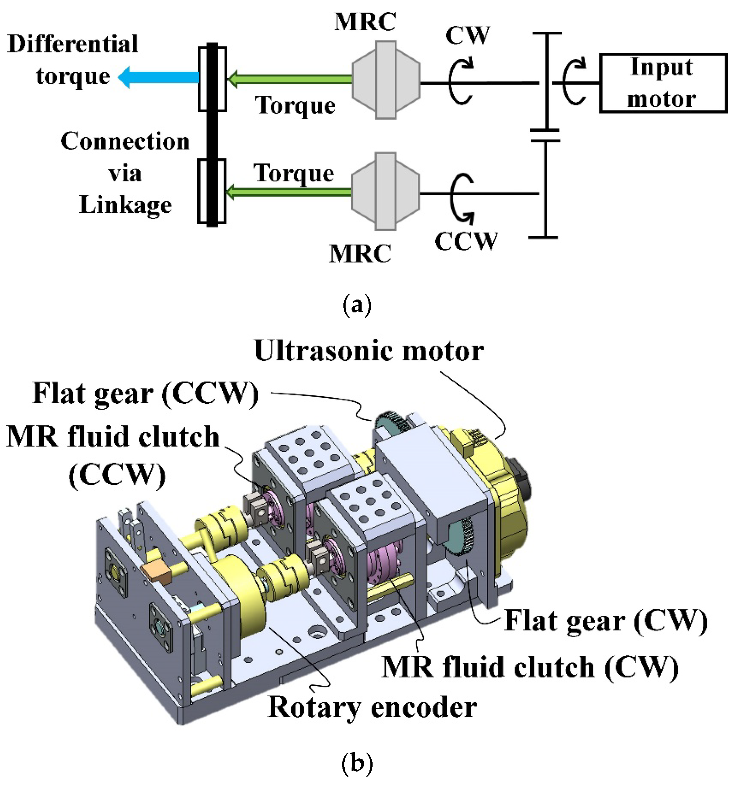
2. Twin-Driven Magnetorheological Fluid Actuator
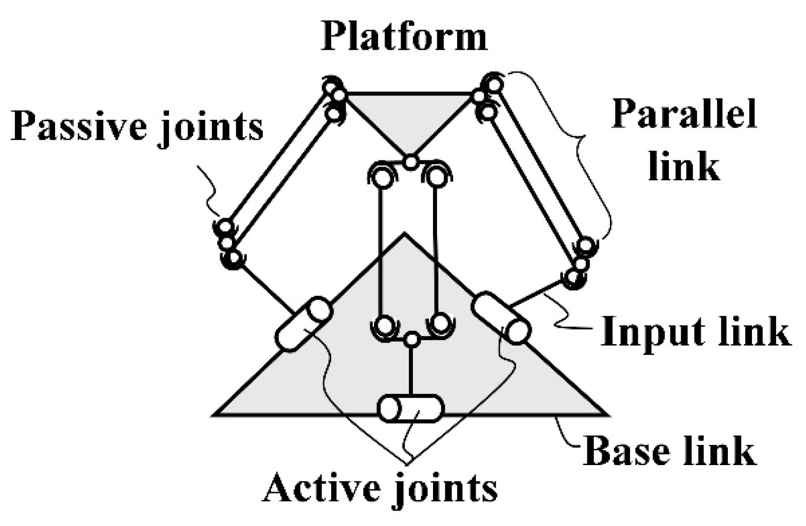
3. Design and Development of a Delta-Type Haptic Interface with MRA
3.1. Design
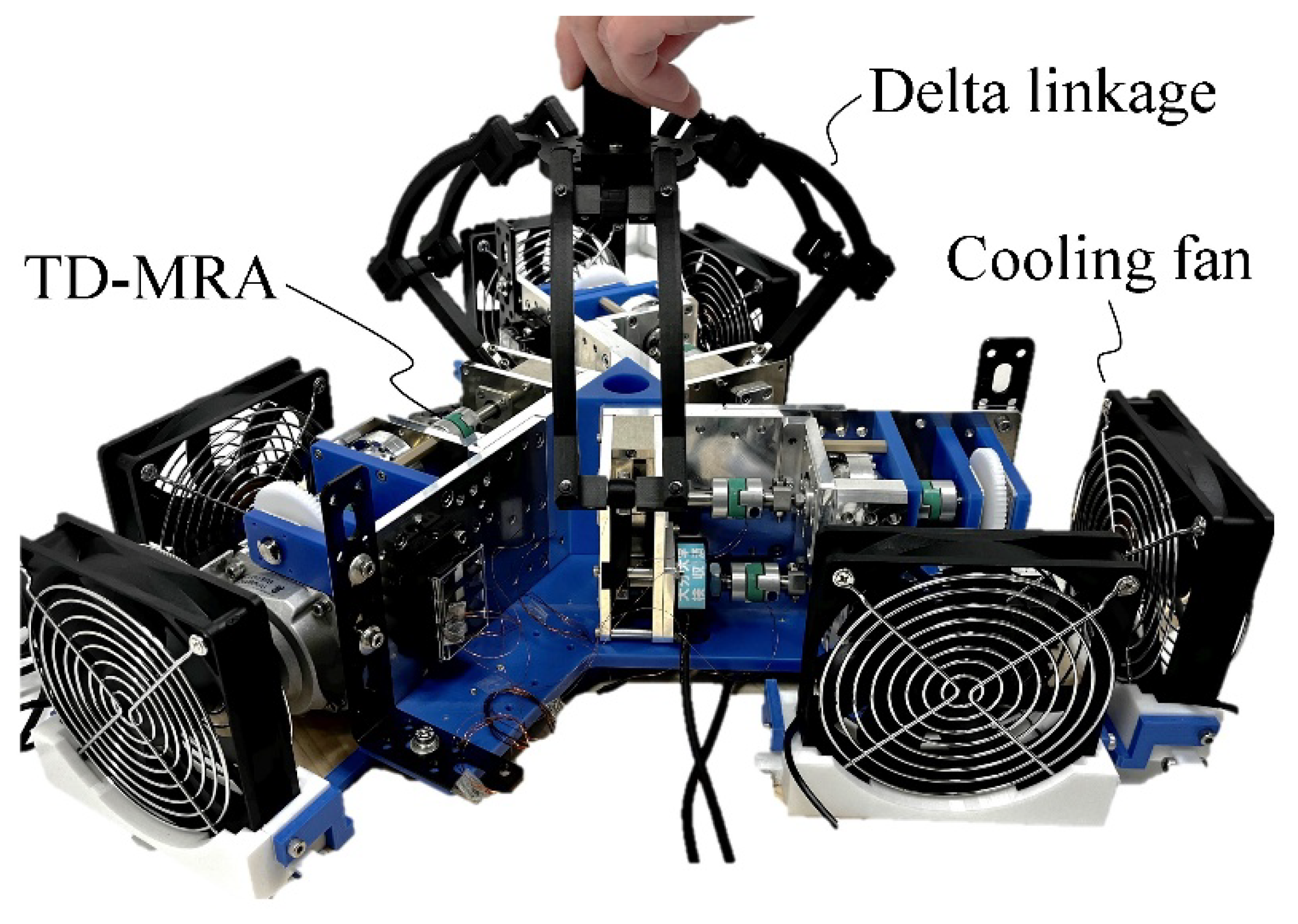
3.2. Development
4. Performance Validation with Open-Loop Force Controller
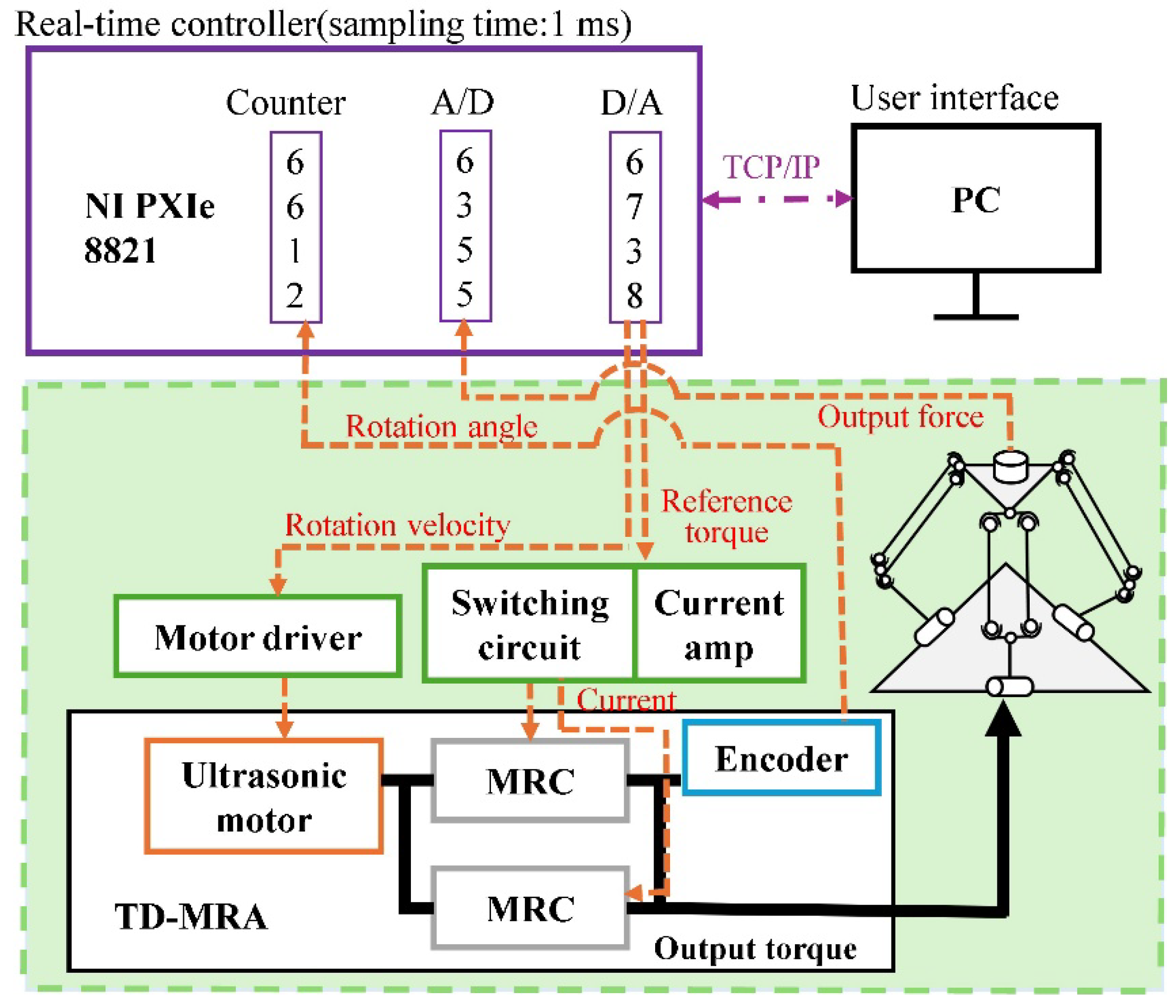
4.1. Measurement Setup
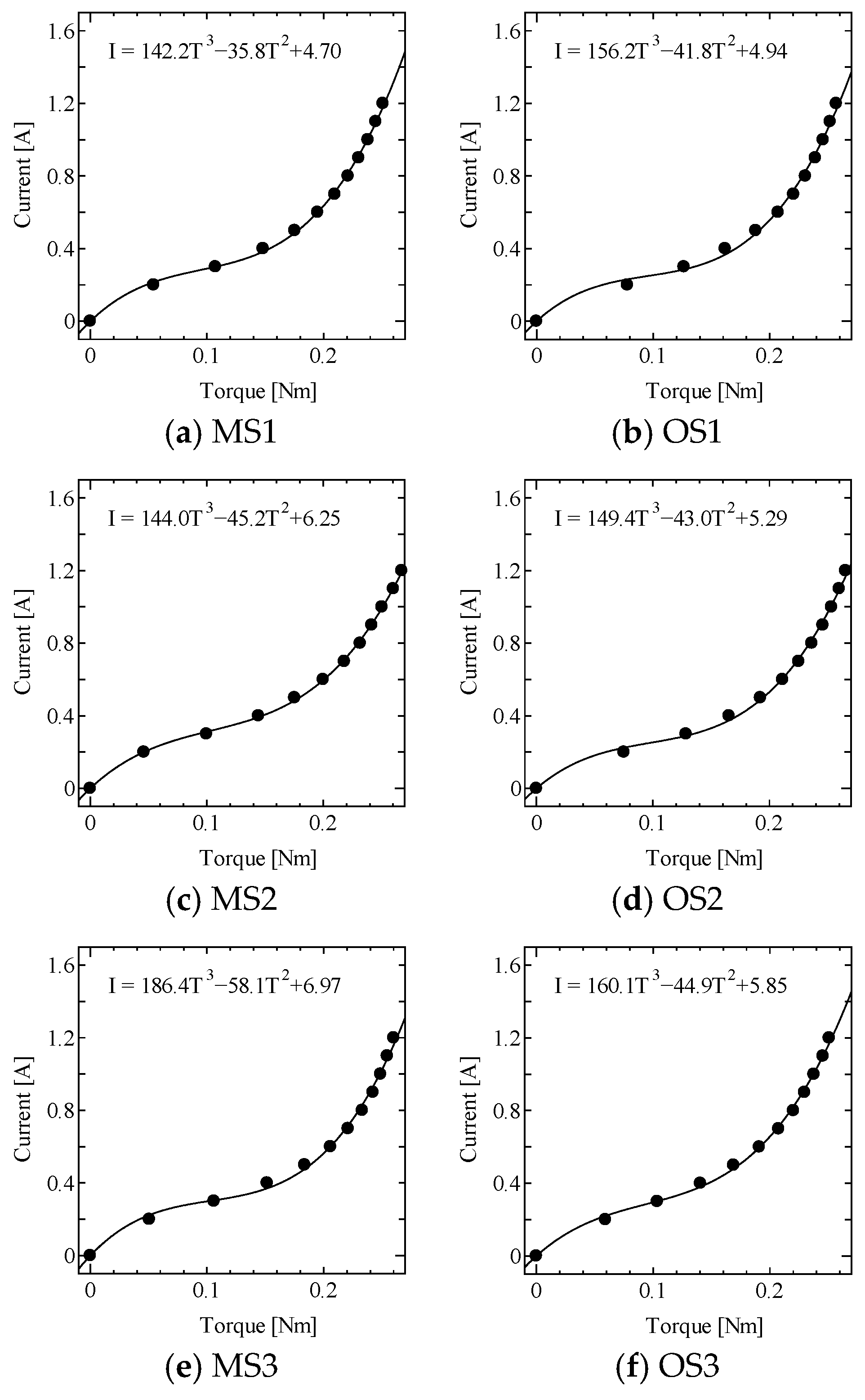
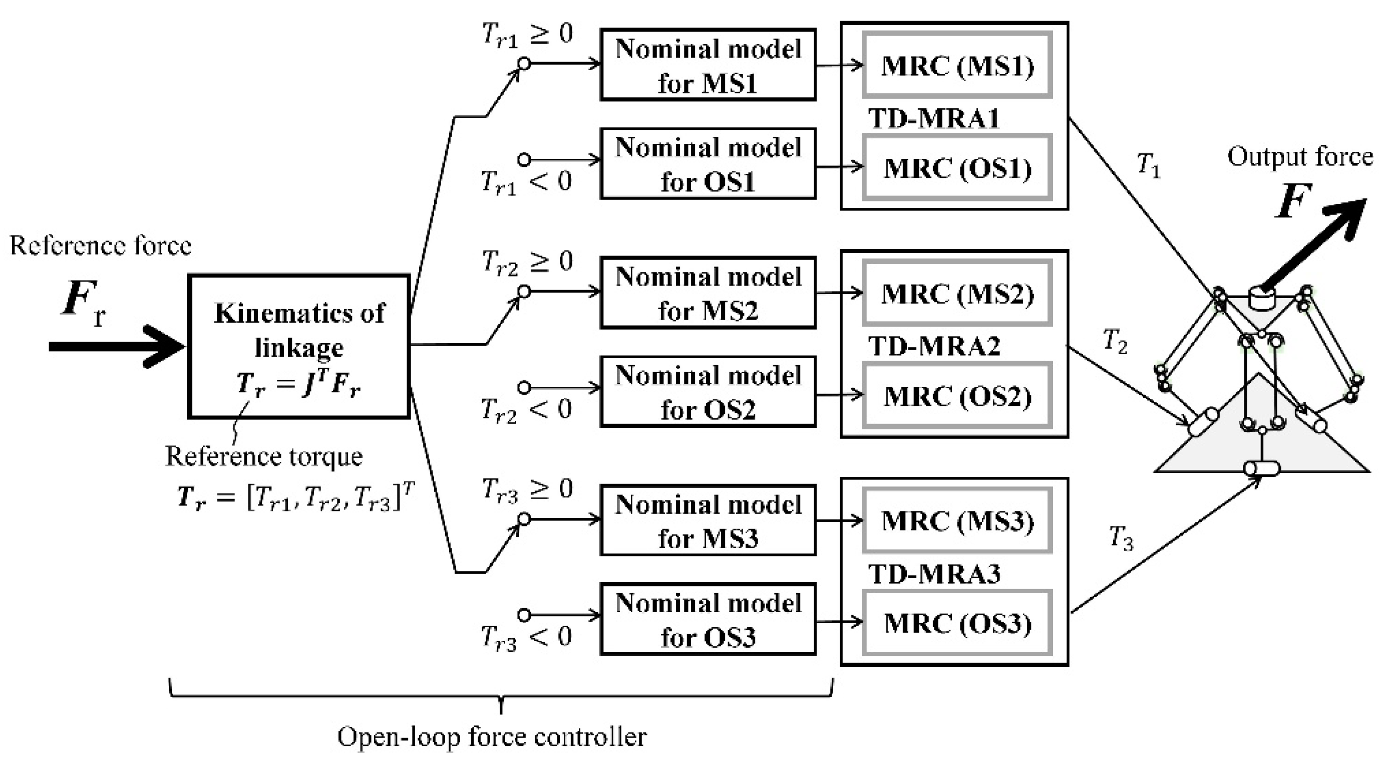
4.2. Design of the Open-Loop Controller
4.3. Experimental Conditions
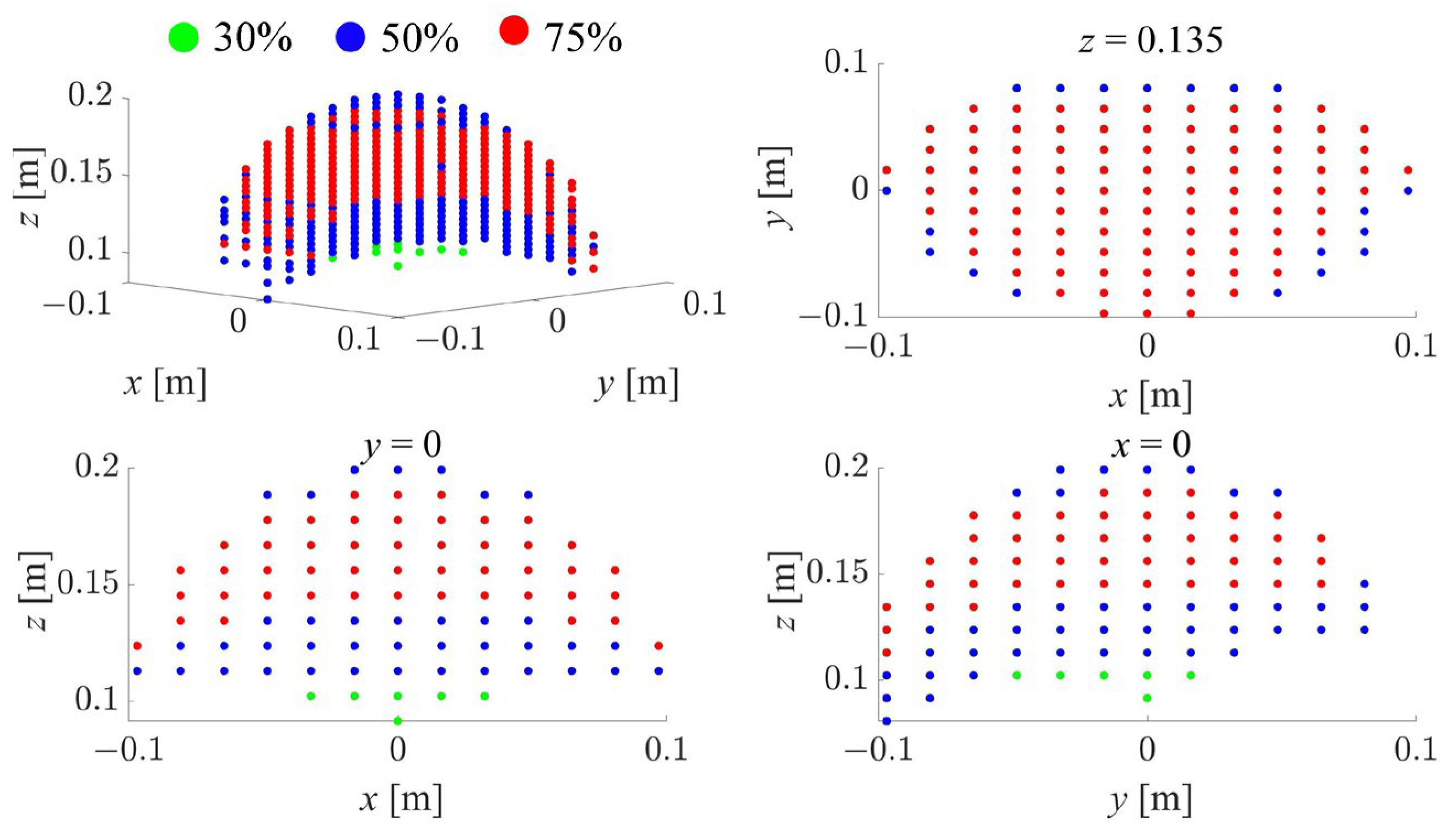
4.4. Results
4.5. Discussions
5. Conclusions
Author Contributions
Funding
Data Availability Statement
Conflicts of Interest
References
- Carlson, J.D.; Jolly, M.R. MR fluid, foam and elastomer devices. Mechatronics 2000, 10, 555–569. [Google Scholar] [CrossRef]
- Wang, X.; Gordaninejad, F. Study of magnetorheological fluids at high shear rates. Rheol. Acta 2006, 45, 899–908. [Google Scholar] [CrossRef]
- Becnel, A.C.; Sherman, S.; Hu, W.; Wereley, N.M. Nondimensional scaling of magnetorheological rotary shear mode devices using the Mason number. J. Magn. Magn. Mater. 2015, 380, 90–97. [Google Scholar] [CrossRef]
- Goncalves, F.D.; Carlson, J.D. Investigating the time dependence of the MR effect. Int. J. Mod. Phys. B 2007, 21, 4832–4840. [Google Scholar] [CrossRef]
- Scilingo, E.; Bicchi, A.; De Rossi, D.; Scotto, A. A magnetorheological fluid as a haptic display to replicate perceived biological tissues compliance. In Proceedings of the 1st Annual International IEEE-EMBS Special Topic Conference on Microtechnologies in Medicine and Biology. Proceedings (Cat. No.00EX451), Lyon, France, 12–14 October 2000; pp. 229–233. [Google Scholar]
- Bicchi, A.; Raugi, M.; Rizzo, R.; Sgambelluri, N. Analysis and design of an electromagnetic system for the characterization of magneto-rheological fluids for haptic interfaces. IEEE Trans. Magn. 2005, 41, 1876–1879. [Google Scholar] [CrossRef]
- Kikuchi, T.; Otsuki, K.; Furusho, J.; Abe, H.; Noma, J.; Naito, M.; Lauzier, N. Development of compact MR fluid clutch for human-friendly actuator. Adv. Robot. 2010, 24, 1489–1502. [Google Scholar] [CrossRef]
- Liu, G.; Gao, F.; Wang, D.; Liao, W.-H. Medical applications of magnetorheological fluid: A systematic review. Smart Mater. Struct. 2022, 31, 043002. [Google Scholar] [CrossRef]
- Zhang, P.; Kamezaki, M.; Otsuki, K.; He, S.; He, Z.; Dominguez, G.A.; Sugano, S. Development and evaluation of a backdrivable vane-type rotary actuator using magnetorheological fluids. IEEE/ASME Trans. Mechatron. 2022, 27, 4863–4873. [Google Scholar] [CrossRef]
- Najmaei, N.; Asadian, A.; Kermani, M.R.; Patel, R.V. Magneto-rheological actuators for haptic devices: Design, modeling, control, and validation of a prototype clutch. In Proceedings of the 2015 IEEE International Conference on Robotics and Automation (ICRA), Seattle, WA, USA, 26–30 May 2015; pp. 207–212. [Google Scholar]
- Ishida, T.; Takanishi, A. A Robot Actuator Development With High Backdrivability. In Proceedings of the 2006 IEEE Conference on Robotics, Automation and Mechatronics, Bangkok, Thailand, 1–3 June 2006; pp. 1–6. [Google Scholar]
- Kikuchi, T.; Abe, I.; Nagata, T.; Yamaguchi, A.; Takano, T. Twin-driven actuator with multi-layered disc MR fluid clutches for haptics. J. Intell. Mater. Syst. Struct. 2020, 32, 1326–1335. [Google Scholar] [CrossRef]
- Kikuchi, T.; Ikeda, A.; Matsushita, R.; Abe, I. Development of second prototype of twin-driven magnetorheological fluid actuator for haptic device. Micromachines 2024, 15, 1184. [Google Scholar] [CrossRef] [PubMed]
- Simorov, A.; Otte, R.S.; Kopietz, C.M.; Oleynikov, D. Review of surgical robotics user interface: What is the best way to control robotic surgery? Surg. Endosc. 2012, 26, 2117–2125. [Google Scholar] [CrossRef] [PubMed]
- Song, B.-K.; Oh, J.-S.; Choi, S.-B. Design of a new 4-dof haptic master featuring magnetorheological fluid. Adv. Mech. Eng. 2014, 6, 843498. [Google Scholar] [CrossRef]
- Siciliano, B.; Khatib, O. Handbook of Robotics, 2nd ed.; Section 43, Telerobotics; Springer: Berlin/Heidelberg, Germany, 2016; pp. 1085–1108. [Google Scholar]
- Williams, R.L., II. The Delta Parallel Robot: Kinematics Solutions. Internet Publication. 2016. Available online: https://people.ohio.edu/williams/html/PDF/DeltaKin.pdf (accessed on 22 January 2025).
- Pierrot, F.; Reynaud, C.; Fournier, A. DELTA: A simple and efficient parallel robot. Robotica 1990, 8, 105–109. [Google Scholar] [CrossRef]
- Ikeda, A.; Takano, T.; Abe, I.; Kikuchi, T.; Mimata, H.; Inomata, M. Kinematic analysis and evaluation of delta-type haptic device using twin-driven MR fluid actuator. In Proceedings of the 2023 IEEE/SICE International Symposium on System Integration (SII), Atlanta, GA, USA, 17–20 January 2023; pp. 76–81. [Google Scholar]
- Chen, W.-H. Disturbance Observer Based Control for Nonlinear Systems. IEEE/ASME Trans. Mechatronics 2004, 9, 706–710. [Google Scholar] [CrossRef]


| Parameters | Values |
|---|---|
| Length | 226 mm |
| Width | 106 mm |
| Height | 98 mm |
| Inertia of output shaft | 2.0 × 10⁻⁵ kg·m2 |
| Output torque | 0.25 Nm @ 1.2 A |
| Friction in off-state | 0.01 Nm (approximately) |
| Response time (time constant) | 10 ms (approximately) |
| Parameters | Values |
|---|---|
| Total diameter | 455 mm |
| Height of gripper | 181–330 mm |
| Radial range of motion | 80 mm |
| Vertical range of motion | >100 mm |
| Position [mm] | x | y | z |
|---|---|---|---|
| P0 | 0 | 0 | +134 |
| P1 | +60 | 0 | +134 |
| P2 | 0 | −60 | +134 |
| P3 | 0 | 0 | +189 |
| P4 | 0 | 0 | +104 |
| Error [N] | Fx | Fy | Fz | Ave. |
|---|---|---|---|---|
| P0 | 0.08 | 0.15 | 0.10 | 0.11 |
| P1 | 0.07 | 0.16 | 0.13 | 0.12 |
| P2 | 0.13 | 0.35 | 0.19 | 0.22 |
| P3 | 0.02 | 0.12 | 0.21 | 0.12 |
| P4 | 0.12 | 0.21 | 0.14 | 0.16 |
| Ave. | 0.08 | 0.20 | 0.15 | 0.15 |
Disclaimer/Publisher’s Note: The statements, opinions and data contained in all publications are solely those of the individual author(s) and contributor(s) and not of MDPI and/or the editor(s). MDPI and/or the editor(s) disclaim responsibility for any injury to people or property resulting from any ideas, methods, instructions or products referred to in the content. |
© 2025 by the authors. Licensee MDPI, Basel, Switzerland. This article is an open access article distributed under the terms and conditions of the Creative Commons Attribution (CC BY) license (https://creativecommons.org/licenses/by/4.0/).
Share and Cite
Kikuchi, T.; Ikeda, A.; Abe, I. Design and Performance Evaluation with an Open-Loop Force Controller for a Delta-Type Haptic Device with Magnetorheological Fluid Actuator. Actuators 2025, 14, 122. https://doi.org/10.3390/act14030122
Kikuchi T, Ikeda A, Abe I. Design and Performance Evaluation with an Open-Loop Force Controller for a Delta-Type Haptic Device with Magnetorheological Fluid Actuator. Actuators. 2025; 14(3):122. https://doi.org/10.3390/act14030122
Chicago/Turabian StyleKikuchi, Takehito, Asaka Ikeda, and Isao Abe. 2025. "Design and Performance Evaluation with an Open-Loop Force Controller for a Delta-Type Haptic Device with Magnetorheological Fluid Actuator" Actuators 14, no. 3: 122. https://doi.org/10.3390/act14030122
APA StyleKikuchi, T., Ikeda, A., & Abe, I. (2025). Design and Performance Evaluation with an Open-Loop Force Controller for a Delta-Type Haptic Device with Magnetorheological Fluid Actuator. Actuators, 14(3), 122. https://doi.org/10.3390/act14030122