Article

Design of Automatic Landing System for Carrier-Based Aircraft Based on Adaptive Fuzzy Sliding-Mode Control

Department of Aeronautics and Astronautics, Fudan University, Shanghai 200433, China
*
Author to whom correspondence should be addressed.
Actuators 2025, 14(3), 114; https://doi.org/10.3390/act14030114
Submission received: 20 December 2024 / Revised: 14 January 2025 / Accepted: 25 February 2025 / Published: 26 February 2025
(This article belongs to the Section Aerospace Actuators)

Abstract

:
Carrier-based aircraft (CBA) landing involves complex system engineering characterized by strong non-linearity, significant coupling and susceptibility to environmental disturbances. To address uncertainties in parameters, carrier air-wake disturbances and other challenges inherent to CBA landing, this paper presents a longitudinal automatic landing system based on adaptive fuzzy sliding-mode control. This system was developed to improve control accuracy and stability during the critical landing phase. Furthermore, this paper analyzes components of carrier air-wake and motion conditions for ideal landing points on the carrier deck, and designs a sliding-mode surface with the integral term. An adaptive fuzzy sliding-mode controller based on equivalent and switching controls is constructed, which exhibits stability under the Lyapunov stability condition. Moreover, a Monte Carlo simulation method is employed to verify the simulation of the automatic landing control system. Owing to its impressive dynamic performance and robustness, the proposed control method can track expected values with high accuracy in a complex environment, thereby satisfying the CBA landing requirements.

1. Introduction

Carrier-based aircraft (CBA) landing technology has long presented a bottleneck to improving its compatibility with aircraft carriers. This technology plays an important role in advancing maritime military equipment, guaranteeing the safety of aircraft pilots, relieving the burden of landing operations and improving the efficiency of military operations [1,2,3]. Contrary to that in general landing, the CBA needs to fly along a relative glide path in a complex environment due to disturbances such as carrier air wake and carrier deck motion. Furthermore, it requires high landing accuracy because of an extremely narrow landing area [4,5]. In addition, the CBA usually remains in the velocity instability domain in terms of velocity during landing and exhibits a low flight dynamic pressure, causing sensitivity to wind disturbances [6,7]. Thus, CBA landing control is a problem of high-accuracy tracking for the glide path and stable control under low dynamic pressure. The difficulties to achieve this mainly include the following three aspects:
  • Complex external disturbances. Disturbances such as carrier air wake and constant wind affect CBA landing. In addition, because the CBA exhibits heightened sensitivity to wind disturbances due to its flight conditions, which are characterized by a high angle of attack and low dynamic pressure, its controller must exhibit a strong capacity to prevent wind disturbance.
  • Nonlinear coupling and parameter uncertainty. The controller must be able to overcome matching uncertainty and nonlinear coupling, particularly when the CBA exhibits a strong nonlinear coupling feature amid considerable alterations in flight conditions.
  • Weak self-stabilization of velocity. During landing, the CBA stays in the instability domain in terms of its velocity and maintains continuous instability without any control action, causing inaccurate tracking of its landing trajectory. Therefore, the power compensation system must be studied to compensate for velocity deviation via thrust adjustment.
Improving the success rate of CBA landing has been a global challenge and a research hot spot among scholars. Early landing control technology primarily adopted the typical control method [8,9,10]. However, the general control method could not achieve satisfactory landing performance for the CBA in a complex landing environment. Therefore, scholars have proposed several improvement methods based on modern control theory [11,12,13,14,15]. Yu et al. designed a robust adaptive landing attitude control law [16] and estimated the carrier air-wake disturbance using a nonlinear state observer, effectively improving the adaptive capacity of the controller with object uncertainty and external disturbance problems. However, the research was performed using a small disturbance-linearized model without considering the nonlinear characteristics of the object. Luo and Guan et al. designed internal and external control loops and a power compensation system for the automatic landing system using the nonlinear dynamic inverse method, realizing accurate control under the error disturbance [17,18]. However, the nonlinear dynamic inverse control method could not solve the high dependency on the model and completely eliminated the dynamic information of the system itself, causing errors and subsequently resulting in the low stability and robustness of the closed-loop control system. To solve the uncertain error disturbance of the CBA, Subrahmanyam applied the H robust control strategy to design a fully automatic landing system for an F/A-18A CBA [19]. The design was intended for maintaining a constant glide path under the effect of vertical gust and sensor noise during CBA landing and ensuring that the system can respond well to the vertical rate instruction. However, if the high-order transfer function was involved, the high-order system would be more complex when the H control strategy was applied. Zhang et al. designed a flight control system with adaptive control for managing the fault conditions of aircraft [20]. The simulation results revealed that the adaptive controller could adjust the flight path better under the fault conditions of the aircraft in the design compared to the general design. However, the adaptive control exhibited an extremely considerable defect because the controller parameters could not be adjusted in a timely manner when the nonlinear model exhibited any obvious changes. Therefore, adaptive control is generally used in combination with robust control, inverse control, sliding-mode control, etc. [21].
Sliding-mode control is a highly effective nonlinear strategy within variable structure control. It achieves robust system control through a variable structure-control strategy. The essence of this strategy lies in designing a sliding surface, also known as a switching surface, which is a subset of the state space typically defined by a linear combination of state variables. The control objective is to make the state trajectory reach the sliding surface and slide along it to the desired equilibrium state. Sliding-mode control involves switching control variables to make the system slide along the sliding surface, maintaining invariance despite parameter perturbations and external disturbances. Depending on such characteristics, sliding-mode control has been widely applied in the design of flight control systems [22,23,24,25,26]. Xue et al. designed an automatic landing controller for aircraft with sliding-mode control. The method transformed the deviation of the spatial position relative to the ideal flight path into a state variable and built a sliding-mode function. The simulation results revealed that the design could ensure accurate tracking of the ideal glide path during aircraft landing [27]. Zhu et al. designed an automatic landing controller in combination with a neural network in sliding-mode control. This design could not only effectively improve the anti-disturbance performance of the automatic landing system but also realize safe guidance for aircraft landing in severe environments [28,29]. SMC’s robustness to disturbances makes it highly effective in handling significant external perturbations such as carrier air-wake and deck motion, ensuring stable and accurate landing trajectories. Its ability to switch control structures allows it to manage the nonlinear dynamics of CBAs, adapting to varying flight conditions and disturbances. One of the key benefits of SMC is its finite-time convergence, which ensures rapid corrections in the flight path, which are critical for the high-precision requirements of CBA landing. However, a major drawback of the traditional SMC is chattering, which refers to high-frequency oscillations in the control input. This can cause mechanical wear and tear and reduce the accuracy and stability of the control system. Additionally, the discontinuous nature of the control law requires sophisticated hardware and software to manage the high-frequency switching, increasing the implementation complexity and cost.
To address these limitations, this paper proposes an Adaptive Fuzzy Sliding-Mode Control (AFSMC) approach based on the CBA nonlinear model. AFSMC integrates fuzzy logic with SMC to smooth control actions and mitigate chattering, while adaptive control adjusts parameters in real time, enhancing robustness against disturbances and uncertainties. The approach involves the following key components:
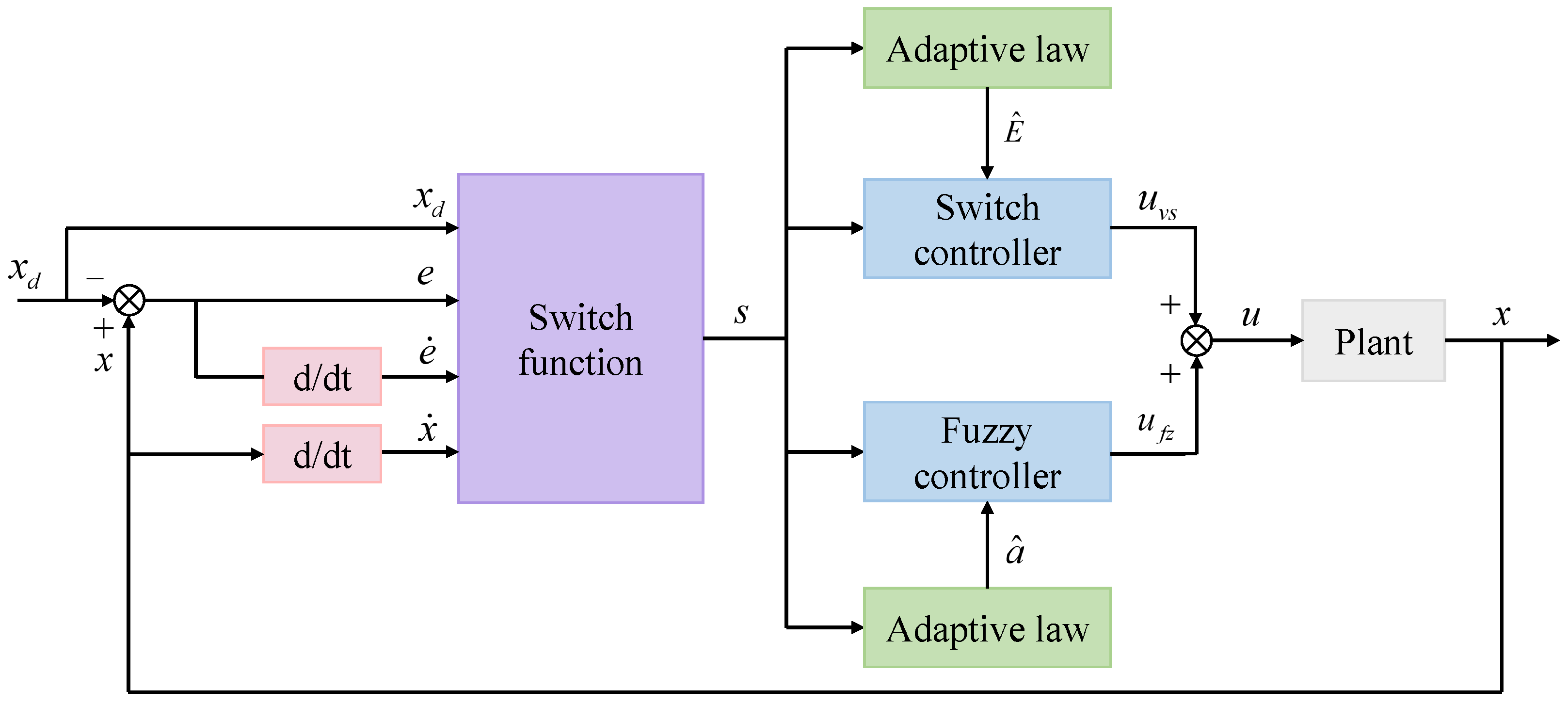
  • Sliding-Mode Surface: A predefined trajectory in the state space that the system state is driven towards. Once the system state reaches this surface, it is forced to remain on it, ensuring the desired system behavior.
  • Fuzzy Controller: Reduces the complexity of the control system by minimizing the number of fuzzy rules required. The fuzzy controller processes the sliding-mode switching function to produce smooth control actions.
  • Adaptive Mechanism: Continuously adjusts control parameters in real-time based on the current state of the system and external disturbances. This ensures that the controller remains effective even as system parameters change, enhancing robustness and performance.
The primary contribution of this paper lies in the development of an AFSMC system that effectively manages non-linear coupling and parameter uncertainties through real-time adjustments of control parameters. By integrating the sliding-mode switching function into the fuzzy controller, the number of fuzzy rules is significantly reduced, simplifying the control system design. This results in a control strategy that not only improves accuracy and stability but also mitigates the chattering problem inherent to traditional SMC. The AFSMC effectively manages non-linear coupling and parameter uncertainties through the real-time adjustments of control parameters. This is achieved by combining the robustness of sliding-mode control with the flexibility of fuzzy logic and adaptive mechanisms, ensuring high accuracy in tracking the desired flight path even under significant disturbances. By integrating the sliding-mode switching function into the fuzzy controller, the number of fuzzy rules is significantly reduced. This simplification lowers the computational complexity and makes the control system more practical for real-time applications, facilitating easier implementation and maintenance in engineering applications. The AFSMC demonstrates superior performance in maintaining control accuracy and stability during critical landing phases. This is particularly important in environments with significant disturbances, where traditional methods may fail to deliver consistent performance. The adaptive nature of the control strategy allows it to respond dynamically to changes in the environment, ensuring reliable operation. The incorporation of fuzzy logic into the AFSMC significantly reduces the chattering problem inherent to traditional sliding-mode control. This leads to smoother control actions and less wear and tear on mechanical components, enhancing the longevity and reliability of the control system.
The paper is organized as follows: Section 2 describes the nonlinear dynamic model of the carrier-based UAV, carrier air-wake model and motion model of the carrier deck; Section 3 presents the detailed design of the adaptive fuzzy sliding-mode controller; Section 4 describes the automatic landing control system based on AFSMC; Section 5 presents the simulation results on the effectiveness of the designed controller and Section 6 presents the conclusions.

2. Problem Formulation

2.1. Nonlinear Dynamic Model of CBA

Multiple simulations reveal that atmospheric disturbance affects the CBA primarily due to path errors in the vertical direction resulting from vertical disturbance components [30]. Therefore, the current research only studies the longitudinal flight path control of the CBA and develops a standard longitudinal nonlinear mathematical model for a type of CBA as follows:
V ˙ = δ T T max m cos α ρ V 2 S w 2 m C D 0 + C D α 2 α 2 g sin γ α ˙ = δ T T max m V sin α ρ V S w 2 m C L 0 + C L α α + C L δ e δ e       + q + g V sin α sin θ + cos α cos θ θ ˙ = q q ˙ = ρ V 2 S w c A 2 I y y C m 0 + C m α α + C m q q c A 2 V + C m δ e δ e H ˙ = V sin γ
where V , α , θ , q , γ and H represent the airspeed, angle of attack, angle of pitch, rate of pitch, track angle and altitude, respectively; I y y represents the rotational inertia along the pitch axis; m and g represent the mass and gravitational acceleration, respectively; ρ represents the air density; S w represents the wing reference area; c A represents the mean aerodynamic chord of the wing; δ T represents the degree of opening of the accelerator; T m a x represents the maximum engine thrust; δ e represents the elevator deflection angle; and C L 0 , C L α , C L δ e , C D 0 , C D α 2 , C m 0 , C m α , C m q and C m δ e represent aerodynamic coefficients.

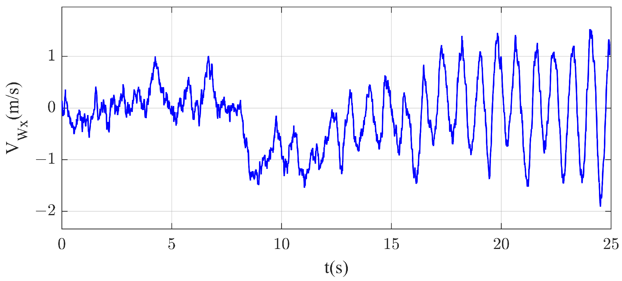
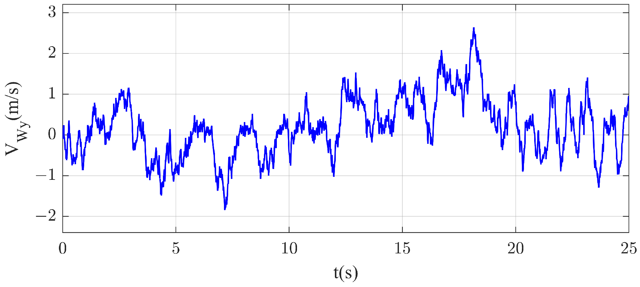
2.2. Carrier Air-Wake Model

The carrier air wake, which is the airflow field at the tail of the naval ship, is an important source of the dispersion error of the landing point for CBAs. According to USN standard MIL-F-8785C [31], the carrier air wake comprises four components: the random free atmospheric turbulence including u 1 , v 1 and w 1 [32,33]; the steady-state component of the carrier air wake including u 2 and w 2 ; the periodic component of the carrier air wake including u 3 and w 3 ; and the random disturbance component of the carrier air wake including u 4 , v 4 and w 4 .
V W x = u 1 + u 2 + u 3 + u 4 V W y = w 1 + w 2 + w 3 + w 4 V W z = v 1 + v 4
The random free atmospheric turbulence is independent of the position of the carrier-based aircraft during the landing process. Therefore, the transfer function of the random free atmospheric turbulence is derived from the Dryden spatial spectrum and the established landing-related standards; the USN standard MIL-F-8785C describes the steady-state component of the carrier air wake using a piecewise function; similarly, USN standard MIL-F-8785C provides a mathematical model for the periodic component of the carrier air wake; and the random disturbance component of the carrier air wake can be represented by a white noise shaping filter. Figure 1 and Figure 2 depict the comprehensive simulation results of the carrier air wake, where V W x and V W y represent components of the wind speed in the x-axis and y-axis, respectively. The x-axis forward and the y-axis downward are defined as ‘positive’, which are located in the longitudinal plane of approaching and landing of the CBA. The maximum amplitudes are ∼1.9 m/s and ∼2.6 m/s for the horizontal and vertical components, respectively.

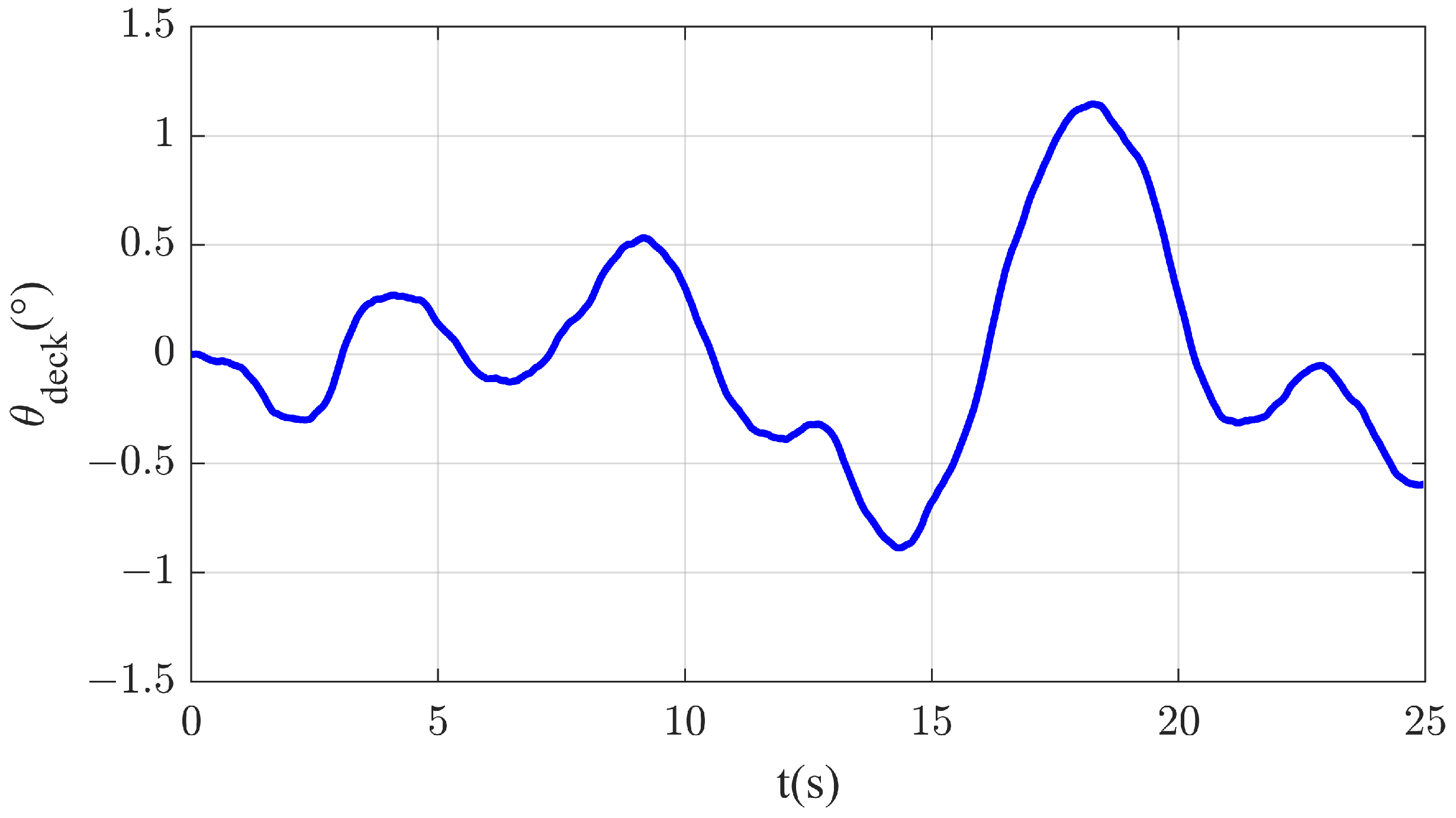
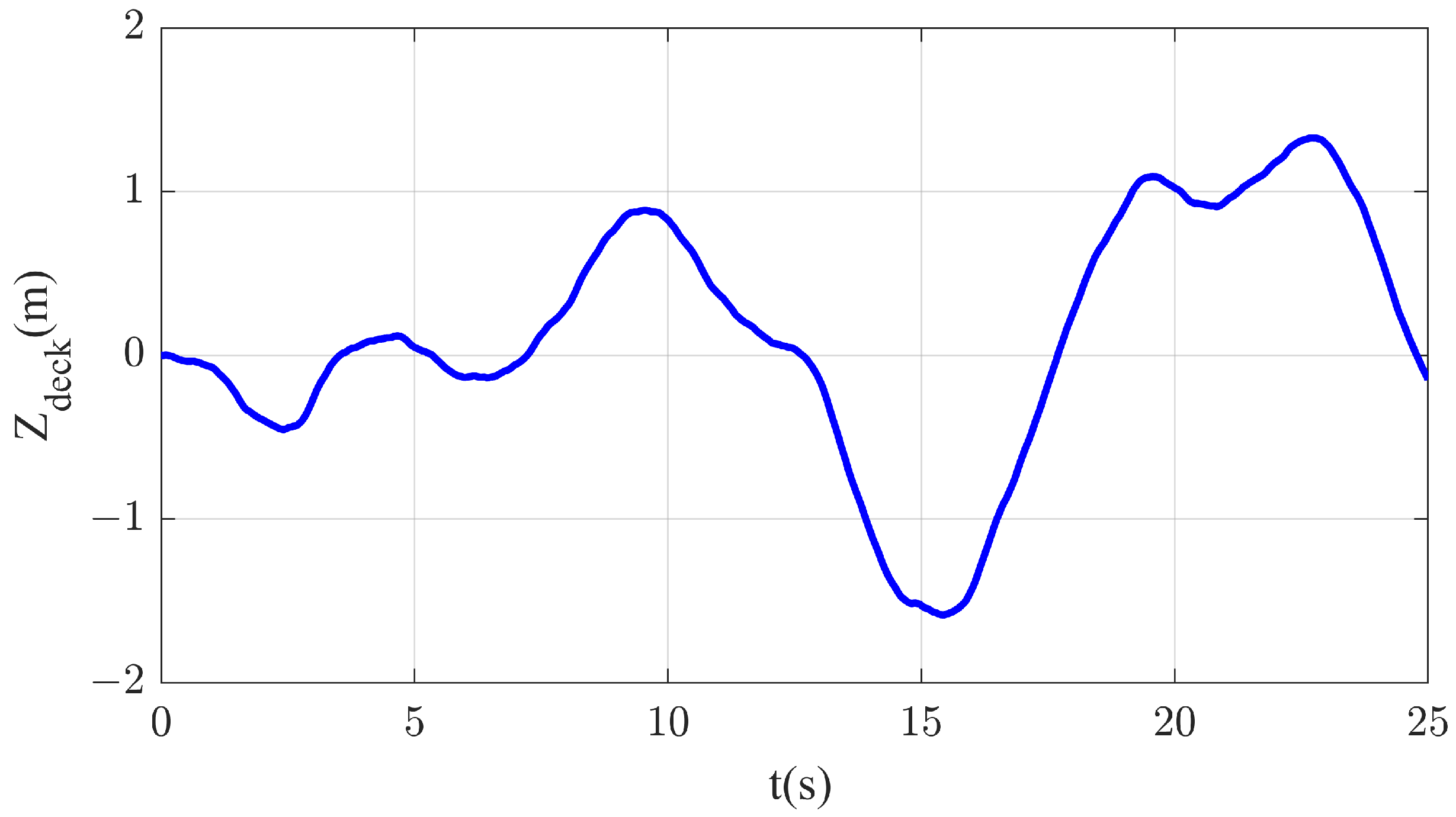
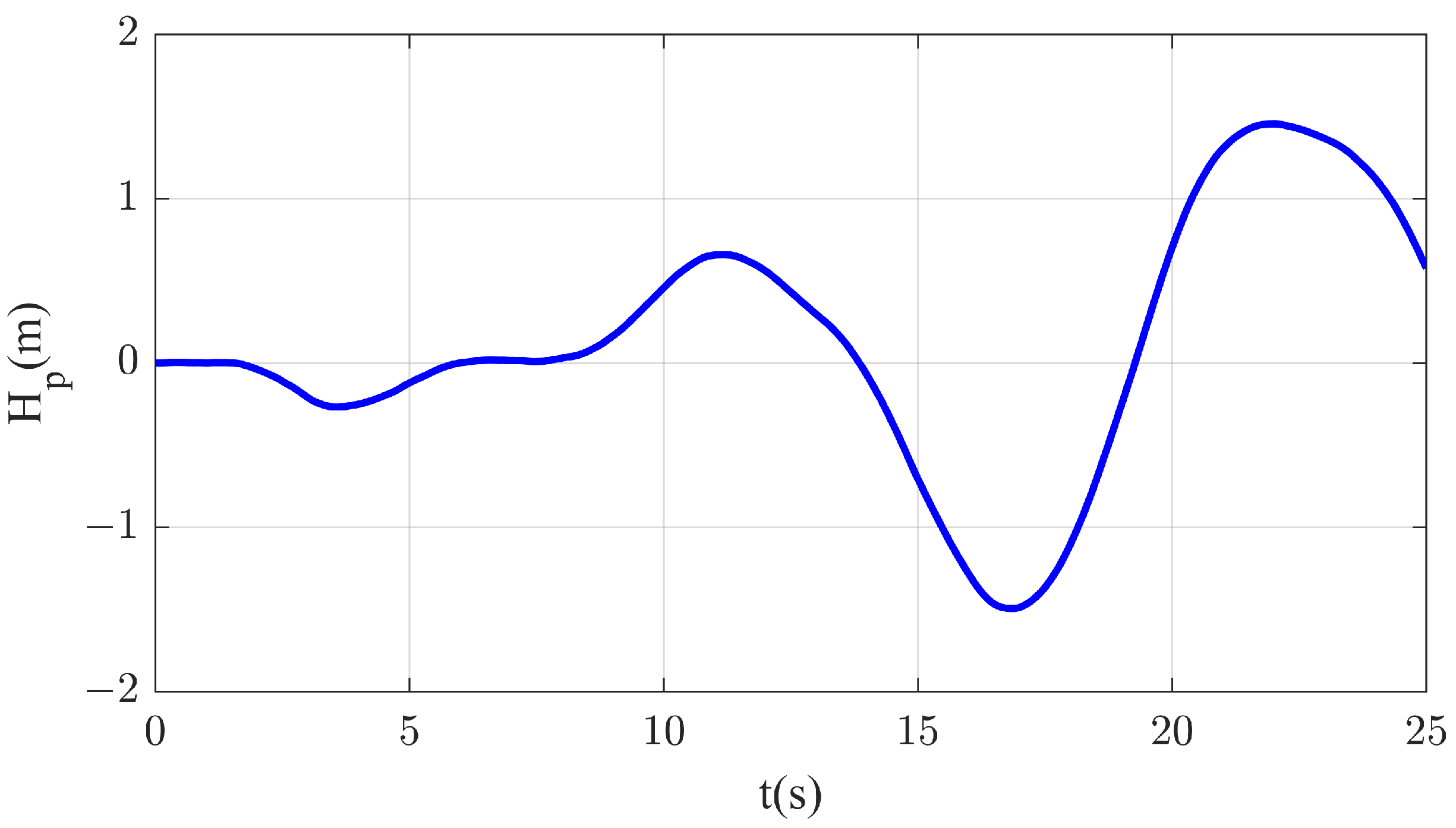
2.3. Motion Model of the Carrier Deck

The motion amplitude and frequency of the carrier deck are relevant to the sea state. The general sea wave primarily induces a pitching motion with a short cycle, while the ground swell primarily triggers a heaving motion with a long cycle. When acquiring the motion information of the carrier deck, a common approach involves constructing a power spectral density function. This function is established based on the data collected from the sea waves and wind, allowing for the subsequent simplification of the curve of the constructed power spectral density function. This simplification facilitates the derivation of the transfer function for the modeling filter. In this research, the motion information of the carrier deck is represented by the product of the modeling filter corresponding to the white noise and power spectrum, while the transfer functions of the heaving and the pitch angle of the carrier deck in the longitudinal channel and the white noise are expressed as Equations (3) and (4) [34]. The simulation results are presented in Figure 3 and Figure 4.
θ d e c k N W = 0.334059 s 2 s 4 + 0.604 s 3 + 0.79658 s 2 + 0.2062 s + 0.124
Z d e c k N W = 0.353568 s 2 + 0.01414 s s 4 + 0.38 s 3 + 0.4977 s 2 + 0.0836 s + 0.0484
where N W represents the white noise, and θ d e c k and Z d e c k are the heaving of the carrier deck and the pitch angle, respectively.
The altitude variation H p of the ideal landing point is related to the pitching motion θ d e c k and heaving motion Z d e c k of the carrier deck, which can be expressed as follows:
H p = Z d e c k + θ d e c k L T D
where L T D is the longitudinal–horizontal distance between the ideal landing point and the pitching center of the aircraft carrier. The curve of the altitude variation of ideal landing points on the carrier deck is shown in Figure 5.

3. Design of the Adaptive Fuzzy Sliding-Mode Controller

3.1. Fuzzy Approximation Theorem

A fuzzy system typically consists of four components: fuzzification, fuzzy rules, fuzzy inference and defuzzification. The purpose of fuzzification is to convert input variables into corresponding membership functions, which represent the degree of fuzziness of the inputs. Fuzzy rules are usually composed of IF–THEN statements that describe the relationships between inputs and outputs. Fuzzy inference, as the core of the fuzzy controller, utilizes fuzzy inference methods to perform reasoning operations based on the fuzzified input variables and fuzzy rules, thereby generating fuzzy output results. The defuzzification process then converts these fuzzy output results into specific, clear output values.
The fuzzy system has a universal approximation characteristic [35,36] so that the switching function s in the sliding-mode control is considered an input of the fuzzy controller, while the control input u is considered an output of the fuzzy system to constitute a single input/output fuzzy system and further create a rule database for the fuzzy system according to the experiment. Compared to the traditional controller, the input fuzzy controller can greatly decrease the number of fuzzy rules. To ensure s = 0 , the fuzzy rule of the fuzzy controller is represented as follows:
Rule i : IF s is F s i THEN u is α i
where F s i and α i i = 1 , 2 , . . . , m are the input and output fuzzy sets, respectively.
If the centroid method is used for defuzzification, the controller output is obtained as follows:
u f z s = i = 1 m w i × α i i = 1 m w i
where w i is the weight of the ith fuzzy rule.

3.2. Design of the Controller

Consider the following second-order system:
x ¨ = f x , x ˙ + g x , x ˙ u + d ( t )
where d is the external disturbance.
The tracking error can be defined as follows:
e ( t ) = x ( t ) x d ( t )
where x d is the expected state.
The integral sliding-mode surface is defined as follows:
s = x ˙ ( t ) 0 t x ¨ d ( τ ) k 1 e ˙ ( τ ) k 2 e ( τ ) d τ
where k 1 and k 2 are positive constant coefficients.
According to the derivation for the sliding-mode function:
s ˙ = x ¨ ( t ) x ¨ d ( t ) + k 1 e ˙ ( t ) + k 2 e ( t ) = e ¨ ( t ) + k 1 e ˙ ( t ) + k 2 e ( t )
if the system is in an ideal sliding-mode control state, then s = s ˙ = 0 , and thus
e ¨ ( t ) + k 1 e ˙ ( t ) + k 2 e ( t ) = 0
If the selected coefficients k 1 and k 2 satisfy the Hurwitz criterion, then all characteristic roots of the error system possess negative real parts, which implies that the system can converge. If f x , x ˙ , g x , x ˙ and d ( t ) are known, according to Equations (8) and (10), the control law is obtained as follows:
u * = g x , x ˙ 1 ( f ( x , x ˙ ) d ( t ) + x ¨ d ( t ) k 1 e ˙ ( t ) k 2 e ( t ) )
If f x , x ˙ , g x , x ˙ and d ( t ) are unknown, and u * cannot be realized, the fuzzy approximation method can be used to approximate the ideal control law u * . To achieve better approximation performance, the selection of the fuzzy rules output α is crucial. Let α i be an adjustable parameter and ξ be a fuzzy base vector; then, the output of fuzzy system Equation (7) changes to:
u f z s , α = α T ξ
where α = [ α 1 , α 2 , , α m ] T , ξ = [ ξ 1 , ξ 2 , , ξ m ] T , ξ i = w i / i = 1 m w i .
According to the fuzzy approximation theorem, an optimal fuzzy system u f z s , α * exists for approximating u * :
u * = u f z s , α * + ε = α * T ξ + ε
where ε is the approximate error satisfying ε E , where E is the gain of the switching term.
In fact, since it is difficult to accurately obtain the optimal output α * , the control input u * is approximated by estimating the fuzzy system’s output α ^ . If the fuzzy system u f z is used to approximate u * , then
u f z s , α ^ = α ^ T ξ
Additionally, the switching control law u v s can be employed to compensate for the deviation between u * and u f z , and then the total control law is:
u = u f z + u v s
The structure of the AFSMC is shown in Figure 6.
According to Equation (15),
u ˜ f z = u ^ f z u * = u ^ f z u f z * ε
If α ˜ = α ^ α * is defined, then Equation (18) can be changed to
u ˜ f z = α ˜ T ξ ε
According to Eqautions (11)–(13), the ideal computational controller is as follows:
u * = g x , x ˙ 1 f x , x ˙ d x ¨ d + e ¨ s ˙ = g x , x ˙ 1 f x , x ˙ d + x ¨ s ˙ = g x , x ˙ 1 g x , x ˙ u s ˙
According to Eqautions (17) and (20), the reaching law for fuzzy sliding-mode control can be expressed as:
s ˙ = g x , x ˙ u u * = g x , x ˙ u f z + u v s u *
The following fuzzy system adaptive law and switching control are used:
α ˜ ˙ = α ^ ˙ = η 1 s ξ
u v s = E sgn s
where η 1 is a positive real constant, and sgn s is the sign function of the sliding surface s. The sign function is defined as follows:
sgn ( s ) = { 1 i f   s > 0 1 i f   s < 0 0 i f   s = 0
Theorem 1.
Assuming that E is a positive constant, if the adaptive law Equation (21) and switching control Equation (22) are employed, the tracking error can converge to zero within a finite time.
Proof. 
The Lyapunov function is defined as follows:
V 1 = 1 2 s 2 + g x , x ˙ 2 η 1 α ˜ T α ˜
According to the derivation for V 1 ,
V ˙ 1 = s s ˙ + g x , x ˙ η 1 α ˜ T α ˜ ˙ = s g x , x ˙ u f z + u v s u * + g x , x ˙ η 1 α ˜ T α ˜ ˙ = s g x , x ˙ u ˜ f z + u v s + g x , x ˙ η 1 α ˜ T α ˜ ˙ = s g x , x ˙ α ˜ T ξ ε + u v s + g x , x ˙ η 1 α ˜ T α ˜ ˙ = g x , x ˙ α ˜ T s ξ + 1 η 1 α ˜ ˙ + s g x , x ˙ u v s ε
The design of Equation (21) ensures that the first term on the right-hand side of Equation (26) is zero. Substituting Equations (21) and (22) into Equation (25) yields:
V ˙ 1 = E s g x , x ˙ ε s g x , x ˙ E s g x , x ˙ + ε s g x , x ˙ = E ε s g x , x ˙
Since ε E , it follows that V ˙ 1 0 . The proof is completed. □
Given the difficulty in determining the switching gain E in the switching controller, it is usually determined according to the experiment in the actual control. If E is large, large buffeting may occur; otherwise, the control system may be unstable. Therefore, in this paper, we replace E with an estimated gain of switching term E ^ and adjust the estimated gain through a switching control adaptive law. By designing a reasonable switching control adaptive law, we can better mitigate buffeting phenomena and ensure the stability of the system. Hence, Equation (22) is changed to:
u v s = E ^ sgn s
The following switching control adaptive law is used:
E ^ ˙ = η 2 s
Theorem 2.
If the switching control adaptive law Equation (28) is employed, the designed closed-loop system is stable.
Proof. 
The estimated gain error of the switching term is defined as E ˜ = E ^ E , and the Lyapunov function of the closed-loop system is defined as follows:
V 2 = V 1 + g x , x ˙ 2 η 2 E ^ 2
where η 2 is a positive real constant.
According to the derivation for V 2 ,
V ˙ 2 = s s ˙ + g x , x ˙ η 1 α ˜ T α ˜ ˙ + g x , x ˙ η 2 E ˜ E ˜ ˙ = g x , x ˙ α ˜ T s ξ + 1 η 1 α ˜ ˙ + s g x , x ˙ u v s ε + g x , x ˙ η 2 E ˜ = E ^ s g x , x ˙ ε s g x , x ˙ + g x , x ˙ η 2 E ^ E E ^ ˙
Substituting Equations (28) into Equation (25) yields:
V ˙ 2 = E ^ s g x , x ˙ ε s g x , x ˙ + g x , x ˙ E ^ E s = ε s g x , x ˙ E s g x , x ˙ ε s g x , x ˙ E s g x , x ˙ = E ε s g x , x ˙
Since ε E , it follows that V ˙ 2 0 . According to the LaSalle invariant set theorem, the designed closed-loop system is stable. The proof is completed. □
The fuzzy controller approximates the control input, reducing the need for extensive rule sets and simplifying the control strategy. Adaptive laws adjust the switching control parameters, which helps in compensating for uncertainties and disturbances in real time. The combined use of a fuzzy controller and adaptive laws in the AFSMC ensures high accuracy, stability and robustness, making it suitable for the complex and dynamic environment of carrier-based aircraft landings. The stability of this approach is further validated by the Lyapunov stability condition.
Furthermore, the fuzzy system approximates u * , which mitigates the buffeting phenomenon in the control input. Although the switching control involves the sign function, the gain E ^ that influences buffeting is an adaptive parameter. As the system gradually approaches the sliding surface, its value continuously decreases, thereby effectively suppressing the buffeting phenomenon.

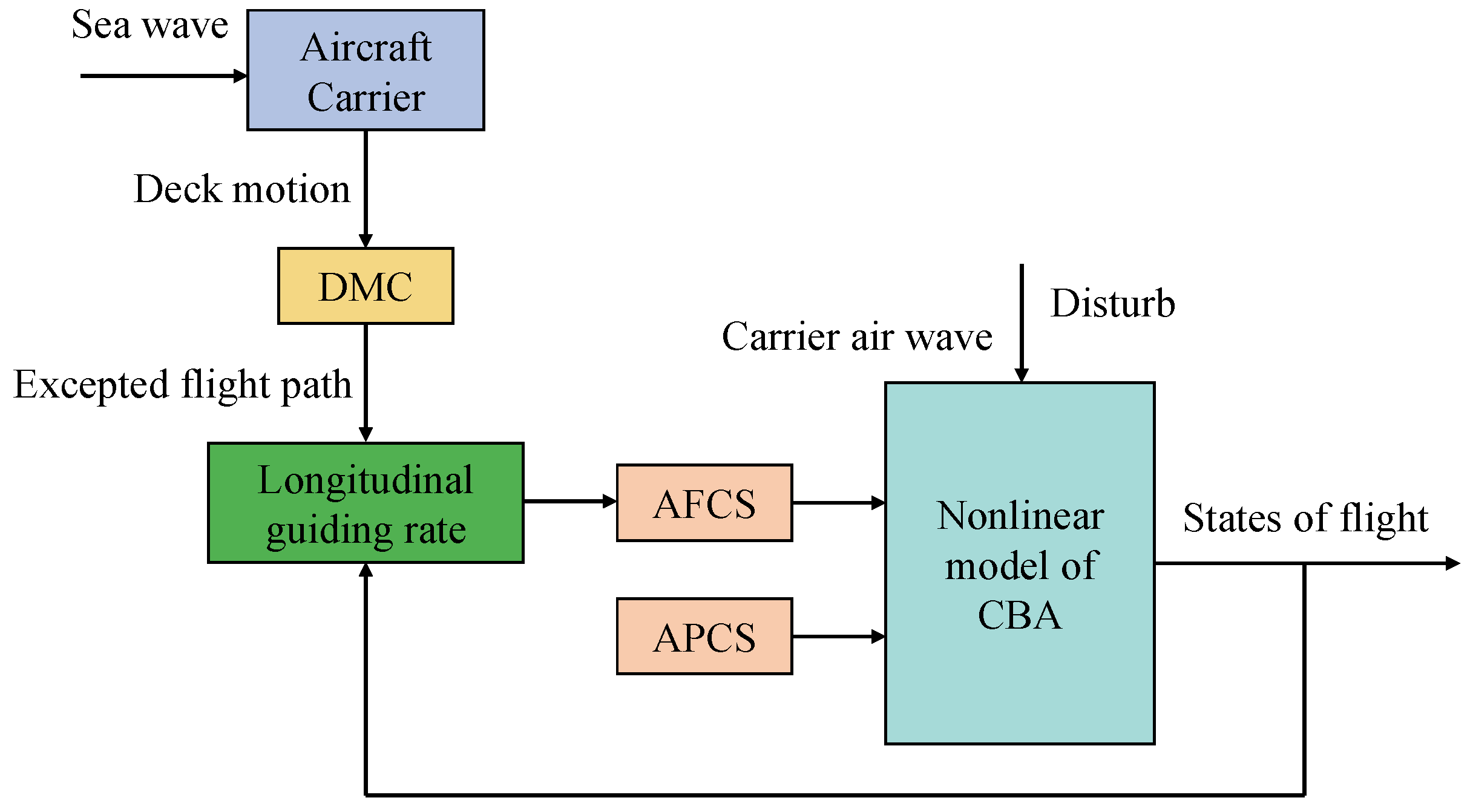
4. Design of the Longitudinal Automatic Landing System

The longitudinal landing system is designed to correct the deviation of the initial altitude, inhibit the carrier air wake disturbance and track and guide the glide path. When the CBA lands along the glide path, flight path control is realized through attitude control. Generally, the longitudinal landing system comprises the longitudinal guidance law that transforms the altitude error into the pitch angle instruction to control the variation in the pitch angle. The structural diagram of the longitudinal landing system is shown in Figure 7. The automatic flight control system (AFCS) corrects the CBA pitch angle and triggers variations in the track angle according to guidance instructions from the guidance system. The approach power compensation system (APCS) must be introduced in the landing stage to control and keep the angle of attack or velocity constant through the automatic accelerator to directly transform variations in the pitch angle into variations in the track angle. The AFCS, APCS and longitudinal guidance law are designed as follows.

4.1. Design of the AFCS

Considering the influence of disturbance on the CBA, the dynamic state of the pitch angle in Equation (1) can be changed as follows:
θ ¨ = f θ + g θ · δ e + d w
f θ = ρ V 2 S w c A 2 I y y C m 0 + C m α α + C m q q c A 2 V g θ = ρ V 2 S w c A C m δ e 2 I y y
where f θ and g θ represent nonlinear functions with an uncertainty of the elevator channel, δ e represents the input of the elevator channel and d w represents the sum of disturbances, including the CBA model uncertainty and carrier air-wake influences.
Therefore, the control input δ e can be written as Equation (34):
δ e = u θ z + u θ s
where:
u θ z = α ^ θ T ξ θ
u θ s = E ^ θ sgn s θ
The adaptive control laws are presented below:
α ^ ˙ θ = η θ 1 s θ ξ θ
E ^ ˙ θ = η θ 2 s θ

4.2. Design of the APCS

The APCS of the engine channel can automatically adjust the accelerator to maintain velocity stabilization during CBA landing, thereby decreasing the impact of the fluctuations in lifting force on the velocity. The attitude loop of the pitch angle is an internal loop for flight path tracking, with a rapid dynamic response and higher bandwidth than the velocity loop, so that the decoupling in the time scale can be realized through controlling the attitude and velocity by the dual channel.
The dynamic equation of airspeed in Equation (1) can be written as follows:
V = f V + g V · δ T + d T
where:
f V = ρ V 2 S w 2 m C D 0 + C D α 2 α 2 g sin γ g V = T m a x m cos α
where f V and g V represent nonlinear functions with accelerator channel uncertainty; δ T represents the input of the accelerator channel; and d T represents the unknown disturbance in the control system.
Therefore, the control input δ T can be written as Equation (41):
δ T = u V z + u V s
where:
u V z = α ^ V T ξ V
u V s = E ^ V sgn s V
The adaptive control laws are presented below:
α ^ ˙ V = η V 1 s V ξ V
E ^ ˙ V = η V 2 s V

4.3. Design of the Longitudinal Guidance Law

Considering the AFSMC angle of pitch-based control, the PID method is used to design the longitudinal guidance law expressed as Equation (47).
θ c = θ 0 + K p H + K i H 1 s + K d H s + K d d H s 2 H c H
where θ 0 represents the initial trim angle of thr pitch; H c represents the altitude instruction; and K p H , K i H , K d H and K d d H represent constant coefficients.

5. Simulations

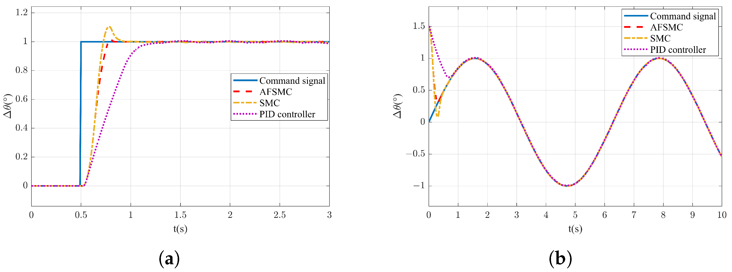
5.1. Parameter Settings and System Dynamic Response

The previously designed AFSMC is verified through simulation in this section, where the carrier air-wake disturbance is set and the USN CBA F/A-18A is selected as the sample aircraft for simulation. The aircraft carrier model is a Nimitz Aircraft CVN-68 with a water draft of 11.5 m, deck height of 30.6 m, and carrier deck above the sea level of 19.1 m. The F/A-18A has an altitude of 4.66 m, with the distance from the height of its center of gravity to the lowest point of the tail hook being 2 m. Without considering the influence of the pitch angle on this distance, the benchmark altitude of the ideal landing point H p is 21.1 m. For the CBA, the initial flight altitude H 0 is 114.3 m (375 ft), initial velocity V 0 is 70 m/s, benchmark angle of attack α 0 is 8.1° and glide path angle γ 0 is −3.5°.
In the adaptive fuzzy sliding-mode controller, the parameters are set as η θ 1 = 2 , η θ 2 = 0.4 , η V 1 = 1.8 , η V 2 = 0.5 , k θ 1 = 1.1 , k θ 2 = 1.0 , k V 1 = 1.2 and k V 2 = 1.0 . The adopted membership functions are:
μ N ( s ) = e s + π / 10 π / 20 2 μ Z ( s ) = e s π / 20 2 μ P ( s ) = e s π / 10 π / 20 2
In the longitudinal guidance law, the parameters are set as k p H = 1.5 , k i H = 0.2 , k d H = 0.01 and k d d H = 0.01 .
To verify the tracking performance of the pitch angle of the designed automatic landing system, the unit step signal and sinusoidal signal are introduced, and the simulation results are presented in Figure 8a,b. As observed in Figure 8a, the sliding-mode control method can reach the designated state faster than the traditional PID control method when a 0.5 s unit step signal is sent. Furthermore, AFSMC exhibits a smaller overshoot and requires a shorter adjustment time than the general SMC due to the introduction of adaptive control laws. Similarly, as observed in Figure 8b, AFSMC exhibits better rapidness and robustness in tracking the attitude angle of the CBA than PID control and general SMC control.

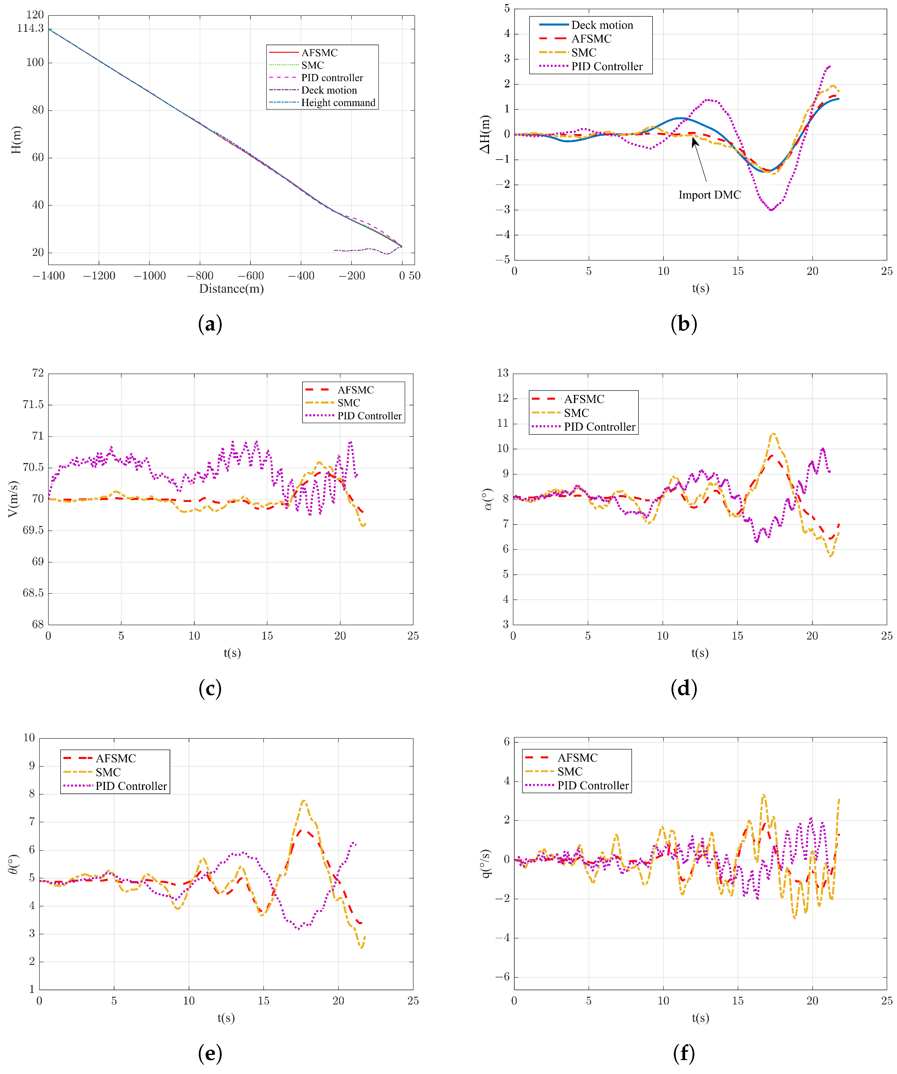
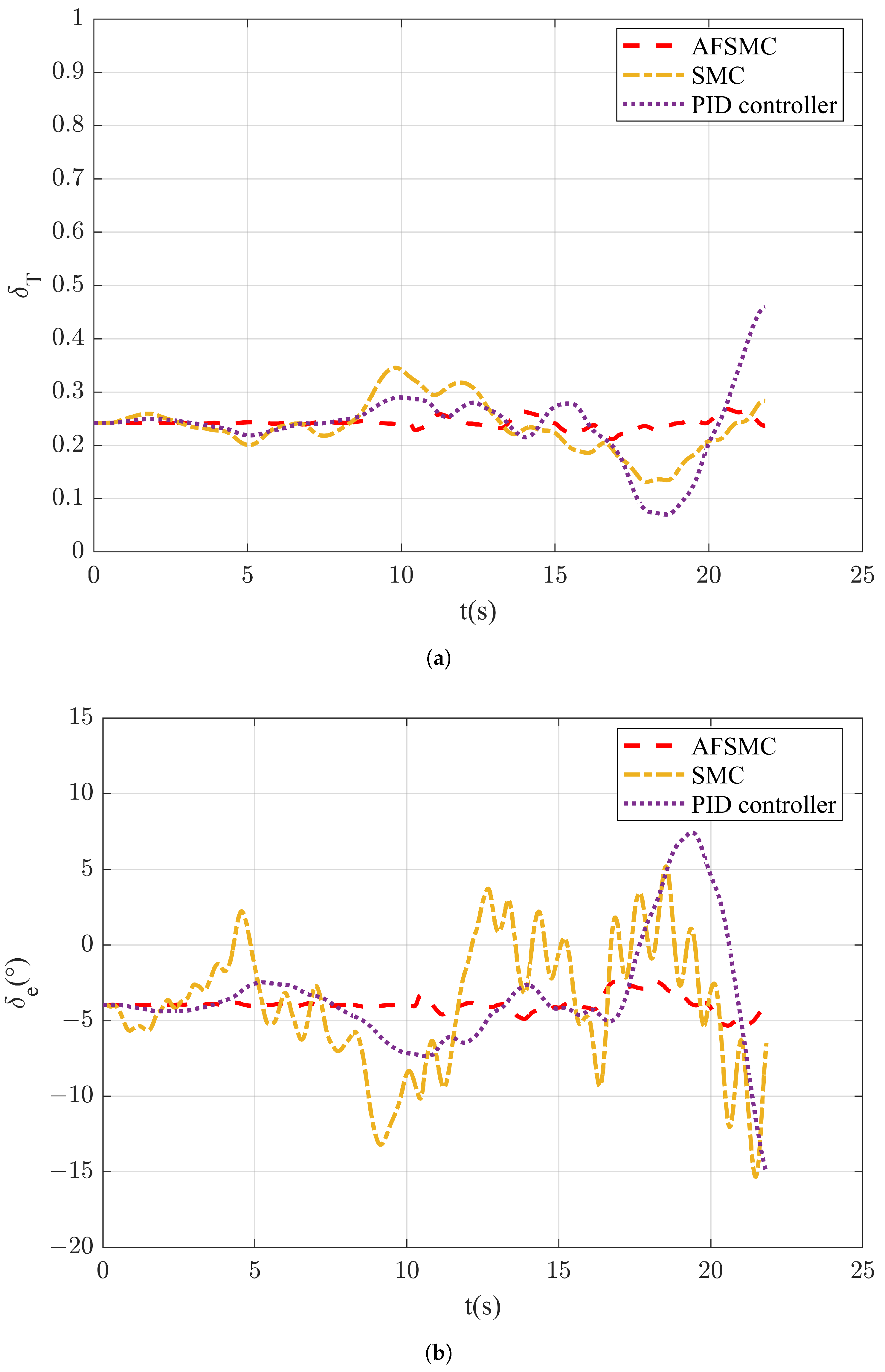
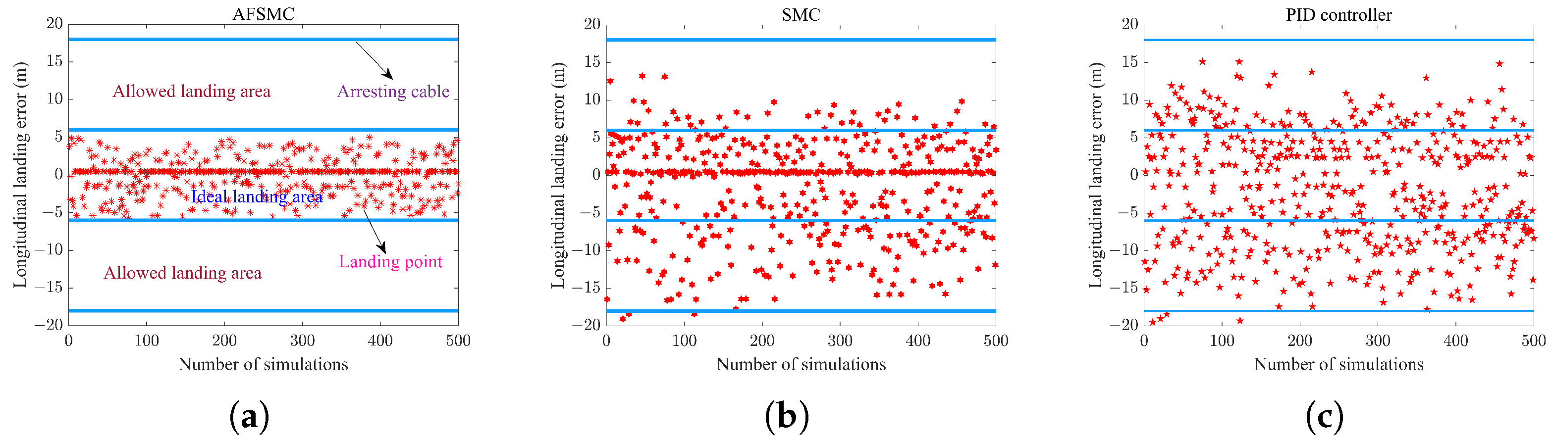
5.2. Carrier Landing Simulation and Monte Carlo Target Shooting Testing

The simulation results of the CBA in the entire landing process are shown in Figure 9 and Figure 10.
As seen in Figure 9a,b, the designed longitudinal automatic landing system based on the adaptive fuzzy sliding mode can reach a satisfactory landing effect. Under the same adjustment time, the proposed AFSMC exhibits a smaller overshoot in the process of adjusting altitude than the traditional PID and SMC controllers. When the motion of the carrier deck and carrier air-wake disturbance are introduced, the CBA exhibits a sudden change in its state, and the designed AFSMC exhibits smaller errors while the control methods show fluctuations even though their altitude errors satisfy the landing requirements.
Figure 9c,d depict the response curves of the angle of attack and velocity, respectively. The AFSMC exhibits a stronger capacity for maintaining the attack angle and velocity and compensates for stronger rapidness and stability for carrier air-wake disturbances than the traditional PID and SMC controllers.
Figure 9e,f depict the variation curve of the pitch angle and the curve of the rate of pitch variation. The AFSMC exhibits better convergence capacity in the flight attitude of the CBA than the traditional PID and SMC controllers.
Figure 10 depicts the curve of deviations of the elevator and accelerator rudders during CBA landing. The introduction of the switching controller considerably prevents buffeting of the actuator during actual landing and exhibits excellent control performance.
To more intuitively demonstrate the control effect of the designed AFSMC, 500 groups of experiments were performed for the adaptive sliding-mode control and traditional control algorithms under the medium sea state. In this Monte Carlo target-testing simulation experiment, we generated white noise using 500 random number seeds to simulate the carrier air wake as described in Equation (2) and the carrier-base aircraft deck motions as outlined in Equations (3) and (4). We conducted Monte Carlo simulations to assess the initial height deviations of the carrier-based aircraft as it enters the ideal glide path. In each simulation, the initial height was randomly sampled within the range of H 0 ± 3 m , the initial speed remained at 70 m/s, and the initial conditions for other state variables were consistent with those set in Section 5.1. Figure 11 presents the statistical results of the landing points in different schemes based on the Monte Carlo random target shooting and simulation experiment. As seen in Figure 11a, the AFSMC exhibits a more concentrated distribution of the landing points and a higher success rate of arresting. Therefore, the designed AFSMC exhibits a more stable control effect, better landing accuracy, better quality and a stronger capacity for preventing random disturbance.

6. Conclusions

For the complex conditions of landing, a new automatic landing control method based on the combination of integral sliding-mode control and an adaptive fuzzy system is proposed. In addition, an adaptive fuzzy network is introduced to implement fuzzy approximation for the control input of the actuator. Furthermore, adaptive laws are designed for the switching controller without estimating the upper limit of the uncertain system, which could prevent buffeting well by maintaining the rapidity and robustness of the sliding-mode control. Moreover, the sliding-mode switching function is considered an input of the fuzzy controller; thus, the number of fuzzy rules is considerably reduced to present a simple design of the whole control system for engineering applications. The numerical simulation verifies the good control accuracy and robustness of the control method. The automatic landing system for the CBA is built to complete the design and simulation of each module. The comprehensive simulation results reveal that the CBA landing results satisfy the performance requirements for the landing of the USN under the effect of AFSMC. Moreover, the landing accuracy and performance are considerably improved compared to the general SMC control and traditional PID control technology.

Author Contributions

Methodology, H.Z., R.M. and Z.X.; resources, H.Z., R.M. and Z.X.; writing—original draft preparation, H.Z. and Z.X.; writing—review and editing, R.M. and J.A.; visualization, H.Z. and Z.X.; supervision, Z.X. and J.A.; project administration, J.A. All authors have read and agreed to the published version of the manuscript.

Funding

This research received no external funding.

Data Availability Statement

The data presented in this study are available on request from the corresponding author. The data are not publicly available due to the involvement of sensitive information about carrier-based aircraft in this research data.

Conflicts of Interest

The authors declare no conflicts of interest.

References

  1. Liu, D.; Wu, J.; Zhou, Y.; Liu, Z.; Li, Y.; Wang, M. Practice and prospects of comprehensive support technologies of carrier-based aircraft. Hang Kong Xue Bao 2021, 42, 1. [Google Scholar]
  2. Johnson, G.; Peterson, B.; Taylor, J.; McCarthy, C. Test results of F/A-18 autoland trials for aircraft carrier operations. In Proceedings of the 2001 IEEE Aerospace Conference Proceedings (Cat. No. 01TH8542), Big Sky, MT, USA, 10–17 March 2001; Volume 3, pp. 3–1283. [Google Scholar]
  3. Zhang, W.; Zhang, Z.; Zhu, Q.; Xu, S. Dynamics model of carrier-based aircraft landing gears landed on dynamic deck. Chin. J. Aeronaut. 2009, 22, 371–379. [Google Scholar]
  4. Zhou, J.; Zeng, J.; Chen, J.; Tong, M. Analysis of Global Sensitivity of Landing Variables on Landing Loads and Extreme Values of the Loads in Carrier-Based Aircrafts. Int. J. Aerosp. Eng. 2018, 2018, 2105682. [Google Scholar] [CrossRef]
  5. Yang, X.; Yang, J.; Zhang, Z.; Ma, J.; Sun, Y.; Liu, H. A review of civil aircraft arresting system for runway overruns. Prog. Aerosp. Sci. 2018, 102, 99–121. [Google Scholar] [CrossRef]
  6. Yue, L.; Liu, G.; Hong, G. Design and simulation of F/A-18A automatic carrier landing guidance controller. In Proceedings of the AIAA Modeling and Simulation Technologies Conference, Washington, DC, USA, 13–17 June 2016; p. 3527. [Google Scholar]
  7. Urnes, J.; Hess, R. Development of the F/A-18A automatic carrier landing system. J. Guid. Control Dyn. 1985, 8, 289–295. [Google Scholar] [CrossRef]
  8. Sweger, J.F. Design Specifications Development for Unmanned Aircraft Carrier Landings: A Simulation Approach; US Naval Academy: Naval Academy, MD, USA, 2003. [Google Scholar]
  9. Mariano, I. Autonomous Landing System for a UAV. Master’s Thesis, Monterey California, Naval Post Graduate School, Monterey, CA, USA, 2004. [Google Scholar]
  10. JM Urnes, R.H.; Moomaw, R.; Huff, R. H-dot automatic carrier landing system for approach control in turbulence. J. Guid. Control 1981, 4, 177–183. [Google Scholar] [CrossRef]
  11. Misra, G.; Bai, X. Output-feedback stochastic model predictive control for glideslope tracking during aircraft carrier landing. J. Guid. Control Dyn. 2019, 42, 2098–2105. [Google Scholar] [CrossRef]
  12. Deng, J.; Yan, Z.; Ai, J. Application of fuzzy control technology to automatic carrier landing system. J. Syst. Simul. 2012, 24, 645–650. [Google Scholar]
  13. Yu, Y.; Wang, H.; Li, N.; Su, Z.; Wu, J. Automatic carrier landing system based on active disturbance rejection control with a novel parameters optimizer. Aerosp. Sci. Technol. 2017, 69, 149–160. [Google Scholar] [CrossRef]
  14. Wu, Z.; Ni, J.; Qian, W.; Bu, X.; Liu, B. Composite prescribed performance control of small unmanned aerial vehicles using modified nonlinear disturbance observer. ISA Trans. 2021, 116, 30–45. [Google Scholar] [CrossRef]
  15. Zhen, Z.; Jiang, S.; Ma, K. Automatic carrier landing control for unmanned aerial vehicles based on preview control and particle filtering. Aerosp. Sci. Technol. 2018, 81, 99–107. [Google Scholar] [CrossRef]
  16. Geng, J.; Yao, H.; Zhang, H. Studies on effect of air wake on slope and landing property of carrier aircraft. J. Syst. Simul. 2009, 21, 5940–5943. [Google Scholar]
  17. Luo, F.; Zhang, J.; Lyu, P.; Liu, Z.; Tang, W. Carrier-based aircraft precision landing using direct lift control based on incremental nonlinear dynamic inversion. IEEE Access 2022, 10, 55709–55725. [Google Scholar] [CrossRef]
  18. Guan, Z.; Ma, Y.; Zheng, Z.; Guo, N. Prescribed performance control for automatic carrier landing with disturbance. Nonlinear Dyn. 2018, 94, 1335–1349. [Google Scholar] [CrossRef]
  19. Subrahmanyam, M.B. H-infinity design of F/A-18A automatic carrier landing system. J. Guid. Control Dyn. 1994, 17, 187–191. [Google Scholar] [CrossRef]
  20. Zhang, Y.; Liu, J.; He, W. Adaptive fault-tolerant control for a nonlinear flexible aircraft wing system. Asian J. Control 2019, 21, 2340–2351. [Google Scholar] [CrossRef]
  21. Lungu, M.; Chen, M.; Vîlcică, D.A. Backstepping-and sliding mode-based automatic carrier landing system with deck motion estimation and compensation. Aerospace 2022, 9, 644. [Google Scholar] [CrossRef]
  22. Moulay, E.; Léchappé, V.; Bernuau, E.; Defoort, M.; Plestan, F. Fixed-time sliding-mode control with mismatched disturbances. Automatica 2022, 136, 110009. [Google Scholar] [CrossRef]
  23. Xiao, H.; Zhen, Z.; Xue, Y. Fault-tolerant attitude tracking control for carrier-based aircraft using RBFNN-based adaptive second-order sliding-mode control. Aerosp. Sci. Technol. 2023, 139, 108408. [Google Scholar] [CrossRef]
  24. Mofid, O.; Mobayen, S. Adaptive finite-time backstepping global sliding mode tracker of quad-rotor UAVs under model uncertainty, wind perturbation, and input saturation. IEEE Trans. Aerosp. Electron. Syst. 2021, 58, 140–151. [Google Scholar] [CrossRef]
  25. Dilmi, S. Enhancing flight envelope for a nonlinear aeroelastic wing-section using adaptive fuzzy sliding-mode control law. J. Aerosp. Eng. 2022, 35, 04022009. [Google Scholar] [CrossRef]
  26. Tian, Y.; Hu, Q.; Shao, X. Adaptive fault-tolerant control for attitude reorientation under complex attitude constraints. Aerosp. Sci. Technol. 2022, 121, 107332. [Google Scholar] [CrossRef]
  27. Xue, Y.; Zhen, Z.; Zhang, Z.; Cao, T.; Wan, T. Automatic carrier landing for UAV based on integrated disturbance observer and fault-tolerant control. Aircr. Eng. Aerosp. Technol. 2023, 95, 1247–1256. [Google Scholar] [CrossRef]
  28. Zhu, Q.; Yang, Z. Dynamic recurrent fuzzy neural network-based adaptive sliding control for longitudinal automatic carrier landing system. J. Intell. Fuzzy Syst. 2019, 37, 53–62. [Google Scholar] [CrossRef]
  29. Yao, Z.; Kan, Z.; Zhen, C.; Shao, H.; Li, D. Fault-Tolerant control for carrier-based UAV based on sliding mode method. Drones 2023, 7, 194. [Google Scholar] [CrossRef]
  30. Xu, D.; Liu, X.; Wang, L. Influence of carrier motion on landing safety for carrier-based airplanes. J. Beijing Univ. Aeronaut. Astronaut. 2011, 37, 289–294. [Google Scholar]
  31. Moorhouse, D.J.; Woodcock, R.J. Background Information and User Guide for MIL-F-8785C, Military Specification-Flying Qualities of Piloted Airplanes; Flight Dynamics Laboratory: Wright-Patterson AFB, OH, USA, 1982. [Google Scholar]
  32. Beal, T. Digital simulation of atmospheric turbulence for Dryden and von Karman models. J. Guid. Control Dyn. 1993, 16, 132–138. [Google Scholar] [CrossRef]
  33. Higgins, C.W.; Froidevaux, M.; Simeonov, V.; Vercauteren, N.; Barry, C.; Parlange, M.B. The effect of scale on the applicability of Taylor’s frozen turbulence hypothesis in the atmospheric boundary layer. Bound.-Layer Meteorol. 2012, 143, 379–391. [Google Scholar] [CrossRef]
  34. Deng, J. Research on the Theory and Simulation of Longitudinal Control System Design for Carrier-Based Aircraft Automatic Landing. Ph.D. Thesis, Fudan University, Shanghai, China, 2010. [Google Scholar]
  35. Li, A.; Liu, M.; Cao, X.; Liu, R. Adaptive quantized sliding mode attitude tracking control for flexible spacecraft with input dead-zone via Takagi-Sugeno fuzzy approach. Inf. Sci. 2022, 587, 746–773. [Google Scholar] [CrossRef]
  36. Van, M.; Ge, S.S. Adaptive fuzzy integral sliding-mode control for robust fault-tolerant control of robot manipulators with disturbance observer. IEEE Trans. Fuzzy Syst. 2020, 29, 1284–1296. [Google Scholar] [CrossRef]
Figure 1. Horizontal components of the carrier air wake.
Actuators 14 00114 g001
Figure 2. Longitudinal components of the carrier air wake.
Actuators 14 00114 g002
Figure 3. Curve of the pitching motion.
Actuators 14 00114 g003
Figure 4. Curve of the heaving motion.
Actuators 14 00114 g004
Figure 5. Altitude variation of the ideal landing points.
Actuators 14 00114 g005
Figure 6. Structural diagram of the AFSMC.
Actuators 14 00114 g006
Figure 7. Structural diagram of the longitudinal landing system.
Actuators 14 00114 g007
Figure 8. Response curve of the pitch angle under different types of signals. (a) Response curve of the pitch angle under the step signal; (b) response curve of the pitch angle under the sinusoidal signal.
Actuators 14 00114 g008
Figure 9. Response curve of the flight states. (a) Response curve of altitude; (b) response curve of altitude error; (c) response curve of the angle of attack; (d) response curve of velocity; (e) response curve of the pitch angle; (f) response curve of the rate of pitch.
Actuators 14 00114 g009
Figure 10. Curve graph of deviation for each control surface. (a) Response curve of the accelerator; (b) response curve of the elevator.
Actuators 14 00114 g010
Figure 11. Distribution diagram of the landing points on carrier-based aircraft. (a) Simulation result of AFSMC; (b) simulation result of SMC; (c) simulation result of the PID controller.
Actuators 14 00114 g011
Disclaimer/Publisher’s Note: The statements, opinions and data contained in all publications are solely those of the individual author(s) and contributor(s) and not of MDPI and/or the editor(s). MDPI and/or the editor(s) disclaim responsibility for any injury to people or property resulting from any ideas, methods, instructions or products referred to in the content.

