Article

Integrating Strain Gauge Feedback with Adaptive Sliding Mode Motion Control for Piezoelectric Nanopositioning Stage

1
School of Mechanical and Electrical Engineering, Wuhan Institute of Technology, Wuhan 430205, China
2
Zhuhai Huaya Machinery Technology Co., Ltd., Zhuhai 519000, China
3
Hubei Provincial Engineering Technology Research Center of Green Chemical Equipment, School of Mechanical and Electrical Engineering, Wuhan Institute of Technology, Wuhan 430205, China
4
Hubei Provincial Key Laboratory of Chemical Equipment Intensification and Intrinsic Safety, School of Mechanical and Electrical Engineering, Wuhan Institute of Technology, Wuhan 430205, China
5
School of Mechanical and Electrical Engineering, Guilin University of Electronic Technology, Guilin 541000, China
*
Author to whom correspondence should be addressed.
Actuators 2025, 14(2), 79; https://doi.org/10.3390/act14020079
Submission received: 31 December 2024 / Revised: 27 January 2025 / Accepted: 3 February 2025 / Published: 7 February 2025
(This article belongs to the Section Precision Actuators)

Abstract

:
This paper presents an adaptive sliding mode control (ASMC) scheme based on strain gauge position feedback for compensating for motion errors in a piezoelectric nanopositioning stages and ensures precise and reliable motion tracking control. The innovation of this scheme lies in calibrating the relationship between the feedback voltage of the strain gauge and the actual stage displacement. Thus, the calibrated feedback displacement is directly used as the position feedback signal for the ASMC scheme. Adaptive rules are employed to adjust the control gains, thereby eliminating the requirement to determine the upper bound of the disturbance. The stability of the ASMC strategy is theoretically proven within the Lyapunov framework. Comparative experiments under external disturbances have confirmed the superiority of the proposed control scheme. Results demonstrate that the proposed control scheme exhibits superior robust tracking performance compared to the traditional sliding mode control (SMC) scheme.

1. Introduction

Piezoelectric nanopositioning stages driven by a piezoelectric actuator is widely used in engineering with nanometer-level precision, such as the atomic force microscope [1,2], precision machining [3,4], and optical focusing [5]. Piezoelectric actuators are commonly employed as driving elements due to their compelling advantages including compact size, substantial output force, swift response, and high resolution among other merits. However, the intrinsic hysteresis nonlinearity of piezoelectric actuator poses a significant challenge to enhance the positioning accuracy of piezoelectric nanopositioning stages. The effective method to compensate for hysteresis nonlinearity is to use closed-loop control scheme. In the literature, a variety of closed-loop control schemes have been formulated to fulfill the precision positioning demands of piezoelectric nanopositioning stages [6,7,8,9,10].
Feedback is the cornerstone of closed-loop control system, enabling the compensation for hysteresis nonlinearity and ensuring precise positioning. As referenced in [11], strain gauges integrated into piezoelectric actuators provide precise displacement feedback. The combination of the feedback with the PID closed-loop controller mitigates the inherent hysteresis of the nanopositioning stage. Furthermore, as referenced in [12], the capacitive displacement sensor’s feedback combined with the PID closed-loop control scheme compensates for the nanopositioning stage’s hysteresis nonlinearity. Recognizing the limitations of traditional control methods in addressing hysteresis nonlinearity, it is crucial to develop superior control schemes which integrate feedback mechanisms to enhance positioning accuracy. Therefore, this paper concentrates on the robust control design for a nanopositioning system, utilizing feedback mechanisms.
Sliding mode control (SMC) is a robust nonlinear control scheme. Due to its robustness against changes in parameters and external disturbances, the scheme has been extensively applied across various domains [13,14,15,16,17]. The essence of SMC lies in the design of appropriate sliding surfaces and control laws that compel the system state trajectory to swiftly converge to the sliding surface. Once on this surface, the control system glides smoothly towards the target. Furthermore, ensuring the robustness and stability of the control system under uncertainties and external disturbances is vital. This requires the precise estimation of the boundary values for uncertainties and disturbances during the parameters design for SMC controller. However, in practice, an overly large boundary value leads to severe chattering, while a small one may fail to accommodate the system’s uncertainties and disturbances. Therefore, adopting appropriate methods for boundary value estimation is essential. The adaptive control method estimates the uncertain parameters of the system through online adaptive processes and dynamically adjusts the control law to cope with these uncertainties. Thereby, it achieves the estimation and control of the boundary values of sliding mode control. The performance of the adaptive SMC (ASMC) scheme, which combines adaptive control and sliding mode control, is verified in numerous works in the literature [18,19,20,21,22]. It is demonstrated that the ASMC scheme applied to the piezoelectric nanopositioning stage can achieve nanometer-level precision [23,24,25,26,27].
Real-time feedback is an essential component of SMC in closed-loop systems. The literature indicates that resistance strain gauges [28], capacitive sensors [29,30], piezoelectric sensors [31], and laser interferometer [32] are the key components used for displacement feedback in positioning stages [33]. In particular, resistance strain gauges are highly suitable to be integrated into space-limited stages due to their compactness, high accuracy, simple structure, low cost, and lightweight design. The strain gauges detect minor deformations in the stage’s motion structure by monitoring slight changes in electrical resistance. Therefore, resistance strain gauges are employed on piezoelectric nanopositioning stages to quantify the elastic deformation within a one-dimensional bistable beam [34,35]. Capitalizing on the beam buckling phenomenon, these compliant mechanisms ensure smooth output displacement via controlled elastic deformation [36]. Consequently, by employing resistance strain gauges to measure the elastic deformation of bistable beam, the displacement of the piezoelectric nanopositioning stages can be directly measured, providing real-time feedback for SMC.
To this end, a novel method is proposed, which designs an ASMC scheme for piezoelectric nanopositioning stages based on strain gauge displacement feedback. The scheme offers the benefits of precision, robustness, adaptability, and simplicity in implementation. For comparison, the SMC strategy is developed to highlight the advantages of the proposed ASMC scheme. The scheme is economically viable and facilitates the integration of multiple devices. This makes it attractive for practical applications. The stability of the control system is proved in theory, and the effectiveness of the proposed control scheme is validated through experimental studies on the piezoelectric nanopositioning stages.
This paper is structured in the following parts. Section 2 delineates the fundamental principles of strain gauge displacement measurement. Section 3 presents the dynamic modeling. Section 4 provides a detailed explanation of the design of the SMC scheme and its stability analysis. Section 5 describes the experimental setup and conducts system identification. Section 6 details a series of experimental studies. Finally, Section 7 summarizes the main conclusions of the paper.

2. Structural Analysis

The 3D model of the piezoelectric nanopositioning stage is shown in Figure 1. The stage is designed to operate in low-frequency and light-load conditions. The stage is symmetrically designed. It is fixed by four bolts. A piezoelectric actuator is centrally mounted in a rectangular zone to offer nanometer level steps. The piezoelectric actuator is installed using an interference fit and directly clamped by the surrounding structure. This design ensures no gaps between contact surfaces. The guiding flexure hinges are employed to ensure the linearity of the stage. Regarding the flexure hinges of the stage, the translational stiffness K can be regarded as
K = E b t 3 4 l 3
where E represents the Young’s modulus, b denotes the width of the beam, t signifies the thickness of the beam, and l corresponds to the length of the beam.
Due to the symmetry location of stage along X axis, an analysis is conducted on the half part in Figure 1. Beam A1 and Beam A2 span the length of l 1 , and Beam B1 and Beam B2 are characterized by a length of l 2 . Meanwhile, Beam C extends over a length of l 3 . Beam B2 is connected in series with Beam C, and this combination is then paralleled with Beam A1. Additionally, Beam A2 is paralleled with Beam B1. Finally, the assembly of Beam A1 with -B2 and -C is connected in series with the parallel combination of Beam A2 and -B1. Hence, based on Equation (1), the stiffness K 1 of A1 and A2 is given by
K 1 = E b t 3 4 l 1 3
The stiffness K 2 of B1 and B2 is determined as follows:
K 2 = E b t 3 4 l 2 3
The stiffness K 3 of the Beam C can be expressed as
K 3 = E b t 3 4 l 3 3
Following the beam relationships previously discussed, the calculations reveal that the stiffness K r on the right side of the stage is given by
K r = E b t 3 ( l 1 3 + l 2 3 ) 4 l 1 3
Ultimately, leveraging the structural symmetry, the ideal stiffness K d of the stage can be derived as follows:
K d = 2 K r = E b t 3 ( l 1 3 + l 2 3 ) 2 l 1 3
Thus, the relationship between the stage’s displacement x and the force F exerted by the piezoelectric actuator on the stage can be formulated as follows:
F = K d x
The direct proportionality between the input voltage and the output force of the piezoelectric actuator is considered. Together with Equation (7), it allows for the conclusion that the input voltage is proportional to the displacement of the stage. Based on this principle, the ideal displacement value of the stage can be calculated from the input voltage. Furthermore, by integrating the analysis from Equations (6) and (7), the ideal stiffness K d of the stage is a critical factor affecting the stage’s displacement. Adjusting K d can either increase or decrease the maximum and minimum displacements of the stage. And, it also impacts the resolution of the stage’s motion.

3. Dynamics Modeling

In general, the system’s dynamics can be described by the following model:
m x ¨ t + b x ˙ t + k x t = d u t + H t .
where t signifies the time variable, u represents the input driving voltage, and x is the output displacement. The parameters m , b , k , and d correspond to the system’s intrinsic characteristics, which are the mass, damping coefficient, stiffness, and nominal voltage-to-force coefficient, respectively. The term H ( t ) indicates the combined effects of external disturbances and hysteresis within the system.
Assumption 1. 
The lumped disturbance H ( t ) is bounded as
H ( t ) H .
where the constant H > 0 .
Based on the aforementioned model, the control objective is to formulate a strategy that ensures the system tracks the desired motion trajectory x d t despite the presence of lumped disturbances H ( t ) . To accomplish this precise motion control, an adaptive sliding mode control scheme has been devised as detailed in Section 4.

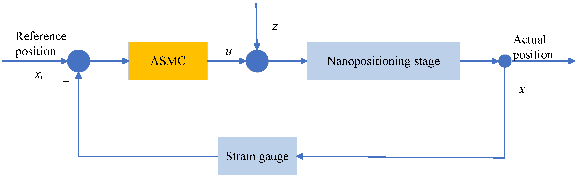
4. Sliding Mode Controller Design

This section introduces the design of the adaptive sliding mode control scheme, which is specifically tailored to minimize the tracking error. The aim of this scheme is to ensure that the system output adheres closely to the desired trajectory, even in the face of uncertainties and disturbances. The forthcoming discussion will detail the controller’s design.
The tracking error is defined as
e t = x t x d t ,
where x d t is the desired position trajectory, and x ( t ) is the actual position trajectory.
In this research, a proportional–derivative type of sliding surface is selected based on the tracking error e, which is defined as follows:
s t = c e t + e ˙ t .
Here, the parameter c > 0 is a positive constant, ensuring that the system satisfies the Hurwitz stability criterion. Consequently, the dynamics model described by the preceding equation can be reformulated as
e ˙ = e 1 e ˙ 1 = 1 m d u t + H t k x t b x ˙ t x ¨ d .
Theorem 1. 
In the context of system Equation (8), which incorporates a sliding function, the tracking error Equation (10) is designed to converge to zero within a finite time frame. This convergence is facilitated by the following reaching law, which plays a crucial role in the system’s behavior. The reaching law ensures that the system state reaches and maintains its desired trajectory with swift precision.
s ˙ = ε s g n s p s ,
where ε > 0 and p > 0 .
To estimate the disturbance term H ( t ) , an adaptive law is introduced. The purpose of the adaptive law is to adjust the estimated disturbance H ^ ( t ) so that it can track H ( t ) . For the system in question, the following form of the adaptive law is selected:
H ^ ˙ = λ s ,
where λ is a positive constant that governs the convergence rate of the adaptive law.
In the process of formulating Equations (12) and (13), the controller can be deduced accordingly as
u ( t ) = 1 d m x ¨ ( t ) + b x ˙ ( t ) + k x ( t ) H ^ ( t ) ε d s g n ( s ( t ) ) p d s ( t )
Proof. 
To establish the system’s stability, the Lyapunov method is utilized. A Lyapunov function V ( t ) is defined as follows:
V ( t ) = 1 2 s 2 ( t ) + 1 2 λ ( H ^ ( t ) H ( t ) ) 2 ,
and next, compute the derivative V ˙ ( t ) of the function V ( t ) ,
V ˙ ( t ) = s ( t ) s ˙ ( t ) + 1 λ ( H ^ ( t ) H ( t ) ) H ^ ˙ ( t ) .
Upon integrating the sliding mode control law and adaptive law into Equation (17), the subsequent result is obtained.
V ˙ ( t ) = s ( t ) ε s g n ( s ( t ) ) p s ( t ) + 1 λ ( H ^ ( t ) H ( t ) ) λ s ( t ) .
Simplifying the expression yields:
V ˙ ( t ) = ε | s ( t ) | p s 2 ( t ) + s ( t ) H ^ ( t ) s ( t ) H ( t ) .
When s ( t ) 0 , since ε > 0 and p > 0 , and the terms s ( t ) H ^ ( t ) and s ( t ) H ( t ) are negligible compared to the terms | s ( t ) | and s 2 ( t ) as s ( t ) approaches zero, it follows that V ˙ ( t ) is negative definite, indicating that V ( t ) is non-increasing. When s ( t ) = 0 , V ˙ ( t ) = 0 , indicating that V ( t ) is constant. Therefore, according to the Lyapunov stability theory, the system is stable. □
Remark 1. 
From Equation (12), it is evident that the second-order derivative x ¨ d ( t ) of the desired position is employed by the controller. In this control system, the desired position is pre-defined, and hence it is assumed that x ¨ d ( t ) is accessible.
Remark 2. 
In the context of the reaching law Equation (13), to achieve rapid convergence and reduce the chattering effect, it is necessary to increase the parameter p while diminishing the value of ε. However, the practical implementation of a high p-value, coupled with the discontinuity inherent in the sign function, can lead to pronounced chattering. Consequently, to alleviate this chattering, a saturation function is employed in place of the sign function:
s a t ( s ) = s g n ( s ) , i f | s | > Δ k s , i f | s | Δ
where Δ is the boundary layer, k = 1 / Δ .

5. Experimental Setup

5.1. Experimental Equipment

The experimental setup is illustrated in Figure 2. The stage is driven by a PZT actuator (model: PSt150/3.5*3.5/7L, from core morrow). The motion control card (model: GCN400V-S, from Gaochauto, Shenzhen, China) possesses analog control capabilities and serves as an output for analog signals. The data acquisition card (model: DAQ122, from Lingzhi Electronics, Fuzhou, China) facilitates high-speed and high-frequency real-time data transmission for the acquisition of analog data. The strain gauge sensor (model: TP-5-120, from Bengbu Kechuang, Bengbu, China), known for its low cost, high sensitivity, and minimal hysteresis, functions as a displacement sensor. The signal amplifier (model: UP3201, from UP, Beijing, China) amplifies the tiny analog signals before being sent to the data acquisition card. The laser interferometer (model: XL-80, from Renishaw, Gloucestershire, London, UK) is utilized for the precise measurement of actual displacement. The self-developed voltage amplification board (model: CH341PAR, from ZhuHai HuaYa, Zhuhai, China) boasts a voltage amplification ratio of 27.54, effectively amplifying a 3.6 V voltage to 99 V. The experiments are conducted on a vibration isolation table (model: ZDT-B-MOT, from Liansheng, Nanchang, China). The experiment generates ideal position signals utilizing LabVIEW 2021 and employs this software to implement the control laws. The resistance strain gauge sensor captures voltage data and relays them back to the data acquisition card, which in turn transmits the signal to LabVIEW for further processing.

5.2. System Identification

By employing the Particle Swarm Optimization (PSO) algorithm to estimate the unknown model parameters within Equation (8), the results are systematically compiled in Table 1.

5.3. Controller Setup

To validate the efficacy of the proposed control scheme, comparative experiments are conducted between SMC and ASMC for the piezoelectric nanopositioning stage. The control scheme’s architecture is depicted in Figure 3.
The parameters of the control scheme are shown in Table 2. The determination of ASMC and SMC parameters is achieved through a synergistic approach of numerical simulation and experimental fine-tuning. The limitations of the equipment and the need to balance control performance and computational efficiency are carefully considered. The ASMC only adds a simple parameter adaptation mechanism to more effectively handle disturbances. Compared with SMC, there is no significant increase in computational load.
The experimental setup utilizes an ideal signal, which is presented as follows:
x d t = A s i n 2 π f t π 2 + A ,
In this experiment, the time variable t is measured in milliseconds (ms), the amplitude A is quantified in volts (V), and the frequency f is given in hertz (Hz). Specifically, the amplitude A is set to 1 V. The frequency f is alternated between 0.005 Hz and 0.01 Hz. This limitation is primarily due to the performance constraints of our current equipment. Specifically, the system response time is relatively long.
To objectively assess and compare the tracking performance, the root mean square e r m s and the maximum absolute error e m a x indices are established as follows:
e r m s = i = 1 N x i x d i 2 N , e m a x = m a x x i x d i .

6. Results and Discussion

6.1. Parameter Calibration Results

The input signal and strain gauge feedback are both in the form of voltage, while the experiment’s actual measurement is focused on displacement. To intuitively correlate the experimental outcomes of the sine tracking experiment, a two-step calibration process is essential. The first step is to calculate the reference displacement, and feedback displacement derived from the input voltage and the feedback voltage. The second step is to compare these values with the displacement measurements obtained from the interferometer. To accurately determine the reference displacement, a calibration of the relationship between the input voltage and the actual displacement is conducted. Similarly, to determine the feedback displacement, a separate calibration of the relationship between the strain gauge feedback voltage and the actual displacement is also performed. To ensure sustained high performance, regular recalibration of the strain gauges and environmental compensation are essential. In this experiment, the actual displacement values for five sinusoidal waves and their corresponding input and strain gauge feedback voltages were carefully collected. The input voltage ratio over actual displacement was found by using the average amplitude of the five sinusoidal waves and the amplitude of the input voltage. The calculation involves dividing the average amplitude by the amplitude of the input voltage. In this experiment, the ratio of input voltage over actual displacement is found to be 2.1 μ m/V as derived from the collected data. The relationship between the feedback voltage of the strain gauge and the fitted actual displacement is shown in Figure 4. The ratio of the feedback voltage over actual displacement is determined to be 4.22 μ m/V.

6.2. Resolution Test for Nanopositioning Movement

Figure 5 presents the results of the resolution test. In this figure, the solid, dashed, and dotted lines represent the reference positions, actual positions, and feedback positions, respectively. The stage’s resolution is determined to be around 18 nanometers. Minor discrepancies in the feedback position can be ascribed to sensor limitations and system response times, especially during step transitions.

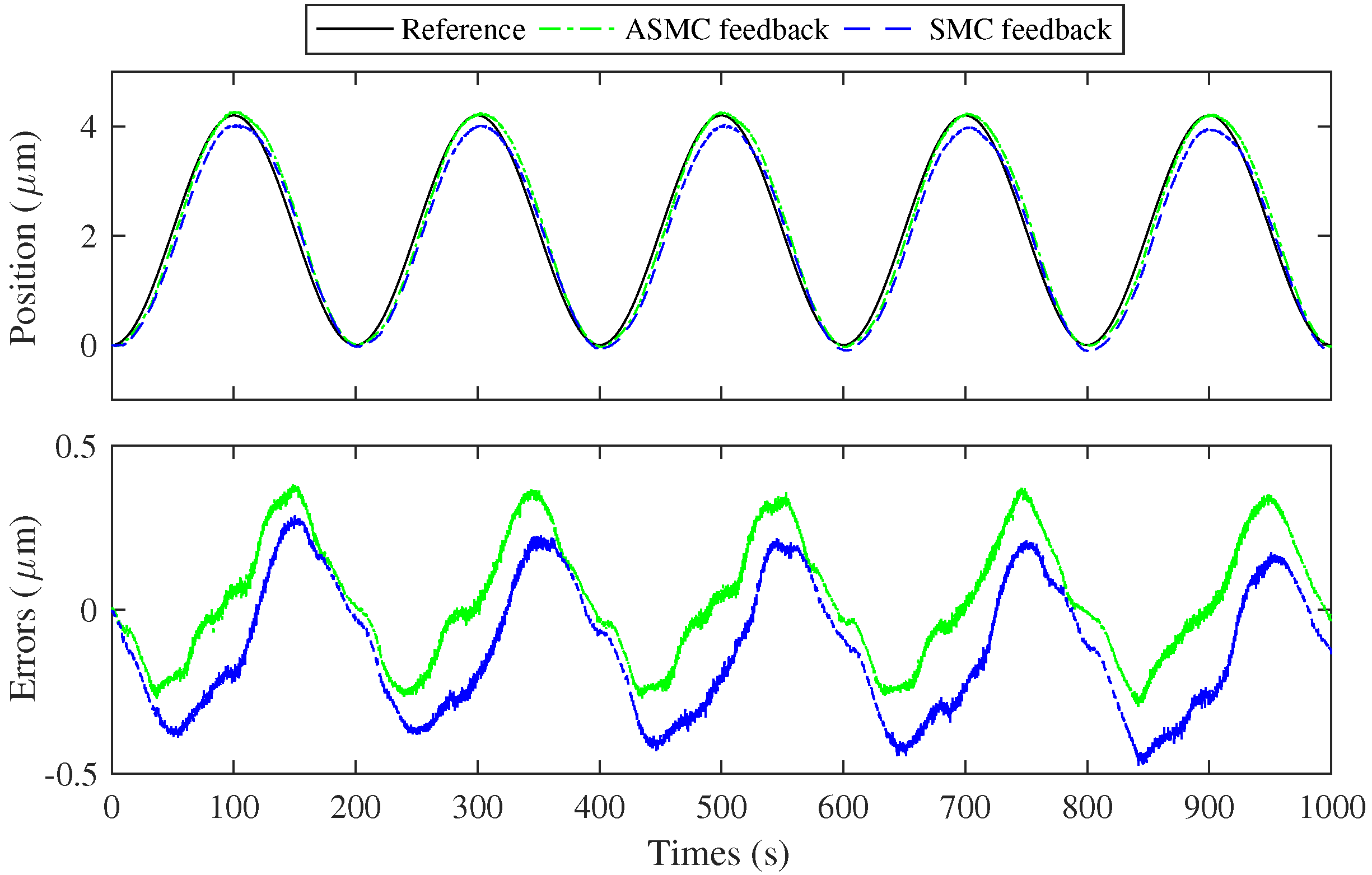
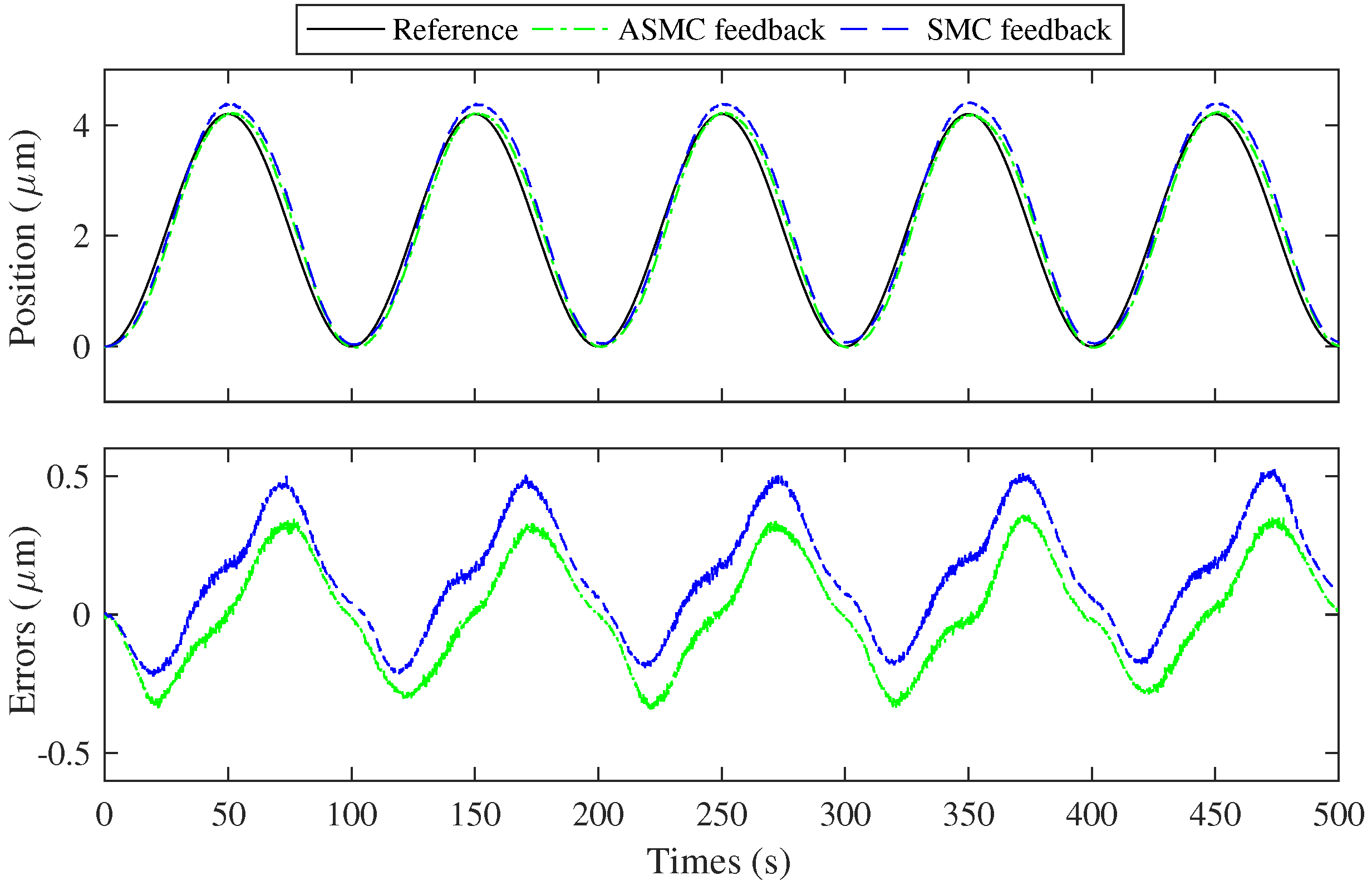
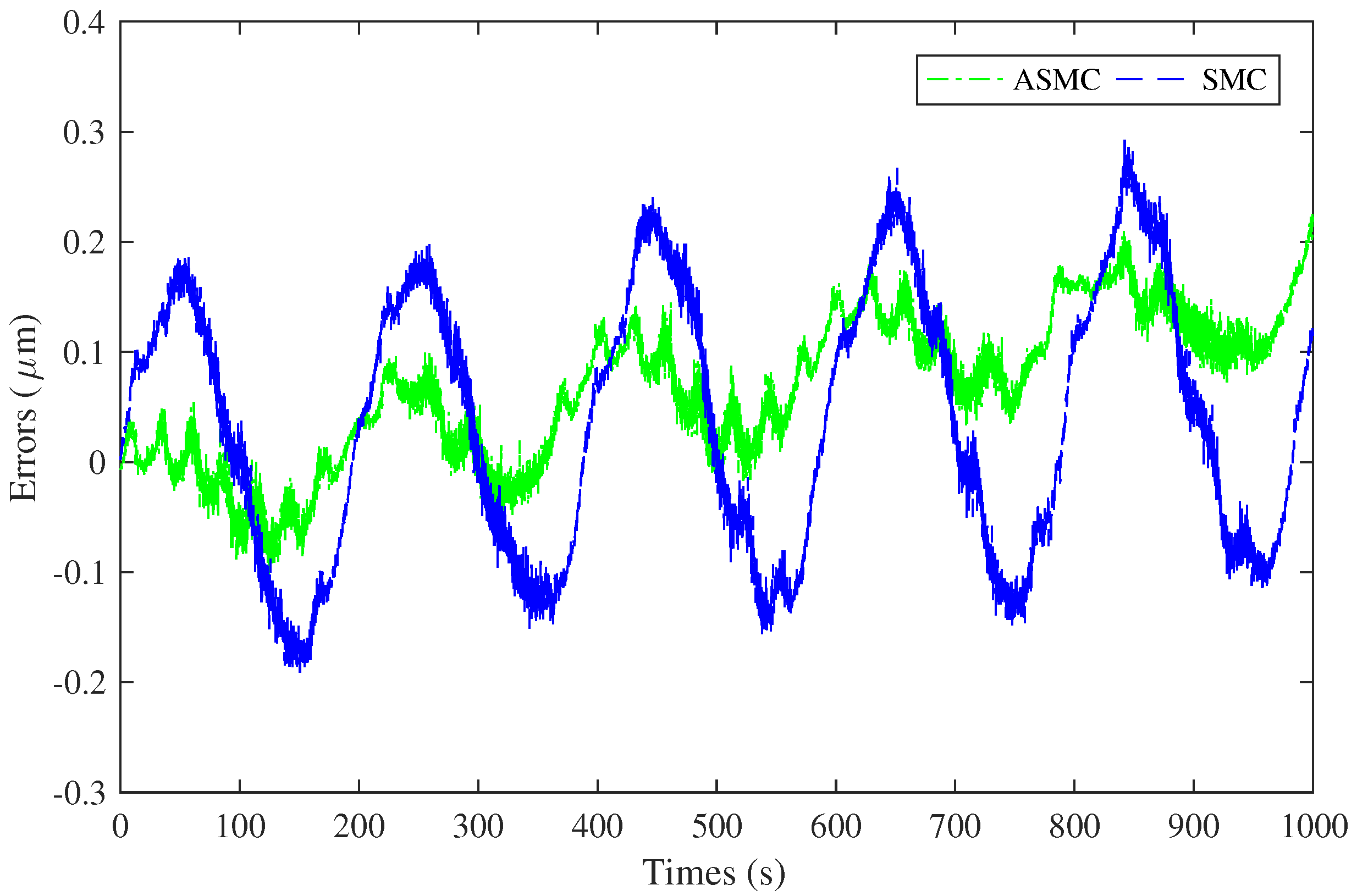
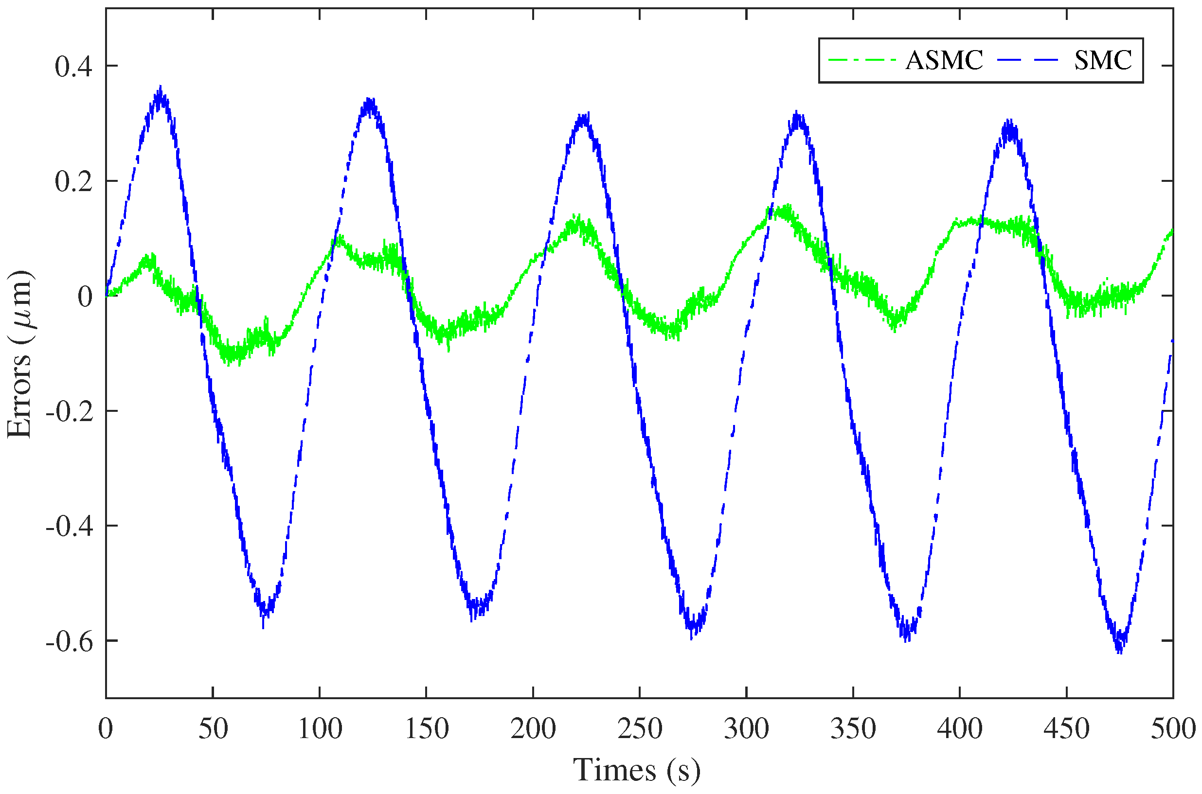
6.3. Tracking Error Testing Results

Table 3 provides a comparative analysis of sinusoidal tracking errors between the SMC scheme and ASMC scheme. The table delineates the maximum absolute error e m a x and root mean square error e r m s for each control method at 0.005 Hz and 0.010 Hz. These tracking errors are determined by the difference between the feedback displacement and the reference displacement expressed in micrometers μ m.
At a frequency of 0.005 Hz, the maximum absolute error e m a x for the SMC scheme is recorded at 0.4750 μ m. In comparison, the ASMC scheme demonstrates a lower error of 0.3822 μ m. It represents a reduction of 19.57 % in the maximum absolute error compared with the SMC scheme. Upon increasing the frequency to 0.010 Hz, the error for the SMC scheme escalates to 0.5260 μ m. In contrast, the ASMC scheme exhibits a lower error of 0.3596 μ m. This difference indicates a reduction of 31.67% in the maximum absolute error when using the ASMC scheme. Compared with the conventional SMC, the ASMC scheme effectively mitigates the maximum absolute error e m a x .
At the frequency of 0.005 Hz, the root mean square error e r m s for the SMC scheme is 0.2337 μ m. However, the ASMC scheme shows improved performance with an error of 0.1854 μ m, resulting in a 20.63% decrease. At the elevated frequency of 0.010 Hz, the SMC error increases to 0.2491 μ m, while the ASMC error is only 0.1967 μ m, indicating a 21.02% improvement with ASMC. Consistently, the ASMC scheme outperforms the SMC scheme with respect to e m a x , signifying a superior tracking accuracy.
These results underscore the superior performance of the ASMC scheme in terms of tracking accuracy. The ASMC scheme allows for a more precise response to system dynamics, leading to substantial reductions in both maximum absolute and root mean square errors.
Figure 6 and Figure 7 show the results of sinusoidal tracking with two different controllers at 0.005 Hz and 0.010 Hz, respectively. The graphical representation includes three distinct lines: the reference position is denoted by the black line. The green line corresponds to the feedback position under the ASMC scheme. And the blue line signifies the feedback position under the SMC scheme. However, error between the reference and feedback positions is observable. These errors can be ascribed to a confluence of factors:
(1)
System response time: Inherent delays in the system’s response to reference changes may lead to phase lag and subsequently increase errors. The communication time between the data acquisition card, motion control card, and the computer contributes to the system’s temporal delay.
(2)
Sensor limitations: The resolution and temporal responsiveness of sensors that ascertain the system’s feedback position is limited by the performance of the sensors. These limitations can lead to an imprecise representation of the system’s position.
(3)
Structural influences: Minimal variations in the structure during motion can impact the precision of strain gauge-based feedback displacement measurements. These minor fluctuations cause deviations in the strain gauge’s readings, although seemingly insignificant. As a result, the accuracy of the feedback signal is compromised.
(4)
Calibration inaccuracies: In the calibration process, it is commonly assumed that the system response is linear. However, the actual system are characterized by hysteresis. The deviation between the linearized calibration model and the nonlinearity system response consequently compromises the precision of the tracking performance.
The amplitude of the sinusoidal response is also subject to the factors. In summary, the system demonstrates commendable tracking capabilities. And the tracking capabilities can be improved by addressing the identified error caused by system response time, sensor limitations, structural influences, and calibration inaccuracies. The reduction in this error is particularly crucial for applications that require high-precision control. Then, the ASMC strategy stands out as a valuable scheme. It effectively delivers a robust solution for achieving the desired level of accuracy in tracking performance.
Figure 8 and Figure 9 depict the error between the feedback and actual displacements for two distinct control schemes at frequencies of 0.005 Hz and 0.010 Hz, respectively. The figures present two curves: one representing the ASMC scheme and the other the SMC scheme, both quantifying the error magnitudes. The ASMC curve is consistently beneath the SMC curve. It signifies that the ASMC scheme generally yields lower error levels.
A notable observation is the ASMC scheme’s effectiveness in reducing not only the overall error but also the error band—the range between maximum and minimum errors. At 0.005 Hz, the error band for the ASMC scheme is approximately 0.2 μ m, while for the SMC scheme, it is 0.4 μ m. At 0.010 Hz, the ASMC error band is about 0.2 μ m, and for the SMC scheme, it is 0.9 μ m. This significant narrowing of the error band by ASMC indicates its superior capacity to maintain a closer alignment between the actual and feedback positions. Thereby, it enhances the system’s stability and precision.

6.4. Discussion

This research integrates an ASMC scheme with strain gauge feedback for a piezoelectric nanopositioning stage. The integration confirms the scheme’s feasibility and demonstrates its efficacy in enhancing precision motion control. Compared with the conventional SMC scheme, a significant finding is the marked reduction in tracking errors. The ASMC scheme demonstrates superior performance due to its dynamic error suppression capabilities. Additionally, its adaptability to real-time system variations plays a crucial role. These features are essential for maintaining precise control, especially in the presence of uncertainties.
The research yields findings of substantial relevance to industrial applications. It introduces an advanced control solution with the capacity to enhance the performance of nanopositioning stages. However, the research also reveals a notable limitation: the system’s response speed is slow. This limitation leads to increased tracking errors. And this limitation highlights a critical area for future research. Enhancing the system’s response speed is essential. Focusing on this improvement will contribute to reducing errors and optimizing overall system performance.
The findings of this research not only validate the ASMC scheme’s feasibility but also suggest its potential for broad in the field of piezoelectric nanopositioning stages. The results indicate that this control scheme could influence the development and application of precision control systems. The integration of strain gauge feedback with the ASMC scheme offers a practical solution to enhance the performance of nanopositioning stages. This advancement could have implications for the automation equipment industry.

7. Conclusions

This paper presents an adaptive sliding mode control scheme based on strain gauge feedback for precise motion tracking control of a piezoelectric nanopositioning stage. Strain gauges measure the stage’s displacement, with the data being fed back into a closed-loop control system incorporating an SMC scheme to minimize motion errors. An adaptive control law is introduced to automatically adjust control gains, thereby reducing the range of tracking errors. The stability of the control strategy is theoretically substantiated through Lyapunov analysis. Tracking experiments conducted on the nanopositioning stage validate the control precision and stability of the proposed scheme. The experimental results demonstrate the effectiveness of the proposed control scheme in a piezoelectric-driven nanopositioning system. This work bridges the gap between mature sensor technology and advanced control algorithms. And it demonstrates the potential for integrating high-precision sensing with sophisticated control strategies to enhance the performance of piezoelectric nanopositioning systems. The scheme is easy to implement and has a low cost, making it conducive to the widespread application of piezoelectric ceramic technology in the field of precision motion control.

Author Contributions

Conceptualization, X.Z. (Xiaozhi Zhang); methodology, F.N.; software, C.M.; validation, J.S. and C.M.; formal analysis, K.W.; investigation, T.L., J.S. and K.W.; resources, T.L. and X.Z. (Xiaozhi Zhang); data curation, K.W. and C.M.; writing—original draft preparation, X.Z. (Xianfeng Zeng); writing—review and editing, F.N.; supervision, K.W.; project administration, X.Z. (Xiaozhi Zhang). All authors have read and agreed to the published version of the manuscript.

Funding

This research was funded by Zhuhai Industry-Academia Cooperation R&D Project grant number 2320004002732.

Data Availability Statement

The original contributions presented in the study are included in the article; further inquiries can be directed to the corresponding author.

Conflicts of Interest

Author Tengfei Li was employed by the company Zhuhai Huaya Machinery Technology Co., Ltd. Author Changchao Mo was employed by the company Zhuhai Huaya Machinery Technology Co., Ltd. Author Jiaqiu Su was employed by the company Zhuhai Huaya Machinery Technology Co., Ltd. Author Kaihong Wei was employed by the company Zhuhai Huaya Machinery Technology Co., Ltd. The remaining authors declare that the research was conducted in the absence of any commercial or financial relationships that could be construed as a potential conflict of interest.

References

  1. Guo, D.; Nagel, W.S.; Clayton, G.M.; Leang, K.K. Spatial-Temporal Trajectory Redesign for Dual-Stage Nanopositioning Systems With Application in AFM. IEEE/ASME Trans. Mechatron. 2020, 25, 558–569. [Google Scholar] [CrossRef]
  2. Li, L.; Li, C.X.; Gu, G.; Zhu, L. Modified Repetitive Control Based Cross-Coupling Compensation Approach for the Piezoelectric Tube Scanner of Atomic Force Microscopes. IEEE/ASME Trans. Mechatron. 2019, 24, 666–676. [Google Scholar] [CrossRef]
  3. Prabhu, P.; Rao, M. Investigations on piezo actuated micro XY stage for vibration-assisted micro milling. J. Micromech. Microeng. 2021, 31, 065007. [Google Scholar] [CrossRef]
  4. Zhao, D.; Zhu, Z.; Huang, P.; Guo, P.; Zhu, L.; Zhu, Z. Development of a piezoelectrically actuated dual-stage fast tool servo. Mech. Syst. Signal Process. 2020, 144, 106873. [Google Scholar] [CrossRef]
  5. Chang, Q.; Liu, Y.; Deng, J.; Zhang, S.; Chen, W. Design of a precise linear-rotary positioning stage for optical focusing based on the stick-slip mechanism. Mech. Syst. Signal Process. 2022, 165, 108398. [Google Scholar] [CrossRef]
  6. Makarem, S.; Delibas, B.; Koc, B. Data-Driven Tuning of PID Controlled Piezoelectric Ultrasonic Motor. Actuators 2021, 10, 148. [Google Scholar] [CrossRef]
  7. Fang, J.; Zhang, L.; Long, Z.; Wang, M.Y. Fuzzy Adaptive Sliding Mode Control for the Precision Position of Piezo-Actuated Nano Positioning Stage. Int. J. Precis. Eng. Manuf. 2018, 19, 1447–1456. [Google Scholar] [CrossRef]
  8. Kong, L.; Li, D.; Zou, J.; He, W. Neural Networks Based Learning Control for a Piezoelectric Nanopositioning System. IEEE/ASME Trans. Mechatron. 2020, 25, 2904–2914. [Google Scholar] [CrossRef]
  9. Baziyad, A.G.; Ahmad, I.; Bin Salamah, Y. Precision Motion Control of a Piezoelectric Actuator via a Modified Preisach Hysteresis Model and Two-Degree-of-Freedom H-Infinity Robust Control. Micromachines 2023, 14, 1208. [Google Scholar] [CrossRef]
  10. Ni, L.; Chen, J.; Chen, G.; Zhao, D.; Wang, G.; Aphale, S.S. An explainable neural network integrating Jiles-Atherton and nonlinear auto-regressive exogenous models for modeling universal hysteresis. Eng. Appl. Artif. Intell. 2024, 136, 108904. [Google Scholar] [CrossRef]
  11. Zhu, W.L.; Zhu, Z.; Guo, P.; Ju, B.F. A novel hybrid actuation mechanism based XY nanopositioning stage with totally decoupled kinematics. Mech. Syst. Signal Process. 2018, 99, 747–759. [Google Scholar] [CrossRef]
  12. Xi, X.; Clancy, T.; Wu, X.; Sun, Y.; Liu, X. A MEMS XY-stage integrating compliant mechanism for nanopositioning at sub-nanometer resolution. J. Micromech. Microeng. 2016, 26, 025014. [Google Scholar] [CrossRef]
  13. Sun, W.; Lin, X.; Huang, L.; Mu, D.; Zhang, H. Distributed sliding mode control for reactive power sharing in an islanded microgrid. Electr. Power Syst. Res. 2024, 231, 110342. [Google Scholar] [CrossRef]
  14. Li, Z.; Li, L.; Zhang, J.; Feng, W. System modeling and sliding mode control of fast steering mirror for space laser communication. Mech. Syst. Signal Process. 2024, 211, 111206. [Google Scholar] [CrossRef]
  15. Wang, G.; Wang, B.; Zhang, C. Fixed-Time Third-Order Super-Twisting-like Sliding Mode Motion Control for Piezoelectric Nanopositioning Stage. Mathematics 2021, 9, 1770. [Google Scholar] [CrossRef]
  16. Medina, L.; Guerra, G.; Herrera, M.; Guevara, L.; Camacho, O. Trajectory tracking for non-holonomic mobile robots: A comparison of sliding mode control approaches. Results Eng. 2024, 22, 102105. [Google Scholar] [CrossRef]
  17. Khodaverdian, M.; Hajshirmohamadi, S.; Hakobyan, A.; Ijaz, S. Predictor-based constrained fixed-time sliding mode control of multi-UAV formation flight. Aerosp. Sci. Technol. 2024, 148, 109113. [Google Scholar] [CrossRef]
  18. Chang, Y.; Wang, A.; Yan, H.; Zhai, G.; Huang, W. Adaptive complementary sliding mode control of ship course under environmental disturbance. Ocean Eng. 2024, 312, 119016. [Google Scholar] [CrossRef]
  19. Qu, C.; Cheng, L.; Gong, S.; Huang, X. Dynamic-matching adaptive sliding mode control for hypersonic vehicles. Aerosp. Sci. Technol. 2024, 149, 109159. [Google Scholar] [CrossRef]
  20. Chen, L.; Ding, S.; Zhao, J.; Gao, J.; Chen, H. Temperature regulation for liquid-cooled fuel cell based on adaptive sliding mode control. Int. J. Hydrogen Energy 2024, 68, 1097–1107. [Google Scholar] [CrossRef]
  21. Guo, X.; Wang, H.; Liu, H. Adaptive sliding mode control with disturbance estimation for hydraulic actuator systems and application to rock drilling jumbo. Appl. Math. Model. 2024, 136, 115637. [Google Scholar] [CrossRef]
  22. Li, J.; Zhao, Z.; Qin, X. Adaptive sliding mode control using a novel fully feedback recurrent neural network for quad-rotor UAVs. Neurocomputing 2024, 610, 128592. [Google Scholar] [CrossRef]
  23. Chen, L.; Wu, Z.; Xu, Q. Novel Adaptive Global Observer-Based Sliding Mode Control of a 2-DOF Piezoelectric Nanopositioning System. IEEE Trans. Autom. Sci. Eng. 2024, 1–14. [Google Scholar] [CrossRef]
  24. Chen, X.; Hisayama, T. Adaptive Sliding-Mode Position Control for Piezo-Actuated Stage. IEEE Trans. Ind. Electron. 2008, 55, 3927–3934. [Google Scholar] [CrossRef]
  25. Ming, M.; Liang, W.; Feng, Z.; Ling, J.; Al Mamun, A.; Xiao, X. PID-type sliding mode-based adaptive motion control of a 2-DOF piezoelectric ultrasonic motor driven stage. Mechatronics 2021, 76, 102543. [Google Scholar] [CrossRef]
  26. Xu, Q. Precision Motion Control of Piezoelectric Nanopositioning Stage With Chattering-Free Adaptive Sliding Mode Control. IEEE Trans. Autom. Sci. Eng. 2017, 14, 238–248. [Google Scholar] [CrossRef]
  27. Qin, C.; Zhang, Z.; Fang, Q. Adaptive Backstepping Fast Terminal Sliding Mode Control With Estimated Inverse Hysteresis Compensation for Piezoelectric Positioning Stages. IEEE Trans. Circuits Syst. II Express Briefs 2024, 71, 1186–1190. [Google Scholar] [CrossRef]
  28. Bazaei, A.; Boudaoud, M.; Ettefagh, M.H.; Chen, Z.; Régnier, S. Non-Collocated Displacement Sensing by Semiconductor Strain Gauges in Differentially Piezo-Driven Nanopositioners. IEEE Sens. J. 2021, 21, 9690–9697. [Google Scholar] [CrossRef]
  29. Li, P.Z.; Zhang, D.F.; Lennox, B.; Arvin, F. A 3-DOF piezoelectric driven nanopositioner: Design, control and experiment. Mech. Syst. Signal Process. 2021, 155, 107603. [Google Scholar] [CrossRef]
  30. Yin, Z.; Qin, R.; Du, H.; Zhou, W.; Sun, J.; Sun, D.; Liu, Y. Design and Parameter Identification for a Positioning Platform with a Large Stroke and High Precision for Segmented Mirrors. Micromachines 2023, 14, 713. [Google Scholar] [CrossRef]
  31. Bazaei, A.; Boudaoud, M.; Hemmasian Ettefagh, M.; Chen, Z.; Régnier, S. Displacement Sensing by Piezoelectric Transducers in High-Speed Lateral Nanopositioning. IEEE Sens. J. 2019, 19, 9156–9165. [Google Scholar] [CrossRef]
  32. Jin, T.; Luo, S.; Le, Y.; Wu, J.; Lei, L.; Zhang, B. Design and analysis of a low crosstalk error nested structure two-dimensional micro-displacement stage. Adv. Mech. Eng. 2021, 13, 16878140211014061. [Google Scholar] [CrossRef]
  33. Reverter, F. A Tutorial on Mechanical Sensors in the 70th Anniversary of the Piezoresistive Effect. Sensors 2024, 24, 3690. [Google Scholar] [CrossRef]
  34. Mitura, A.; Brunetti, M.; Kloda, L.; Romeo, F.; Warminski, J. Experimental nonlinear dynamic regimes for energy harvesting from cantilever bistable shells. Mech. Syst. Signal Process. 2024, 206, 110890. [Google Scholar] [CrossRef]
  35. Ajnada, T.; Bernard, Y.; Daniel, L. Snap-through of a bistable beam using piezoelectric actuation. J. Intell. Mater. Syst. Struct. 2024, 35, 1137–1148. [Google Scholar] [CrossRef]
  36. Zhang, Z.; Chen, L.W.; Xu, Z.D. Snap-through behavior of bistable beam with variable sections: Mechanical model and experimental study. Smart Mater. Struct. 2022, 31, 105004. [Google Scholar] [CrossRef]
Figure 1. The 3D model of the piezoelectric nanoposition stage.
Actuators 14 00079 g001
Figure 2. Experimental setup of the piezoelectric nanopositioning stage.
Actuators 14 00079 g002
Figure 3. Block diagram of the proposed ASMC scheme.
Actuators 14 00079 g003
Figure 4. Calibration results of strain gauge feedback voltage and measured displacement.
Actuators 14 00079 g004
Figure 5. Resolution ratio test results.
Actuators 14 00079 g005
Figure 6. The results of sinusoidal curve tracking with a frequency of 0.005 Hz.
Actuators 14 00079 g006
Figure 7. The results of sinusoidal curve tracking with a frequency of 0.010 Hz.
Actuators 14 00079 g007
Figure 8. Error between feedback displacement and actual displacement at 0.005 Hz.
Actuators 14 00079 g008
Figure 9. Error between feedback displacement and actual displacement at 0.010 Hz.
Actuators 14 00079 g009
Table 1. Parameters of dynamics model.
ParameterValue
m0.05 kg
b0.001 Ns/ μ m
k24.67 N/ μ m
d24.685 N/V
Table 2. Parameters of control scheme.
ParameterSMCASMC
c4848
p1010
ε 0.10.1
Δ1 × 10 5 1 × 10 5
λ -0.1
Table 3. Sinusoidal tracking error comparison for SMC and ASMC schemes.
ErrorsSMCASMC
e m a x  ( μ m)0.005 Hz0.47500.3822
0.010 Hz0.52600.3596
e r m s  ( μ m)0.005 Hz0.23370.1854
0.010 Hz0.24910.1967
Disclaimer/Publisher’s Note: The statements, opinions and data contained in all publications are solely those of the individual author(s) and contributor(s) and not of MDPI and/or the editor(s). MDPI and/or the editor(s) disclaim responsibility for any injury to people or property resulting from any ideas, methods, instructions or products referred to in the content.

