Article

Efficient and High-Precision Method of Calculating Maximum Singularity-Free Space in Stewart Platform Based on K-Means Clustering and CNN-LSTM-Attention Model

1
School of Mechanical Science and Engineering, Huazhong University of Science and Technology, Wuhan 430074, China
2
Huazhong Institute of Electro-Optics-Wuhan National Laboratory for Optoelectronics, Wuhan 430223, China
3
Sichuan Precision and Ultra-Precision Machining Engineering Technology Center, Chengdu 610200, China
*
Authors to whom correspondence should be addressed.
Actuators 2025, 14(2), 74; https://doi.org/10.3390/act14020074
Submission received: 29 December 2024 / Revised: 29 January 2025 / Accepted: 4 February 2025 / Published: 6 February 2025
(This article belongs to the Section Precision Actuators)

Abstract

:
The determination of maximum singularity-free space is critical to structural design and motion control strategy in the Stewart platform. Nevertheless, in practical applications, there exist several limitations such as computational efficiency, calculation precision, and the reliability of computational results. To overcome those shortcomings, this work proposes an efficient and high-precision method for computing the maximum singularity-free space within the Stewart platform. Firstly, apply K-Means clustering to group the variables, including the range, mean, and standard deviation of driving rod lengths, and the clustering centroids and extreme rod lengths collectively form a set of scenarios to avoid large-scale searching. An additional sorting methodology with a specific parameter is proposed for sorting the aforementioned scenarios in descending order and detecting singular-prone cases. Secondly, compute the initial solution for maximum singularity-free length without gimbal lock through an analytical solution formula, enabling reduction in the search scope. Thirdly, introduce a novel scaling factor to resolve the problem of dimensional inconsistency between rotation and translation within the Jacobian matrix using dual quaternions, and determine the singularity based on the determinant of the newly proposed Jacobian matrix. Finally, employ a CNN-LSTM-Attention model for a secondary verification procedure, specifically targeting the challenge of singularities encountered when solving the forward kinematics of the Stewart platform using zero-position values. The experiments demonstrate that the accelerated discretization method for maximum singularity-free joint space and workspace is applicable to devices with diverse geometric configurations. For two practical Stewart platforms, compared with two conventional methods, this method improves computational efficiency and precision significantly. The computation time of the first platform is reduced by 97.54% and 98.07% respectively, while that of the second platform is cut by 80.84% and 81.80% respectively. In terms of precision, the first platform demonstrates 95.83% and 78% improvement respectively, and the second platform attains 99.99% improvement over two conventional methods.

1. Introduction

With the rapid development of industrial automation and robotics technology, parallel mechanisms, constituting a significant subdivision within the realm of robotics, have received considerable attention on account of their distinctive structural advantages and wide application prospects. Due to the remarkable features, specifically high rigidity, elevated precision and a superior load-to-weight ratio, the Stewart platform, serving as a pivotal 6-degree-of-freedom (6-DOF) parallel mechanism, has manifested substantial application potential across diverse fields like aerospace, precision manufacturing, and simulator realms. Nevertheless, the singularity of the Stewart platform in specific situations has always been one of the key factors restricting the performance and wide application. For the Stewart platform, singularity refers to the situation where the determinant of Jacobian matrix is zero or close to zero under certain configurations. When singularity occurs, the mechanism loses the control stability and may even suffer damage or experience task failure. Therefore, exploring the maximum singularity-free joint space and workspace of the Stewart platform is highly significant for ensuring the stability of the mechanism during motion.
In the existing works, the determination of singularity-free space often failed to simultaneously consider both the position and orientation of the mobile platform [1,2,3,4,5,6,7]. In fact, considering only the singularity of the position or solely focusing on the singularity of orientation is inappropriate because both of them are fundamentally interconnected in determining the overall spatial configuration and functionality of the system. Additionally, using a weighting coefficient to consider the singularity-free spaces associated with only position and only orientation, and thereby correlate position and orientation, is flawed due to the lack of a clear physical meaning [8]. Considering the position and orientation simultaneously, Pernkopf et al. [9] first proposed the method of calculating maximal singularity-free workspace of the Stewart platform. Nonetheless, that method has low computational efficiency. The researches on the computation of singularity-free space were mainly conducted based on Euler angles [10,11,12,13] and unit quaternion [14,15,16,17].
The existing methods of computing the singularity-free space are categorized as geometrical methods, numerical methods, and discretization methods. The geometric method is a way to determine the position and orientation for a parallel mechanism to avoid singular configurations by analyzing the kinematic equations and geometric constraint relations of the parallel mechanism. A common limitation of the geometrical method is the disregard for mechanical interfaces and other physical constraints [18,19,20], which is inapplicable to some geometric configuration and does not simultaneously consider position and orientation. Moreover, Li et al. [21] employed a screw-theory-based geometrical approach, which yielded two Jacobian matrices, and subsequently analyzed their singular conditions. The time complexity of geometrical method is O ( 1 ).
Numerical methods comprehensively incorporate the kinematic equations of the parallel mechanism, structural constraint conditions, and the variation ranges of leg lengths. The objective is to solve the position and orientation ranges where the mechanism can evade singular configurations, thus ascertaining the singularity-free workspace. An evolutionary strategy was used by Liu et al. [22] to detect the singularity in the desired reachable workspace of the 6-UCU parallel manipulator. Assuming that the number of iterations, the population size, and the gene length per individual in Ref. [22] is M 1 , N 1 , K 1 , respectively, then the time complexity is O ( M 1 N 1 K 1 ). Merlet [23] adopted numerical techniques to determine the singularity-free workspace of the Stewart platform, and the time complexity O ( N 6 ) where the number of equally divided segments in the interval analysis method for each dimension was N . Kaloorazi et al. [24] used the interval analysis method to compute singularity-free circles in the position workspace of parallel mechanisms with the time complexity O ( N 3 ) , where the number of equally divided parts is N . Abbasnejad et al. [25] computed singularity-free space by using the particle swarm optimization technique, and the time complexity was O ( M 2 N 2 K 2 ), where the number of iterations, the swarm size, and the dimension of each particle was M 2 , N 2 , and K 2 , respectively. Nag et al. [26] solved the problem of finding a sphere free of singularities of the Stewart platform manipulators in either the position or the orientation workspace with numerical approaches. When the sphere is uniformly sampled into N segments, the time complexity is O ( N 3 ). Nevertheless, when multiple solutions exist, the numerical method is not applicable due to the difficulties in selecting the appropriate solution from all possible ones.
The discrete method involves discretizing the workspace of the Stewart platform into a set of points. For each of these points, the kinematic equations and the Jacobian matrix of the platform are evaluated. The determination of whether the corresponding point lies within the singularity-free space is made by checking the determinant of the Jacobian matrix. Most discrete methods do not take into account the determination of singularity by the initial values of the Newton–Raphson method in the procedure of forward kinematics. One can assume that the number of iterations is M . Furthermore, one can assume that within the discretization method, each active joint space, as well as position and orientation, is divided into N segments. Wang et al. [27] proposed a unified numerical method to solve the reachable and dexterous workspace boundary problems of parallel robots, and the time complexity is O ( N 3 ). Nevertheless, only three-direction DOFs are considered. Cheng et al. [28] obtained eight equivalent equations, which can be used to analyze the singularity of the 6-SPS parallel mechanism, and the time complexity is O ( N 3 ) with a designed position or orientation. Ding [29] searched for all the discrete points within the feasible space with a predefined step size and provided a detailed exploration of the constraints and optimization strategies for maximizing the workspace of a spatially isotropic Stewart platform with the time complexity of O ( N 3 ) . Nevertheless, that method only takes into account the position or orientation space. Yang et al. [30] proposed a discretization method for calculating the dimensionless Jacobian matrix of a 6-DOF parallel robot using dual quaternions (DM-DQ), and the singularity-free joint space and workspace were simultaneously calculated. The DM-DQ method had the time complexity of O ( M N 6 ) . Nevertheless, the aforementioned methods still failed to address the problem of computation time and calculation precision. The methods [27,28,29,30] were conducted based on unit quaternion. The comparison of the existing algorithms for computing singularity-free space is illustrated in Table 1.
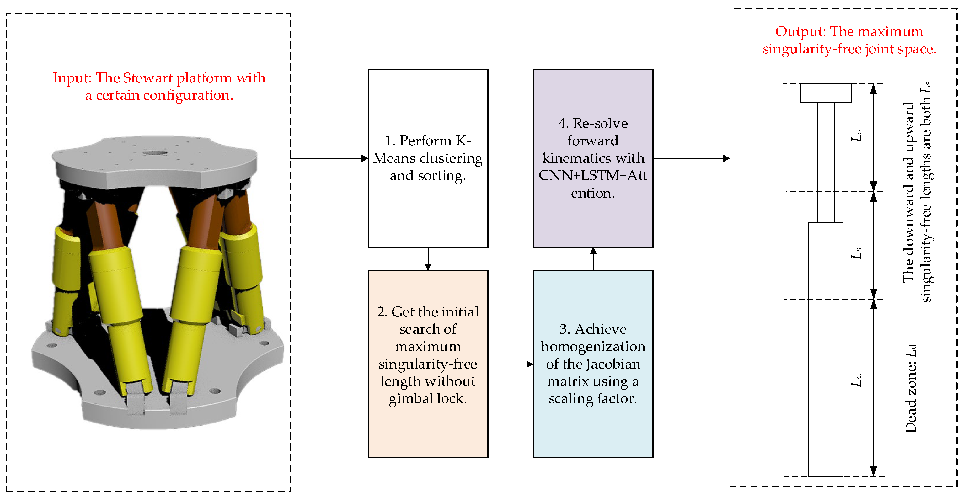
To overcome those deficiencies and obtain the maximum singularity-free joint space and workspace in a more rapid, precise, and reliable manner, this work proposes an efficient and high-precision method of calculating maximum singularity-free space in the Stewart platform based on K-Means clustering and the CNN-LSTM-Attention model, avoiding the singularity of the Jacobian matrix in the case of inappropriate initial values in the numerical part. Firstly, K-Means clustering and sorting operations are carried out. These operations can reduce the computational load without affecting the feature diversity. Secondly, the initial search for the maximum singularity-free length without gimbal lock is conducted. When the gimbal lock appears, the loss of DOFs may reduce the rank of the Jacobian matrix, thereby driving the determinant of Jacobian matrix to zero or near-zero values and triggering singularity. Thirdly, the homogenization of the Jacobian matrix is accomplished with a scaling factor. When the product of the determinants of the newly constructed Jacobian matrices corresponds to the natural position and a specific posture is less than or equal to zero, the occurrence of singularity in that situation is indicated. Finally, forward kinematics is re-solved using the CNN-LSTM-Attention model. The contributions and novelties of this work are presented as follows.
  • This work proposes the K-Means clustering and sorting approach to efficiently identify the desired space, ensuring the diversity of rod length combinations while improving computational efficiency, compared with the previous methods.
  • This work puts forward an accurate analytical approach without the gimbal lock, avoiding the emergence of complex kinematic solutions and the deterioration of control accuracy and stability in previous works.
  • This work proposes a new dimension scaling factor to handle the problem of inconsistent dimensions between rotation and translation. The newly constructed Jacobian matrix is utilized to determine singularity.
  • This work utilizes the CNN-LSTM-Attention model to tackle singularities in the forward kinematics caused by zero-position values, solving the problem of unreliability in the search procedure of the previous works.
The structure of this paper is arranged as follows. Section 2 presents the overview of the proposed method. Section 3 introduces the mathematical model of the Stewart platform. Section 4 explores the discretization method for computing the maximum singularity-free joint space and workspace. Section 5 presents experiments to validate the method’s efficiency, precision and reliability. Section 6 concludes with a summary.

2. Overview

Aiming at universally obtaining the maximum singularity-free joint space of the Stewart platform, this work proposes a discretization method based on K-Means clustering and the CNN-LSTM-Attention model. The overview of the proposed method is shown in Figure 1, and the detailed steps are elaborated as follows.
(1)
Perform K-Means clustering and sorting. Dividing each driving rod length equally and then performing permutations and combinations on rod lengths are time-consuming and unnecessary procedures. Hence, the clustering and sorting methodologies are applied in this work. That operation includes the extraction of characteristics from all conceivable permutations and combinations, and significantly boosts computational efficiency.
(2)
Obtain the initial search of maximum singularity-free length without gimbal lock. When searching for the maximum non-singular driving rod length from a very large numerical range, the procedure can be rather unfocused and detrimental to computational efficiency. This paper addresses the problem of determining an initial search value for identifying the maximum singularity-free workspace, taking into account the issue of gimbal lock.
(3)
Achieve homogenization of the Jacobian matrix by using a scaling factor. The homogenization of the Jacobian matrix serves as a means to enhance numerical stability, guarantee uniform scaling, and promote a more facile interpretation and analysis of the system’s behavior, thereby collectively fostering more dependable and efficient computations.
(4)
Re-solve the singularity-free space with the CNN-LSTM-Attention model. When applying Newton–Raphson method to detect the occurrence of singularities, the results are frequently affected by the initial value. To prevent singularities in the Jacobian matrix arising from inappropriate initial values, the CNN-LSTM-Attention model needs to re-estimate the value for singular operating conditions, ensuring the reliability of the maximum singularity-free space.

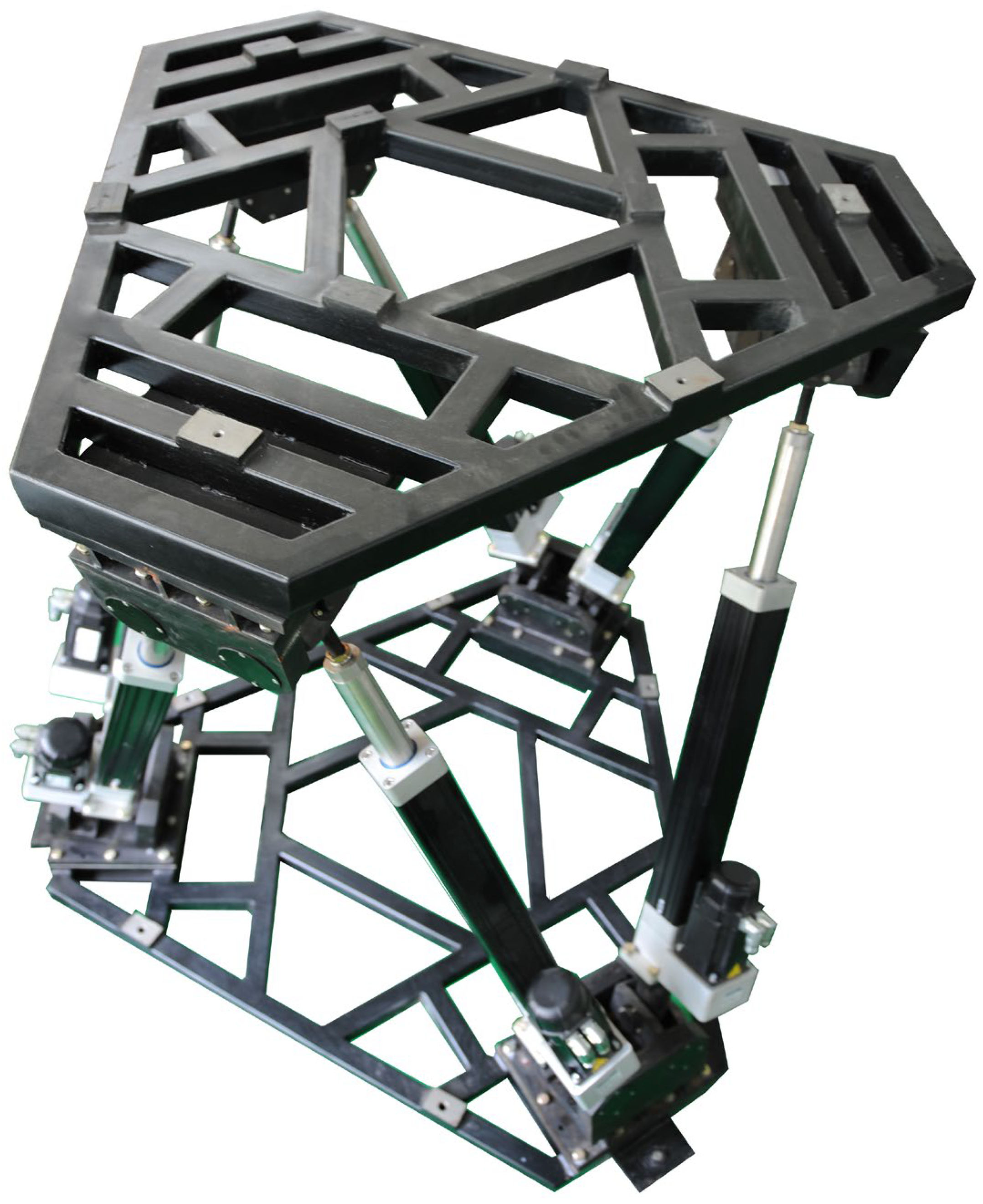
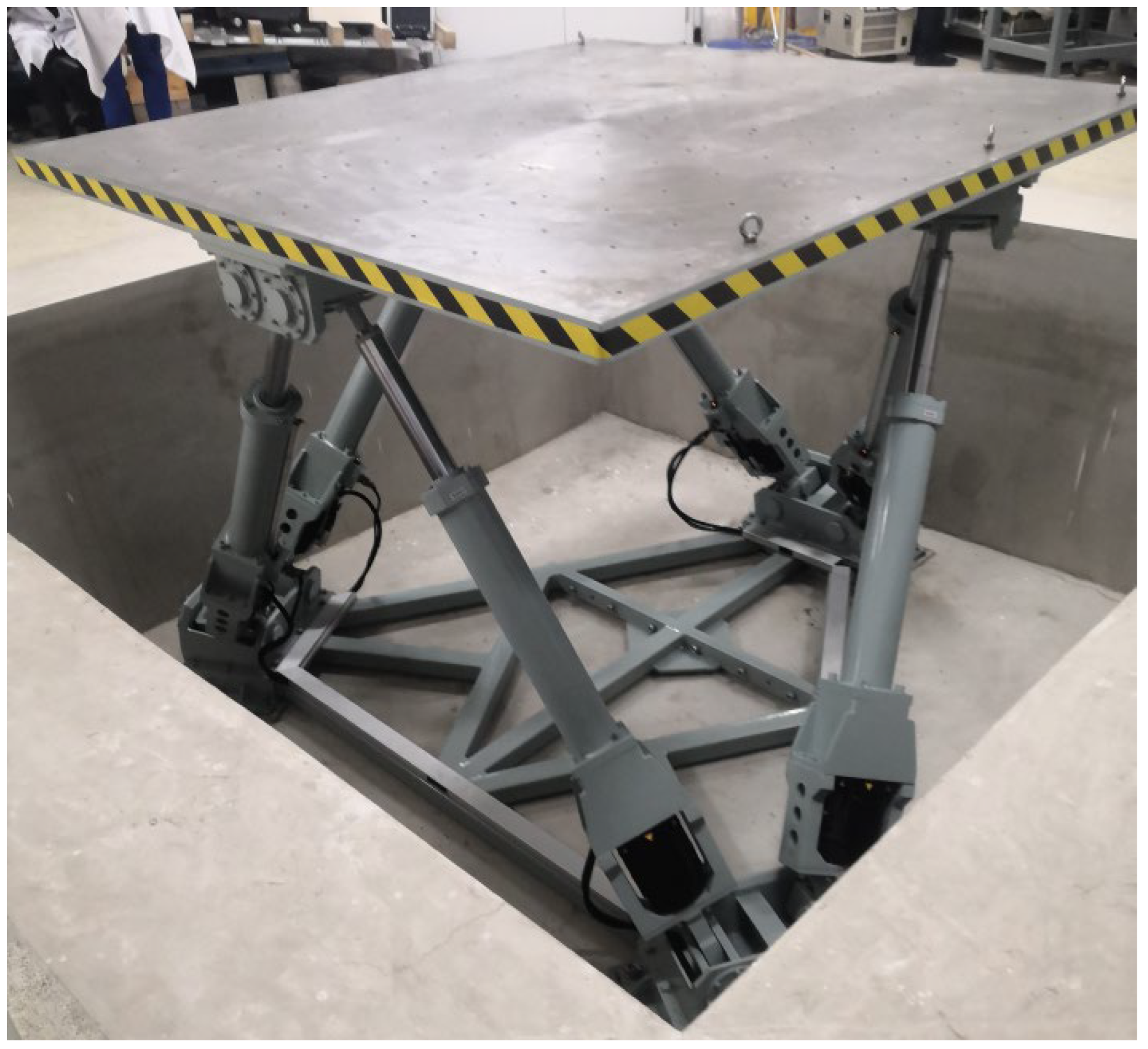
3. The Mathematical Model of the Stewart Platform

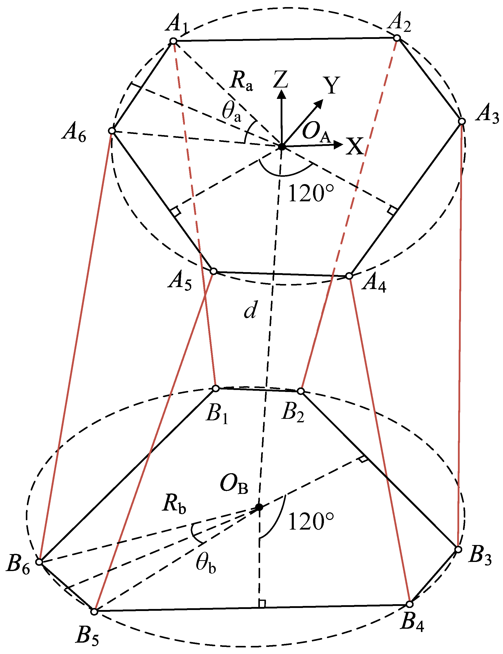
The Stewart platform is composed of a moving platform, a fixed platform, and electric cylinders. Each joint point on the moving platform and fixed platform are denoted as A i ( i = 1 , , 6 ) and B i ( i = 1 , , 6 ). The Stewart platform usually has five structural parameters: the moving and fixed platform radii are R a and R b , the angles are θ a and θ b , and the distance between the moving and fixed platforms is d when the Stewart platform is in the initial assembly configuration.
As shown in Figure 2, the joint points on the moving and fixed platform are usually on a circle. The coordinates of joint points on the moving platform are given as follows. In Figure 2, the solid red lines represent the active joints, and the solid black lines represent the moving platform and the fixed platform.
A = R a s i n π 3 θ a 2 R a s i n π 3 θ a 2 R a c o s π 6 θ a 2 R a sin θ a 2 R a sin θ a 2 R a cos π 6 θ a 2 R a c o s π 3 θ a 2 R a c o s π 3 θ a 2 R a s i n π 6 θ a 2 R a cos θ a 2 R a cos θ a 2 R a sin π 6 θ a 2 0 0 0 0 0 0
The coordinates of joint points on the fixed platform are given as follows.
B = R b sin θ b 2 R b sin θ b 2 R b c o s π 6 θ b 2 R b s i n π 3 θ b 2 R b s i n π 3 θ b 2 R b c o s π 6 θ b 2 R b cos θ b 2 R b cos θ b 2 R b s i n π 6 θ b 2 R b c o s π 3 θ b 2 R b c o s π 3 θ b 2 R b s i n π 6 θ b 2 d d d d d d
When dealing with forward kinematics, the position and orientation are determined in accordance with the lengths of the rods. Conversely, during the solution of the inverse kinematics, the rod length is calculated based on the position and orientation. In contrast to the forward kinematics issue, the inverse kinematics problem is comparatively less complex.
The inverse kinematics problem involves calculating the actuator lengths based on a given pose Q of the moving platform. Let α , β , and γ be the angles of rotation around the three axes of the Cartesian coordinate system, representing the pitch, roll, and yaw angles, respectively. Meanwhile, let x , y , and z be the translational displacements along these axes, corresponding to surge, sway, and heave, respectively.
Q = [ α ,   β ,   γ , x , y , z ] T
R denotes the rotation matrix expressed in the Euler angle representation of pitch–roll–yaw, as detailed below.
R = c o s β c o s γ s i n α s i n β c o s γ c o s α s i n γ c o s α s i n β c o s γ + s i n α s i n γ c o s β s i n γ s i n α s i n β s i n γ + c o s α s i n γ c o s α s i n β s i n γ s i n α c o s γ s i n β s i n α c o s β c o s α c o s β
With the reference frame fixed, the coordinates of the joint points on the moving platform and fixed platform are a i and b i ( i = 1,…,6), and six electric actuator vectors L i ( i = 1,…,6) can be expressed as follows.
L i = R a i b i ,     i = 1 , , 6
Techniques for rigid-body rotation include direction cosines and quaternions. Direction cosines need nine parameters, while quaternions only need four, making quaternions more concise. Compared with direction-cosine-based methods, quaternions greatly reduce trigonometric calculation complexity. Dual quaternions describe full rigid-body motion in a unified and efficient manner, thereby simplifying computations and providing a more straightforward approach compared to direction cosines.
A dual quaternion is a mathematical construct consisting of an even number of elements, where both the real and dual components are quaternions. In contrast to standard quaternions that can only represent spatial rotations, dual quaternions have the ability to describe any combination of spatial rotation and translation.
ζ and h form a dual quaternion λ .
λ = ζ + ε h
where ε is a dual unit, and ε 2 = 0 . Inside, ζ = [ ζ 0 , ζ 1 , ζ 2 , ζ 3 ] , h = [ h 0 , h 1 , h 2 , h 3 ] .
ζ = 1 ζ T h = 0
The homogeneous rotation matrix T can be expressed by dual quaternions as follows.
T = 2 ζ 0 2 + 2 ζ 1 2 1 2 ζ 1 ζ 2 2 ζ 0 ζ 3 2 ζ 1 ζ 3 + 2 ζ 0 ζ 2 2 ( ζ 0 h 1 ζ 1 h 0 + ζ 2 h 3 ζ 3 h 2 ) 2 ζ 1 ζ 2 + 2 ζ 0 ζ 3 2 ζ 0 2 + 2 ζ 2 2 1 2 ζ 2 ζ 3 2 ζ 0 ζ 1 2 ( ζ 0 h 2 ζ 1 h 3 ζ 2 h 0 + ζ 3 h 1 ) 2 ζ 1 ζ 3 2 ζ 0 ζ 2 2 ζ 0 ζ 3 + 2 ζ 0 ζ 1 2 ζ 0 2 + 2 ζ 3 2 1 2 ( ζ 0 h 3 + ζ 1 h 2 ζ 2 h 1 ζ 3 h 0 ) 0 0 0 1

4. Discretization Method for Calculating Maximum Singularity-Free Joint Space and Workspace

4.1. K-Means Clustering Followed by Sorting

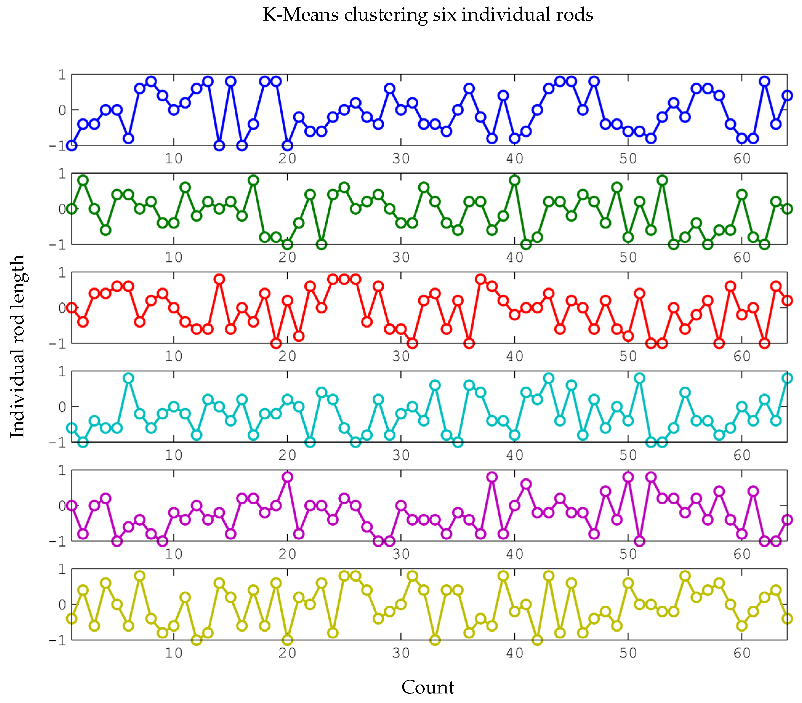
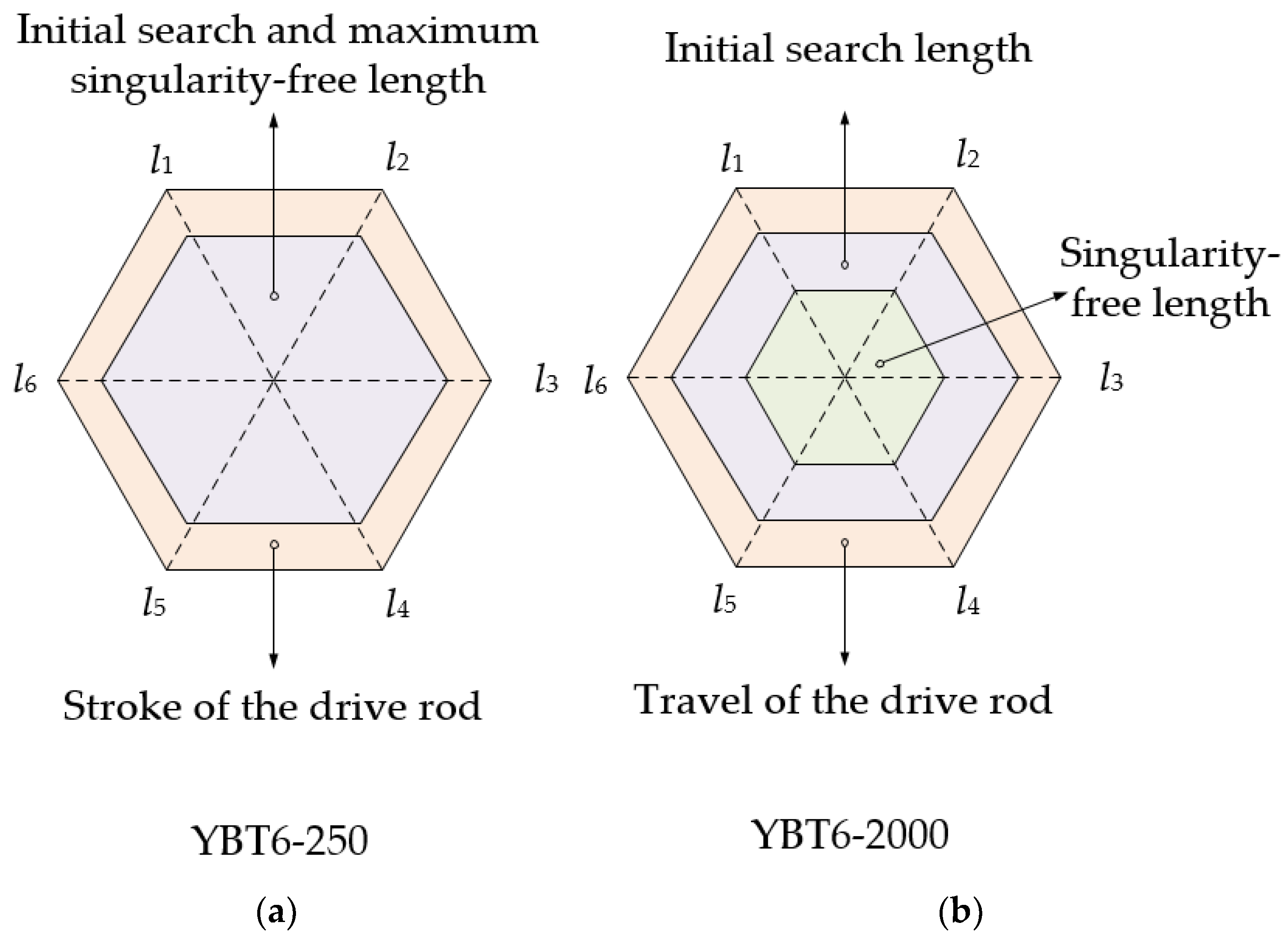
As the active joint space expands, the position and orientation range increases. Simultaneously, the singularity of the Jacobian matrix usually emerges in the extreme combinations of active joint lengths. When each rod is fully extended or fully retracted, 64 extreme combinations are obtained. Nevertheless, these 64 extreme combinations of rod lengths do not fully represent the absence of singularities within the workspace. To accurately determine if there are singular solutions in the space, appropriate combinations of rod lengths within the allowed range must be selected.
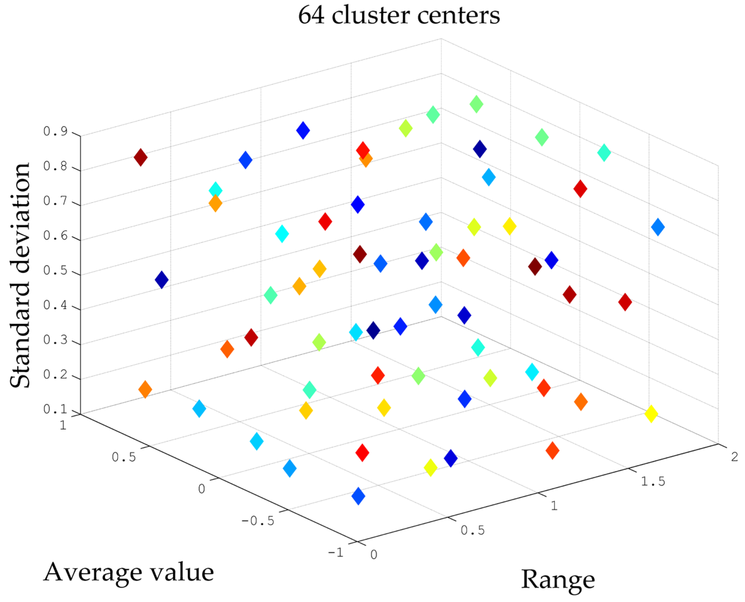
For the Stewart platform, the lengths of drive rods range from L to L . Subsequently, each rod length is normalized to the interval [−1, 1]. That normalization step ensures that the results of the 64-group clustering for each driving rod length remain invariant. Firstly, divide each rod into N equal parts, resulting in N 6 possible rod length combinations. Secondly, calculate the values of the features F 1 , F 2 , and F 3 individually. Thirdly, employ the K-Means clustering method to categorize these three features into 64 groups. Finally, based on the results of the K-Means clustering, 64 combinations of rod lengths within the range [−1, 1] can be obtained. The lengths of six drive rods are l 1 ,…, l 6 , and F 1 , F 2 and F 3 are, respectively, defined as the range, the average value, and the standard deviation of the six drive rods, as detailed below.
  • Range of six drive rods.
The range of six drive rod lengths is the difference between the maximum and minimum values, and the calculation formula is shown below.
F 1 = m a x l 1 , l 2 , l 3 , l 4 , l 5 , l 6 m i n ( l 1 , l 2 , l 3 , l 4 , l 5 , l 6 )
  • Average value of six drive rods.
The average of the six drive rod lengths is
F 2 = i = 1 6 l i 6
  • Standard deviation of six driving rods.
The standard deviation of the six drive rod lengths is
F 3 = i = 1 6 ( l i F 2 ) 2 6
The centroids of K-Means clustering are shown in Figure 3. Specifically, these centroids are differentiated by distinct colors.
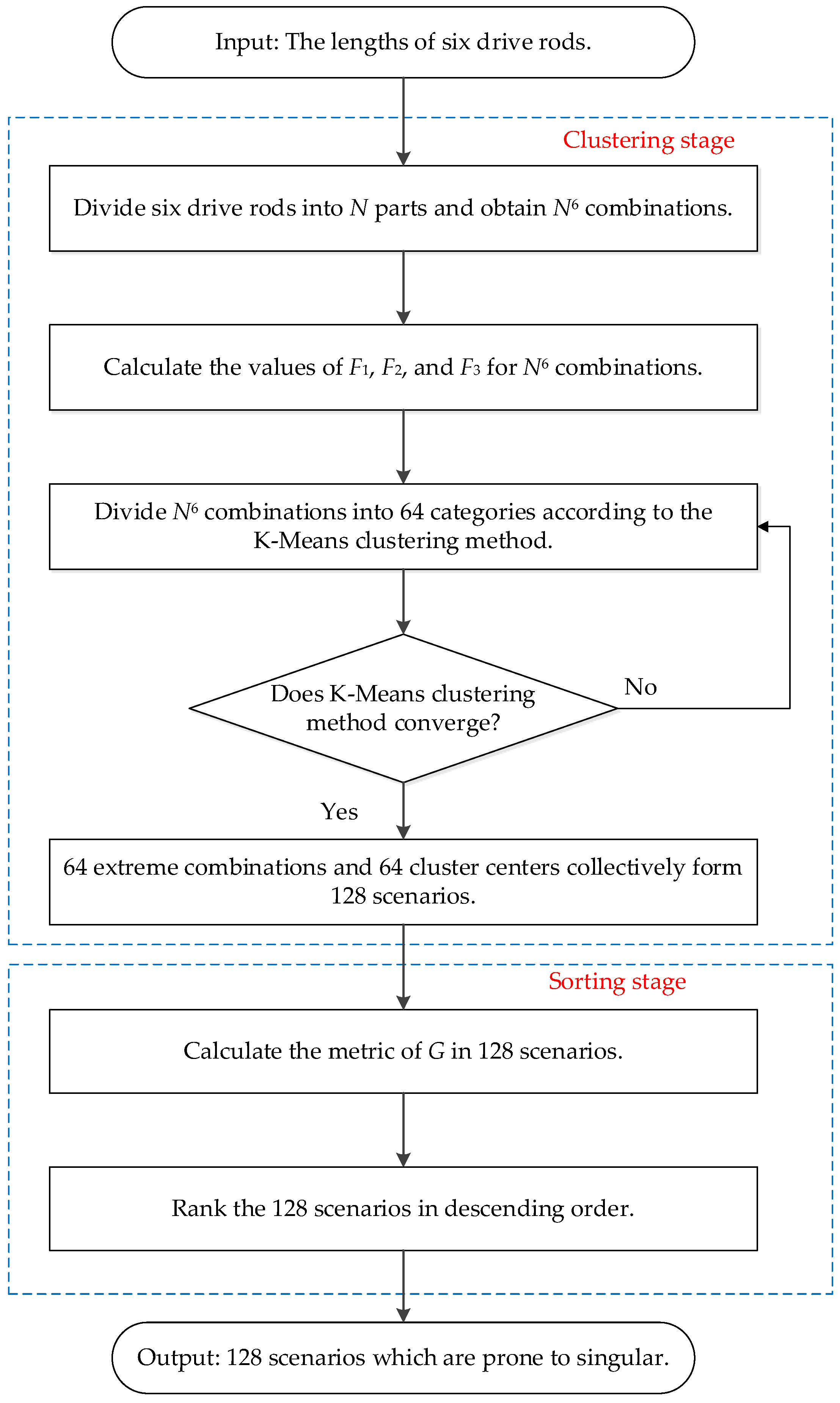
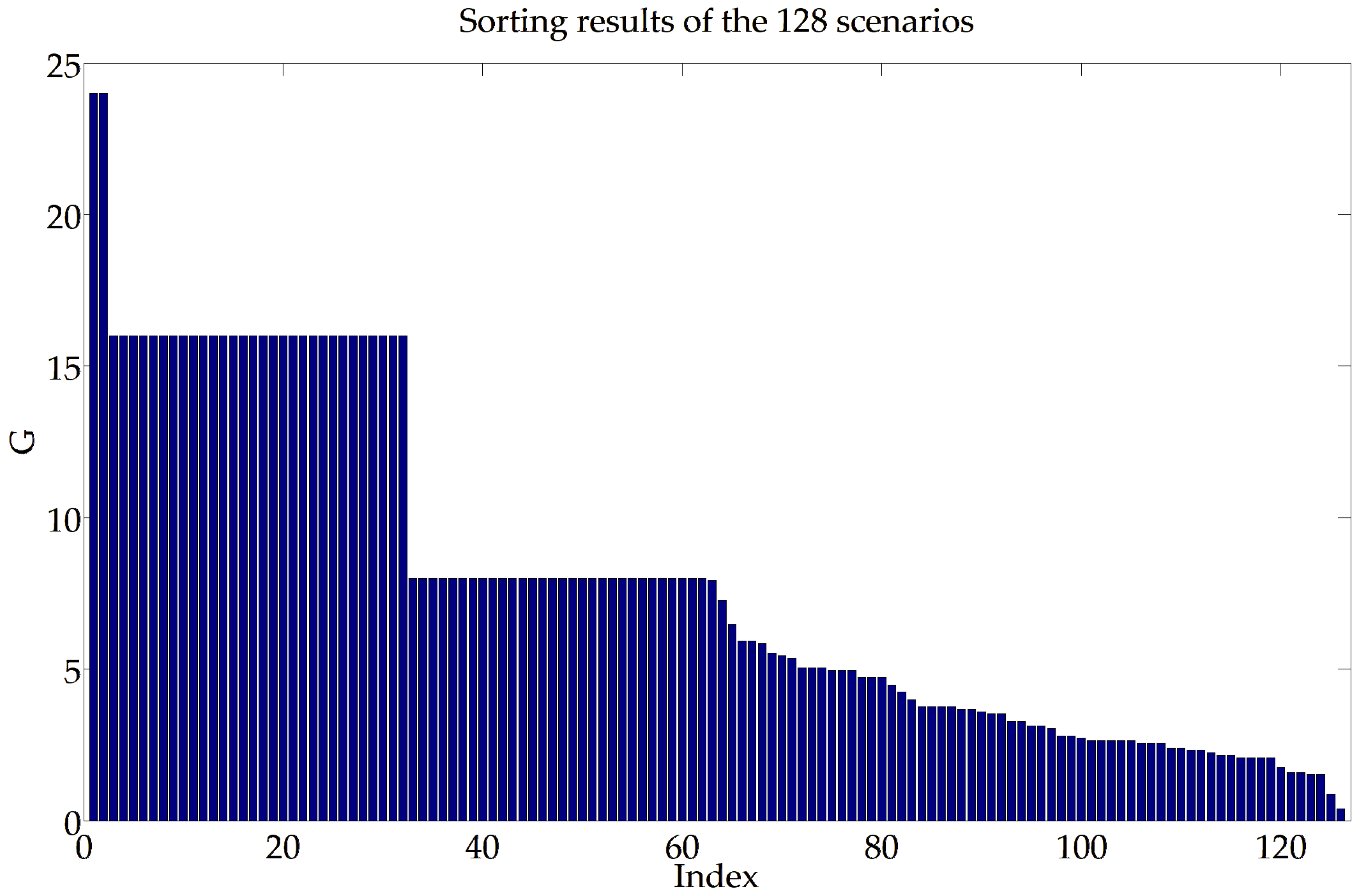
The 64 extreme combinations and 64 cluster centers collectively form 128 scenarios, which are ranked based on the metric G .
  • Circular sum of squared differences.
The circular sum of squared differences in the six drive rod lengths is
G = ( l 1 l 2 ) 2 + ( l 2 l 3 ) 2 + ( l 3 l 4 ) 2 + ( l 4 l 5 ) 2 + ( l 5 l 6 ) 2 + ( l 6 l 1 ) 2
In the clustering stage, each of the six driving rods is divided into N parts, and different categories are acquired in accordance with the K-Means clustering method. The extreme combinations and cluster centers jointly constitute the whole scenarios. In the sorting stage, all the scenarios are ranked based on the metric of G .
Typically, the Stewart platform has six DOFs in total for rotation and translation. The time complexity of the previous discretization methods is O ( N k ) , where k is the dimension of position or orientation, and there is a trade-off between accuracy and efficiency. After applying the extreme link–length combinations and the K-Means method, the time complexity is reduced to O ( N ), without sacrificing the diversity of the combinations.
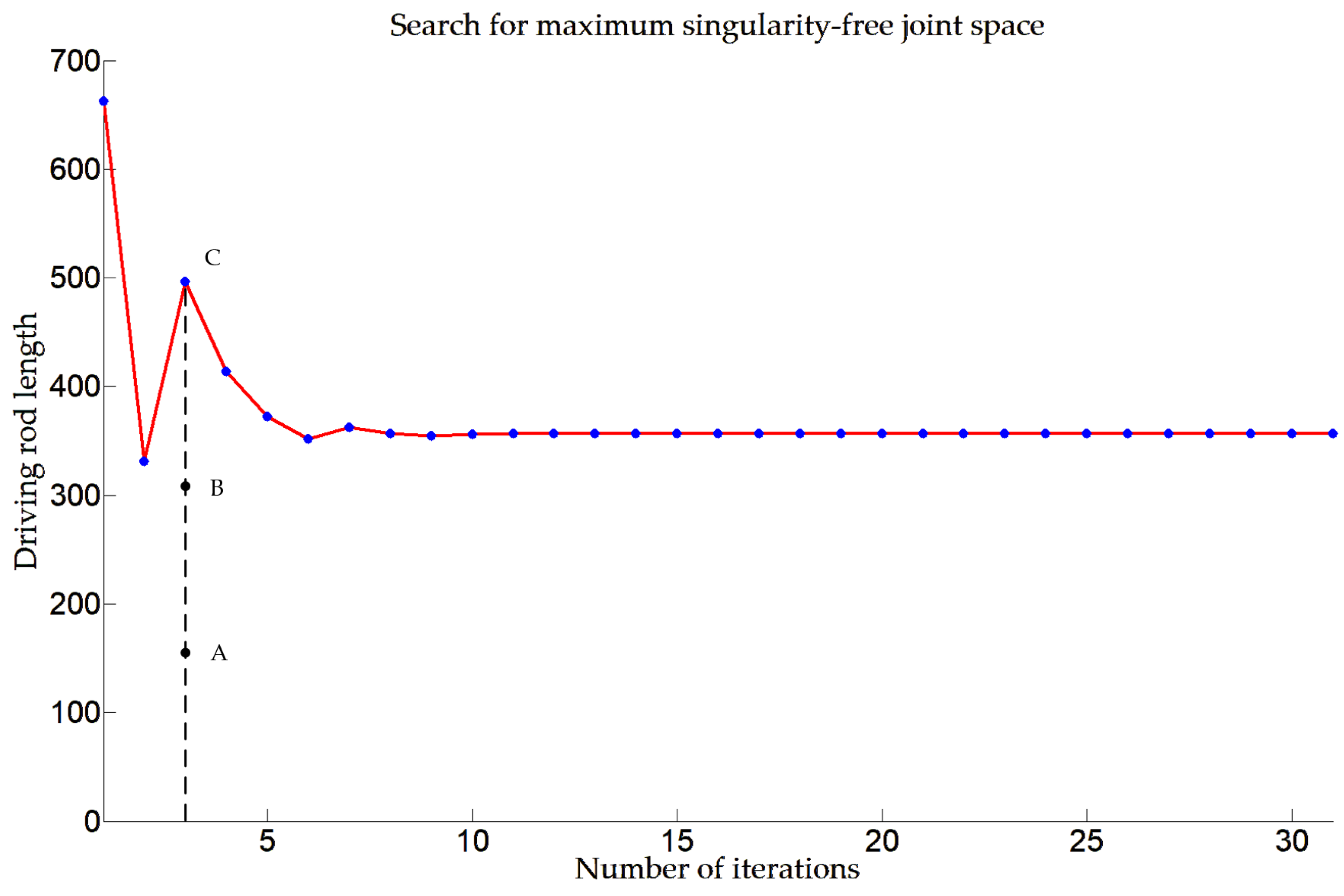
The results in Figure 4 are used to determine whether the forward kinematics is singular under the given set of rod lengths, thereby assisting in finding the maximum singularity-free joint space. By calculating the 128 scenarios, the singularity of the Stewart platform at that rod length configuration can be determined. The search procedure will not stop until the difference in the lengths of the rods between two consecutive instances is less than the predefined threshold.

4.2. Obtain the Initial Search of Maximum Singularity-Free Length Without Gimbal Lock

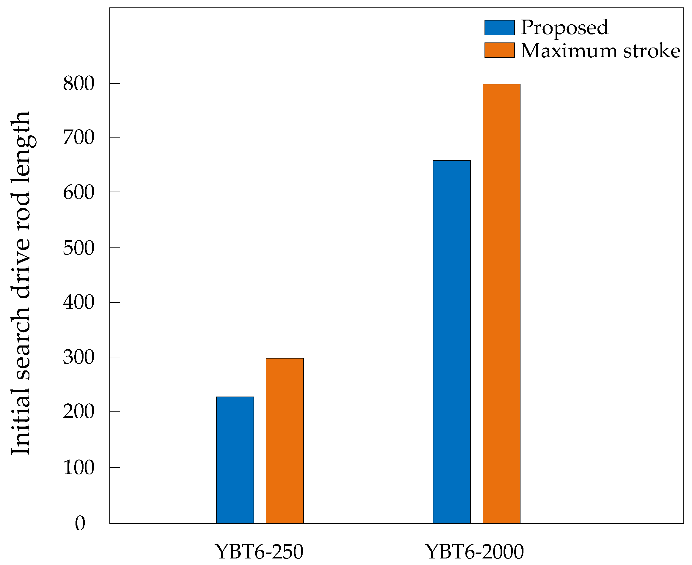
The Stewart platform experiences gimbal lock at 90°. Once any of Euler angles passes 90°, then singularities emerge, thereby leading to complex kinematic solutions and deteriorating the control accuracy and stability. Typically, the roll and pitch angles are kept below 90°. Otherwise, there is a high likelihood that the driving rod will exceed the maximum stroke. When the heading angle reaches 90°, the analytical approaches for vertical positioning must guarantee that the maximum singularity-free length of the driving rod stays within a defined range relative to the median length.
When γ = 90°, α = 0°, β = 0°, and x = 0 mm, y = 0 mm, the maximum and minimum lengths of the driving rods L max and L m i n are symmetrically distributed symmetrically on either side of the length of the driving rod at the neutral position of the Stewart platform. z is the displacement of the center of the moving platform along the Z-axis.
L max 2 = R b cos θ b 2 R a sin θ a 2 π 3 2 + R a cos θ a 2 π 3 R b s i n θ b 2 2 + ( d + z ) 2 L m in 2 = R b cos θ b 2 + R a sin θ a 2 π 3 2 + R a cos θ a 2 π 3 + R b s i n θ b 2 2 + d + z 2
Hence, the following formula is obtained, where Δ L is the maximum singularity-free active joint value:
Δ L = L max L 0 = L 0 L min L max + L min = 2 L 0 L max L min = 2 Δ L
In Equation (15), the value of Δ L can be obtained.
Δ L = L max 2 L m i n 2 4 L 0
In Equation (16), δ represents a minute constant, such as 1 × 10⁻⁹, and   Δ L is.
Δ L = Δ L δ
The analytical value obtained from Equation (16) acts as the initial value for the search for the maximum singularity-free active joint and is then resolved by means of the binary method. That scheme has the advantages of swift computation and precise solutions.

4.3. Jacobian Matrix Homogenization with Scaling Factor

Laryushkin et al. [31] separate linear and angular parameters not only for the Stewart platform but for a general parallel robot. Nevertheless, in this work, it is first assumed that the elongation and shortening lengths of each active joint are symmetrically distributed on both sides of the median rod length. After obtaining the maximum singularity-free active joint space using the content in Section 4.3 and Section 4.4, the position and orientation in the maximum singularity-free workspace are also obtained simultaneously.
The motion of the Stewart platform includes both rotational and translational motion, so the units in the traditional Jacobian matrix are not homogeneous [32]. To address that issue, constructing a dimensionless Jacobian matrix is essential for velocity mapping, singularity avoidance, accuracy and calibration, and dynamic performance. Although devoid of physical significance, that matrix aids in identifying singularities since the determinant becomes insensitive to the robot’s scale [33]. Many scholars use various methods to solve the problem of dimensional inconsistency, and these methods can be broadly classified into two main categories, namely dimensional scaling methods [34,35,36] and matrix separation techniques [37].
The position and orientation of the moving platform are represented by the vector x, and the variables of all active joints are represented by the vector θ . The kinematic closed-loop equation is shown below.
E ( θ , x ) = 0
Calculating the derivative of Equation (17) yields
E θ θ ˙ + E x x ˙ = J θ θ ˙ + J x x ˙ = 0
When representing the Jacobian matrix using dual quaternions, the sizes of Jacobian matrix J θ and J x are 8 × 8. J θ is divided into J θ ζ and J θ h , both of which have the size 8 × 4. J x is divided into two parts, the real part J x ζ and the dual part J x h , both of which have the size 8 × 4.
J θ = [ J θ ζ ,   J θ h ] J x = [ J x ζ ,   J x h ]
In this chapter, the criterion for selecting the scaling factor k satisfies Equation (20) in the initial assembly configuration and consequently applies to diverse positions and orientations within the workspace. The normalization factor used in the Jacobian matrix can reduce the condition number of the Jacobian matrix, thereby enhancing the stability of the Jacobian matrix.
k = t r ( J x ζ J x ζ T ) t r ( J x h J x h T )
Due to the inconsistency between the position and orientation dimensions, the following equation is derived.
J θ k = [ J θ ζ k , J θ h ] J x k = [ J x ζ k , J x h ]
Thus, Equation (22) is obtained according to Equations (18) and (21).
J θ k θ ˙ + J x k x ˙ = 0
Therefore, a practical approach of computing a singularity-free joint space and workspace involves detecting singularities by computing the determinant of the Jacobian matrix J x k 
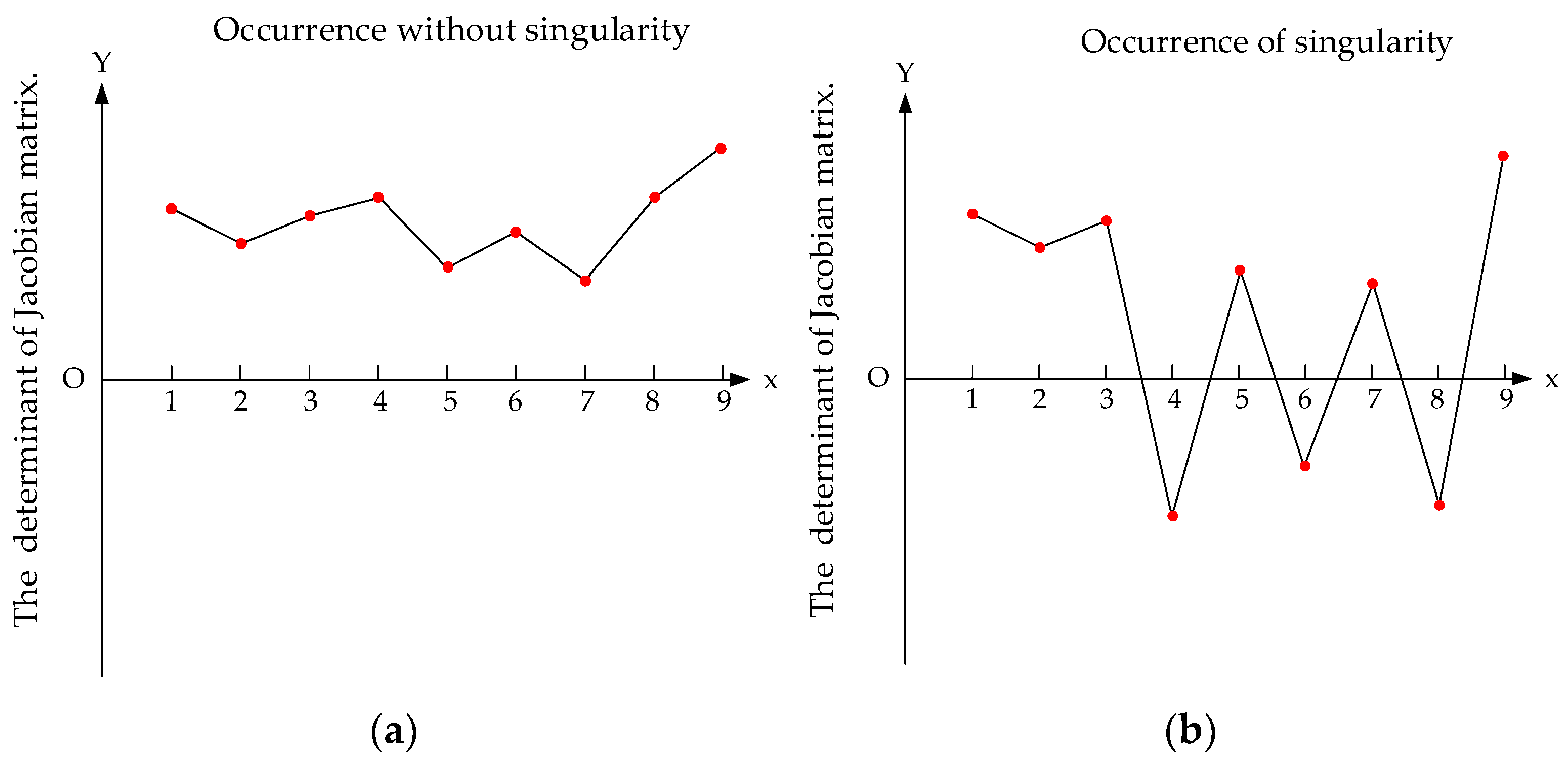
. The singularity-free workspace in this chapter is straightforward, as the fact that whether the workspace touches the singularity can be verified according to Equation (23).
det ( J x 0 k ) det ( J x k )     0
J x 0 k is the Jacobian matrix in the initial assembly configuration of the Stewart platform, and J x k is in a different position and orientation. During the computation procedure, continuously monitor the sign of the determinant of the matrix. When a change in the sign of the determinant is observed, the scenario is classified as singular. Conversely, if the sign remains unchanged, the scenario is regarded as singularity-free. The schematic diagram is shown in Figure 5.

4.4. Re-Solve Singularity-Free Space with CNN-LSTM-Attention Model

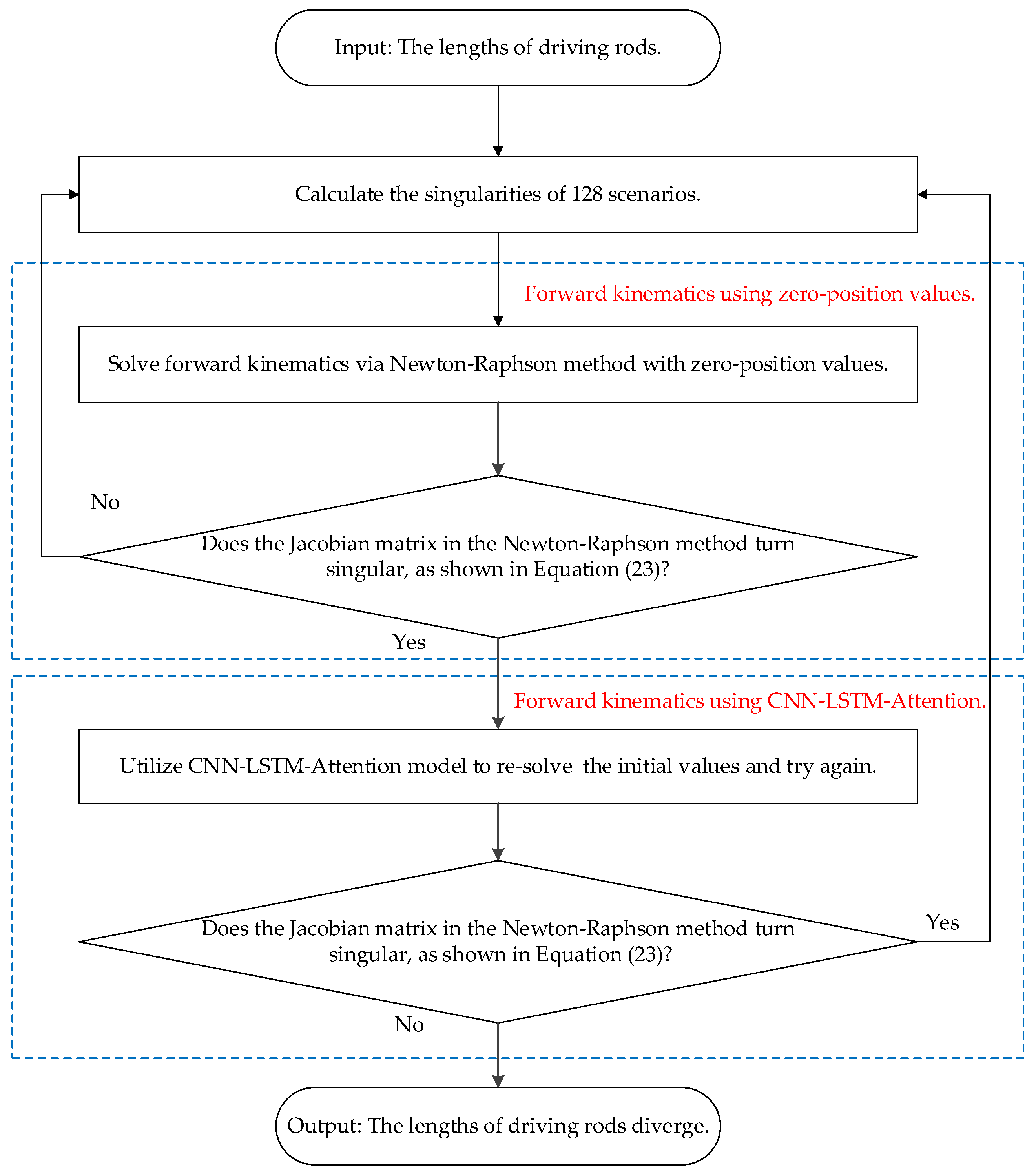
For each distinct active joint length, the forward kinematics of the 128 scenarios are computed by the Newton–Raphson method with zero-position values. When the Jacobian matrix in the Newton–Raphson method turns singular under zero-position values, causing the iteration to diverge, the CNN-LSTM-Attention model is employed to re-solve the problem using approximated values. In that case, the determinant of the Jacobian matrix is checked again for singularity, allowing for a more reliable determination of the maximum singularity-free active joint space and workspace.
When solving the forward kinematics problem of the Stewart platform, the Newton–Raphson method is superior to the homotopy continuation method, the geometric method, and other methods. The Newton–Raphson method offers a higher convergence rate. Specifically, the convergence rate is quadratic when the initial guess is from the CNN-LSTM-Attention model. The Newton–Raphson method also has lower computational complexity because it simply involves dealing with derivatives and function values. Moreover, the Newton–Raphson method is easier to implement and understand, as it is based on the intuitive Taylor expansion principle with a well-established theoretical and practical basis in relevant fields.
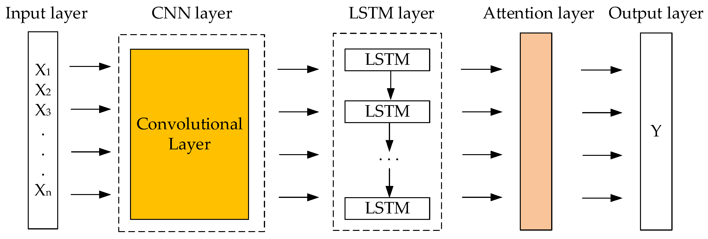
The CNN-LSTM-Attention model comprises three main components. The first component is CNN, which processes grid-structured data such as time series. The convolutional kernels of CNN slide over the data to extract features, functioning as filters for local patterns. The second component is LSTM, a specialized form of RNN meticulously designed for sequential data processing. In contrast to traditional RNNs, which encounter gradient-related challenges when dealing with long sequences, LSTM’s cell architecture adeptly mitigates these issues. LSTM can selectively govern and modulate information, thus exhibiting extraordinary proficiency in handling long-term dependencies. The third component is the Attention mechanism, which assigns weights to different input parts, enabling the model to concentrate on relevant information. By integrating the Attention mechanism with CNN and LSTM, the model’s ability to focus on crucial features within sequences or spatially structured data is significantly enhanced, thereby improving the precision-related performance.
The schematic diagram of the CNN-LSTM-Attention model is shown in Figure 6, and different colors represent different modules.
Figure 7 shows the procedure of re-solving forward kinematics with the CNN-LSTM-Attention model. In the initial stage, the forward kinematics is calculated with zero-position values. When the Jacobian matrix in the Newton–Raphson method turns singular, the CNN-LSTM-Attention model is applied for a second verification, ensuring the reliability and accuracy of the results.

5. Experiments

Offline calculation is conducted on a computer equipped with an i9-13980HX processor, boasting a maximum turbo boost frequency of 5.6 GHz, and featuring 32 GB of RAM. The software platform utilized is MATLAB 2014a.
This paper presents the validation of YBT6-250 and YBT6-2000 devices, backed by two persuasive examples.

5.1. Experimental Design and Condition

  • YBT6-250 platform
The experimental Stewart platform (YBT6-250) is shown in Figure 8. For YBT6-250, R a = 565.413 mm, R b = 747.69 mm, θ a = 16.268°, θ b = 13.056°, d = 1224.18 mm, and the stroke of the driving rod is ±300 mm.
Table 2 shows the coordinates of joint points of the moving and fixed platforms in YBT6-250.
  • YBT6-2000 platform
Another experimental Stewart platform (YBT6-2000) is shown in Figure 9. For YBT6-2000, R a = 1044.797 mm, R b = 1544.386 mm, θ a = 11°, θ b = 13°, d = 1399.764 mm, and the stroke of the driving rod is ±800 mm.
The coordinates of joint points in moving and fixed platforms of YBT6-2000 are shown in Table 3.

5.2. Experimental Results and Analysis

The scaling factors for the homogenization of the Jacobian matrix in YBT6-250 and YBT6-2000 are presented in Table 4, where the values are 1280.25 and 2559.01, respectively.
Each rod length is normalized to [−1, 1], and Figure 10 shows the results of K-Means clustering based on F 1 , F 2 , and F 3 . When the K-Means clustering algorithm is employed to solve the clustering centers, each driving rod length is normalized to the range between −1 and 1, which ensures that the results of 64-group clustering for each driving rod length remain unchanged. The figure below presents the results of the K-Means clustering. In Figure 10, different-colored lines represent distinct driving rods, and differently-colored dots denote various sample points from the K-Means clustering results.
Figure 11 illustrates the descending sorting results of the 128 scenarios in accordance with indicator G .
The preliminary search outcomes regarding the maximum singularity-free length for the drive rod lengths of YBT6-250 and YBT6-2000 are illustrated in Figure 12.
Table 5 shows the initial search drive rod length of YBT6-250 and YBT6-2000. The maximum stroke is 300 mm and 800 mm, and the initial search of singularity-free length without gimbal lock is 225.18 mm and 662.44 mm. In addition, the final singularity-free length is 225.18 mm and 356.49 mm in YBT6-250 and YBT6-2000.
Figure 13 presents the search outcomes of drive rod lengths in YBT6-250 and YBT6-2000. The yellow region represents the travel of the drive rod, and the purple and green regions denote the initial search length and singularity-free length, respectively.
As YBT6-250 encountered the issue of gimbal lock, the CNN-LSTM-Attention model is applied in YBT6-2000.
Figure 14 shows the search procedure for maximum singularity-free joint space. During the first iteration, the Jacobian matrix in the Newton–Raphson method becomes singular, leading to the divergence in solving forward kinematics. Points A, B, and C serve as trisection points, and their positions and orientations are calculated. Consequently, the CNN-LSTM-Attention model is employed to prevent improper initial values in Newton’s iteration method from eliciting divergence in the forward kinematics. Blue dots denote the maximum singularity-free lengths in each iterative search. The red line is the connecting trajectory, and the black dashed line indicates the search process within one iteration.
Table 6 shows the application of the CNN-LSTM-Attention model. Using the values of point C, the position and orientation is α = 45°, β = 7°, γ = 6°, x = 42 mm, y = 39 mm, z = −15 mm, and those values are able to obtain a more trustworthy maximum singularity-free joint space.
Figure 15 shows the maximum workspace of YBT6-250. The left figure below is position boundary, and the right figure is orientation boundary.
Table 7 shows the maximum singularity-free position and orientation boundary of YBT6-250.
Figure 16 shows the position and orientation boundary of YBT6-2000. The left figure below is position boundary, and the right figure is orientation boundary.
Table 8 shows the maximum singularity-free position and orientation boundary of YBT6-2000.
Once the maximum singularity-free joint space is obtained, the actual workspace can then be derived. When any position or orientation reaches the maximum value, the length within the actual workspace must be kept below the length of the maximum singularity-free joint space. That can serve as a design constraint or a motion constraint for the Stewart platform. Figure 17 and Figure 18 illustrate the actual and maximum singularity-free workspaces for YBT6-250 and YBT6-2000.

5.3. Comparison of Computational Efficiency and Accuracy

  • YBT6-250 platform
In accordance with the DM-DQ method presented in Ref. [30], this paper categorizes each driving rod length into three distinct scenarios: L , 0, and L . Therefore, there are 729 combinations of driving rod lengths.
Table 9 presents a comparison of the computational efficiencies of three methods, and each algorithm ceases the operation after a certain number of iterations. Apparently, in contrast to the DM-DQ and the evolutionary strategy, the proposed method demonstrates the lowest number of iterations and the shortest calculation time. Specifically, the calculation time has been significantly reduced by 97.54% and 98.07%, respectively.
The maximum deviation represents the difference between the computed value and the accurate value. As shown in Table 10, the proposed method evidently achieves the highest level of accuracy when compared with DM-DQ and the evolutionary strategy. The precision of the method expounded herein has been significantly enhanced, and the precision has been improved by 95.83% and 99.99%, respectively, compared with DM-DQ and the evolutionary strategy.
  • YBT6-2000 platform
Table 11 presents a comparison of computational efficiency of three methods in YBT6-2000, and each algorithm ceases the operation after a certain number of iterations. Apparently, the proposed method demonstrates the lowest number of iterations and the most abbreviated calculation time, thereby enhancing the computational efficiency significantly. The calculation time has been significantly reduced by 80.84% and 81.80%, respectively.
Table 12 illustrates that the proposed method attains a high level of accuracy, surpassing the other methods in terms of precision. Precisely, the precision of the method expounded herein has been significantly enhanced, and the precision has been improved by 78% and 99.99%, respectively, compared with DM-DQ and the evolutionary strategy.

6. Conclusions

To overcome the deficiencies of computational efficiency, precision, and reliability in the existing methods, this work proposes an efficient and high-precision method of calculating maximum singularity-free space in the Stewart platform based on K-Means clustering and the CNN-LSTM-Attention model. Firstly, employ the K-Means clustering and sorting method, which could improve computational efficiency during each iteration and ensure that the leading rod length combinations were more likely to converge to singularity, thereby facilitating earlier termination of the iteration and further enhancing the efficiency. Secondly, the proposed initial search aims to determine the maximum singularity-free length while avoiding gimbal lock. When gimbal lock occurs, the loss of DOFs may cause the determinant value to be zero or approach zero. The proposed method effectively reduces the search scope within the singularity-free joint space. Thirdly, the Jacobian matrix of the Stewart platform, represented in the form of dual quaternions, encompasses parameters related to both position and orientation that possess distinct dimensionalities. To address that issue, a novel dimension-scaling factor is introduced, effectively mitigating the dimensional discrepancy problem. Consequently, the newly constructed Jacobian matrix is employed to determine whether the forward kinematics associated with various sets of driving rod-length combinations are singular. Finally, a CNN-LSTM-Attention model is deployed to approximate the final result of the Newton–Raphson method, particularly when dealing with singularities in forward kinematics through the utilization of inappropriate zero-position values.
Compared with the previous algorithms for solving the singularity-free workspace, the proposed method has the following advantages. (1) The method employs the K-Means clustering and sorting approach, which not only enhances computational efficiency but also ensures the diversity of rod length combinations. Consequently, when compared with traditional discrete methods, the time complexity has been reduced to O ( M N ), where M and N are the numbers of iterations and discrete segments, respectively. (2) The method develops an approach to initially determine the maximum singularity-free length while avoiding gimbal lock. Meanwhile, that approach reduces the searching range of the maximum singularity-free driving rod lengths, rather than searching from the driving rods’ maximum stroke. (3) The method proposes a novel scaling factor to address the issue of inconsistent dimensionalities between rotational and translational elements in the Jacobian matrix, and the newly constructed Jacobian matrix is utilized to determine singularity. (4) The proposed method utilizes a CNN-LSTM-Attention model to perform a secondary verification of the Newton–Raphson method applied in forward kinematics. When the Jacobian matrix within the Newton–Raphson turns singular under zero-position values, such verification serves to enhance the reliability of the results.
The experiments show that the proposed accelerated calculation method for the maximum singularity-free joint space and workspace of the Stewart platform is applicable to devices with diverse geometric configurations. For the two practical platforms, the computation time has been reduced by 97.54% and 80.84%, respectively, in contrast to DM-DQ and the evolutionary strategy, and the precision has been improved by 95.83% and 99.99%, respectively. Moreover, the computation time has been reduced by 98.07% and 81.80% compared with the evolutionary strategy, and the precision has been improved by 78% and 99.99%, respectively. The results disclose that the proposed method possesses advantages over DM-DQ and the evolutionary strategy.

Author Contributions

Conceptualization, J.T.; methodology, J.T.; software, J.T.; validation, J.T.; formal analysis, J.T.; investigation, W.F.; resources, J.T.; data curation, J.T.; writing—original draft preparation, J.T.; writing—review and editing, W.F.; visualization, J.T.; supervision, W.F.; project administration, H.Z. All authors have read and agreed to the published version of the manuscript.

Funding

This research was funded by Research on Key Technologies of High-Performance CNC System Product Package (2023BAA010-1).

Institutional Review Board Statement

Not applicable.

Informed Consent Statement

Not applicable.

Data Availability Statement

Data are contained within the article.

Conflicts of Interest

The authors declare no conflicts of interest.

References

  1. Jiang, Q.; Gosselin, C.M. The maximal singularity-free workspace of the Gough–Stewart platform for a given orientation. J. Mech. Des. 2008, 130, 112304. [Google Scholar] [CrossRef]
  2. Jiang, Q.; Gosselin, C.M. Determination of the maximal singularity-free orientation workspace for the Gough–Stewart platform. Mech. Mach. Theory 2009, 44, 1281–1293. [Google Scholar] [CrossRef]
  3. Tsai, K.Y.; Lo, I.T.; Lin, P.J. Compatible reachable workspaces of symmetrical Stewart–Gough parallel manipulators. Mech. Mach. Theory 2014, 77, 111–121. [Google Scholar] [CrossRef]
  4. Jiang, Q.; Gosselin, C.M. Maximal singularity-free total orientation workspace of the Gough–Stewart platform. J. Mechan. Rob. 2009, 1, 034501. [Google Scholar] [CrossRef]
  5. Gosselin, C. Determination of the workspace of 6-DOF parallel manipulators. J. Mech. Des. 1990, 112, 331–336. [Google Scholar] [CrossRef]
  6. Jiang, Q.; Gosselin, C.M.; Wang, Y.; Fang, C. Maximal singularity-free orientation workspace over a position region of Gough–Stewart platform. Adv. Rob. 2015, 29, 1427–1436. [Google Scholar] [CrossRef]
  7. Jiang, Q.; Gosselin, C.M. Evaluation and representation of the theoretical orientation workspace of the Gough–Stewart platform. J. Mechan. Rob. 2009, 1, 021004. [Google Scholar] [CrossRef]
  8. Li, H.; Gosselin, C.M.; Richard, M.J. Determination of the maximal singularity-free zones in the six-dimensional workspace of the general Gough–Stewart platform. Mech. Mach. Theory 2007, 42, 497–511. [Google Scholar] [CrossRef]
  9. Pernkopf, F.; Husty, M.L. Workspace analysis of stewart-gough-type parallel manipulators. Proc. Inst. Mech. Eng. Part C J. Mech. Eng. Sci. 2006, 220, 1019–1032. [Google Scholar] [CrossRef]
  10. Khoshnoodi, H.; Rahmani, H.A.; Talebi, H.A. Kinematics, singularity study and optimization of an innovative spherical parallel manipulator with large workspace. J. Intell. Robot. Syst. 2018, 92, 309–321. [Google Scholar] [CrossRef]
  11. Li, B.; Wang, K.; Han, Y.; Cao, Y.; Yang, H.; Liu, S. Singularity property and singularity-free path planning of the Gough-Stewart parallel mechanism. Int. J. Adv. Robot. Syst. 2017, 14, 1729881417734971. [Google Scholar] [CrossRef]
  12. Li, S.; Chen, D.; Wang, J. An optimal singularity-free motion planning method for a 6-DOF parallel manipulator. Ind. Rob. 2020, 48, 290–299. [Google Scholar] [CrossRef]
  13. Simas, H.; Di Gregorio, R.; Simoni, R. Instantaneous Kinematics and Free-from-Singularity Workspace of 3-XXRRU Parallel Manipulators. Robotics 2023, 12, 138. [Google Scholar] [CrossRef]
  14. De, O.A.; De, P.E.; Moreno, U.; Martins, D. A new approach to singularity-free inverse kinematics using dual-quaternionic error chains in the Davies method. Robotica 2016, 34, 942–956. [Google Scholar]
  15. Nag, A.; Reddy, V.; Agarwal, S.; Bandyopadhyay, S. Identifying singularity-free spheres in the position workspace of semi-regular Stewart platform manipulators. Springer Proc. Adv. Robot. 2018, 4, 421–430. [Google Scholar]
  16. Xiang, Y.; Li, Q.; Jiang, X. Dynamic rotational trajectory planning of a cable-driven parallel robot for passing through singular orientations. Mech. Mach. Theory 2021, 158, 104223. [Google Scholar] [CrossRef]
  17. Zheng, C.; Zou, L.; Zheng, Z.; Xue, X. Kinematics modeling and singularity analysis of a 6-DOF all-metal vibration isolator based on dual quaternions. Symmetry 2023, 15, 20738994. [Google Scholar] [CrossRef]
  18. Liu, X.; Wang, J.; Oh, K.; Kim, J. A new approach to the design of a DELTA robot with a desired workspace. J. Intell. Robot. Syst. 2004, 39, 209–225. [Google Scholar] [CrossRef]
  19. Zhang, L.; Li, Y.; Huang, Z. Analysis of the workspace and singularity of planar 2-DOF parallel manipulator with actuation redundancy. In Proceedings of the IEEE International Conference on Mechatronics and Automation, Luoyang, China, 25–28 June 2006; pp. 171–176. [Google Scholar]
  20. Merlet, J.P. Determination of the orientational workspace of parallel manipulators. J. Intell. Robot. Syst. 1995, 13, 143–160. [Google Scholar] [CrossRef]
  21. Li, W.; Angeles, J. A Novel Three-Loop Parallel Robot with Full Mobility: Kinematics, Singularity, Workspace, and Dexterity Analysis. J. Mech. Robot. 2017, 9, 051003. [Google Scholar] [CrossRef]
  22. Liu, G.; Qu, Z.; Liu, X.; Han, J. Singularity analysis and detection of 6-UCU parallel manipulator. Robot. Comput.-Integr. Manuf. 2014, 30, 172–179. [Google Scholar] [CrossRef]
  23. Merlet, J.P. A formal-numerical approach for robust in-workspace singularity detection. IEEE Trans. Rob. 2007, 23, 393–402. [Google Scholar] [CrossRef]
  24. Kaloorazi, M.H.F.; Masouleh, M.T.; Caro, S. Determining the maximal singularity-free circle or sphere of parallel mechanisms using interval analysis. Robotica 2014, 34, 135149. [Google Scholar] [CrossRef]
  25. Abbasnejad, G.; Daniali, H.M.; Kazemi, S.M. A new approach to determine the maximal singularity-free zone of 3-RPR planar parallel manipulator. Robotica 2012, 30, 10051012. [Google Scholar] [CrossRef]
  26. Nag, A.; Bandyopadhyay, S. Singularity-free spheres in the position and orientation workspaces of Stewart platform manipulators. Mech. Mach. Theory 2021, 155, 104041. [Google Scholar] [CrossRef]
  27. Wang, Z.; Ji, S.; Li, Y.; Wan, Y. A unified algorithm to determine the reachable and dexterous workspace of parallel manipulators. Inf. Control 2010, 26, 454–460. [Google Scholar] [CrossRef]
  28. Cheng, S.; Wu, H.; Wang, C. A novel method for singularity analysis of the 6-SPS parallel mechanisms. Sci. China Technol. Sci. 2011, 54, 1220–1227. [Google Scholar] [CrossRef]
  29. Ding, X. Determination of the largest collision-free and singularity-free workspaces for spatially isotropic Stewart platforms. Int. J. Adv. Manuf. Technol. 2024, 135, 5213–5234. [Google Scholar] [CrossRef]
  30. Yang, X.; Wu, H.; Chen, B.; Li, Y.; Jiang, S. A dual quaternion method in efficient determination of the singularity-free joint space and workspace of six-DOF parallel robots. Mech. Mach. Theory 2018, 129, 279–292. [Google Scholar] [CrossRef]
  31. Laryushkin, P.A.; Glazunov, V.A. On the estimation of closeness to singularity for parallel mechanisms using generalized velocities and reactions. In Proceedings of the IFToMM World Congress, Taipei, Taiwan, 25–30 October 2015; pp. 286–291. [Google Scholar]
  32. Merlet, J.P. Jacobian, Manipulability, Condition Number, and Accuracy of Parallel Robots. J. Mech. Des. 2006, 128, 199–206. [Google Scholar] [CrossRef]
  33. Li, Y.; Yang, X.L.; Wu, H.T.; Chen, B. Optimal design of a six-axis vibration isolator via Stewart platform by using homogeneous Jacobian matrix formulation based on dual quaternions. J. Mech. Sci. Technol. 2018, 32, 11–19. [Google Scholar] [CrossRef]
  34. Khan, S.; Andersson, K.; Wikander, J. Jacobian matrix homogenization-A comparison of different approaches in the context of multi-objective optimization of 6-DOF haptic devices. J. Intell. Robot. Syst. Theory Appl. 2015, 79, 87–100. [Google Scholar] [CrossRef]
  35. Ma, O.; Angeles, J. Optimum architecture design of platform manipulators. In Proceedings of the Fifth International Conference on Advanced Robotics Robots in Unstructured Environments, Pisa, Italy, 19–22 June 1991; pp. 1130–1135. [Google Scholar]
  36. Kim, S.G.; Ryu, J. New Dimensionally Homogeneous Jacobian Matrix Formulation by Three End-Effector Points for Optimal Design of Parallel Manipulators. IEEE Trans. Robot. Autom. 2003, 19, 731–736. [Google Scholar]
  37. Cardou, P.; Bouchard, S.; Gosselin, C. Kinematic-sensitivity indices for dimensionally nonhomogeneous Jacobian matrices, Robotics. IEEE Trans. Robot. 2010, 26, 166–173. [Google Scholar] [CrossRef]
Figure 1. The overview of the proposed method.
Actuators 14 00074 g001
Figure 2. The spatial position relationship of joint points in the Stewart platform.
Actuators 14 00074 g002
Figure 3. The centroids of K-Means clustering.
Actuators 14 00074 g003
Figure 4. The flowchart of K-Means clustering followed by sorting.
Actuators 14 00074 g004
Figure 5. The determinant of J x k . (a) Occurrence without singularity; (b) occurrence with singularity.
Actuators 14 00074 g005
Figure 6. The schematic diagram of CNN-LSTM-Attention model.
Actuators 14 00074 g006
Figure 7. Procedure of calculating the maximum singularity-free space on the Stewart platform.
Actuators 14 00074 g007
Figure 8. The experimental Stewart platform YBT6-250.
Actuators 14 00074 g008
Figure 9. The experimental Stewart platform YBT6-2000.
Actuators 14 00074 g009
Figure 10. The results of K-Means clustering based on F 1 , F 2 , and F 3 .
Actuators 14 00074 g010
Figure 11. The descending sorting results of the 128 scenarios.
Actuators 14 00074 g011
Figure 12. Initial search of maximum singularity-free length.
Actuators 14 00074 g012
Figure 13. The search results of drive rod lengths. (a) YBT6-250; (b) YBT6-2000.
Actuators 14 00074 g013
Figure 14. The search procedure for maximum singularity-free joint space.
Actuators 14 00074 g014
Figure 15. The workspace of YBT6-250. (a) Position boundary; (b) orientation boundary.
Actuators 14 00074 g015
Figure 16. The workspace of YBT6-2000. (a) Position boundary; (b) orientation boundary.
Actuators 14 00074 g016
Figure 17. The actual workspace and maximum singularity space of YBT6-250.
Actuators 14 00074 g017
Figure 18. The actual workspace and maximum singularity space of YBT6-2000.
Actuators 14 00074 g018
Table 1. Comparison among the existing algorithms for computing singularity-free space.
MethodsTime ComplexityApplicable to Any Geometric ConfigurationInitial Value OptimizationSimultaneous Consideration of Position and Orientation
Geometrical methods
[18,19,20,21] O ( 1 ) NoNo
Numerical methods
[22] O ( M 1 N 1 K 1 ) YesNoYes
[23] O ( N 6 ) YesNoYes
[24] O ( N 3 ) NoNoNo
[25] O ( M 2 N 2 K 2 ) YesNoYes
[26] O ( N 3 ) NoNoNo
Discretization methods
[27] O ( N 3 ) YesNoNo
[28] O ( N 3 ) YesNoNo
[29] O ( N 3 ) YesNoNo
[30] O ( M N 6 ) YesNoYes
Proposed O ( M N ) YesYesYes
Table 2. Joint point coordinates of moving and fixed platforms in YBT6-250 (units: mm).
Chain 1Chain 2Chain 3Chain 4Chain 5Chain 6
X a −444.74444.74524.7480.00−80.00−524.74
Y a 349.14349.14210.58−559.72−559.72210.58
Z a 000000
X b −85.0085.00685.82600.82−600.82−685.82
Y b 742.84742.84297.81−445.04−445.04−297.81
Z b −1224.18−1224.18−1224.18−1224.18−1224.18−1224.18
Table 3. Joint point coordinates of moving and fixed platforms in YBT6-2000 (units: mm).
Chain 1Chain 2Chain 3Chain 4Chain 5Chain 6
X a −850.59850.59950.73100.14−100.14−950.73
Y a 606.72606.72433.27−1039.99−1039.99433.27
Z a 000000
X b −174.83174.831416.291241.47−1241.47−1416.29
Y b 1534.461534.46−615.82−918.64−918.64−615.82
Z b −1399.76−1399.76−1399.76−1399.76−1399.76−1399.76
Table 4. The scaling factor of Jacobian matrix homogenization.
YBT6-250YBT6-2000
The scaling factor k1280.252559.01
Table 5. Different drive rod length.
Maximum Stroke (mm)Initial Search Length (mm)Singularity-Free Length (mm)
YBT6-250300225.18225.18
YBT6-2000800662.44356.49
Table 6. The application of the CNN-LSTM-Attention model.
ABC
α (°)12.49 25.98 43.36
β (°)2.34 4.64 5.20
γ (°)1.08 2.86 7.66
x (mm)−0.05 9.18 31.63
y (mm)−23.04 −21.72 56.50
z (mm)12.73 15.82 −21.51
Table 7. The maximum singularity-free position and orientation boundary of YBT6-250.
MinimumMaximum
α (°)−36.8235.31
β (°)−32.3332.33
γ (°)−89.9989.99
x (mm)−734.55734.55
y (mm)−691.98713.39
z (mm)−313.69242.35
Table 8. The maximum singularity free position and orientation of YBT6-2000.
MinimumMaximum
α (°)−38.1138.91
β (°)−35.4435.44
γ (°)−32.5632.56
x (mm)−741.71741.71
y (mm)−663.54764.94
z (mm)−507.68437.90
Table 9. Comparison of computational efficiency for YBT6-250.
Proposed DM-DQEvolutionary Strategy
Number of iterations13333
Forward kinematics
per iteration
12872964
Number of forward kinematics12812,302
Total time (s)118.174797.336132.14
Table 10. Comparison of computational precision for YBT6-250.
Proposed DM-DQEvolutionary Strategy
Maximum
derivation (mm)
1 × 10−92.4 × 10−87.33 × 10⁻⁶
Table 11. Comparison of computational efficiency for YBT6-2000.
Proposed DM-DQEvolutionary Strategy
Number of iterations313232
Forward kinematics
per iteration
12872964
Number of forward kinematics244812,592
Total time (s)1243.416489.726833.25
Table 12. Comparison of computational precision for YBT6-2000.
Proposed DM-DQEvolutionary Strategy
Maximum
derivation (mm)
3.3 × 10−81.5 × 10−70.048
Disclaimer/Publisher’s Note: The statements, opinions and data contained in all publications are solely those of the individual author(s) and contributor(s) and not of MDPI and/or the editor(s). MDPI and/or the editor(s) disclaim responsibility for any injury to people or property resulting from any ideas, methods, instructions or products referred to in the content.

