Article

Path Tracking Control for Underground Articulated Vehicles with Multi-Timescale Predictive Modeling

School of Mechanical Engineering, University of Science and Technology Beijing, Beijing 100083, China
*
Author to whom correspondence should be addressed.
Actuators 2025, 14(10), 477; https://doi.org/10.3390/act14100477
Submission received: 14 August 2025 / Revised: 24 September 2025 / Accepted: 26 September 2025 / Published: 28 September 2025
(This article belongs to the Section Actuators for Surface Vehicles)

Abstract

To enhance the path-tracking accuracy and control stability of articulated underground vehicles navigating high-curvature tunnels, this paper proposes a novel Multi-Time-Scale Nonlinear Model Predictive Control (MTS-NMPC) strategy. The core innovation lies in its dynamic adaptation of the prediction horizon to simultaneously compensate for the body torsion effects and yaw deviations induced by high-speed cornering. A high-fidelity vehicle dynamics model is first established. Subsequently, an adaptive mechanism is designed to adjust the prediction horizon based on the reference speed and road curvature. Experimental results demonstrate that the proposed MTS-NMPC achieves remarkable reductions of 35% and 17% in the maximum lateral tracking error and heading deviation, respectively, compared to conventional NMPC. It also improves stability by suppressing the velocity fluctuations of the articulated joint. The superior control performance and robustness of our method are further validated through field tests in an underground mine.

1. Introduction

In the field of deep well mineral resource extraction, Articulated Vehicle (AV) has become a key equipment to realize efficient operation due to its advantage of integrating shoveling, loading and transporting functions. Its unique articulated body structure gives it steering characteristics that are significantly different from those of rigid vehicles, showing higher flexibility and ability to adapt to complex environments. With a background in smart mine construction, promoting the intelligence and unmanned articulated vehicles has become an important direction for future development [1]. However, the complexity of deep mine tunnel environments, with large variations in road curvature and spatial constraints, puts high demands on the path tracking control of articulated vehicles [2]. Due to the special body structure, the articulated vehicle experiences more significant body posture changes during steering, resulting in poor lateral stability. During the tracking control process on complex roads, the control system frequently adjusts the steering hydraulic cylinder, causing the vehicle to “twist and sway” severely, which seriously affects the driving stability of the vehicle. Accurate and stable path tracking control is not only a key technical link to achieve unmanned articulated vehicles, but also a core issue to ensure the reliability and safety of the system under the complex operating environment [3].
Extensive research has been conducted in the domain of path tracking control for articulated vehicles, yielding significant advancements. Zhang et al. [4] employed PID and fuzzy control techniques to minimize deviations from predefined paths. Deshmukh [5] introduced an enhanced PID method incorporating slip compensation to improve path tracking performance. Cui [6] developed a control system for articulated tracked vehicles, utilizing distance and heading angle deviations as inputs to regulate hinge deflection and sprocket speed. Their approach compared fuzzy PID and conventional PID controllers, with simulations demonstrating superior performance of the fuzzy PID algorithm. Dou [7] proposed a path planning and tracking framework for autonomous mining articulated vehicles, integrating a PID controller with model predictive control (MPC) for steering. This framework utilized a relationship space method and a self-organizing competitive neural network for spatial identification and path planning, achieving effective path tracking through combined PID and MPC steering control. Huang [8] implemented an improved pure pursuit model combined with a PID controller to reduce lateral tracking errors. Chenming [9] applied the NSGA-II optimization algorithm to enhance the accuracy of pure pursuit-based path tracking control.
Given the unique demands of mining environments, where significant variations in path curvature pose substantial challenges to vehicle handling accuracy, driving stability, and safety, the study of path tracking under large curvature conditions is critical for enhancing the adaptability of specialized vehicles, such as articulated vehicles, in complex terrains. Hu [10] proposed a linear parameter-varying approach to address the highly nonlinear characteristics of an all-terrain vehicle’s kinematic tracking error model, designating an adaptive model predictive controller (AMPC) based on MPC. Compared to a fuzzy PID controller, the AMPC demonstrated faster reference path tracking and reduced errors, though its accuracy remained inferior to nonlinear model predictive control (NMPC). Sun [11] developed an integrated path tracking controller for articulated vehicles using NMPC, incorporating a terminal cost to enhance controller stability and reduce tracking errors. However, further improvements in accuracy and adaptability are still required to meet the demands of complex mining scenarios.
MENG [12] introduced the MPC method, which realized the optimal control of vehicle speed and articulation angle by optimizing the objective function of predictive control, and effectively solved the control problems of multi-variable and multi-constraint systems. At the same time, for the problem that the MPC algorithm cannot judge the tracking overshoot due to the sudden change in road curvature in advance, a control method based on the pre-scanning distance is proposed, which improves the accuracy and stability of vehicle path tracking. Zhou [13] proposed an adaptive time-domain parameter method using MPC in the path tracking control of articulated steerable tractor. The AMPC is achieved by establishing the kinematic and multi-body dynamics model of articulated steered tractor and combining the genetic algorithm to optimize the optimal time-domain parameters under real-time vehicle speed, vehicle attitude and road conditions.
With the rapid development of unmanned technology, complex path tracking control has become an important research field to improve the autonomous navigation capability of vehicles. Complex path tracking control not only requires the vehicle to be able to accurately track the preset path, but also needs to ensure the stability and safety of driving under different working conditions. The path tracking control of articulated vehicles is subject to several system constraints, including the articulation angle and the articulation angular velocity. In view of this, many researchers [14,15,16,17] have started the research based on MPC.
Due to the large capacity of articulated vehicles, their increased mass and size can lead to lateral instability problems, which can lead to safety-critical situations. Tang [18] et al. used optimal control theory to improve vehicle path tracking and also designed an adaptive pose control strategy to ensure stability. Yu [19] developed a path tracking control scheme using an LQR controller. Liu [20] et al. used MPC as a control technique to improve vehicle path tracking. MPC was used as a control technique to improve vehicle path tracking. Zhang [21] used two-layer learning MPC for vehicle yaw stability control and path tracking. To address the lateral stability and external disturbances of articulated vehicles, Lee [22] proposed a tube-based MPC for path and speed tracking of automated articulated vehicles, in which the LQR controller is combined with a Tube-based MPC. The proposed algorithm achieves minimal path tracking error and enhanced robustness against external noise compared to the basic MPC. Rahman [23] proposed two transversal controllers for this purpose: the Front Axle Reference (FAR) and the Adaptive Reference (AR). Both controllers are designed using artificial flow guidance, with the FAR focusing on precise path tracking at the front of the vehicle and the AR mimicking human driving behavior to reduce overall deviation while maintaining stability. Simulations rendered in TruckMaker show that both controllers exhibit centimeter-level path-tracking accuracy and higher lateral stability at multiple speeds, and are robust to trailer mass variations, compared to commonly used methods.
Traditional single-model and parametric controllers have difficulty in balancing tracking error and computational efficiency under multiple operating conditions, Chen [24] proposed a novel fuzzy logic switching MPC algorithm specifically applied to articulated steering vehicles to address path tracking challenges due to changes in road conditions and vehicle speed. This fuzzy MPC algorithm can effectively overcome the limitations of the single-model approach and ensure accurate, stable and efficient path tracking under different adhering road conditions, but its adaptability to different tracking demands is weak. In order to simultaneously improve the accuracy and real-time performance of articulated vehicle path tracking control based on single reference point LMPC (SRP-LMPC), Bai [25] proposed a path tracking control method based on nonlinearly compensated multiple reference point LMPC (MRP-LMPC). This scheme solves both the problem of poor real-time performance of NMPC and the problem of poor accuracy of SRP-LMPC, but there are some delays and lags in the application of complex paths. He [26] proposed a path tracking control technique based on the T-S fuzzy model of vehicle autonomy at heading angle, which is used to improve the accuracy of road tracking in the case where the vehicle is at a large side-slip angle. Particularly noteworthy is the situational altruism weight allocation mechanism proposed by Lima et al. [27], which offers a novel approach to cooperative control by dynamically elevating the priority of subsystems approaching performance thresholds. However, this mechanism fails to account for control lag caused by abrupt road curvature changes, and its weight-switching logic relies on global optimization, resulting in increased computational overhead.
Although Model Predictive Control (MPC) and Nonlinear Model Predictive Control (NMPC) have achieved considerable advances in path tracking applications, they exhibit notable limitations when applied to underground articulated vehicles. Firstly, conventional MPC/NMPC strategies often employ a fixed prediction horizon, which proves inadequate in adapting to the highly dynamic and curvature-varying conditions typical of mining tunnel environments. This results in insufficient prediction accuracy and noticeable tracking lag in sharp curves, while causing computational redundancy in straight or gently curved sections. Secondly, most existing methods fail to fully incorporate the unique dynamic characteristics of articulated vehicles, such as the nonlinearities inherent in hydraulic steering systems, constraints on articulation angle rates, and oscillatory body torsion effects. These oversights often lead to significant control input fluctuations and compromised driving smoothness. Furthermore, prevailing control frameworks lack effective coordination between path tracking precision and lateral stability, frequently improving tracking performance at the expense of robustness and operational safety.
To address these challenges, this study proposes a multi-timescale predictive modeling framework. The rationale for this approach is threefold: First, the spatiotemporal variability of underground tunnel environments demands adaptable control strategies—sharp curves require short-horizon prediction for rapid responsiveness, whereas long straight sections benefit from extended horizons for stability optimization, a dual requirement that fixed-horizon methods cannot simultaneously satisfy. Second, articulated vehicles exhibit inherently multi-rate dynamic behaviors, such as fast hydraulic actuation response versus slower vehicle posture changes, necessitating a multi-timescale structure to accurately represent these distinct dynamical processes. Third, by establishing a functional mapping among vehicle speed, path curvature, and the optimal prediction horizon, the proposed method enables dynamic adjustment of the controller’s preview capability, thereby significantly enhancing tracking accuracy and disturbance rejection while maintaining computational feasibility in real-time applications.
Consequently, investigating path tracking control for articulated vehicles under conditions of significant curvature variations in deep mine roads holds substantial theoretical significance and practical engineering value. This study proposes a multi-timescale nonlinear model predictive control method, with the following key contributions:
(1)
This study develops a comprehensive dynamic model for articulated vehicles by integrating two key components. First, a nonlinear hydraulic steering control system is established, explicitly incorporating steering resistance to more accurately capture the real system behavior. Second, a throttle–steering coupling module is constructed based on extensive real-vehicle experimental data, effectively characterizing the interaction between throttle input and steering response. The integrated model provides a more accurate representation of the complex motion characteristics of articulated vehicles, and its engineering applicability has been validated through field tests in actual mining operations.
(2)
We propose a MTS-NMPC algorithm, which represents an innovative application for articulated vehicles. This algorithm dynamically incorporates the influence of path curvature and maximum vehicle speed on the steering process, enabling adaptive adjustment of the prediction horizon to enhance path-tracking accuracy. In contrast, conventional MPC/NMPC approaches rely on a fixed prediction horizon. Systematic experiments were conducted to quantify the mapping relationship among vehicle speed, path curvature, and the optimal prediction horizon.
(3)
Real-world path-tracking experiments were carried out in the challenging environment of an underground mine at a depth of 645 m to validate the effectiveness of the proposed MTS-NMPC algorithm. The test results demonstrate that the algorithm exhibits excellent robustness and tracking accuracy under realistic operating conditions, achieving significant reductions of 35% and 17% in the maximum lateral tracking error and heading deviation, respectively, while effectively suppressing rotational speed fluctuations at the articulated joint. These findings confirm its practical engineering value for controlling articulated vehicles in complex mining scenarios.

2. Modeling and Control Framework for Articulated Vehicle Path Tracking

2.1. Articulated Vehicle Path Tracking Model

Although articulated vehicles exhibit complex multi-body dynamics, this study focuses on underground load–haul–dump (LHD) machines, which generally operate at low speeds (typically below 10 km/h) in narrow and constrained tunnel environments. Under such operating conditions, tire slip, suspension effects, and other high-frequency dynamic phenomena are negligible compared with the dominant kinematic behavior. Therefore, the articulated vehicle kinematic model, which characterizes the geometric relations among lateral deviation, heading error, and articulation angle, is sufficient for describing the motion relevant to path tracking. This modeling choice ensures computational efficiency and robustness, while preserving the essential accuracy required for real-time MTS-NMPC-based control in underground mining scenarios.
The path tracking model for an articulated vehicle is illustrated in Figure 1. The global inertial coordinate system is denoted as XOY. Let P f represent the center point of the front axle of the articulated vehicle, and P denote the nearest reference point on the predefined path to P f . The line segment P 1 P 2 represents the tangent to the reference path at point P . The transversal error e d is defined as the perpendicular distance from point P f to the tangent line P 1 P 2 . The heading error e h is defined as the angular difference between the tangent direction of P 1 P 2 and the heading angle θ f of the vehicle’s front body, measured relative to the positive direction of the X-axis. The key challenge in articulated vehicle path tracking is to enhance lateral stability while minimizing both the transversal and heading errors. The state vector of the reference path is typically defined as:
P r e f = x 0 , y 0 , θ 0 , γ 0 x i ,   y i ,   θ i ,   γ i x n , y n , θ n , γ n
where x i and y i denote the horizontal and vertical coordinates of the reference path point, respectively; θ i represents the heading angle of the front body of the articulated vehicle; and γ i is the articulation angle between the front and rear bodies.
x = x a c t x r e f y = y a c t y r e f θ f = θ a c t θ r e f γ = γ a c t γ r e f
Let x a c t , y a c t , θ a c t , γ a c t denote the actual state vector of the articulated vehicle, and x r e f , y r e f , θ r e f , γ r e f represent the corresponding reference state vector as defined previously. The tracking errors are obtained by subtracting the reference state vector from the actual state vector. Each error component is then assigned a weight to compute the total tracking error as follows:
E = 0 n w i e i = w 1 x + w 2 y + w 3 θ ~ f + w 4 γ ~
where w 1 + w 2 + w 3 + w 4 = 1.
To unify units, angular errors are converted to metric-equivalent values using vehicle-specific geometric lengths:
θ ~ f = L · θ f γ ~ = L a · γ
where L is the distance from the front axle center to the articulation point, and L a is the distance from the articulation point to the rear reference point. Physically, a heading error θ f at the front axle induces a lateral displacement along the reference path of approximately L · θ f , while an articulation angle error γ induces a lateral displacement of roughly L a · γ .

2.2. Overall Framework of the MTS-NMPC Path Tracking System

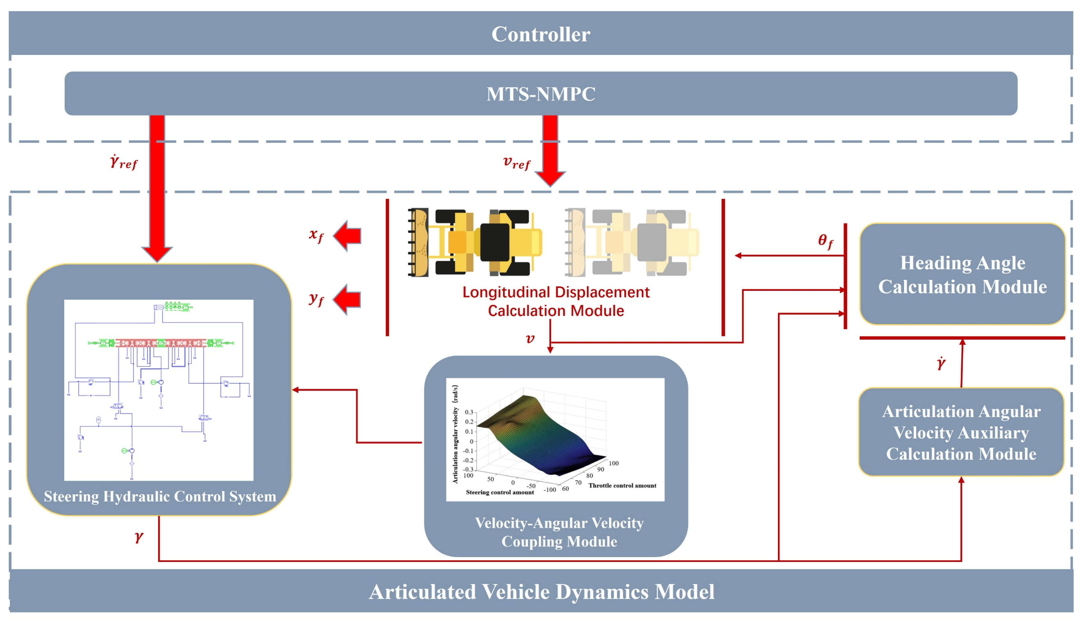
We propose a path tracking control framework for articulated vehicles based on the MTS-NMPC, as illustrated in Figure 2. This framework primarily comprises two components: the controller and the articulated vehicle dynamics model. The modeling of the vehicle dynamics is detailed in Section 3, while the design of the MTS-NMPC controller is presented in Section 4. Notably, the vehicle dynamics model was developed in a modular fashion. Initially, a model of the hydraulic steering system was established. Real-vehicle experiments subsequently revealed a coupling effect between steering and throttle operations. Therefore, in the final modeling stage, we not only incorporated the previously developed hydraulic steering system model but also introduced a coupling module to account for this interaction. As a result, a comprehensive dynamic model of the articulated vehicle was constructed.

3. Modeling of Articulated Vehicle Dynamics

This section begins with the modeling of the steering hydraulic system, including a steering resistance component to better reflect real-world behavior. It then investigates the vehicle’s dynamic response characteristics through experiments, highlighting the coupling between speed and steering. These analyses jointly lay the foundation for constructing a full-vehicle dynamics model.

3.1. Steering Resistance Analysis

This paper defines the articulation angle of an articulated vehicle as 0° when the front and rear bodies are aligned along the same axis. In this configuration, the posture of the steering mechanism is illustrated in Figure 3. Point O, located on the front body, serves as the articulation point and is taken as the origin of a right-handed Cartesian coordinate system. The x-axis is oriented horizontally to the right, from the front body toward the rear body, while the y-axis is directed upward, perpendicular to the x-axis. In state 1, the vehicle is in a non-steering condition. The piston of the steering hydraulic cylinder is mounted on the front body with coordinates ( x p , y p ), and the cylinder housing is mounted on the rear body at coordinates ( x h , y h ), In state 2, the vehicle reaches its maximum left steering limit, while in state 3, it reaches its maximum right steering limit. In state 3, the total length of the hydraulic cylinder (i.e., the straight-line distance between the mounting points of the piston and the cylinder) is denoted as L m i d . The articulation angle during a left turn is denoted by γ l e f t , and the corresponding extension length of the hydraulic cylinder is L l , Similarly, during a right turn, the articulation angle is γ r i g h t , and the corresponding cylinder extension length is L r .
It is important to note that all definitions of angles, coordinate systems, and parameters are based on the intrinsic mechanical structure of the articulated vehicle. The relationship between the cylinder extension length and the articulation angle is given in Equation (4).
L r = y p cos γ r i g h t x p sin θ γ r i g h t y h 2 + x h x p cos γ r i g h t y p sin γ r i g h t 2 L m i d L l = y p cos γ l e f t + x p sin γ l e f t y h 2 + x h x p cos γ l e f t + y p sin γ l e f t 2 L m i d
The vertical distance from the articulation point O to the central axis of the steering hydraulic cylinder, referred to as the steering force arm, is given by:
l l = a l cos γ b l sin γ L l e f t   γ = γ l e f t l r = b l cos γ + b r sin γ L r i g h t   γ = γ r i g h t ,
where
L l e f t = y p cos γ l e f t + x p sin γ l e f t y h 2 + ( x h x p cos γ l e f t + y p sin γ l e f t ) 2
L r i g h t = y p cos γ r i g h t x p sin γ r i g h t y h 2 + ( x h x p cos γ r i g h t y p sin γ r i g h t ) 2
For articulated vehicles operating under static or low-speed steering conditions, tire resistance is primarily caused by static friction and elastic deformation. In such scenarios, the steering resistance torque is approximately proportional to the axle load and varies linearly with the wheel track. The corresponding static steering resistance torque can be estimated using the empirical formula given in Equation (6):
T O = K · B · W ,
where T O —in situ steering torque, N · m ;
K —combined resistance coefficient between tire and ground, K = 0.16 in this paper;
B —front wheelbase, m ;
W —heaviest bridge load, N .
According to Equations (5) and (6), the steering resistance force F acting on the hydraulic cylinder during in-place steering can be expressed as:
F = T O l ,
where l = l l represents the hydraulic cylinder force during a left turn, and l = l r corresponds to the force during a right turn.

3.2. Modeling of the Steering Hydraulic Control System

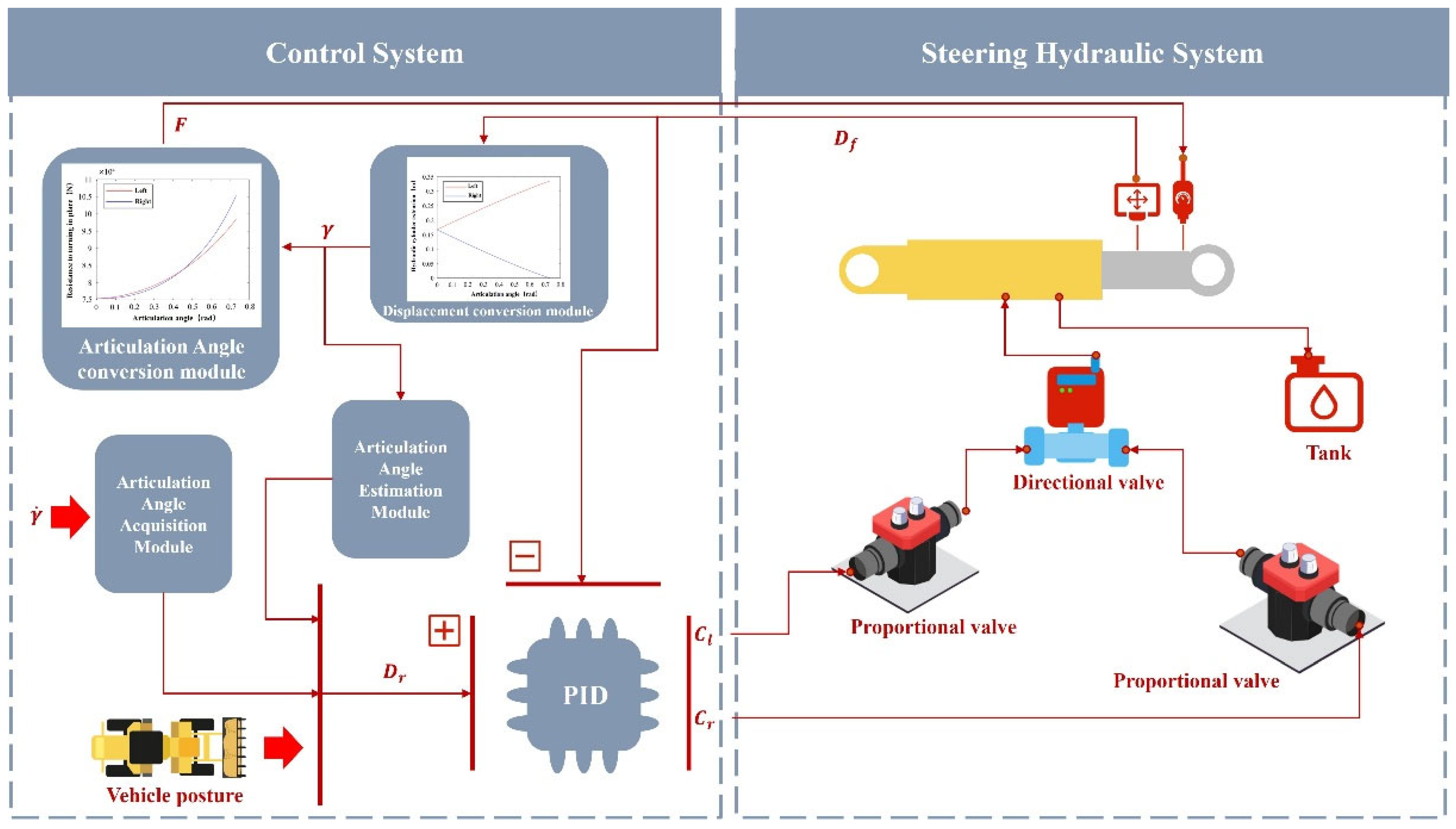
Traditional articulated vehicles typically employ a three-position six-way directional valve to control the steering cylinder. Based on this configuration, the steering hydraulic system shown in Figure 4 right was developed. The key parameters of the directional valve are summarized in Table 1. The control system is illustrated in Figure 4 left. In this system, the input is the articulation angular velocity γ ˙ , and the output is the articulation angle γ . The reference displacement of the hydraulic cylinder is denoted by D r , and the actual displacement is D f . Proportional–Integral–Derivative (PID) controller receives both signals and generates the control command C u , which is further processed by a control allocation module to activate either the left or right solenoid valve with inputs C l or C r , respectively. The actual displacement D f is converted into the articulation angle γ via a displacement-to-angle transformation module, as defined in Equation (4). This transformation is integrated into the control model to enable real-time estimation of γ . Building upon this, and inspired by Equation (7), a steering resistance term is further introduced into the system model as a function of the articulation angle. This term is realized through an articulation-angle-to-resistance conversion module that combines geometric formulation with empirical observations. By incorporating this steering resistance component, the model captures additional nonlinear dynamic effects present in real steering processes—particularly under load-bearing and terrain-changing conditions. This enhancement not only brings the dynamic representation closer to actual vehicle behavior but also contributes to improved robustness in control design and simulation fidelity under complex operating scenarios.
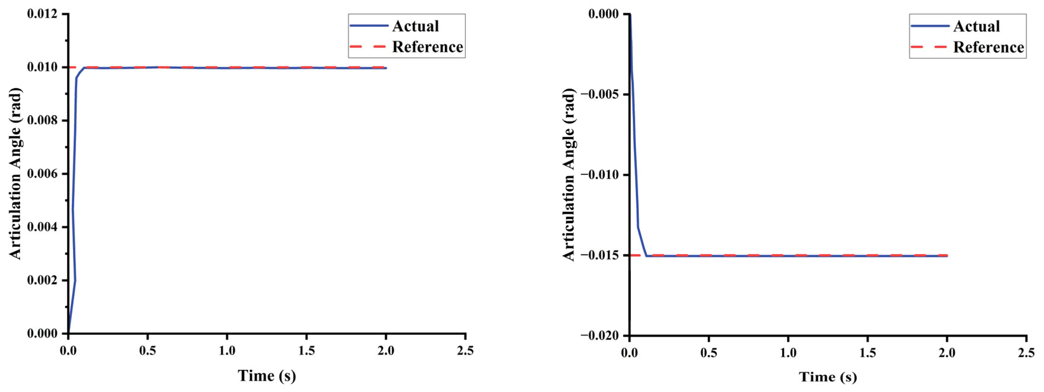
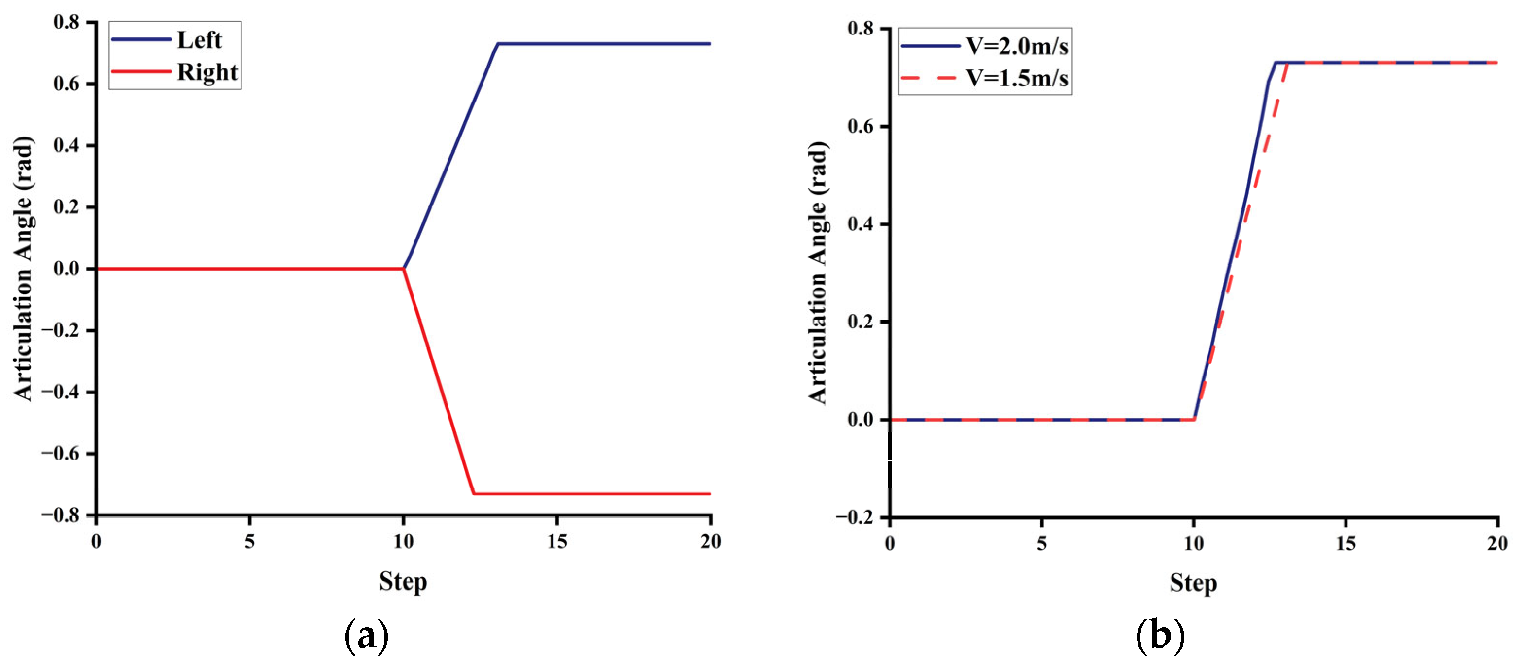
To verify the effectiveness of the proposed steering hydraulic control system described above, simulations were conducted with a sampling period of 0.05 s, applying articulation angular velocity inputs of 0.2 rad/s and −0.3 rad/s, respectively. The initial articulation angles in both cases were set to zero. As shown in Figure 5, the simulation results indicate that the steering control system model quickly stabilizes at the target reference articulation angle, demonstrating good dynamic response and stability.

3.3. Dynamic Response Characteristics of Articulated Vehicles

The underground mining loader, a typical articulated vehicle, exhibits complex dynamic responses including strong nonlinearities, significant electronic control system inertia, and delayed responses to control inputs. Investigating its dynamic response characteristics through systematic experiments is essential for accurately developing a comprehensive whole-vehicle dynamics model for articulated vehicles. Accordingly, this section presents a series of characteristic experiments on the underground mining loader, establishing the necessary experimental foundation for articulated vehicle modeling.
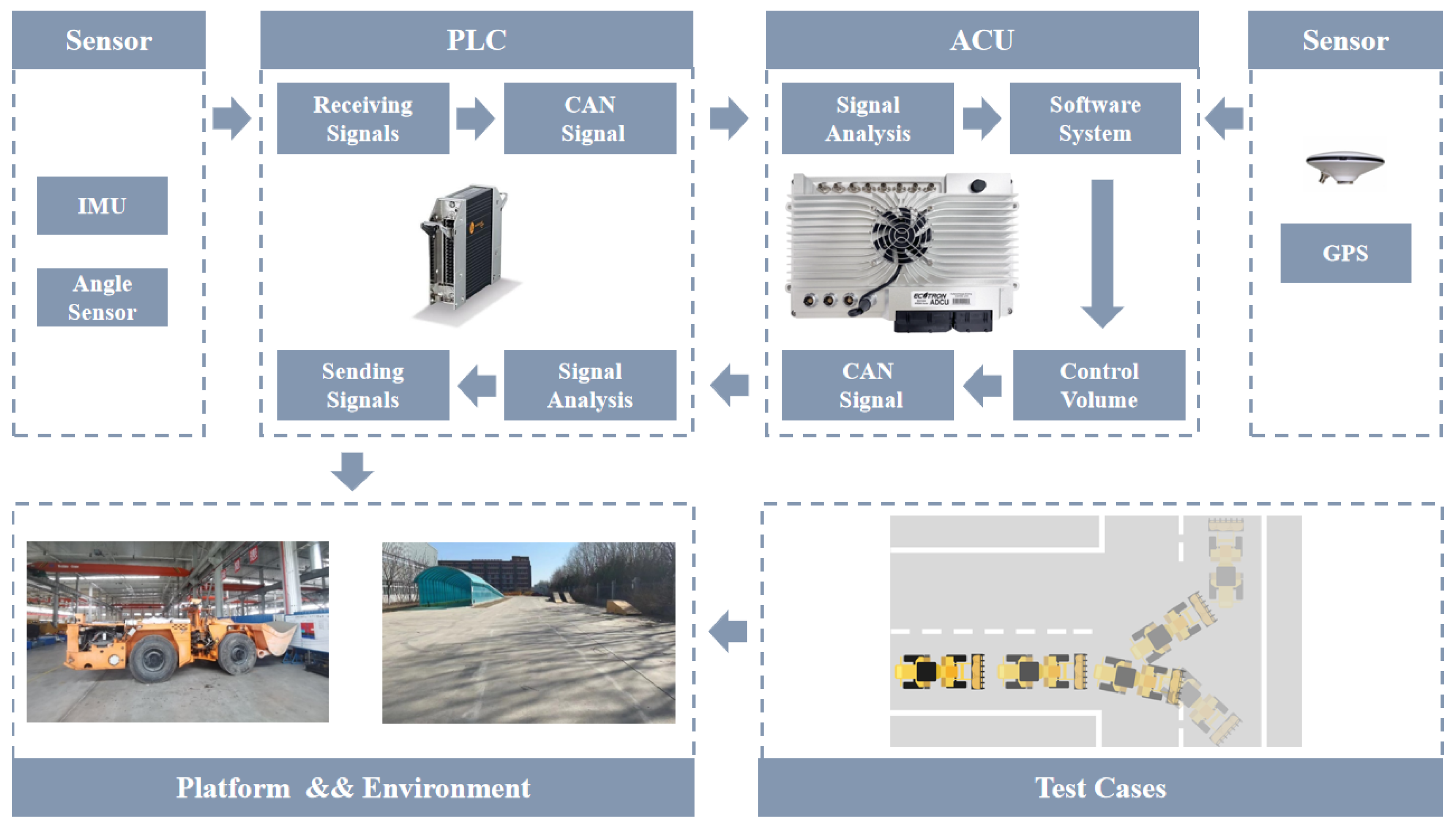
The experimental platform architecture is shown in Figure 6. Key measurement units such as IMU and angle sensors acquire data via a programmable logic controller (PLC) signal acquisition module, while communication with the central processing unit (ACU) is maintained through CAN signals. GPS data are transmitted directly to the ADCU via an RS-232 serial interface. The ACU runs test programs developed on the ROS framework, with all signal exchanges managed as ROS Topics to ensure synchronized and reliable data flow.
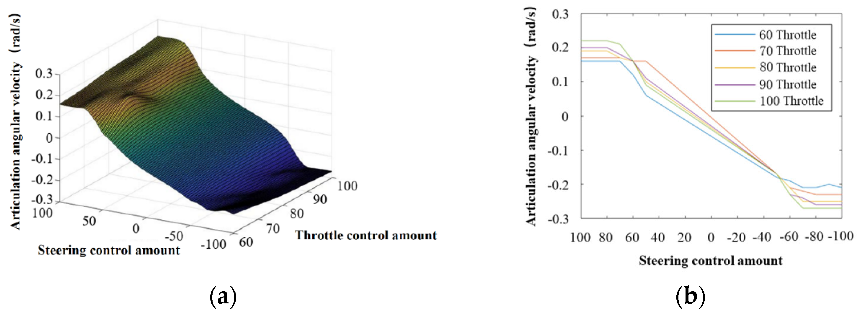
During the experiments, throttle and steering are indirectly controlled by electrical signals modulating the solenoid valve openings. The vehicle travels straight for the first 10 s before executing steering commands to turn left or right. Positive articulation angles denote left turns, whereas negative angles indicate right turns. Given that steering characteristics are less pronounced under low throttle inputs, the experimental design limits throttle control inputs to the range [60, 100] and steering control inputs to [−100, 100], with a tolerance of 5 units. A total of 540 test runs were performed to ensure comprehensive data coverage. Analysis of the results revealed a strong coupling between throttle and steering control inputs: achieving a desired articulation angular velocity requires coordinated control of both parameters. Figure 7b illustrates how articulation angular velocity varies with different steering control inputs. Due to the asymmetric placement of the hydraulic steering cylinder on the vehicle’s right side, articulation angular velocity differs between right and left turns under identical throttle settings.
Based on the coupling relationship between throttle and steering, a throttle–steering coupling module was developed and integrated with the previously established hydraulic steering control system to construct a comprehensive dynamics model of the articulated vehicle (Figure 2). To further validate these findings, the whole-vehicle dynamics model was subjected to the same control scenarios. As shown in Figure 8a, when vehicle speed and steering inputs are held constant, the model exhibits a maximum articulation angle limit of approximately 0.73 rad, with slower articulation angle changes during left turns compared to right turns. The right panel in Figure 8 demonstrates that increased vehicle speed leads to faster articulation angle changes under identical left-turn commands, validating the modeled coupling between vehicle speed and steering dynamics.

4. Multi-Timescale Nonlinear Model Predictive Path Tracking Control

This section presents the design methodology of the MTS-NMPC controller. To evaluate the impact of prediction horizon N p and vehicle speed on path tracking performance, a co-simulation was conducted.

4.1. MTS-NMPC-Based Controller

The study reveals that traditional NMPC controllers, which employ a fixed prediction horizon N p , exhibit significant limitations under complex operating conditions. Specifically, when the path curvature or vehicle speed varies sharply, an excessively short N p may result in insufficient prediction coverage, potentially leading to hazardous scenarios such as corner-cutting or vehicle instability. Conversely, an overly long N p can cause unnecessary computational overhead, thereby compromising the real-time performance of the control system. To address this critical issue, this paper proposes an adaptive parameter adjustment strategy based on the curvature radius R. By establishing the relationships between the prediction horizon N p ( R ) , the maximum allowable velocity v m a x ( R ) , and the curvature radius, the strategy enables dynamic optimization of control parameters. Specifically, these two key parameters are defined as follows:
N p v m a x = A R 2 + B R + C
where R = R 1 , R 2 , A = a 1 a 2 , B = b 1 b 2 , C = c 1 c 2 . The constant matrices A, B, and C were all obtained by measurements data. The constant matrices A, B, and C were obtained by fitting measurement data using quadratic spline curves. The datasets consisted of 120 measurements collected from vehicle tests, and the maximum fitting error was less than 0.005, ensuring an accurate approximation of the relationship between prediction horizon, maximum allowable velocity, and curvature radius.
This design is embedded into the original NMPC [28] optimization framework, resulting in the development of the MTS-NMPC controller with road curvature awareness. It should be noted that the prediction model adopted within the controller is formulated as a state-space representation given in Equation (9):
x ˙ f y ˙ f θ ˙ f γ ˙ = c o s θ f 0 sin θ f sin γ L f cos γ + L r 0 0 L r L f cos γ + L r 1 v f γ ˙
where v f is the velocity of the front vehicle body, θ f is the heading angle of the front vehicle body, γ is the articulation angle, L f is the distance from the front axle center to the articulation point, and L r is the distance from the rear axle center to the articulation point.
The core optimization problem of this controller can be formulated as the following objective function:
m i n   J R =   i = 1 N p ( R ) | | e t + i t | | Q 2 + i = 0 N c | | u t + i     t ) | | R 2 + ρ ε 2
s . t . 0.07 m / s   Δ v f   0.07   m / s 0.30 rad / s   γ ˙   0.30 rad / s 0.73 rad   γ   0.73 rad v f v m a x ( R )
In this formulation, term i = 1 N p ( R ) | | e t + i t | | Q 2 minimizes the trajectory tracking error E over the prediction horizon by using a state error weighting matrix Q (Equation (2)), while term i = 0 N c | | u t + i     t ) | | R 2 ensures the smoothness of control inputs through the control weighting matrix R. Term ρ ε 2 introduces a slack variable ε with its associated penalty weight ρ to guarantee the feasibility of the optimization problem. Notably, the prediction horizon N p is formulated as a function of the path curvature radius R, thereby reflecting the adaptive capability of the controller. Regarding constraints, real-vehicle implementation imposes strict physical limitations. The formulated constraints—covering fluctuations in velocity, articulation angle, and articulation angular velocity—account not only for actuator limitations but also incorporate curvature-based speed limits via v m a x , enhancing operational safety. This adaptive framework dynamically adjusts both the prediction horizon and speed constraints based on real-time path curvature. As a result, it effectively suppresses the corner-cutting behavior commonly observed in traditional controllers during sharp turns, enhances vehicle stability when navigating consecutive curves, and demonstrates particular suitability for handling abrupt curvature variations frequently encountered in underground mining environments. The adaptive prediction horizon introduces a multi-timescale characteristic: by varying the horizon according to the road curvature, the NMPC controller can dynamically adjust its temporal coverage, enabling the control strategy to handle segments with different curvature magnitudes within a unified framework.

4.2. Validation and Performance Evaluation of the MTS-NMPC Algorithm for Articulated Vehicle Path Tracking

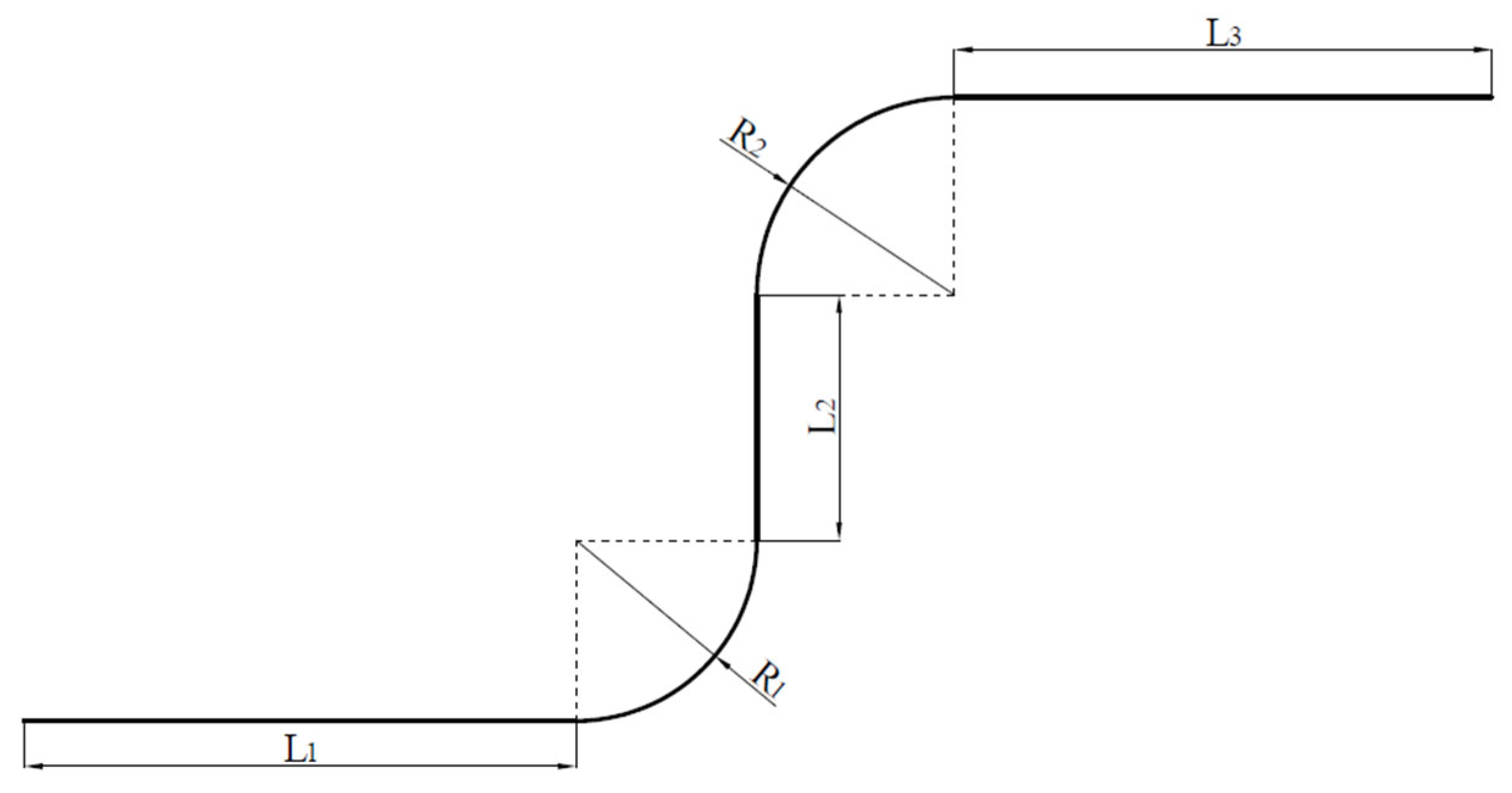
In this paper, the reference path shown in Figure 9 is constructed by means of a 5-segment function in order to carry out simulation experiments to study the effects of speed and prediction time domain on the performance of path tracking control.
In order to adaptively handle variations in road curvature along the reference path, a curvature-adaptive prediction horizon and reference speed adjustment strategy is implemented within the MTS-NMPC framework. This strategy computes the prediction horizon N p and the reference speed v r e f based on the local curvature of the path, ensuring that the controller maintains feasibility and achieves smooth trajectory tracking even under abrupt changes in road geometry. The detailed procedure is summarized in Algorithm 1.
Algorithm 1: Curvature-Adaptive prediction horizon and reference speed adjustment in MTS-NMPC.
StepDescription
InputVehicle state x k , reference path P , maximum horizon N p m a x , maximum allowable speed v m a x , sampling time T s
OutputPrediction horizon N p , reference speed v r e f , optimal control u k
InitializationSet previous horizon N p p r e v = N p m a x . This is used for warm-starting the MTS-NMPC optimization at the first step.
1. Curvature assessmentCompute maximum curvature k max within look-ahead window L = v · T s · N p m a x along P . Compute the corresponding radius R = 1 k m a x .
2. Prediction horizon and reference speed computationCalculate prediction horizon N p and reference speed v r e f using quadratic formulas:
N p = a 1 R 2 + b 1 R + c 1
v r e f = a 2 R 2 + b 2 R + c 2

Ensure N p N p m a x and v r e f v m a x .
3. Warm-start strategyIf N p < N p p r e v , truncate the previous optimal sequence.
If N p > N p p r e v , extend the sequence with reference-based guess.
Else, shift the previous sequence.
4. OptimizationSolve MTS-NMPC with horizon N p and reference speed v r e f using warm-start initialization. Apply soft constraints to ensure feasibility.
5. Control executionApply the first control element u * . Update N p p r e v N p .
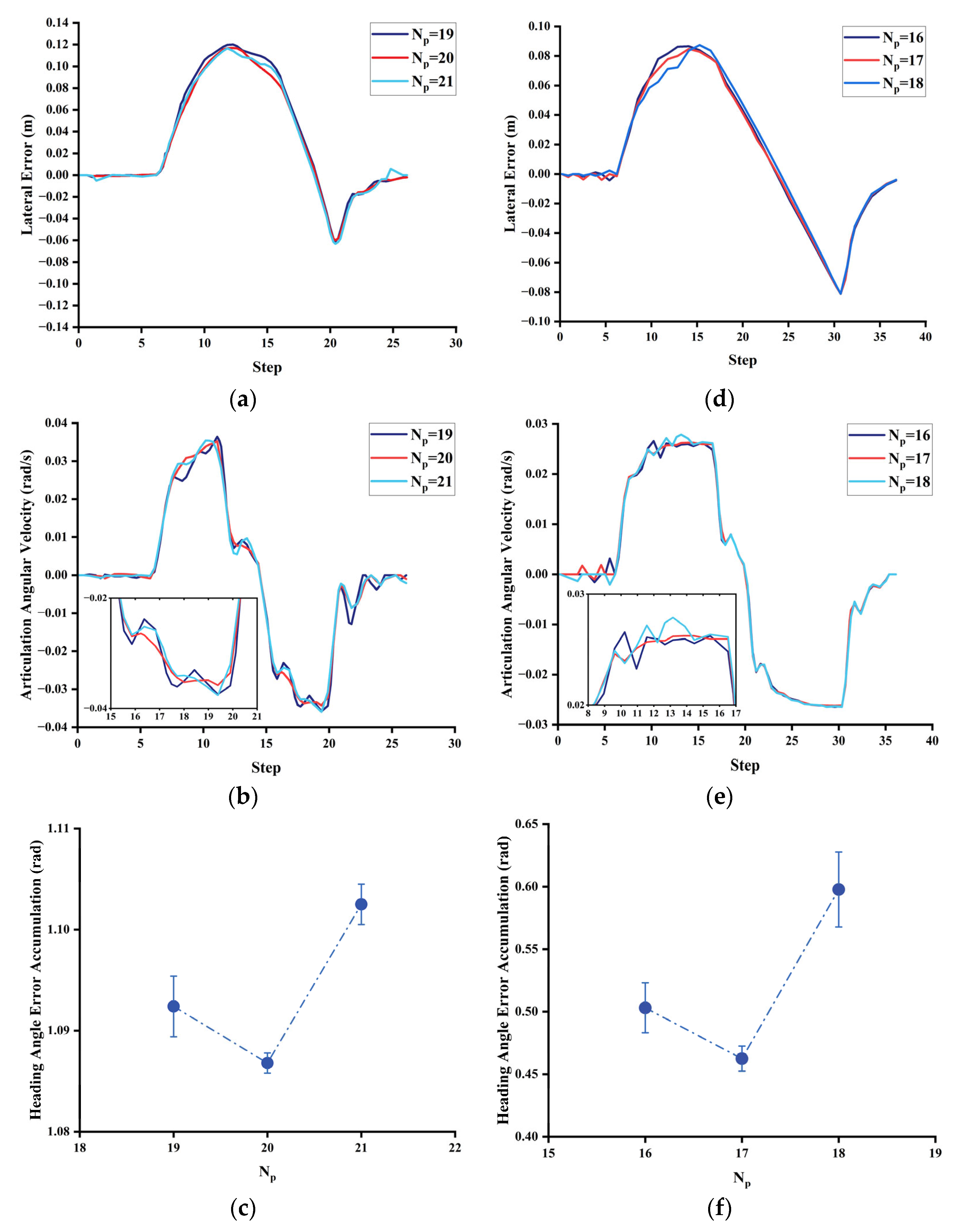
To validate the rationality of the proposed MTS-NMPC, we first performed a quantitative analysis of the traditional NMPC. The purpose is to study the relationship between the prediction time domain, maximum reference speed and turning radius (the same turning radius is used in this experiment). In Figure 10, diagrams (a), (b), and (c) show the lateral error, articulated angular velocity curve, and heading angle error accumulation of the NMPC controller with N p = 19, N p = 20, and N p = 21 at v = 3 m/s (the normal driving speed of articulated vehicles when carrying heavy loads, climbing slopes, or navigating rough terrains). The maximum lateral error of the NMPC controller with N p = 20 is smaller when v = 3 m/s, the reference steering radius R 1 = R 2 = 10 m, and the segment lengths L 1 = L 2 = L 3 = 20 m ; the change in articulated angular velocity is gentler, and the accumulation of heading angle error is minimal throughout the path tracking process. Similarly, as shown in Figure 10d–f, when the reference steering radius is R 1 = R 2 = 20 m, and the vehicle speed is v = 3 m/s, the optimal prediction horizon is found to be 17. After analyzing, it can be seen that: under the premise of constant speed, the larger the reference steering radius is, the smaller the tracking error is, and it can be known that there exists a maximum reference speed under a certain reference radius; on this basis, there also exists an optimal prediction time domain corresponding to this reference steering radius. In order to improve the efficiency of articulated vehicles, the maximum reference speed is used in the path tracking process in this paper.
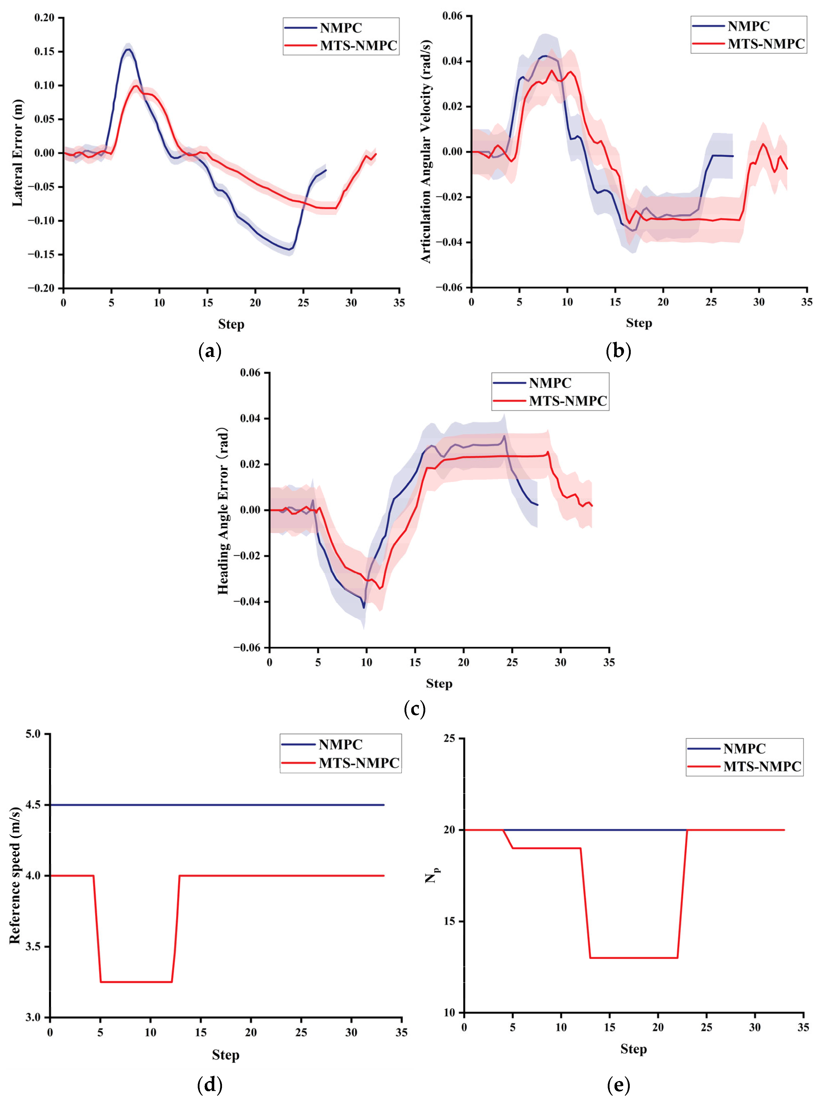
We performed simulation experiments to evaluate the control framework for articulated vehicle path tracking, as depicted in Figure 2. The steering radius of the reference paths are set to be R 1 = 15 m, R 2 = 35 m, respectively, in the simulation. A comparative experimental study is conducted. During the experiment, the maximum speed limit is set to 4.5 m/s, the starting reference speed of the experimental group (MTS-NMPC controller) is 4 m/s, and the starting prediction time domain is N p = 20; the reference speed of the control group (NMPC controller) is 4.5 m/s, and the prediction time domain is N p = 20. The comparison of the control effect and the changes in the reference speed and prediction time domain are shown in Figure 11a–c and Figure 11d,e, respectively. The figure shows that the control performance of the MTS-NMPC controller is significantly improved compared with the traditional NMPC controller, in the path tracking process, the maximum lateral error is reduced by 35%, the maximum heading error is reduced by 17% compared with the NMPC controller, and the degree of fluctuation of the articulated angular velocity is significantly reduced, which can improve the “twisting and swinging” problem of the vehicle to a certain extent. Different from the fuzzy logic switching MPC [24] that relies on error indicators, the MTS-NMPC in this paper dynamically adjusts the prediction time domain based on the path curvature directly, which avoids the complexity of fuzzy rule tuning parameterization, and is more suitable for scenarios with sudden curvature changes in deep shaft mines. Compared with the Corrected Model Predictive Control (CMPC) experiments [29], the MTS-NMPC proposed in this paper further reduces the heading angle error in the same curvature mutation section, which demonstrates the superiority of the dynamic prediction time domain mapping strategy.

5. Real-World Validation of MTS-NMPC in an Underground Mining Environment

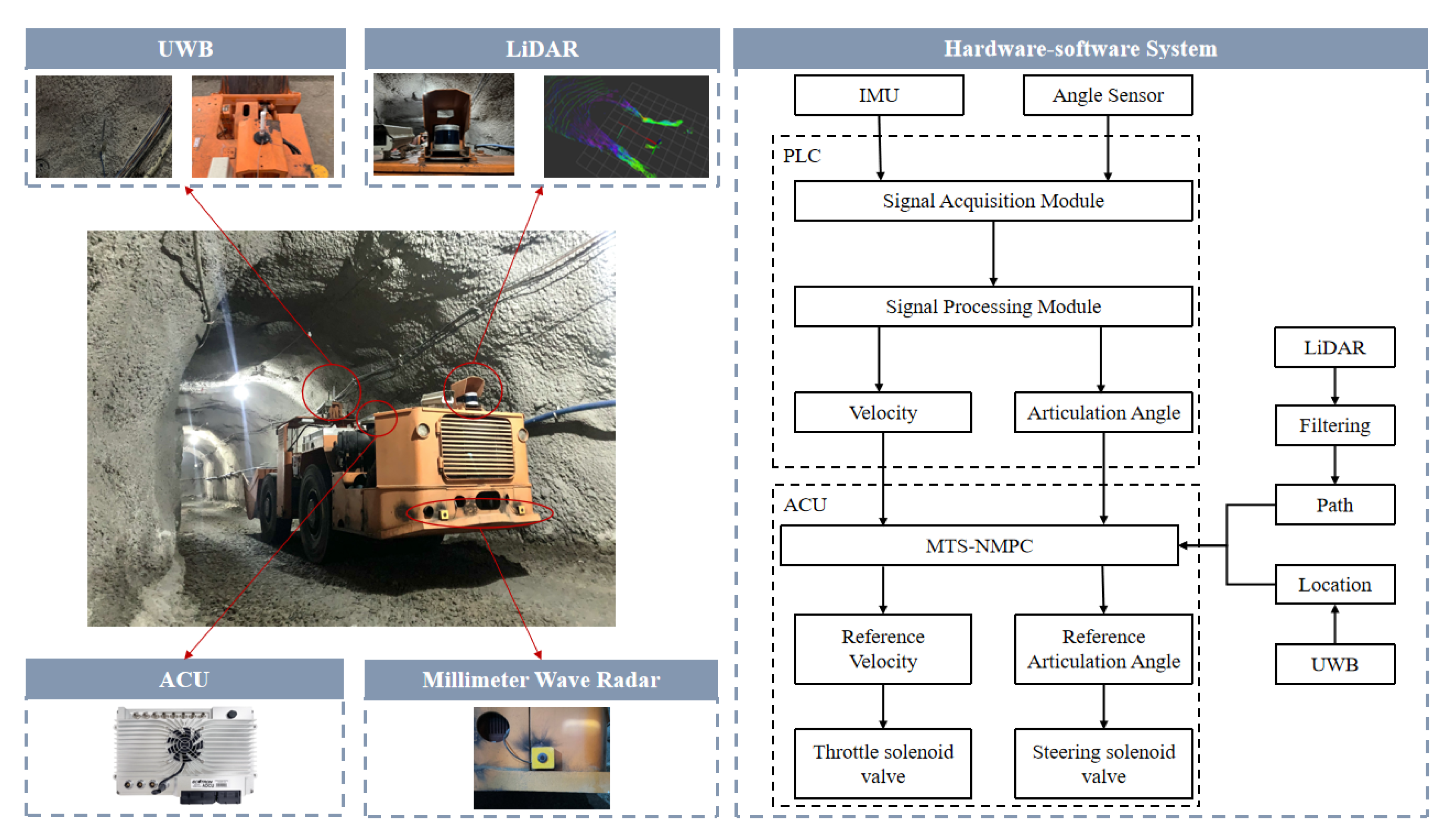
To experimentally validate the proposed MTS-NMPC controller in a realistic underground environment, a real-world field trial was conducted at a depth of 645 m in an operational mining site. The autonomous operation of the mining loader, enabled by an integrated unmanned control system, depends on the coordinated functioning of several key modules, including environmental perception, navigation, localization, path planning, and decision-making control. The hardware configuration consists of an Ultra-Wideband (UWB) navigation system for high-precision localization, an ACU, a PLC, an odometer, angle sensors, and other auxiliary components. Together, these modules facilitate real-time acquisition and processing of sensory and control data, enabling the implementation and validation of the MTS-NMPC-based path tracking algorithm.
The architecture of the integrated hardware–software system is illustrated in Figure 12 right. Measurement units such as the inertial measurement unit (IMU) and angle sensors acquire signals through a data acquisition module embedded within the PLC. These data are transmitted to the ACU via the Controller Area Network (CAN) bus, while the PLC simultaneously dispatches control commands to the vehicle’s actuators. ACU is based on ARM architecture, and is powered by Ubuntu 20.04. The main control chip is S32G274, which can ensure automotive-grade processing capabilities. All signal exchanges within the ACU are handled as ROS topics. To mitigate communication latency, each signal is timestamped upon acquisition. The engineering software we deployed is based on Python programming, and the MTS-NMPC solver uses the CasADi interface with IPOPT as the underlying nonlinear programming (NLP) solver and the MUMPS linear solver. The optimality tolerance and constraint violation tolerance are set to 1 × 10⁻⁶ and 1 × 10⁻⁴, respectively. A stable communication frequency of 50 Hz is maintained to ensure reliable data synchronization and low-latency signal transmission. On the S32G274 platform, the average computation time per control update at 50 Hz is 14.6 ms, with the worst-case time recorded at 18.9 ms. This leaves a timing headroom margin of approximately 5 ms to ensure stable real-time execution under varying computational loads. CPU utilization remains below 70% in all experiments, confirming sufficient processing capacity for real-time operation. In this study, filtered LiDAR point clouds are employed to extract the tunnel centerline, which serves as a stable reference trajectory for the controller. The curvature of the centerline is estimated by applying spline fitting within a 3 m moving window, followed by Savitzky–Golay smoothing with a polynomial order of 3 to suppress high-frequency fluctuations. Outliers are eliminated when their deviation from the fitted centerline exceeds 0.3 m. In parallel, the UWB positioning system provides real-time vehicle localization, and a communication latency of approximately 50 ms is explicitly compensated in the controller design. To reduce the effect of curvature estimation noise on the adaptive prediction horizon and the maximum reference speed, the curvature signal is further filtered with a first-order low-pass filter (cut-off frequency 0.5 Hz) and constrained within ±0.15 m−1, ensuring stable NMPC operation under underground mining conditions.
Figure 13 illustrates the right-turn maneuver of the loader at a consistent bend under identical speed conditions but with varying prediction horizons. The coordinate system’s origin is defined at the loader’s reference point, corresponding to the radar installation location. Specifically, Figure 13a–c correspond to prediction horizons of 15, 10, and 8, respectively. Using the spatial clearance between the vehicle and the tunnel walls as the evaluation criterion, the following observations are made: with a prediction horizon of 15, the loader veers too close to the right wall, increasing the risk of collision; with a horizon of 10, the vehicle maintains a safe and balanced distance from both tunnel walls and completes the turn successfully; with a horizon of 8, the vehicle remains excessively offset from the right wall, increasing the turning radius and raising the risk of contact with the left front wall. These findings underscore the significant influence of the prediction horizon on tracking accuracy, aligning with the observations discussed in Section 4.2.
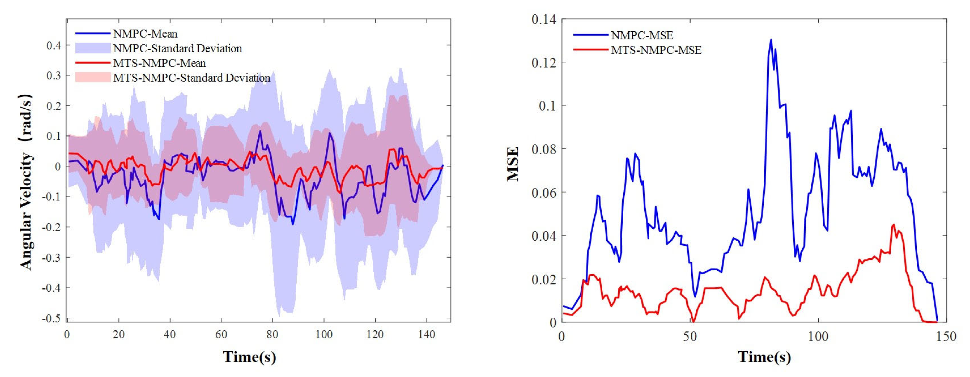
During path-tracking tasks, the stability of the articulated vehicle is evaluated using its articulation angular velocity, as shown in Figure 14. With a fixed prediction horizon, the conventional NMPC demonstrates significantly higher mean, standard deviation, and mean squared error (MSE) of articulation angular velocity compared to the proposed MTS-NMPC. These discrepancies lead to more pronounced jackknifing and swaying phenomena, particularly at higher speeds where oscillatory behavior intensifies vehicle instability. Given that path-tracking smoothness is a key performance metric for articulated vehicles, the MTS-NMPC effectively suppresses both jackknifing and swaying during complex maneuvers, thereby enhancing the overall stability of the system.

6. Discussion

This section provides a comprehensive discussion on the performance and characteristics of the proposed MTS-NMPC under real-world testing conditions. In the conducted experiments, both MTS-NMPC and standard NMPC maintained stable operation at 50 Hz, demonstrating real-time feasibility; this evaluation was performed using Python, and performance in other programming environments such as C++ was not assessed. The experiments were carried out in an underground mining environment, where scene mapping can be realized using LiDAR-based techniques and vehicle localization can be performed through point cloud registration. For the present experiments, the available UWB positioning system at the test site was utilized, indicating that UWB is not strictly required for vehicle localization.
The proposed method effectively adjusts the prediction horizon based on path curvature, enabling adaptive control that balances prediction coverage and computational demand. While MTS-NMPC introduces a modest increase in computational load compared with standard NMPC due to adaptive horizon calculations, the real-time performance remained satisfactory for the tested conditions. The approach demonstrates effective control performance for the tested articulated vehicle under varying curvature conditions; however, its applicability to other vehicle types, different mining layouts, or more complex operating scenarios requires further investigation.
Potential limitations of the current work include the reliance on accurate curvature estimation and the specific localization system employed, which should be taken into account when extending the method. Additionally, future work may explore integration with alternative perception and localization systems, evaluation under different vehicle dynamics, and quantitative performance assessment metrics such as RMS tracking error, maximum deviation, and articulation stability indices, to further substantiate the generality and robustness of the proposed approach.

7. Conclusions

The results collectively demonstrate the robustness and practical applicability of the MTS-NMPC method in addressing the challenges of path tracking in complex mining environments.

7.1. Validation of Steering Model Accuracy and Control Performance Enhancement

The steering system dynamics model, established through real-vehicle testing, accurately captures the nonlinear relationship between the hydraulic steering system and the articulation angular velocity. Experimental results confirm the model’s effectiveness in representing the steering behavior of articulated vehicles, including left–right steering asymmetry and speed–steering coupling effects. The MTS-NMPC controller, developed based on this model, effectively reduces path-tracking errors by dynamically adjusting both the prediction horizon and control inputs. In underground trials, the fluctuation in articulation angular velocity was reduced by 40%, and body oscillations were substantially suppressed, indicating strong adaptability to real-world operating conditions.

7.2. Adaptive Advantages and Performance Improvements of the Multi-Timescale Method

The proposed Multi-Timescale Nonlinear Model Predictive Control (MTS-NMPC) framework enables adaptive adjustment to varying path geometries by dynamically correlating road curvature, reference speed, and prediction horizon. Simulation and field experiments show that the method shortens the prediction horizon to improve responsiveness in sharply curved segments and extends it to enhance stability in smoother sections. Compared to conventional NMPC, MTS-NMPC reduces maximum lateral deviation by 35% and heading error by 17%, while also achieving smoother articulation angular velocity profiles. These improvements reflect the strategy’s ability to capture path dynamics in real time, thereby balancing tracking precision and computational efficiency.
The present study has primarily focused on analyzing the dynamic response characteristics of the articulated vehicle in an unladen state, which provides a foundational understanding of its baseline behavior. However, real-world operations often involve varying load conditions that can significantly influence vehicle dynamics. Therefore, future work will extend this investigation to encompass multiple loading scenarios, enabling a more comprehensive evaluation of vehicle performance and control strategy robustness across diverse operational contexts.
Furthermore, during the deep mine experimental phase, the implemented MTS-NMPC strategy was designed with a focus on the influence of the prediction horizon, while other relevant factors—such as varying vehicle speeds and external disturbances—were not extensively considered. In addition, the tests were conducted under low-speed conditions, which may limit the generalizability of the findings to higher-speed operations. Future research will aim to address these limitations by incorporating a wider range of dynamic constraints and operating speeds into the control framework.

Author Contributions

Conceptualization, L.L. and X.Z.; methodology, L.L.; software, L.L. and X.Z.; validation, L.L.; X.Z. and Y.K.; formal analysis, L.L. and X.Z.; resources, X.Z.; data curation, L.L. and X.Z.; writing—original draft preparation, L.L., Z.S. and X.Z.; writing—review and editing, Z.S. and Y.K.; visualization, Z.S. and X.Z.; funding acquisition, X.Z. and Y.K. All authors have read and agreed to the published version of the manuscript.

Funding

This research was funded by the National Key R&D Program—Key Special Project, grant number No.: 2023YFC2907405.

Data Availability Statement

The data in this study are available under the permission of all the authors.

Conflicts of Interest

The authors declare no conflicts of interest.

Abbreviations

The following abbreviations are used in this manuscript:
MTS-NMPCMulti-Time-Scale-Nonlinear Model Predictive Control
NMPCNonlinear Model Predictive Control
AVArticulated Vehicle
ATVAll-Terrain Vehicle
AMPCAdaptive Model Predictive Controller
FARFront Axle Reference
ARAdaptive Reference
SRP-LMPCSingle Reference Point-Linear Model Predictive Control
MRP-LMPCMultiple Reference Points-Linear Model Predictive Control
VTFVirtual Terrain Field of Dynamic Simulation
ASV Articulated Steering Vehicle

References

  1. Qu, J.; Zhang, Z.; Qin, Z.; Guo, K.; Li, D. Applications of Autonomous Navigation Technologies for Unmanned Agricultural Tractors: A Review. Machines 2024, 12, 218. [Google Scholar] [CrossRef]
  2. Yao, Q.; Tian, Y.; Wang, Q.; Wang, S. Control Strategies on Path Tracking for Autonomous Vehicle: State of the Art and Future Challenges. IEEE Access 2020, 8, 161211–161222. [Google Scholar] [CrossRef]
  3. Chu, S.; Xie, Z.; Wong, P.K.; Li, P.; Li, W.; Zhao, J. Observer-based gain scheduling path following control for autonomous electric vehicles subject to time delay.Vehic. Syst. Dyn. 2021, 60, 1602–1626. [Google Scholar] [CrossRef]
  4. Zhang, C.; Gao, G.; Zhao, C.; Li, L.; Li, C.; Chen, X. Research on 4WS Agricultural Machine Path Tracking Algorithm Based on Fuzzy Control Pure Tracking Model. Machines 2022, 10, 597. [Google Scholar] [CrossRef]
  5. Deshmukh, D.; Kumutham, A.R.; Pratihar, D.K.; Deb, A.K. Accurate Path Tracing of a Tracked Robot: A Modified PID Approach with Slip Compensation. Eng. Res. Express 2025, 7, 015203. [Google Scholar] [CrossRef]
  6. Cui, D.; Wang, G.; Zhao, H.; Wang, S. Research on a Path-Tracking Control System for Articulated Tracked Vehicles. J. Mech. Eng. Stroj. Vestn. 2020, 66, 311–324. [Google Scholar] [CrossRef]
  7. Dou, F.; Huang, Y.; Liu, L.; Wang, H.; Meng, Y.; Zhao, L. Path planning and tracking for autonomous mining articulated vehicles. Int. J. Heavy Veh. Syst. 2019, 26, 315–333. [Google Scholar] [CrossRef]
  8. Huang, Y.; Tian, Z.; Jiang, Q.; Xu, J. Path Tracking Based on Improved Pure Pursuit Model and PID. In Proceedings of the 2020 IEEE 2nd International Conference on Civil Aviation Safety and Information Technology, Weihai, China, 14–16 October 2020. [Google Scholar]
  9. Hu, C.; Ru, Y.; Li, X.; Fang, S.; Zhou, H.; Yan, X.; Liu, M.; Xie, R. Path tracking control for brake-steering tracked vehicles based on an improved pure pursuit algorithm. Biosyst. Eng. 2024, 242, 1–15. [Google Scholar] [CrossRef]
  10. Hu, K.; Cheng, K. Trajectory Planning for an Articulated Tracked Vehicle and Tracking the Trajectory via an Adaptive Model Predictive Control. Electronics 2023, 12, 1988. [Google Scholar] [CrossRef]
  11. Sun, N.; Zhang, W.; Yang, J. Integrated Path Tracking Controller of Underground Articulated Vehicle Based on Nonlinear Model Predictive Control. Appl. Sci. 2023, 13, 5340. [Google Scholar] [CrossRef]
  12. Meng, Y.; Gan, X.; Bai, G. Path following control of underground mining articulated vehicle based on the preview control method. Chin. J. Eng. 2019, 41, 662–671. [Google Scholar]
  13. Zhou, B.; Su, X.; Yu, H.; Guo, W.; Zhang, Q. Research on Path Tracking of Articulated Steering Tractor Based on Modified Model Predictive Control. Agriculture 2023, 13, 871. [Google Scholar] [CrossRef]
  14. Awad, N.; Lasheen, A.; Elnaggar, M.; Kamel, A. Model predictive control with fuzzy logic switching for path tracking of autonomous vehicles. ISA Trans. 2022, 129, 193–205. [Google Scholar] [CrossRef] [PubMed]
  15. Rokonuzzaman, M.; Mohajer, N.; Nahavandi, S. Effective adoption of vehicle models for autonomous vehicle path tracking: A switched MPC approach. Vehic. Syst. Dyn. 2022, 61, 1236–1259. [Google Scholar] [CrossRef]
  16. Stano, P.; Montanaro, U.; Tavernini, D.; Tufo, M.; Fiengo, G.; Novella, L.; Sorniotti, A. Model predictive path tracking control for automated road vehicles: A review. Annu. Rev. Control 2023, 55, 194–236. [Google Scholar] [CrossRef]
  17. Wang, M.; Niu, C.; Wang, Z.; Jiang, Y.; Jian, J.; Tang, X. Model and Parameter Adaptive MPC Path Tracking Control Study of Rear-Wheel-Steering Agricultural Machinery. Agriculture 2024, 14, 823. [Google Scholar] [CrossRef]
  18. Tang, X.; Yan, Y.; Wang, B.; Zhang, L. Adaptive Articulation Angle Preview-Based Path-Following Algorithm for Tractor-Semitrailer Using Optimal Control. Sensors 2022, 22, 5163. [Google Scholar] [CrossRef]
  19. Yu, H.; Zhao, C.; Li, S.; Wang, Z.; Zhang, Y. Pre-Work for the Birth of Driver-Less Scraper (LHD) in the Underground Mine: The Path Tracking Control Based on an LQR Controller and Algorithms Comparison. Sensors 2021, 21, 7839. [Google Scholar] [CrossRef]
  20. Liu, J.; Zhao, X.; Guo, H.; Chen, H. Tractor Semi-trailer Modeling and Regional Path Tracking Control Strategy. In Proceedings of the 2020 Chinese Automation Congress (CAC), Shanghai, China, 6–8 November 2020; pp. 1961–1966. [Google Scholar]
  21. Zhang, Z.; Xie, L.; Lu, S.; Wu, X.; Su, H. Vehicle yaw stability control with a two-layered learning MPC. Vehic. Syst. Dyn. 2022, 61, 423–444. [Google Scholar] [CrossRef]
  22. Lee, T.; Jeong, Y. A Tube-Based Model Predictive Control for Path Tracking of Autonomous Articulated Vehicle. Actuators 2024, 13, 164. [Google Scholar] [CrossRef]
  23. Rahman, S.; Gordon, T.; Gao, Y.; Henderson, L.; Liu, Q.; Laine, L. Automated steering control for improved path tracking and stability of articulated heavy goods vehicles. Vehic. Syst. Dyn. 2024, 62, 1–21. [Google Scholar] [CrossRef]
  24. Chen, X.; Cheng, J.; Hu, H.; Shao, G.; Gao, Y.; Zhu, Q. A Novel Fuzzy Logic Switched MPC for Efficient Path Tracking of Articulated Steering Vehicles. Robotics 2024, 13, 134. [Google Scholar] [CrossRef]
  25. Bai, G.; Liu, S.; Zhou, B.; Huang, J.; Zheng, Y.; Elham, E. Path Tracking for Electric Mining Articulated Vehicles Based on Nonlinear Compensated Multiple Reference Points Linear MPC. World Electr. Veh. J. 2024, 15, 427. [Google Scholar] [CrossRef]
  26. He, Y.; Wu, J.; Xu, F.; Liu, X.; Wang, S.; Cui, G. Path Tracking Control Based on T-S Fuzzy Model for Autonomous Vehicles with Yaw Angle and Heading Angle. Machines 2024, 12, 375. [Google Scholar] [CrossRef]
  27. de Lima, M.L.; Camponogara, E.; Odloak, D.; Jordanou, J.P. Satisficing Infinite-Horizon Model Predictive Control. J. Process Control 2025, 150, 103423. [Google Scholar] [CrossRef]
  28. Li, Y.; Dong, W.; Zheng, T.; Wang, Y.; Li, X. Scene-Adaptive Loader Trajectory Planning and Tracking Control. Sensors 2025, 25, 1135. [Google Scholar] [CrossRef]
  29. Xu, L.; Hou, J.; Yan, X.; Liu, M.; Zhang, J.; Tao, Y. Research on Path Tracking of Intelligent Hybrid Articulated Tractor Based on Corrected Model Predictive Control. World Electr. Veh. J. 2025, 16, 161. [Google Scholar] [CrossRef]
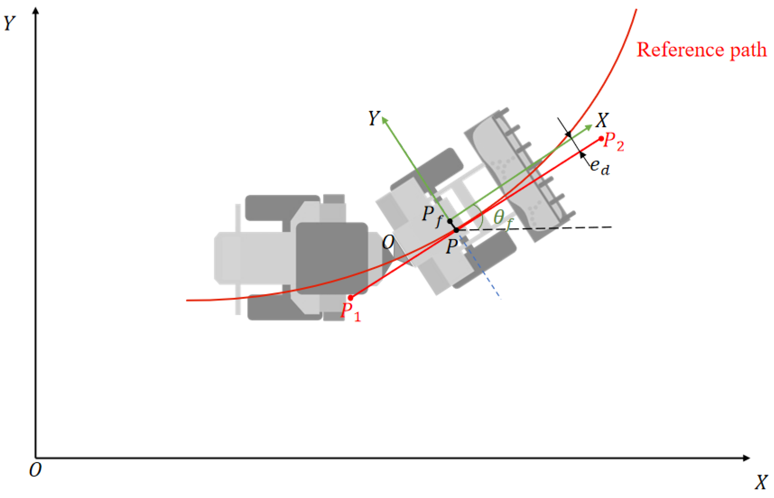
Figure 1. Articulated vehicle path tracking model.
Actuators 14 00477 g001
Figure 2. Framework of the MTS-NMPC-Based Path Tracking Control for Articulated Vehicle.
Actuators 14 00477 g002
Figure 3. Articulated vehicle steering mechanism (single cylinder one side arrangement).
Actuators 14 00477 g003
Figure 4. Steering hydraulic control system.
Actuators 14 00477 g004
Figure 5. Verification of the steering hydraulic control system; ((left) panel   γ ˙ = 0.2   r a d / s , (right) panel   γ ˙ = 0.3   r a d / s ).
Actuators 14 00477 g005
Figure 6. Experimental platform for real vehicle.
Actuators 14 00477 g006
Figure 7. Diagram of steering characteristics. (a) Throttle–steering-articulated angular velocity relationships. (b) Steering control volume-articulated angular velocity relationships.
Actuators 14 00477 g007
Figure 8. Characteristics of articulation angle. (a) Variation in articulation angle with the same control volume. (b) Variation in articulation angle with velocity coupling.
Actuators 14 00477 g008
Figure 9. Reference path.
Actuators 14 00477 g009
Figure 10. Optimal predicted time domain corresponding to different reference steering radii for v = 3 m/s (sampling period T = 0.05 s).
Actuators 14 00477 g010
Figure 11. Comparison of control effects, reference speeds, and predicted time-domain variations ((ac): control effects; (d,e): reference velocities; predicted time-domain variations), showing mean ± standard deviation over three experiments (sampling period T = 0.05 s).
Actuators 14 00477 g011
Figure 12. Structure of the unmanned system of the experimental shoveling machine.
Actuators 14 00477 g012
Figure 13. Comparison of path tracking effects with the same speed but different prediction time domains. The background shows the point cloud of the underground tunnel, the red curves represent the vehicle’s trajectories along the reference path, and the yellow boxes indicate the vehicle.
Actuators 14 00477 g013
Figure 14. Temporal Variation in Articulated Angle Velocity: Control Performance Comparison Between NMPC and MTS-NMPC (Results averaged over three experiments with standard deviation).
Actuators 14 00477 g014
Table 1. Simulation parameters of the three-position six-way directional valve.
ParameterValue
Spool outer diameter19 mm
Valve stem diameter9 mm
Spool mass1 kg
Spring stiffness8 N/mm
Disclaimer/Publisher’s Note: The statements, opinions and data contained in all publications are solely those of the individual author(s) and contributor(s) and not of MDPI and/or the editor(s). MDPI and/or the editor(s) disclaim responsibility for any injury to people or property resulting from any ideas, methods, instructions or products referred to in the content.