Article

Dual Halbach Array Compact Linear Actuator with Thrust Characteristics Part I Simulation Result

1
Course of Science and Technology, Tokai University, 4-1-1 Kitakaname, Hiratsuka 259-1292, Kanagawa, Japan
2
Research Institute of Science and Technology, Tokai University, 4-1-1 Kitakaname, Hiratsuka 259-1292, Kanagawa, Japan
3
Course of Mechanical Engineering, Tokai University, 4-1-1 Kitakaname, Hiratsuka 259-1292, Kanagawa, Japan
4
Mechanical Engineering, National Institute of Technology, Numazu College, 3600 Ooka, Numazu 410-8501, Shizuoka, Japan
5
Department of Electronic Robot Engineering, Aichi University of Technology, 50-2 Manori, Nishihazama-cho, Gamagori 443-0047, Aichi, Japan
6
Department of Mechanical Engineering, Tokyo University of Technology, 1404-1 Katakura-machi, Hachioji-shi 192-0982, Tokyo, Japan
7
Department of Mechanical Engineering, Hokkaido University of Science, 4-1, 7-jo 15-chome, Maeda, Teine-ku, Sapporo-shi 006-8585, Hokkaido, Japan
8
Department of Electrical Engineering, Fukuoka Institute of Technology, 3-30-1 Wajirohigashi, Higashi-ku, Fukuoka-shi 811-0295, Fukuoka, Japan
9
Department of Mechanical Systems Engineering, Tokai University, 4-1-1 Kitakaname, Hiratsuka 259-1292, Kanagawa, Japan
*
Author to whom correspondence should be addressed.
Actuators 2025, 14(10), 476; https://doi.org/10.3390/act14100476
Submission received: 25 July 2025 / Revised: 23 September 2025 / Accepted: 26 September 2025 / Published: 28 September 2025
(This article belongs to the Section High Torque/Power Density Actuators)

Abstract

The application of mechanical products in many situations involves linear motion. The cylinder head of an internal combustion engine (ICE), a mechanical product, contains intake and exhaust valves. These valves open or close using the linear motion converted by the camshafts rotated by the engine. A typical engine is operated with a single cam profile; depending on the engine rotation, there are areas where the cam profiles do not match, resulting in a poor engine performance. An intake and exhaust system with an actuator can solve this problem. In a previous study on this system, the geometry and processing during manufacturing were complex. Therefore, in response, a linear actuator operated by Lorentz force with a coil as the mover was designed in this study. Through an electromagnetic field analysis using the finite element method, a three-phase alternating current was applied to the coil, assuming that it would be used as a power source for a general inverter. Consequently, the thrust obtained in the valve-actuation direction was 56.7 N, indicating improved axial thrust over the conventional model.

1. Introduction

In mechanical products, rotational power from a motor is generally converted into linear motion by means of cam mechanisms, crank mechanisms, rack-and-pinion systems, worm gears, and similar devices. In addition, the operating characteristics, such as motion patterns, can be altered in accordance with operating conditions to enhance performance. However, because such variable mechanisms increase system complexity, they are typically adopted only when special performance improvements are required; in most ordinary products these mechanisms are not employed. An application of these systems is found in the intake and exhaust valves located in the cylinder head of an internal combustion engine (ICE), as illustrated in Figure 1. The motion of these valves is determined by the cam profile, which governs the valve lift and timing. Because the cam shape strongly influences combustion characteristics, it is a critical parameter that directly affects engine power and fuel economy. In conventional engines, however, the cam profile is not optimized across the entire operating range, and in some regimes engine performance is degraded as a result. To address this issue, mechanisms that switch the cam profile according to engine speed have been proposed. Such systems are implemented in sports cars to improve driving performance and in some mass-production vehicles to enhance fuel efficiency. Nevertheless, because these systems rely on multiple cam shapes, it is impossible to operate the engine valves with fully optimal parameters under continuously varying ICE speeds. Moreover, the cam shapes and valve motion patterns are constrained to avoid mechanical problems such as surging and valve jump. As a solution, systems that drive engine valves with linear actuators instead of cam mechanisms have been proposed [1]. These systems allow the valves to be controlled with optimal motion patterns corresponding to engine speed without mechanical constraints. They also make it possible to vary engine output in response to accelerator-pedal input without using a throttle valve, thereby improving combustion efficiency and consequently enhancing both power and fuel economy. Owing to these advantages, several studies have investigated linear actuators for engine-valve driving. However, despite the movers being equipped with substantial yokes, the high inductance and mover mass have made precise operation at the rotational speeds required for ICEs difficult [2].
Therefore, the present study focuses on voice-coil motors, which are capable of high-speed, high-precision operation and are widely used for hard-disk-drive head positioning [3,4,5,6,7]. Because a voice-coil motor employs a low-inductance solenoid coil as the mover, it can achieve high responsiveness and precise motion [8]. We have investigated a linear actuator for engine-valve driving that uses such a low-inductance solenoid coil as its mover and have confirmed its thrust characteristics [9]. Nevertheless, improving engine output necessitates not only increasing rotational speed but also achieving high torque, which in turn requires introducing as much fresh charge as possible into the combustion chamber. To accomplish this, the intake valve must be opened as widely as possible and held open for a longer duration. Ideally, the valve displacement should approach a quasi-rectangular profile. Consequently, the actuator must generate higher thrust to realize these motions. However, increasing the thrust force not only enlarges the actuator but also raises the electrical power demand, which in turn necessitates a larger power supply. Given the limited packaging space in the cylinder head and vehicle, installing bulky actuators or power units is impractical. Therefore, a compact linear actuator that delivers high thrust with minimal power and packaging overhead is required.
Previous studies have proposed actuators employing axially magnetized permanent magnets in the stator, but their thrust was limited to approximately 20 N, which was inadequate for the intended performance, and achieving higher thrust required enlarging the actuator [10]. To overcome this problem, Halbach arrays, which concentrate the magnetic flux of permanent magnets to increase thrust, have been investigated. In addition, double-Halbach arrays, in which Halbach arrays are arranged both inside and outside the solenoid coil, have been examined to further enhance thrust [11,12,13,14,15,16]. Owing to their low inductance, high responsiveness, and capability to generate large thrust, such actuators are expected to enable large-stroke operation; however, their thrust characteristics have not yet been fully explored. In this study aims to demonstrate, by means of the basic configuration of a VCM-type linear actuator whose voice-coil-motor stator is equipped with a dual Halbach array and three-phase alternating current, that continuous net thrust over one electrical cycle required for reciprocating valve operation in internal combustion engines can be realized, and to quantify its thrust characteristics by finite-element analysis. In addition, it investigates whether, without changing the hardware (geometry or materials), optimization of the initial phase of the three-phase alternating current (phase-only adjustment) can improve the cycle-averaged thrust over one electrical cycle; if so, it investigates where the optimal phase is located. The analysis is limited to quasi-static finite-element evaluations of thrust characteristics. The dynamic synthesis of the valve-lift (opening) profile and closed-loop control under engine operating conditions are beyond the scope of this paper and are left for future work.

2. Materials and Methods

2.1. Magnetic Field with Dual Halbach Array

In this study, we focused on the Halbach array shown in Figure 2a and its capability to concentrate magnetic flux in a single direction. In Figure 2a, “N” and “S” denote the magnetic poles, the solid lines represent magnetic field lines, and the arrows indicate the direction of the magnetic flux. In a conventional N–S array, the N and S poles are arranged alternately, so the magnetic field is distributed uniformly. By contrast, a Halbach array concentrates the magnetic field on one side of the magnets. Moreover, as illustrated in Figure 2b, a double-Halbach array, in which two rows of Halbach magnets face each other, can generate an even stronger magnetic field. Therefore, the present study adopts a dual-Halbach configuration for the linear actuator.

2.2. Principle of Operating a Linear Actuator with Three-Phase Alternating Current

In this section, the fundamental operating principle of a linear actuator driven by a three-phase alternating-current (AC) power supply is explained, as illustrated in Figure 3a. This figure presents a schematic cross section of the linear actuator employed in the present study. In Figure 3a, the rectangles denote permanent magnets, and the arrows inside each magnet indicate the magnetization direction. The rectangle positioned between the permanent magnets represents the coil. Two arrows drawn vertically through the permanent magnets and the coil show the paths of the magnetic flux, while the arrow extending rightward from the coil indicates the direction of the Lorentz force acting on the coil. In this configuration, four permanent magnets are used for the three coils to which the three-phase AC is applied. Figure 3b displays the three-phase AC waveforms flowing through the three coils. The solid line corresponds to the current in Coil 1, the dashed line to Coil 2, and the dash-dot line to Coil 3. These waveforms reveal that Coil 1 carries a positive current, whereas Coils 2 and 3 carry negative currents. According to Fleming’s left-hand rule, when magnetic flux exists in the +x direction, the Lorentz force acts in the y direction. Likewise, when the flux is oriented in the –x direction, the Lorentz force still acts in the y direction. Consequently, applying three-phase AC and arranging four permanent magnets yield a Lorentz force that drives the coil in the y direction.
Next, Step 2 shown in Figure 4 is considered. At this stage, the current phase is shifted by 90°. From the three-phase waveforms it follows that no current flows in Coil 1, a negative current flows in Coil 2, and a positive current flows in Coil 3. As a result, in the pink flux region of Figure 4a the flux points toward –x and the current flows in the –z direction. Under these conditions, Fleming’s left-hand rule indicates that the Lorentz force acts in the y direction. Conversely, in the green flux region the flux points toward +x and the current flows in the +z direction, so the Lorentz force acts in the +x direction. Therefore, even when the current phase is shifted by 90°, the coil continues to experience a Lorentz force. Subsequently, in Step 3 the current phase shifts by an additional 180°, and the arrangement changes as depicted in Figure 5.
Continuing this process moves the actuator to Step 4 (Figure 6) and further to Step 5 (Figure 7), at which point the magnetic-field configuration effectively returns to that of the 0° state. By repeatedly cycling through these steps, the coil is driven stepwise in the y direction. Thus, although the phase of the current varies, the Lorentz force persists, ensuring that the coil moves continuously along the y-axis.

2.3. Geometry and Dimensions of the 3D Model

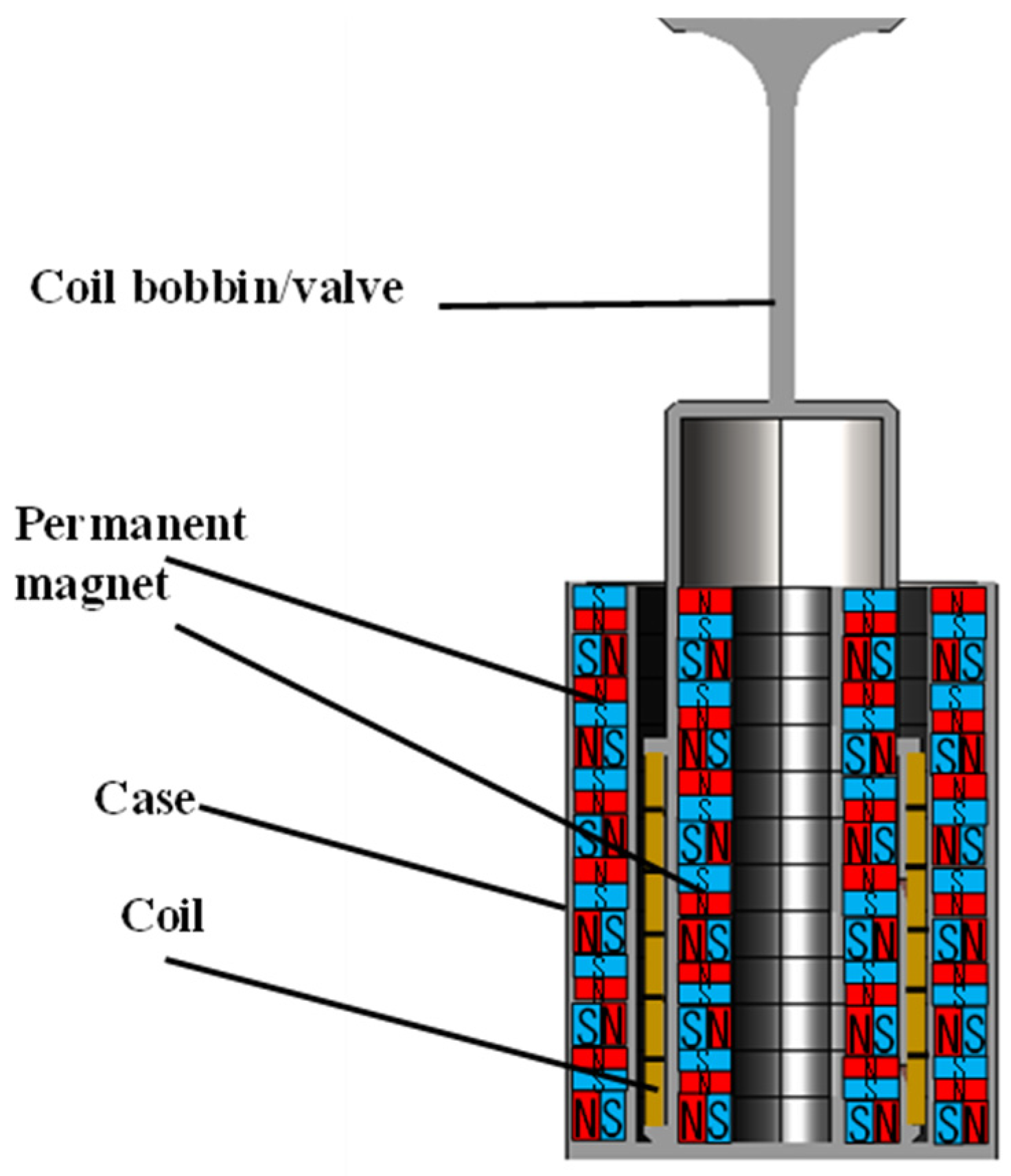
In this study, the electromagnetic characteristics of the linear actuator were evaluated using the three-dimensional model shown in Figure 8. The analysis model contains six densely arranged cylindrical coils, and twelve permanent cylindrical magnets are positioned both inside and outside these coils. Additional principal components—a valve, a bobbin, and an outer casing—are also included. The coils, valve, and bobbin constitute the moving assembly, whereas the permanent magnets and outer casing function as the stator, thereby faithfully reproducing the actuator’s operating environment.
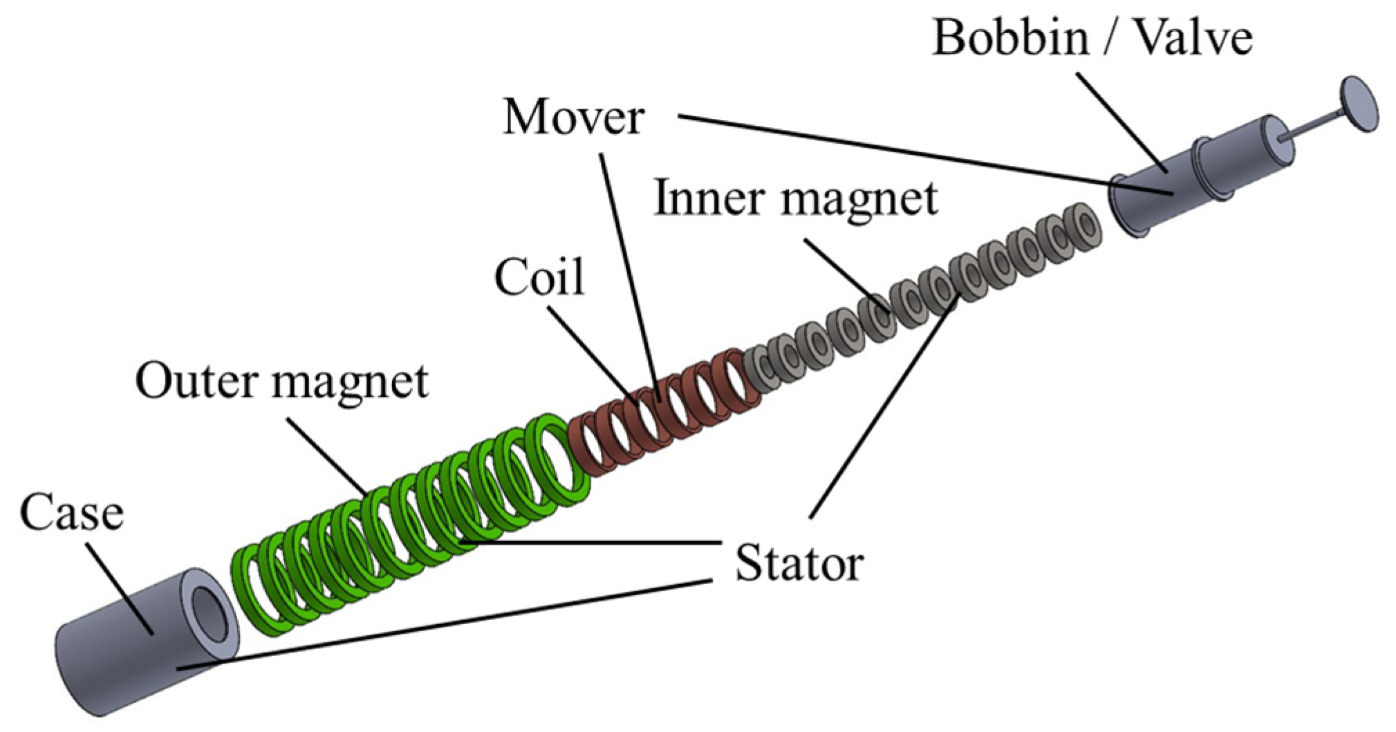
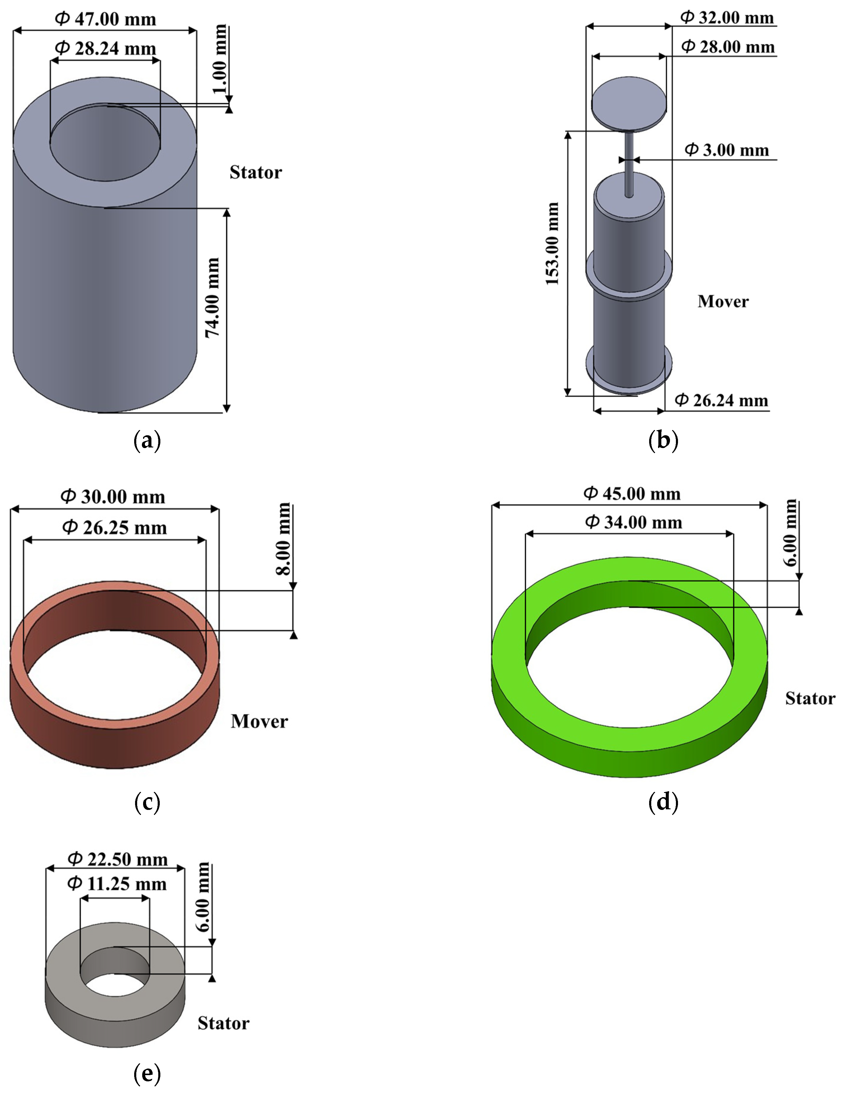
Figure 9 through Figure 10 present an exploded view of the analysis model and its individual parts. Figure 9 depicts the actuator’s exploded view. The actuator consists of 32 components in total: six coils, one combined bobbin-valve, one outer yoke, twelve outer magnets, and twelve inner magnets. Each dual-Halbach stator consists of an inner and outer magnet array. Within each array, a four-magnet set (alternating axial and radial magnetization directions) is used as the basic unit. An inner four-magnet set and its opposing outer four-magnet set together form one magnetic circuit that concentrates flux into the coil region. Each array comprises three four-magnet sets (12 magnets per array), yielding 24 magnets in total for the inner and outer arrays. One four-magnet set is dimensioned so that its axial height matches that of three coils, which maximizes the overlap between the high-flux region and the energized coil volume along the stroke. The casing shown in Figure 10a is a cylindrical shell with an outer diameter of 47.00 mm, a thickness of 1.00 mm, an inner flange diameter of 28.24 mm, and an overall length of 74.00 mm; a flange is provided at the upper end. The component integrating the bobbin and valve, which forms the skeleton of the mover and is illustrated in Figure 10b, has an overall length of 153.00 mm, an outer diameter of 26.24 mm, an inner diameter of 24.00 mm, and a flange diameter of 32.00 mm to accommodate the coils. A disk-shaped valve 28.00 mm in diameter and 3.00 mm thick is mounted at the top. The solenoid coil shown in Figure 10c has an outer diameter of 30.00 mm, an inner diameter of 26.25 mm, and a height of 8.00 mm; six such coils are stacked in six layers around the bobbin’s periphery. The ring-shaped permanent magnets constituting the outer Halbach array on the stator side, depicted in Figure 10d, have an outer diameter of 45.00 mm, an inner diameter of 34.00 mm, and a thickness of 6.00 mm. Twelve magnets are stacked, alternating magnets radially magnetized along the radius with magnets axially magnetized so that their N and S poles face axially. Similarly, the inner Halbach array placed inside the bobbin, shown in Figure 10e, consists of an equal number of ring magnets with an outer diameter of 22.50 mm, an inner diameter of 11.25 mm, and a thickness of 6.00 mm; magnets radially magnetized along the radius alternate with magnets axially magnetized in the same manner as in the outer array. The arrangement of the permanent magnets in the outer and inner arrays thus forms the dual-Halbach configuration. In Figure 10a,c, the bobbin/valve and the coil operate together as a single mover assembly. The actuator is therefore constructed from components with the dimensions described above. In this study, the design was based on the packaging space available in a typical 2.0 L class automotive cylinder head, and the actuator envelope—excluding the valve—was fixed at an overall height of 74 mm and an outer diameter of 47 mm.

2.4. Finite Element Analysis Model and Analysis Conditions

To evaluate the actuator’s electromagnetic characteristics in detail, finite-element electromagnetic-field analysis was performed. The electromagnetic-field analysis software JMAG-Designer 16.0 was used for the analysis. In the analysis model, the gap between adjacent permanent magnets was precisely set to 0.01 mm, the radial clearance between the outer permanent magnets and the coils was maintained at 2 mm, and the ambient temperature was fixed at 20 °C. These dimensional conditions were deliberately chosen to capture accurately both the concentrated flux that arises between the permanent magnets and any leakage flux, while at the same time reflecting the tolerances and clearances that can occur in actual production processes. Furthermore, to suppress unwanted reflections and perturbations of the magnetic field near the computational boundaries, an air region corresponding to approximately 2.5 times the model length was provided around the entire model. An automatic three-dimensional mesh was generated with a maximum element size of 1.0 mm or less. Figure 11 shows the mesh distribution. Figure 11a shows the case, which comprises 93,778 elements. Figure 11b shows the bobbin and valve, which comprise 91,400 elements. Figure 11c shows the coil, which comprises 5698 elements per coil. Figure 11d shows the outer permanent magnet, which comprises 11,926 elements per magnet. Figure 11e shows the inner permanent magnet, which comprises 5202 elements per magnet. In total, the model comprises 424,902 elements and 96,795 nodes. In the approximately 1 mm wall-thickness region of the case in Figure 11a, setting the target element size to 1.0 mm or less ensured multiple elements through the thickness and thereby avoided under-resolution. Such a high-resolution mesh is indispensable for accurately capturing the behavior in regions where the magnetic-flux density changes rapidly, such as in the vicinity of the permanent magnets and the coils.
The permanent magnets used in the analysis were NEOMAX-P11 bonded Nd-Fe-B magnets (NEOMAX Engineering Co., Ltd., Takasaki, Gunma, Japan). Compared with sintered magnets, bonded magnets are less susceptible to cracking and chipping and can be molded into complex or thin-walled shapes more easily. They also exhibit less material variation during manufacturing and therefore enable exceptionally high assembly accuracy in the dual-Halbach array configuration, where flux concentration and precise magnet placement are critical. The BH curve of NEOMAX-P11 obtained from JMAG-Designer 16.0 is shown in Figure 12a. For the coil bobbin and yoke, a high-permeability permalloy called YEP-B was adopted. This material possesses an extremely high magnetic permeability, effectively reduces magnetic reluctance, and guides the magnetic flux efficiently. In addition, because of its low hysteresis loss during repeated magnetization and demagnetization, it is advantageous for suppressing thermal losses and force degradation during high-speed, high-frequency operation. The BH curve of YEP-B obtained from the JMAG data is shown in Figure 12b. Given the need to follow accurately the variations in the magnetic field around the mover while suppressing leakage flux, the properties of permalloy are regarded as highly useful. The coils were modeled as solid conductors; eddy currents within the conductors and the corresponding copper/core losses were not included in the analysis. Electrical losses, eddy-current losses, thermal rise, and efficiency are outside the scope of this study and are left for future work.
The analysis proceeded under a quasi-static assumption, and the simulation was executed in 18 steps. In each step the system state was advanced with a short time increment of 0.01 s while a displacement of 1.25 mm was applied. The number of steps and the displacement increment were chosen so that the variations in Lorentz force and leakage flux during actuator operation could be evaluated under steady conditions. The numerical solution was obtained using the incomplete-Cholesky conjugate-gradient (ICCG) method, with the divergence criterion set to 1 × 10²⁰, the maximum number of iterations to 5000, the initial convergence criterion to 1 × 10⁻⁶, and the minimum convergence criterion to 1 × 10⁻⁸. These parameters were carefully selected to prevent the amplification of computational errors during the solution process and to ensure stable convergence. Moreover, for calculations that take into account nonlinear phenomena such as magnetic saturation and domain reorientation, the Newton–Raphson method was applied with up to 15 iterations and a convergence tolerance of 0.001. This approach is indispensable for accurately capturing the complex nonlinear behavior inherent in the system and for ensuring that the simulation faithfully reproduces the actual operating conditions of the actuator.
An analysis framework was established in this study through a comprehensive examination of material selection, dimensional specifications, mesh discretization, the definition of an appropriate air region, and the adjustment of solver convergence conditions. This framework enabled highly accurate prediction of the thrust produced by the actuator and a detailed analysis of the magnetic-flux distribution. By integrating the excellent mouldability and mechanical strength of NEOMAX-P11 magnets, the superior permeability and low-loss characteristics of YEP-B permalloy, and advanced simulation techniques that employ fine mesh subdivision and optimized boundary conditions, the potential for achieving high thrust in the dual-Halbach array was evaluated with greater precision.

2.5. Theoretical Background and Governing Equations

The analysis adopts a magnetoquasistatic assumption, under which the displacement current is neglected. The governing equations are
· B = 0
× H = J
B = μ 0 ( H + M )
where B is the magnetic flux density, H the magnetic field, M the magnetization (nonzero in permanent magnets), and μ 0 the permeability of free space. Conductive regions satisfy
J = σ E + J s o u r c e
where σ is the electrical conductivity, E the electric field, and   J s o u r c e the imposed source current density in the energized coils. The electromagnetic potentials are defined by
B = × A
E = A t φ
where A and φ denote the magnetic vector potential and electric scalar potential, respectively. Permanent magnets are modeled through M (equivalently remanence and coercivity as provided in the material data).
Three-phase excitation and initial phase. The coil currents are three-phase sinusoids with 120-degree phase displacement. The initial phase is treated as an independent parameter for thrust evaluation. The thrust acting on the mover is computed from the Lorentz force density.
f = J × B
integrated over the current-carrying volume
F = V J × B d V
This definition is used consistently as the measure of average thrust when time-averaged over an electrical period.

3. Basic Electromagnetic Behavior of Dual Halbach Array Linear Actuators

In this chapter, we present the simulation results for the linear actuator employing a dual-Halbach array and discuss its electromagnetic behavior, Lorentz-force generation, and thrust performance required for valve actuation. First, as shown in Figure 13a,b, when Coils 1, 2, and 3 are excited by a three-phase alternating current, the magnetic flux in the actuator is distributed in a rectangular loop. Owing to the dual-Halbach-array arrangement of the permanent magnets, the flux is concentrated mainly near the coils and passes through them. This outcome reflects the Halbach array’s characteristic ability to concentrate magnetic flux on one side. The strong concentration of flux around the coils enables efficient Lorentz-force generation in the desired linear direction. The flux distribution in Figure 13a clearly captures the effect of the dual-Halbach array: unlike a simple alternating N–S arrangement, the flux passes through the vicinity of the coils without waste, making it easier to convert the magnetic energy stored in the device into thrust. In applications such as engine-valve driving, where large forces are required within limited space, flux concentration is particularly important. By strongly gathering the flux in “one direction” through the Halbach array, the flux passing through the coils is increased, yielding a higher Lorentz force. Furthermore, the Lorentz-force vectors shown in Figure 13b indicate that the force direction is almost aligned with the actuator’s traveling (linear) axis. Although a slight reverse component appears in some regions—mainly owing to the thickness and shape of the bobbin that carries the coils—globally the thrust remains directed forward while responding to the electrical-angle variation in the three-phase excitation.
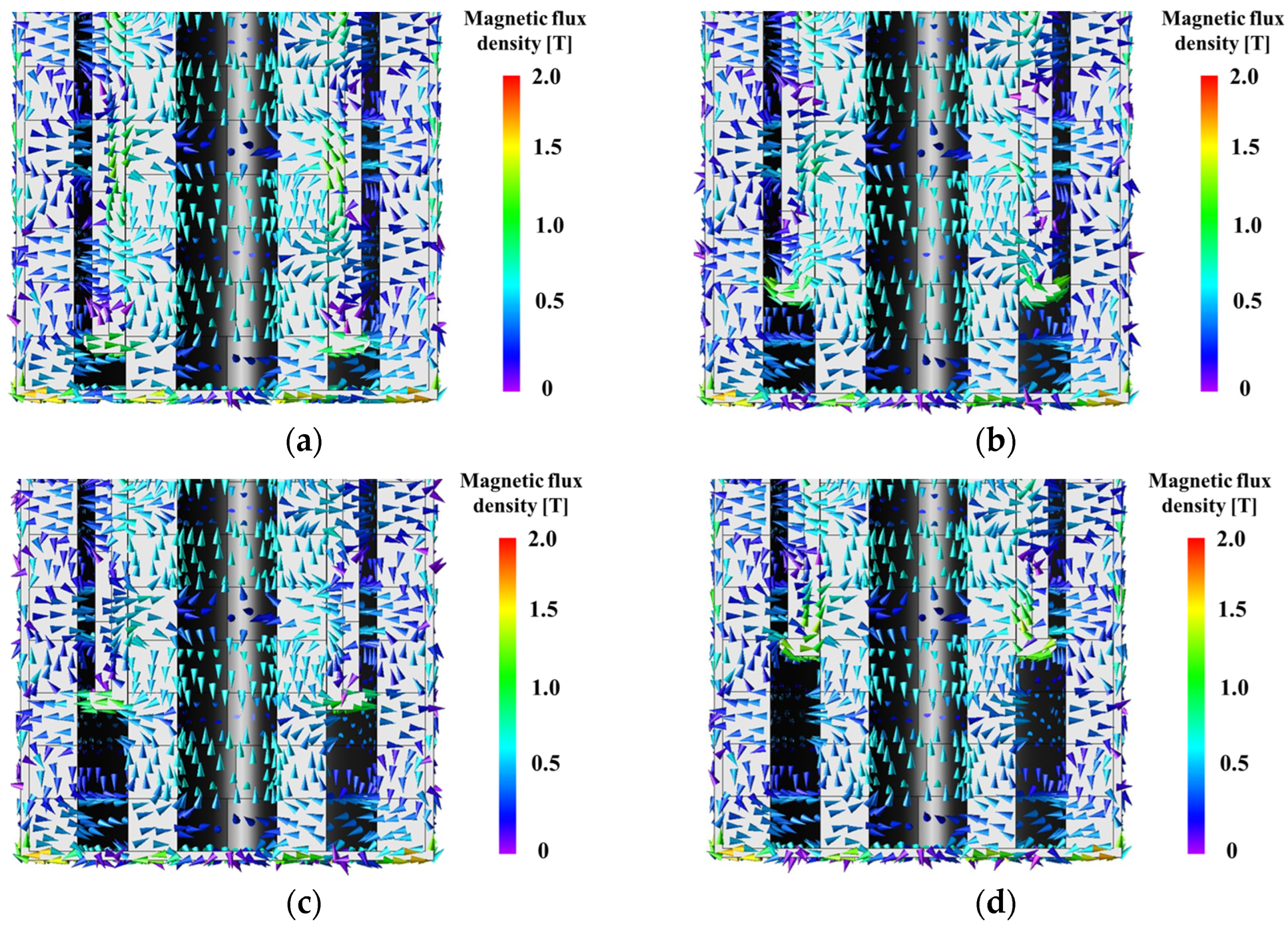
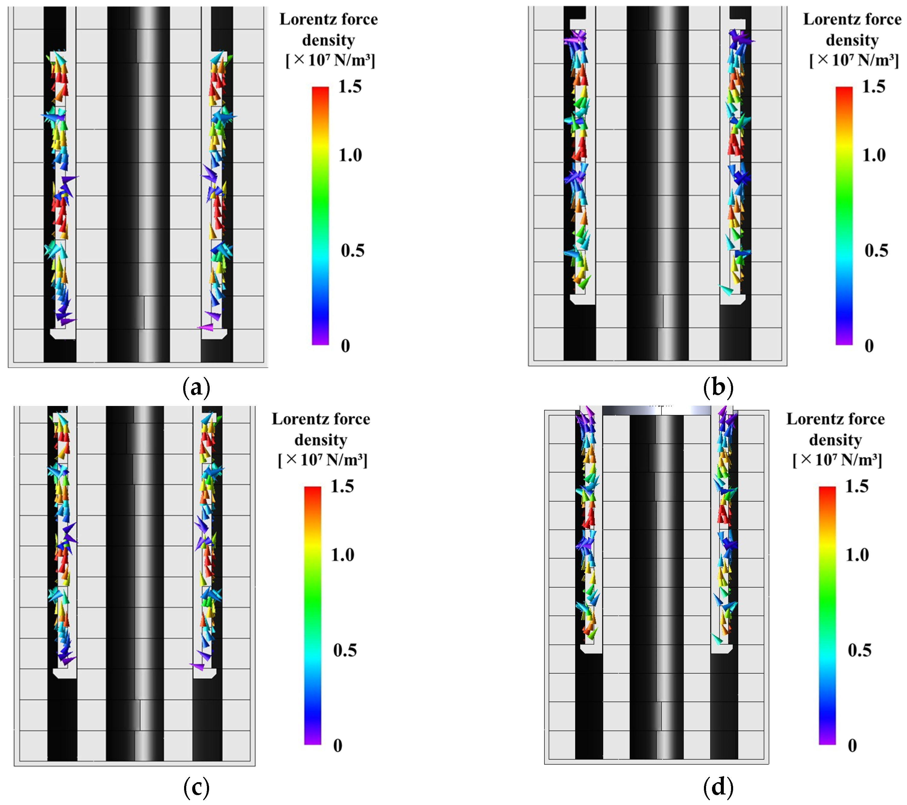
Next, Figure 14a–d display the magnetic-flux-density vectors at Steps 2–5. As in Step 1 corresponding to Figure 13a, even when the electrical angle changes, the flux near the coils remains highly concentrated and oriented perpendicular to the coils. Consequently, effective Lorentz forces are continuously applied to the coils despite phase shifts in the three-phase excitation. Because the flux distribution neither deteriorates nor weakens significantly, relatively constant thrust can be expected throughout the entire stroke. Figure 15a–d show Lorentz-force vector plots for Steps 2–5. Even as the current phase changes, the Lorentz force as a whole maintains the target direction. This is because multiple coils are arranged coaxially, and the three-phase excitation implements in the linear direction an effect analogous to a “rotating magnetic field.” When the current in one coil decays, the current in another coil increases, allowing the total force to remain consistently forward.
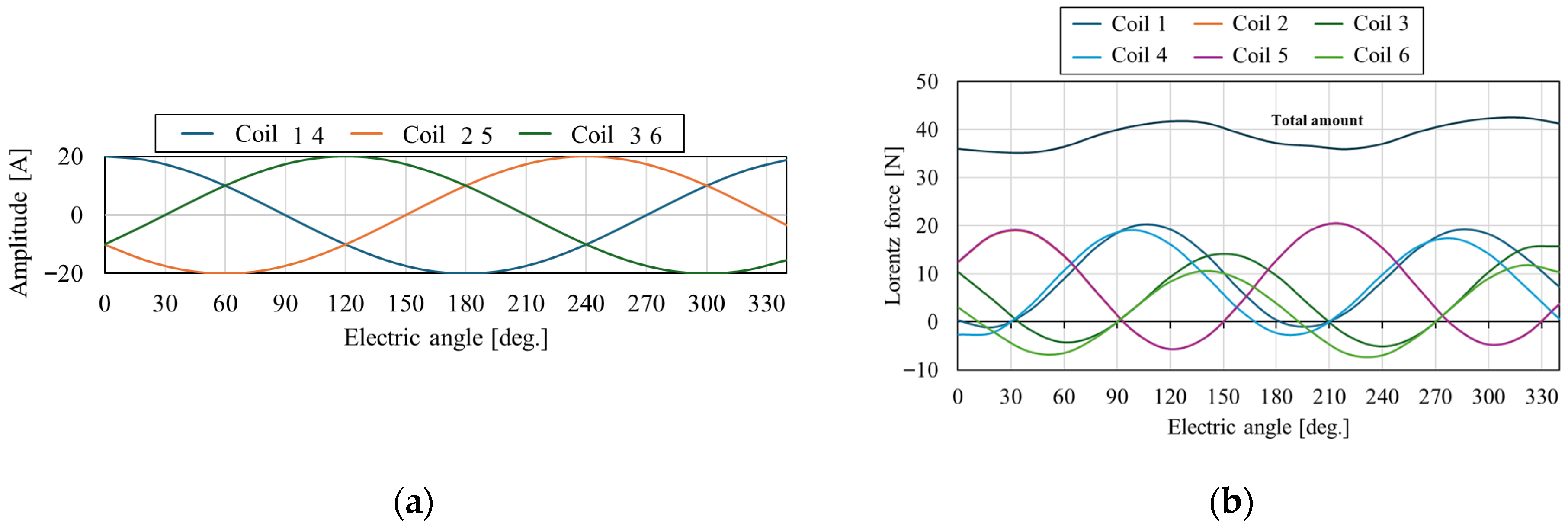
Figure 16a shows the amplitude of the three-phase currents as a function of electrical angle; the vertical axis represents amplitude and the horizontal axis electrical angle. “Coil14” denotes Coils 1 and 4, “Coil25” Coils 2 and 5, and “Coil36” Coils 3 and 6. The three coil sets—Coil14, Coil25, and Coil36—receive currents following standard three-phase sinusoidal waveforms with relative phase offsets. Thus, when the current amplitude in one coil decreases, that in another increases, ensuring continuity of thrust overall. Figure 16b plots the Lorentz force for each coil at the corresponding electrical angles and overlays the total thrust (“Totals”) on the same graph; the vertical axis indicates Lorentz force and the horizontal axis electrical angle. Although the force acts predominantly in the positive direction, some points exhibit negative values. As noted above, these temporary and local phenomena arise from geometric factors such as coil height. Because multiple coils are excited with phase shifts, these negative components do not pose a serious problem for the system as a whole.

4. Thrust Enhancement Analysis by Three-Phase AC Initial Phase Optimization

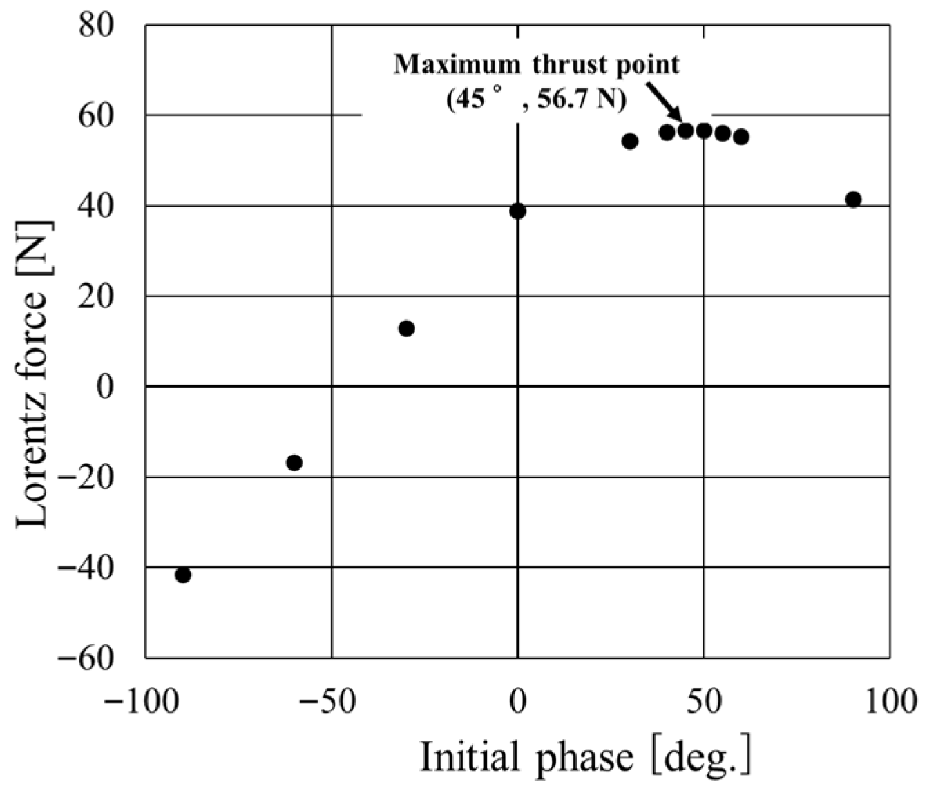
Building on the fundamental behavior established in the previous chapter, this chapter investigates phase optimization under steady operation and—assuming continuous operation with the initial phase of the three-phase excitation held constant—identifies the that maximizes the averaged thrust. The initial phase is maintained during operation. The initial phase of the three-phase currents was scanned from −90° to 90° in 30° increments, and more finely from 40° to 60° in 5° increments; for each phase, the coil currents and resulting Lorentz forces were calculated. As a representative case, the three-phase waveforms for an initial phase of 45° are shown in Figure 17.
Figure 18 plots the average Lorentz force as a function of the initial phase; the vertical axis represents the average Lorentz force and the horizontal axis the initial phase. The analysis confirmed that a maximum thrust of 56.7 N is obtained near an initial phase of 45°. This result demonstrates that by exploiting phase control of the three-phase currents, the optimum phase can be selected continuously or at required timings to extract high thrust under actual operating conditions. When engine valves must be opened and closed rapidly and precisely, this characteristic allows both the securing of sufficient thrust and the fine adjustment of output.
Overall, the present linear-actuator design combines strong magnetic-flux concentration produced by the dual-Halbach array with the stable Lorentz-force generation afforded by phase-controlled three-phase excitation. Although local intervals with reverse forces occur, the “continuous propulsion” effect of the three-phase currents keeps the net thrust directed mainly forward, yielding the maximum value of 56.7 N. This performance exceeds that achievable with simple pole arrangements or single-phase actuators and offers a significant advantage in applications demanding high response and high output, such as engine-valve drives. Moreover, the simulation results indicate that the actuator delivers not only excellent thrust under static or quasi-static conditions. High rotational speeds can be expected in the engine when greater thrust force is used. Because multiple coils cooperate to form a “moving magnetic field,” the design is inherently resistant to large thrust drop-offs associated with position or phase, making it well suited to real-time high-frequency reciprocation and enabling fine valve control in certain engine operating regimes. Further optimization of structural parameters—such as coil height and bobbin geometry—and of detailed phase-control strategies could attenuate negative force components, thereby enhancing average thrust and operating efficiency. For applications like engine-valve actuation, where reliable and continuous control is essential, such refinements are expected to be critical. In summary, concentrated magnetic flux provided by the dual-Halbach array, three-phase excitation, and coordinated multi-coil operation together yielded a maximum thrust of 56.7 N. The results in this chapter are based on quasi-static analysis. The demonstration of dynamic performance (including load systems and drive circuits) is left to future verification.

5. Conclusions

This study was conducted to realize a direct-drive linear actuator that simultaneously satisfies the requirements of high thrust, high responsiveness, and compactness for driving the valves of internal-combustion engines. Because conventional cam mechanisms make optimal valve-lift control difficult under varying rotational speeds and impose mechanical constraints on valve behavior, a compact yet high-thrust linear actuator is indispensable for achieving highly flexible combustion strategies under camless operation. The actuator proposed herein employs the solenoid coil itself as the mover and arranges permanent magnets both inside and outside the coil to form a dual-Halbach array that concentrates the magnetic flux strongly in a single direction. NEOMAX-P11, which offers excellent machinability and shaping freedom, was selected for the magnets, and the high-permeability permalloy YEP-B was used for the yoke and bobbin. Electromagnetic-field analysis with JMAG was performed to evaluate the actuator thrust. The analysis showed that an average thrust of 56.7 N was achieved when the initial phase of the three-phase currents was set to 45°. Phase sweeping over −90° to 90° produced a smooth thrust curve; even when local reverse forces appeared, cooperative excitation of the multiple coils maintained a net positive thrust, confirming a ‘continuous-propulsion’ characteristic. Because the three-phase currents implement in the linear direction an effect analogous to a rotating magnetic field, the magnetic flux and Lorentz force remain homogeneous over the entire stroke, and sharp thrust valleys are unlikely to occur.
Key findings of this study are as follows:
  • Architecture for reciprocating use: We propose a compact voice-coil-motor type linear actuator specifically conceived for reciprocating valve motion, employing inner and outer dual Halbach permanent-magnet arrays to focus flux while preserving a small form factor.
  • Average thrust: Under three-phase excitation, an average thrust of 56.7 N was obtained in the valve-actuation direction.
  • Initial-phase optimization (hardware-invariant): Without altering the hardware (geometry, materials, or the numbers of magnets and coils), varying only the initial phase of the three-phase current increased the cycle-averaged thrust; sweeping the initial phase from minus 90 to 90° (30° steps, refined to 5° the optimum) revealed a maximum average thrust 45°.
  • Continuous propulsion: Despite local reverse components, coordinated excitation of multiple coils maintained a net positive thrust over one electrical cycle.
This combination of high thrust and sustained force generation suggests that rapid and accurate adjustment of valve timing and lift may be achievable even in transient regimes where engine speed changes abruptly. With further development and system-level integration, the approach may contribute to reductions in pumping losses, enable lean-burn operation, and potentially extend to advanced combustion modes such as homogeneous charge compression ignition (HCCI); however, practical deployment is constrained by the electrical power supply, including alternator loading and power-conversion losses. The proposed approach may also benefit medical devices, robotic end-effectors, and precision positioning systems that require large thrust and fast response in confined spaces. The analysis revealed local reverse Lorentz forces attributable to the actuator geometry, indicating that shape optimization is key to further performance improvement. Thermal management will require the design of direct-cooling ducts using coolant water or engine oil, evaluation of material heat resistance, and optimization of the winding fill factor. Real-time phase-control systems could further improve energy efficiency in the high-speed regime.
In summary, by combining a dual-Halbach array with three-phase excitation, this study presents a design guideline that delivers an average thrust exceeding 50 N from a compact device, thereby addressing the previously unresolved issues of insufficient output. Through additional design optimization and experimental validation, the actuator is expected to become a next-generation high-efficiency, high-performance solution for demanding linear-motion applications, including engine-valve drives. The retention of closed valves without power is outside the scope of this study and specific retention mechanisms (springs, magnetic latches, etc.) and their energy balance will be evaluated in future studies. The present conclusions are derived from quasi-static finite-element analysis of the actuator. The dynamic realization of target valve-lift profiles—including interaction with valve-train loads, drive electronics, and control—will be addressed in future studies.

Author Contributions

Conceptualization, J.K.; methodology, J.K. and H.K.; software, J.K., R.O., A.E., and T.N.; validation, D.U., K.O., T.K., K.I., A.E., H.K., and T.N.; formal analysis, D.U., K.O., T.K., and K.I.; investigation, J.K., R.O., T.T., S.K., and I.K.; resources, H.K. and T.N.; data curation, J.K.; writing—original draft preparation, J.K.; writing—review and editing, T.N.; visualization, J.K.; supervision, H.K. and T.N.; project administration, T.N.; funding acquisition, T.N. All authors have read and agreed to the published version of the manuscript.

Funding

This research received no external funding.

Data Availability Statement

The data presented in this study are available on request from the corresponding author.

Conflicts of Interest

The authors declare no conflicts of interest.

References

  1. Shiao, Y.; Kantipudi, M.B.; Weng, C.-B. New actuation control for hybrid electromagnetic valve train. Appl. Sci. 2022, 12, 10449. [Google Scholar] [CrossRef]
  2. Fan, X.; Yin, J.; Lu, Q. Design and analysis of a novel composited electromagnetic linear actuator. Actuators 2022, 11, 6. [Google Scholar] [CrossRef]
  3. Zhao, Y.; Yue, H.; Yang, F.; Zhu, J. A high thrust density voice-coil actuator with a new structure of double magnetic circuits for CubeSat deployers. IEEE Trans. Ind. Electron. 2022, 69, 13305–13315. [Google Scholar] [CrossRef]
  4. Yu, C.; Wu, G.; Wang, Y.; Xiao, Z.; Duan, Y.; Chen, Z. Design of a coaxial integrated macro–micro composite actuator with long stroke and high precision. IEEE Access 2022, 10, 43501–43513. [Google Scholar] [CrossRef]
  5. Saeedi, S.; Sadighi, A. Digital tracking control of a cylindrical voice-coil actuator. In Proceedings of the 2022 10th RSI International Conference on Robotics and Mechatronics (ICRoM), Tehran, Iran, 22–24 November 2022; pp. 291–295. [Google Scholar] [CrossRef]
  6. Shantiaee Zade, S.M.; Robati, M.; Gilani Nejad, M.; Maleki, S.; Sadighi, A. Optimal design and control of a planar voice-coil actuator for micro-positioning applications. In Proceedings of the 2022 10th RSI International Conference on Robotics and Mechatronics (ICRoM), Tehran, Iran, 22–24 November 2022; pp. 439–444. [Google Scholar] [CrossRef]
  7. Lee, C.-P.; Tsai, M.-C.; Fuh, Y.-K. Tiny piezoelectric multi-layered actuators with application in a compact camera module—Design, fabrication, assembling and testing issues. Micromachines 2022, 13, 2126. [Google Scholar] [CrossRef] [PubMed]
  8. Shan, G.; Li, Y.; Zhang, L.; Wang, Z.; Zhang, Y.; Qian, J. Contributed Review: Application of Voice-Coil Motors in High-Precision Positioning Stages with Large Travel Ranges. Rev. Sci. Instrum. 2015, 86, 101501. [Google Scholar] [CrossRef] [PubMed]
  9. Majima, Y.; Kuroda, J.; Suzuki, R.; Narita, T.; Kato, H. Performance improvement of gasoline engines using linear actuator: Fundamental consideration of heat effect on thrust characteristics. Proc. Sch. Eng. Tokai Univ. 2021, 46, 37–42. [Google Scholar] [CrossRef]
  10. Sato, Y.; Narita, T.; Kato, H.; Uchida, H.T.; Matsumura, Y. Valve Mechanism for Gasoline Engine with Linear Motor. Proc. Sch. Eng. Tokai Univ. 2019, 44, 35–39. [Google Scholar] [CrossRef]
  11. Li, B.; Zhang, J.; Zhao, X.; Liu, B.; Dong, H. Research on air-gap magnetic-field characteristics of trapezoidal Halbach permanent-magnet linear synchronous motor based on improved equivalent surface-current method. Energies 2023, 16, 793. [Google Scholar] [CrossRef]
  12. Shen, Y.; Lu, Q.; Li, Y. Design criterion and analysis of hybrid-excited vernier reluctance linear machine with slot Halbach PM arrays. IEEE Trans. Ind. Electron. 2022, 70, 5074–5084. [Google Scholar] [CrossRef]
  13. Xie, Y.; He, S.; Shao, J.; Ye, B.; Yang, F.; Wang, L. Design and research of a dual-rotor consequent-pole vernier motor with Halbach array. IEEE Access 2022, 10, 53918–53927. [Google Scholar] [CrossRef]
  14. Consolo, V.; Musolino, A.; Rizzo, R.; Sani, L. Design of a dual Halbach-array tubular linear motor for long stroke and large force. In Proceedings of the 2020 XXV International Conference on Electrical Machines (ICEM), Gothenburg, Sweden, 23–26 August 2020; pp. 647–653. [Google Scholar] [CrossRef]
  15. Arish, N.; Yaghobi, H. Analysis of a new linear dual-stator consequent-pole Halbach-array flux-reversal machine. Int. J. Eng. 2021, 34, 2002–2009. [Google Scholar] [CrossRef]
  16. Ling, Z.; Ji, J.; Zeng, T.; Zhao, W. Design optimization and comparison of linear magnetic actuators under different topologies. Chin. J. Electr. 2020, 6, 41–51. [Google Scholar] [CrossRef]
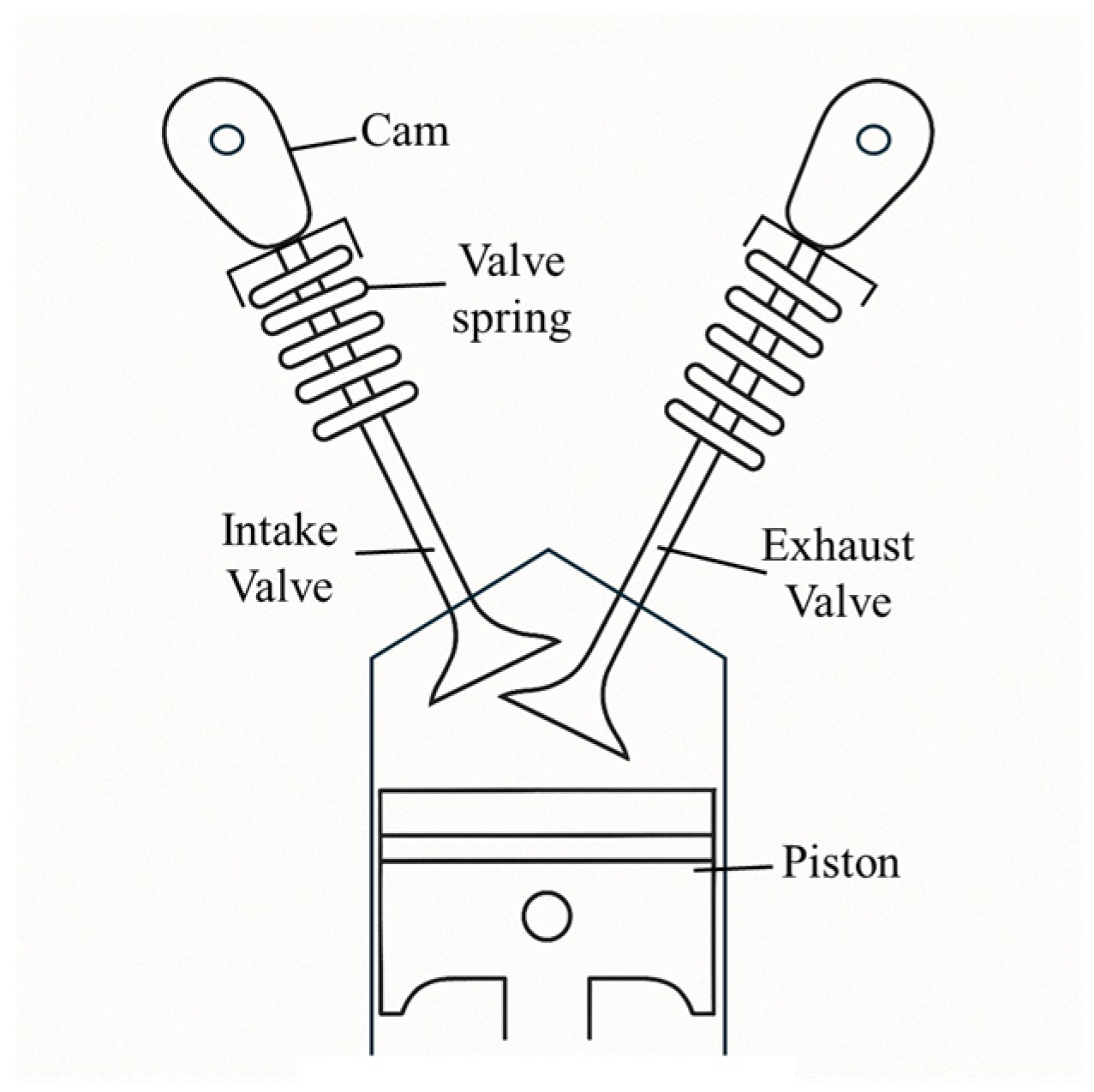
Figure 1. Schematic of a cylinder head of an internal combustion engine.
Actuators 14 00476 g001
Figure 2. Schematic of Halbach and dual Halbach arrays. Red denotes the N pole, blue the S pole; solid lines represent magnetic field lines, and arrows indicate the direction of magnetic flux. (a) Halbach array and its magnetic field; (b) Dual Halbach array and its magnetic field.
Actuators 14 00476 g002
Figure 3. Principle of three-phase alternating current (step 1). (a) A simple cross section of linear motor. Green arrows indicate the magnetic flux direction along the +x direction; pink arrows indicate the magnetic flux direction along the −x direction; blue arrows indicate the direction of the Lorentz force; black arrows indicate the magnetization direction; the numbers indicate the coil numbers; (b) Three-phase alternating current. The solid line shows the waveform of Coil 1, the dashed line shows that of Coil 2, and the dash–dot line shows that of Coil 3.
Actuators 14 00476 g003
Figure 4. Principle of three-phase alternating current (step 2). (a) A simple cross section of linear motor. Green arrows indicate the magnetic flux direction along the +x direction; pink arrows indicate the magnetic flux direction along the −x direction; blue arrows indicate the direction of the Lorentz force; black arrows indicate the magnetization direction; the numbers indicate the coil numbers; (b) Three-phase alternating current. The solid line shows the waveform of Coil 1, the dashed line shows that of Coil 2, and the dash–dot line shows that of Coil 3.
Actuators 14 00476 g004
Figure 5. Principle of three-phase alternating current (step 3). (a) A simple cross section of linear motor. Green arrows indicate the magnetic flux direction along the +x direction; pink arrows indicate the magnetic flux direction along the −x direction; blue arrows indicate the direction of the Lorentz force; black arrows indicate the magnetization direction; the numbers indicate the coil numbers; (b) Three-phase alternating current. The solid line shows the waveform of Coil 1, the dashed line shows that of Coil 2, and the dash–dot line shows that of Coil 3.
Actuators 14 00476 g005
Figure 6. Principle of three-phase alternating current (step 4). (a) A simple cross section of linear motor. Green arrows indicate the magnetic flux direction along the +x direction; pink arrows indicate the magnetic flux direction along the −x direction; blue arrows indicate the direction of the Lorentz force; black arrows indicate the magnetization direction; the numbers indicate the coil numbers; (b) Three-phase alternating current. The solid line shows the waveform of Coil 1, the dashed line shows that of Coil 2, and the dash–dot line shows that of Coil 3.
Actuators 14 00476 g006
Figure 7. Principle of three-phase alternating current (step 5) (a) A simple cross section of linear motor. Green arrows indicate the magnetic flux direction along the +x direction; pink arrows indicate the magnetic flux direction along the −x direction; blue arrows indicate the direction of the Lorentz force; black arrows indicate the magnetization direction; the numbers indicate the coil numbers; (b) Three-phase alternating current. The solid line shows the waveform of Coil 1, the dashed line shows that of Coil 2, and the dash–dot line shows that of Coil 3.
Actuators 14 00476 g007
Figure 8. Analysis model of the proposed actuator. Red denotes the N pole, and blue denotes the S pole.
Actuators 14 00476 g008
Figure 9. Exploded view of the proposed actuator.
Actuators 14 00476 g009
Figure 10. Actuator Components: (a) Case (Stator); (b) Bobbin/Valve (Mover); (c) Coil (Mover); (d) Outer magnet (Stator); (e) Inner magnet (Stator).
Actuators 14 00476 g010
Figure 11. Mesh distribution by component. Solid lines represent the boundaries between the subdivided mesh elements: (a) case; (b) bobbin and valve; (c) coils; (d) outer magnets; (e) inner magnets.
Actuators 14 00476 g011
Figure 12. Magnetization curves of magnetic materials used in the analysis: (a) Magnetization curve of NEOMAX-P11 (Neodymium bonded magnet); (b) Magnetization curve of YEP-B (Permalloy).
Actuators 14 00476 g012
Figure 13. Vector plot of the flux density and the Lorentz force: (a) Vector plot of the magnetic flux density (electric angle of 0°); (b) Vector plot of the Lorentz force generated at the coils (electric angle 0°).
Actuators 14 00476 g013
Figure 14. Vector plot of magnetic flux density at 0 [deg.]: (a) Step 2; (b) Step 3; (c) Step 4; (d) Step 5.
Actuators 14 00476 g014
Figure 15. Vector plot of Lorentz force at 0 [deg.]: (a) Step 2; (b) Step 3; (c) Step 4; (d) Step 5.
Actuators 14 00476 g015
Figure 16. Lorentz force analysis results: (a) Amplitude of the three phase AC in each electric angle; (b) Lorentz force generated in the coils in each electric angle.
Actuators 14 00476 g016
Figure 17. Three-phase alternating current waveform when the initial phase is 45°.
Actuators 14 00476 g017
Figure 18. Relationship between the initial phase of the three phase AC and generated Lorentz force.
Actuators 14 00476 g018
Disclaimer/Publisher’s Note: The statements, opinions and data contained in all publications are solely those of the individual author(s) and contributor(s) and not of MDPI and/or the editor(s). MDPI and/or the editor(s) disclaim responsibility for any injury to people or property resulting from any ideas, methods, instructions or products referred to in the content.