1. Introduction
Heat exchangers play a crucial role in various sectors including chemical engineering, automotive, food, and many others [
1,
2,
3]. they facilitate processes such as heat transfer, temperature regulation, and energy efficiency enhancement. Fin and tube heat exchangers are one of the most common types of compact heat exchangers [
4]. Many factors influence the performance of heat exchangers [
5,
6,
7,
8]. The flow distribution characteristics of gas–liquid two-phase fluid within the plates under various operating conditions are crucial factors influencing the performance of heat exchangers [
9]. The flow distribution characteristics of heat exchangers include flow distribution, pressure loss, temperature distribution, and so on. In the study of heat exchanger performance, research methods typically include physical experiments and numerical simulations. Mehrpooya M et al. [
10,
11] employed numerical simulation methods to model and analyze various types of heat exchangers, investigating their heat transfer performance under different structural configurations and operating conditions. Mehdi M et al. [
12]. performed a three-dimensional CFD numerical simulation of a coaxial borehole heat exchanger and determined the optimal operating conditions for the heat exchanger. Their findings offer valuable insights for optimizing heat exchanger design. Many researchers have also conducted experimental studies on the heat exchange performance of various types of heat exchangers. Li Jun et al. [
8] studied the influence of flow distribution deviation and nonuniformity on heat transfer performance and outlet temperature distribution by controlling flow rate, and the results show that the heat exchanger has the best performance under uniform inlet flow. Wei chao Lao et al. [
13] conducted experimental studies on the flow boiling of refrigerant R134a in a plate heat exchanger with certain temperatures, pressures, and mass flow rates while also analyzing the effects of vapor quality and mass flux on the variation of heat transfer coefficient (HTC). Burak Markal et al. [
14] studied the effect of inlet temperature on flow boiling behavior of expanding micro-pin-fin type heat sinks under a certain flow rate, and it was concluded that inlet temperature is an influential parameter for thermal characteristics, as are pressure drop values. From the previous references, it can be seen that scholars pay special attention to the parameters of flow, temperature, and pressure when studying the boiling flow characteristics of heat exchangers. These parameters directly influence the heat transfer mechanism, flow regime, system stability, and boiling efficiency. A systematic study of these parameters facilitates a better understanding and optimization of the boiling process, improves heat exchange efficiency, and reduces energy waste. Tahseen et al. [
15]. believe that flow is an extremely important parameter that can affect the heat transfer coefficient and pressure drop of a heat exchanger. Flow rate directly impacts heat transfer efficiency, system stability, and safety, so flow control is critical in flow boiling experimental systems. Real-time flow control can track changes in operating conditions, preventing issues such as equipment overheating and bubble dry-out. Therefore, it is very important to develop a flow boiling experimental system with adaptive flow control. The system encompasses the measurement of system temperature, pressure, and flow rate, along with the adaptive control of pipeline flow and heating power.
To control the flow, many researchers have conducted studies in this area. Yunbin Cheng [
16] designed a PID controller for the water circulation system in a dynamic flow detection device. Experimental results demonstrated that the control system effectively enhanced the stability of the water circulation system’s flow rate. Qixing Liu [
17] proposed an expert PID control algorithm for flow control systems, and simulation results indicated that the algorithm enhanced control accuracy and dynamic performance. E. B. Priyanka et al. [
18] devised a fuzzy PID controller designed to automate oil pipeline systems. Experimental results demonstrated that the controller maintained flow within a specified range while achieving optimal performance and minimal time delay.
In summary, previous studies have primarily focused on the effects of flow, temperature, and pressure on heat exchanger performance; however, several research gaps remain, which this study aims to address:
Although PID, fuzzy PID, and expert PID controllers are widely used for flow control, they struggle to maintain optimal performance under the varying operating conditions of this experimental system. Traditional PID requires manual parameter tuning, which can result in instability and inefficiency as operating conditions change. Although fuzzy PID and expert PID methods offer greater flexibility, they still demand significant expertise for tuning and are sensitive to external disturbances, limiting their practical application in dynamic flow boiling experimental systems. In addition to this, the flow boiling experimental system lacks real-time and adaptive control, as most studies focus on the flow boiling characteristics of plate heat exchangers, with limited attention to the development of adaptive control systems. Real-time adaptive control is essential for maintaining optimal performance and preventing issues such as overheating or bubble drying, which directly impact the system’s efficiency and safety. Absence of Effective Control Solutions for Variable Operating Conditions: Existing flow control methods often fail to provide adequate real-time adjustments to changes in load and operating conditions. As a result, maintaining consistent and reliable performance in flow boiling experimental systems remains a challenge.
Novelty of This Research: Introduction of WOA-Improved Single-Neuron PID Adaptive Control: This study introduces a novel whale optimization algorithm (WOA)-improved single-neuron PID adaptive control system. Unlike traditional PID or fuzzy PID controllers, this method allows for more efficient parameter tuning without the need for manual adjustments, making it suitable for flow boiling systems that experience varying operating conditions.
Adaptive Control for Flow Boiling Experimental Systems: The proposed control system is specifically designed to enhance the performance of flow boiling experimental systems. By implementing real-time adaptive control, this research ensures that flow can be adjusted automatically, thus improving the system’s ability to handle dynamic conditions. By addressing these gaps, this research provides a more adaptive flow control solution for flow boiling experimental systems.
The following are the novelties of this paper:
A single-neuron PID adaptive control algorithm optimized by the whale optimization algorithm (WOA) is proposed for the flow control of the flow boiling experimental system. The algorithm optimizes the scaling factor through WOA, overcomes the defect of traditional PID requiring manual parameter adjustment, and significantly improves the response speed and robustness of the system.
In order to solve the problem that the parameters of the flow rates model fluctuate due to the change in operating conditions, this paper combines the RLS method for online identification. This method improves the accuracy of model identification and enables the control algorithm to dynamically adapt to the changes of the flow model.
2. System Design
Our research focuses on developing an experimental system for flow boiling that incorporates adaptive control ability. The experimental system requires to measure pressure, temperature, and flow. Given that the refrigerant must enter the heat exchange plate with a specific dryness, it is essential to regulate the flow and temperature within the system. The system’s experimental temperature is controlled by the heating power, the flow rate is regulated by the motor speed, and the pressure is influenced by the quality of the injected refrigerant, heating power, and flow rate.
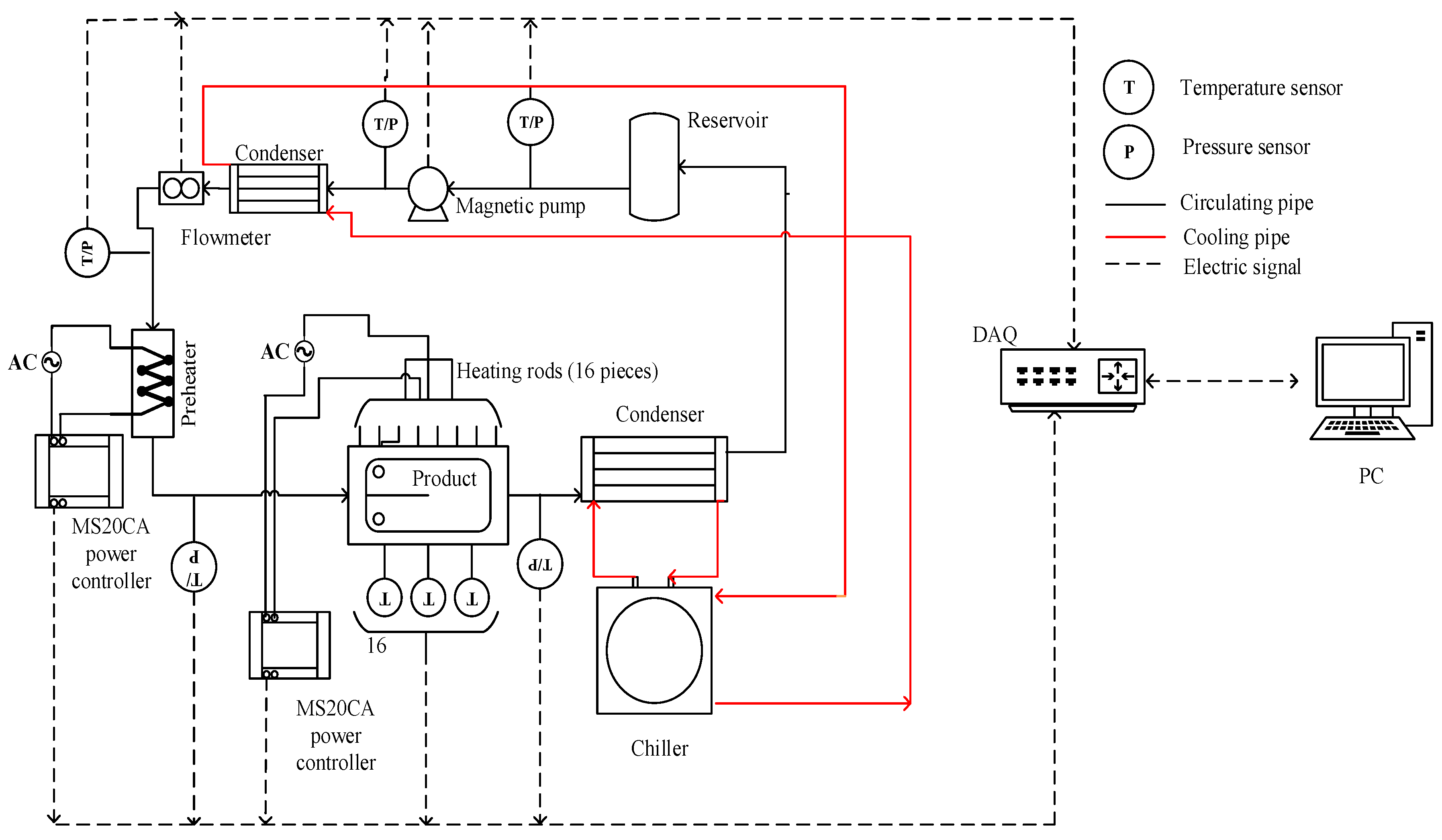
The experimental system comprises a computer (Savior y7000, Lenovo, Beijing, China), data acquisition cards (I-7017, Hongge Technology Co., Ltd., Shanghai, China), flow meter (DMF-1, Zhongxing Bona automation equipment Co., Ltd., Xian, China), reservoir (Make by oneself), temperature sensors (thermocouple and PT100) (K type thermocoupleand PT100, Jiumao Automation (Dalian) Co., Ltd., Dalian, China), pressure sensors (JM-801, Anhui Jiamin instrument Co., Ltd., Anhui, China), preheater (Make by oneself), heating rods (Make by oneself), MS20CA power controllers (MS20CA, Zibo Silicon Microelectronics Technology Co., Ltd., Zibo, China), gear magnetic pump (CS.Y015, Shenzhen Weikeda precision Technology Co., Ltd., Shenzhen, China), product (fins) (Make by oneself), condensers (Make by oneself), and chiller (DHF-50/80,Shanghai Sinovac Instrument Co., Ltd., Shanghai, China). The schematic diagram of the system is illustrated in
Figure 1. The entire experimental setup constitutes a cyclic system. At the onset of the experiment, refrigerant is injected into the reservoir, then the magnetic pump propels the refrigerant to flow through the pipeline. The condenser transforms the refrigerant from a gas state to a gas–liquid two-phase state. Then, the refrigerant flows through the flowmeter. The flowmeter is responsible for measuring the flow of refrigerant in the pipeline. Then, the refrigerant flows through the preheater and enters the product. Finally, the refrigerant passes through the second condenser and returns to the reservoir to form a cycle.
The chiller and the condenser form a cooling cycle, primarily tasked with reducing the temperature of the refrigerant within the experimental loop. The temperature sensor is used to measure the fluid temperature in each section of the pipeline, as well as the temperature of the experimental product. Likewise, the pressure sensor is utilized to measure the pressure of each section of the pipeline. The data acquisition card transmits the data collected by the sensors to the computer. The experimental conditions are established based on the measured temperature, pressure, and flow. With stable power output from the preheater and heating rod, the flow rate of the refrigerant at the inlet of the experimental section is regulated by adjusting the motor speed. This adjustment ensures that the refrigerant enters the product at the desired dryness level.
Table 1 lists the technical specifications for key components.
3. System Flow Rates Model Identification
In order to understand the dynamic characteristics of the system flow rates, design a more effective controller, and optimize the system performance, it is necessary to identify and simulate the control system. Typically, mathematical models can be established using theoretical analysis or experimental methods [
19]. In this paper, the experimental modeling method is used. During the offline identification process of the system, the heating is turned off, and the system heating is considered as noise when designing the flow adaptive controller.
The system flow rates model is solved through offline identification. A step signal is used as the identification signal, with the servo motor controlling the system flow rates by adjusting its speed. During the identification process, it was observed that various factors, such as the refrigerant quality, coolant flow rate, and type of refrigerant, could result in different flow rates at the same motor speed. From the above description, the output of the system (i.e., flow rate) is influenced not only by the current input (servo motor speed) but also by the system’s inherent characteristics and external factors, such as refrigerant quality, coolant flow rate, and refrigerant quality.
It is a common system identification method to use a step signal as the system input for model identification [
20]. Sharma et al. [
21] proposed using step input to identify continuous-time systems with dead time. This method can estimate the model parameters more accurately. Dazi Li et al. [
22]. presented a three-step closed-loop identification method based on step response and open-loop transformation. This proposed method avoids the complexity of direct closed-loop identification and enhances the results and accuracy of identification for continuous systems with large time delays. Yongli Zhang et al. [
23] identified the experimental platform of a resonant system using the step response system identification method, and the results indicate that the identified model fits well. The previous literature indicates that a step signal can be used to identify continuous-time systems with dead time and delays. In practical applications, most systems are of this type, including the system identified in this paper. Therefore, this paper employs a step signal for system identification. To determine the appropriate sampling frequency, data were collected at a higher sampling rate and analyzed using Fourier transformation, revealing that most of the system’s spectral components are below 0.5 Hz. The system’s traffic is sampled every 1 s until it reaches a steady state, after which the data is imported into the MATLAB System Identification Toolbox for offline identification. Due to the ambiguous order of the system, the primary models utilized in practical applications are first-, second-, and third-order models. Therefore, this paper primarily identifies these three models, compares their fit, and conducts a comprehensive analysis to select the best model.
The main operating range for this system is 800 rpm to 2500 rpm. To identify the system, flow response data were collected at motor speeds of 1000 rpm, 1500 rpm, and 2000 rpm, under conditions characterized by a coolant temperature of −10 °C, a coolant speed duty cycle of 80%, a refrigerant mass of 1.8 kg, and an initial pressure of 370 kPa.
Table 2 shows the corresponding experimental conditions.
From (a) in
Figure 2, it is evident that the steady-state value of the system flow increases with motor speed. The system exhibits an overshoot in response to the step signal, indicating oscillatory characteristics, which suggests that the system model is at least a second-order system [
24]. Furthermore, the repeated experiment with a motor speed of 2000 rpm in (a) of
Figure 2 demonstrates that the system operates stably.
The flow data identification model at a motor speed of 1000 rpm was utilized, while the flow data at 1500 rpm and 2000 rpm were employed to validate the model. The model fitness [
25] was employed to evaluate the identification results. A higher model fitness value indicates better performance of the identification system, approaching the actual system.
From the results of the identification in (b) of
Figure 2, it is evident that the models P1 (first-order without delay), P1D (first-order with delay), P2 (second-order without zero point and delay), P2D (second-order without zero point but delay), P2DZ (second-order with one zero point and delay), and ARX1 (linear regression equation) demonstrate higher fitness, all exceeding 80%. From the verification set presented in (c) and (d) of
Figure 2, it can be observed that the model fitness of P1, P1D, P2, P2D, P2D, and ARX1 under the data at 1500 rpm remains relatively consistent, all exceeding 70%. However, the fitness of P1, P1D, P2, P2D, and ARX1 models under the data at 2000 rpm is notably reduced to less than 60%, whereas P2DZ remains above 70%. Thus, it can be concluded that the P2DZ model, which includes two poles and one zero point with delay, performs the best. The identified model is as follows:
s is a complex variable, a variable of the Laplace transform. e(−2s) represents the dynamic behavior of a pure delay (or pure lag). The linear dynamic response of the system to the input is represented as 0.09654 s, and is related to the rate of change in the input signal. The constant term 0.009529 usually represents the static gain of the system, that is, the steady-state value of the system output when there is no dynamic change in the input. It relate to the initial flow rates of the system. The quadratic term 111.4s2 indicates that the system is a second-order system, usually with inertial or lagging behavior. This kind of behavior is often encountered in motor control systems, especially when the system has mechanical delays or inertia. The value 71.11 s is related to the damping characteristics of the system. The smaller the damping, the more likely the system is to oscillate. The denominator constant term is set to 1 to standardize the transfer function. e(−2s) indicates that the input signal of the system begins to affect the system after 2 s.
In practical applications, the system transfer function in the s-domain should be discretized [
26]. The z-transform results are as follows:
u(k − 1) represents the previous system input, u(k − 2) represents the input from two steps ago, u(k − 3) represents the input from three steps ago, y(k − 1) represents the previous system output, and y(k − 2) represents the output from two steps ago. From the discretization formula, it is evident that the current system output is influenced by the inputs of the first three. This delay indicates that the system’s response to the input signal exhibits a certain historical dependence. Furthermore, the system’s output also depends on the outputs from the previous moment and the two preceding moments, suggesting the presence of a feedback effect. Notably, the current output is most influenced by the previous output.
When factors such as the quantity of refrigerant introduced into the system change, the flow model of the system may also be affected. To verify the variation of the flow rates model under different working conditions, flow data of the system were collected under the conditions of
Table 2 when the input signal of the system was set to 1000 rpm. Coolant temperature and coolant speed duty cycle are properties of the cooling system that influence the pressure, flow, and temperature within the circulating system. Refrigerant mass is a characteristic of the circulatory system that affects both the pressure and flow in the system.
From
Figure 3, it is evident that the steady-state value of the system flow is influenced by factors such as refrigerant quality. Changes in refrigerant mass may cause the transfer function to change. This varying property complicates accurate modeling of the system using a transfer function with fixed parameters, necessitating the use of adaptive control or online adjustment control strategies. The model identified under case 2 is as follows:
Equation (3) represents the relationship between the input speed and the output flow rate. Upon comparing Equations (1) and (3), it becomes evident that the coefficients of the system model vary under different conditions. These variations suggest that a fixed control strategy may not be adequate to maintain optimal performance across all operating scenarios. Therefore, an adaptive control strategy, which dynamically adjusts the control parameters based on real-time feedback, is essential.
4. WOA Improved Single Neuron PID Control Algorithm
Due to the variation in system model parameters with changing conditions, an adaptive algorithm is necessary to control the system flow. The single-neuron PID [
27] serves as an adaptive control algorithm. This paper employs an incremental PID combined with a single neuron to enhance control performance.
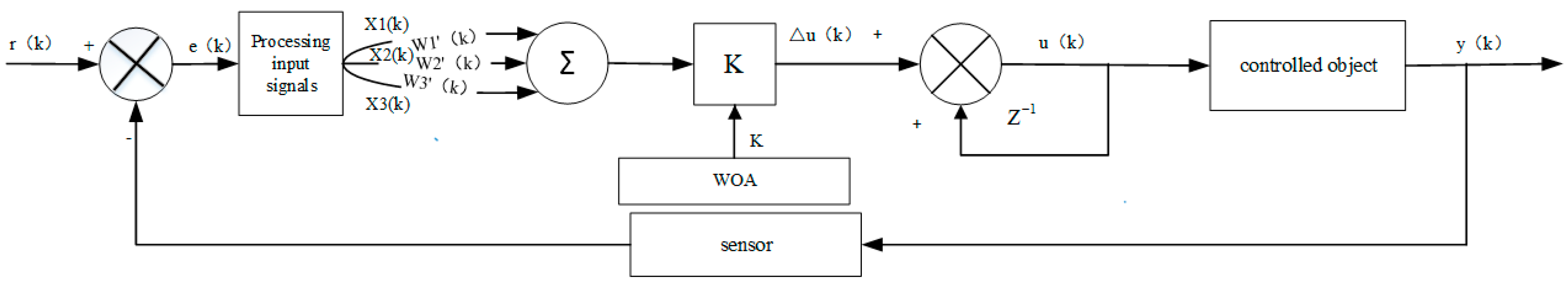
The control model of the single-neuron PID is depicted in
Figure 4, where
r(
k) represents the set flow (expected value) and
e(
k) denotes the difference between the expected value and the output value of the device
w1′(
k),
w2′(
k), and
w3′(
k) denote the connection weights of the single neuron, while k represents the gain of the system output variable. Δ
u(
k) stands for the input increment of the controlled object,
u(
k) represents the total input of the controlled object,
Z−1 signifies the system delay,
y(
k) denotes the output of the controlled system, and
e(
k) is processed to obtain
x1(
k),
x2(
k), and
x3(
k). These are expressed as:
In numerous practical applications, engineers have observed that the online adjustment of weights is primarily associated with e(k) and e(k − 1).
Therefore, the weight formula is expressed as follows:
At this time, the input control of the controlled system can be written as follows:
In a single-neuron PID controller, the scale factor K is a crucial parameter that determines the relationship between the neuron output and input. The scale factor K is closely linked to the dynamic characteristics, error margin, expected control response, and external interference of the system. If the system’s dynamic response is slow, a larger k value may be necessary to enhance the response speed. Conversely, for systems with a fast dynamic response, a smaller k value can help prevent overly aggressive control. By adjusting the k value through an optimization algorithm, the controller’s performance can be significantly improved, allowing the system to maintain good response characteristics under complex working conditions. This paper optimizes this value using the WOA.
The WOA [
28] is a novel heuristic optimization approach inspired by the hunting tactics of humpback whales. The WOA mimics the predatory behaviors of whales, which can be categorized into three main strategies: Surrounding Predation, Bubble Net Attack, and Search for Prey. The WOA algorithm used in this paper comes from the literature [
29]. Through comparing the optimization results of the WOA and the Particle Swarm Optimization (PSO) algorithm for one-dimensional functions, it is observed that the convergence speed of the WOA surpasses that of PSO. The WOA reaches the optimal value within 5 iterations, whereas PSO requires 10 iterations. These results suggest that WOA exhibits superior optimization ability compared to PSO.
In the controller designed in this article, ITAE [
30] is chosen as the fitness function of the WOA algorithm. ITAE not only indicates the magnitude of the error (control accuracy) but also reflects the speed of error. To ensure that the ITAE fitness function of the WOA algorithm places greater emphasis on system overshoot, an overshoot penalty term is introduced when overshoot occurs. The updated fitness function is provided in Equation (10).
To improve the accuracy of approximating the real system when using the whale optimization algorithm for optimization, the Recursive Least Squares [
31] method is employed to perform online identification of the flow rate model. To evaluate the accuracy of the Recursive Least Squares (RLS) method, simulation identification is performed on the aforementioned Equation (2). The true values of a1, a2, b1, b2, and b3 are 1.259, −0.2788, 0.001072, −0.0008663, and −0.000013. And with approximately 500 iterations, the estimated values of a1, a2, b1, b2, and b3 are 1.258644, −0.278447, 0.001071, −0.0008663, and −0.00001362; the estimated values closely approximate the true values. It is evident that the RLS method exhibits strong identification capability. Considering the variability of the flow model coefficients under different working conditions, Equation (1) is used as the initial system during online identification. When the actual output of the system deviates from the output of the identification model beyond a certain threshold, the RLS method is employed to conduct the online identification process and obtain new model parameters.
The combination of a single-neuron PID and the whale optimization algorithm is shown in
Figure 5. The parameter changes of the system flow rates model are primarily attributed to variations in the system itself, such as the quality of the refrigerant injected into the system and the system’s heating power. Based on the above analysis, before starting single-neuron PID control, only one run of RLS is needed to identify the flow model of the current experimental system and one run of the WOA optimization algorithm to find the optimal scale factor K of the current model. This scale factor will be used continuously in subsequent control. When the output error between the identification system and the actual system exceeds 10%, the RLS and WOA methods should be reactivated for optimization.
5. Results
To assess the feasibility and positional tracking capability of the enhanced whale-optimization-based single-neuron PID control algorithm, simulations are conducted against the standard PID algorithm, the WOA-improved single-neuron PID controller, and the fuzzy PID control algorithm. All simulations are conducted on LabVIEW.
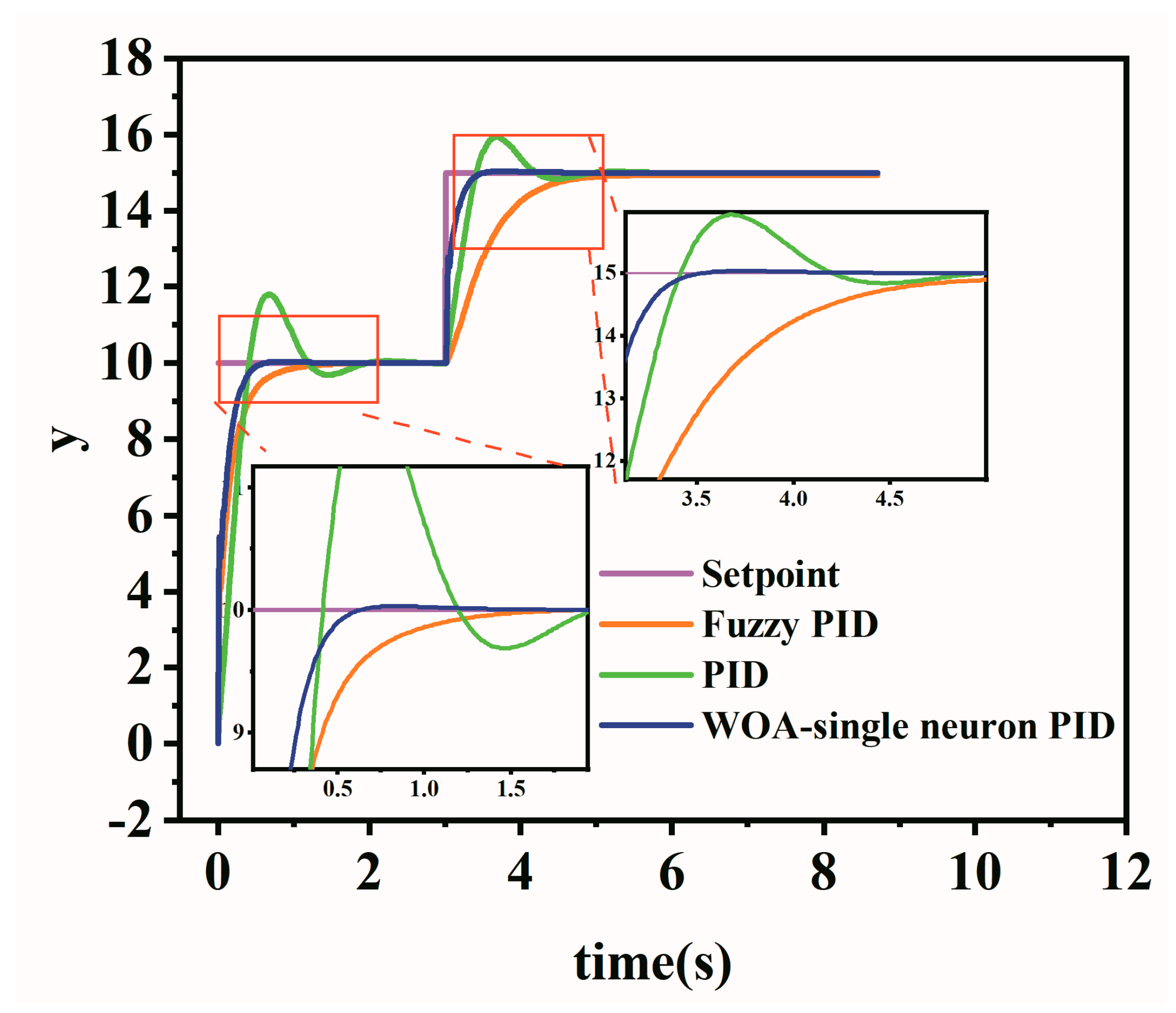
The simulation system employs the model described by Equation (2). The resulting step response and sine signal response are shown in
Figure 6 and
Figure 7. In the step response, the initial step value is 10, and the step value transitions to 15 at t = 3 s. In the sine signal response, the sinusoidal signal frequency is 3, the amplitude is 2, and the offset is 2.
From the
Figure 6, it is apparent that the conventional PID control curve demonstrates considerable overshoot and requires a longer time to achieve a steady state; the initial overshoot reaches 18.01%, and the initial adjustment time needs 1.69 s. Although the fuzzy PID has no overshoot, its adjustment time is longer, reaching 0.88 s. In contrast, the WOA-improved single-neuron PID significantly mitigates the overshoot, with a mere 0.31% overshoot observed, marking a reduction of 98.27% compared to the traditional PID control. The adjustment time is 0.45 s, presenting a reduction of 48.86% compared to that of the fuzzy PID control method. In the system’s steady state, when the step value changes, the traditional PID control curve still exhibits overshoot, with the overshoot peaking at 6.21%, the adjustment time is recorded at 1.04 s. The fuzzy PID method similarly demonstrates no overshoot, with a longer adjustment time, extending to 1.42 s. In contrast, the WOA-improved single-neuron PID showcases a minimal overshoot of only 0.22%, marking a reduction of 96.46% compared to the traditional PID control. Additionally, the adjustment time is 0.32 s, representing a reduction of 69.23% compared to PID. The Y-axis represents the constants.
It can be seen from the sine signal response diagram that the traditional PID parameters can achieve better results after adjustment. However, the traditional PID control curve cannot accurately fit the sinusoidal signal, and there is a phenomenon of tracking ahead. The fuzzy rules of fuzzy PID are taken from the literature [
32]. The output curve of the WOA-improved single-neuron PID is closer to the sinusoidal signal. Upon comparison of the tracking absolute error curves, it is evident that the tracking absolute error of the WOA-improved single-neuron PID is markedly smaller than that of the traditional PID and fuzzy PID methods. The average absolute error [
33] for the traditional PID stands at 0.209, while that for the fuzzy PID is 0.296. In contrast, the average absolute error for the WOA-improved single-neuron PID is 0.120, representing a 45.58% reduction compared to the traditional PID. This underscores the superior position tracking effectiveness of the improved single-neuron PID based on WOA among the three algorithms.
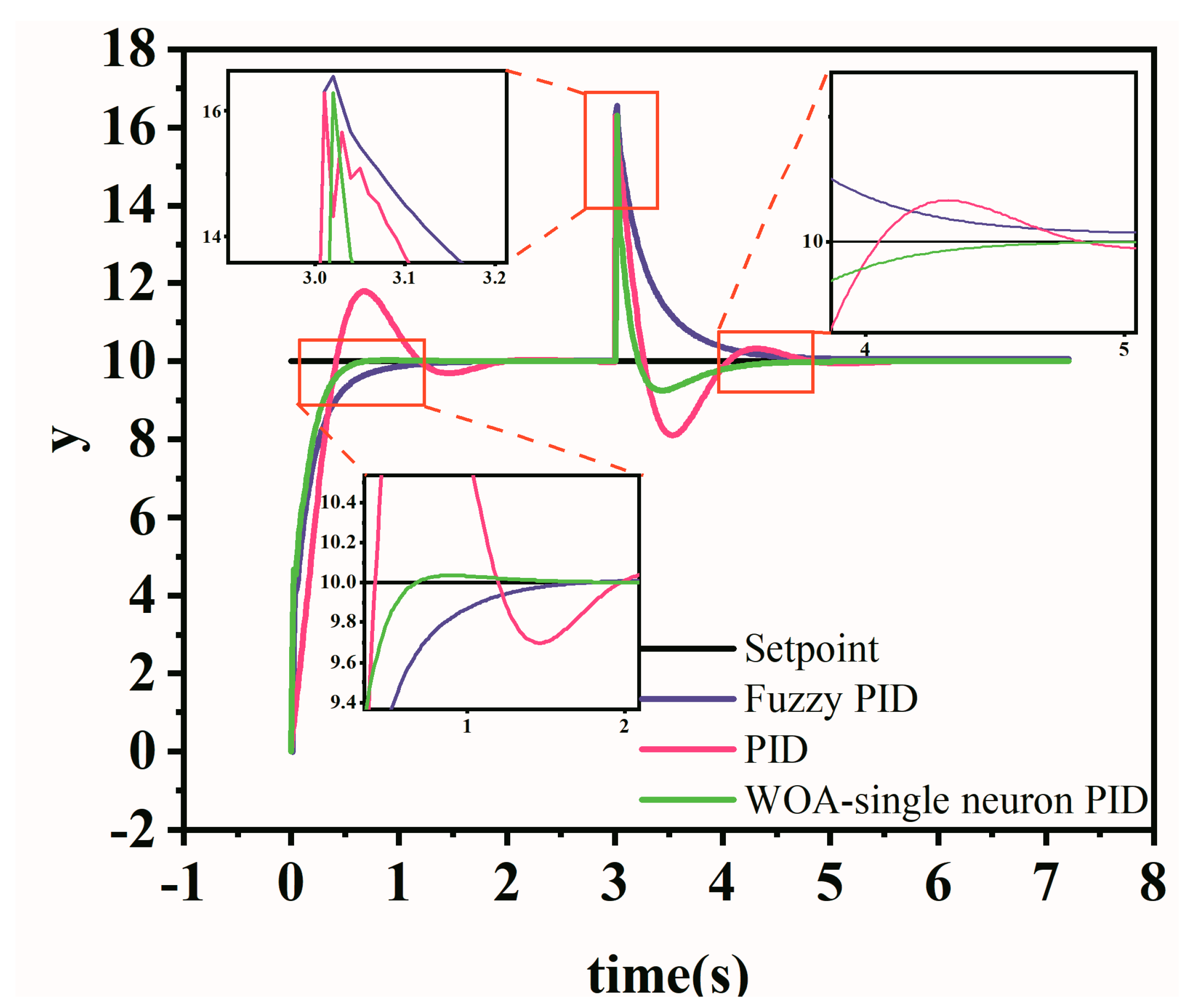
To ascertain the resilience of the WOA-improved single-neuron PID against external interference, an instantaneous disturbance with an amplitude of 5 is introduced to the system output when it is in a stable state [
34]. The step response of the three control algorithms to this external interference is illustrated in
Figure 8. The Y-axis represents the constants. From
Figure 8, it is evident that the WOA-improved single-neuron PID exhibits the highest resilience against external interference. The traditional PID requires 2.46 s to return to a stable state, while the fuzzy PID necessitates 1.28 s. In comparison, the WOA-improved single-neuron PID demonstrates the swiftest recovery to a stable state, taking only 1.01 s. This represents a 1.45 s improvement over the traditional PID and a 0.27 s enhancement over the fuzzy PID.
The online identification simulation results of the system are presented in
Figure 9. As illustrated, when the parameters of the original system model change, the model identified by the algorithm can rapidly adapt to fit the system.
In order to verify the effectiveness and reliability of the RLS method and the WOA-improved single-neuron PID control algorithm in the flow boiling experimental system, the experiment was carried out in the flow boiling experimental system.
Figure 10 is a physical diagram of the entire system.
In order to verify the effectiveness and reliability of the RLS method and the WOA-improved single-neuron PID control algorithm in the flow boiling experimental system, the experiment was carried out in the flow boiling experimental system.
Figure 10 is a physical diagram of the entire system. The step response of identification system and actual system are as
Figure 11. When the experimental refrigerant volume changes from 1.8 kg to 1.7 kg and the coolant temperature changes from −10 °C to −9 °C, we conducted online identification of the traffic model. The initialization values of a1, a2, b1, b2, and b3 are 1.259, −0.2788, 0.001072, −0.0008663, and −0.000013. After online identification, a1, a2, b1, b2, and b3 are 1.084, −0.2504, 0.003644, −0.0032430, and 0.001175. The step response of the identified model is presented in
Figure 11a. It can be seen that when the working conditions change, the system model identified by the RLS method is in good agreement with the actual system. The error at each sampling point is basically within 10%, and the maximum is 8%. The final stable value tends to be consistent, and the steady-state error between the identification system and the actual system is within 5%. Therefore, it is feasible to use the RLS method in this system.
To validate the efficacy of the control algorithms in the flow boiling experimental system, flow data is collected upon issuing control signals, with an acquisition interval of 1 s. The control strategies employed include PID, single-neuron PID, and the WOA-improved single-neuron PID. PID parameters are determined using the empirical trial-and-error method. The control parameters of the single-neuron PID are derived from the previous experiment.
The flow control outcomes are presented in (b) of
Figure 11.
Table 3 presents the performance of the three control algorithms. The table and figure demonstrates that the WOA-improved single-neuron PID algorithm outperforms traditional PID and single-neuron PID algorithms across multiple performance metrics. In terms of dynamic response, the WOA-improved single-neuron PID achieves the shortest rise time of 29 s, significantly faster than the 40 s of single-neuron PID and the 78 s of traditional PID. This indicates that the WOA-improved single-neuron PID enables the system to reach the target value more quickly, thereby reducing the time required for startup or adjustments in practical applications.
Regarding adjustment time, the WOA-improved single-neuron PID exhibits superior performance, with an adjustment time of only 38 s, compared to 63 s for single-neuron PID and 110 s for traditional PID. This highlights the effectiveness of incorporating the WOA-improved single-neuron PID in improving the system’s adaptability, enabling it to stabilize faster after disturbances or initial changes while minimizing overshoot and oscillations.
The steady-state average flow achieved by the WOA-improved single-neuron PID is 9.9848, which is closer to the target value compared to 9.9799 for single-neuron PID and 9.9659 for traditional PID. Additionally, the WOA-improved single-neuron PID achieves the lowest standard error of 0.091439, outperforming the 0.109586 of single-neuron PID and the 0.126469 of traditional PID. This reflects the ability of the WOA-improved single-neuron PID to maintain higher stability and precision during long-term operation, effectively reducing fluctuations and errors.
6. Discussion
In this paper, the WOA-improved single-neuron PID algorithm is integrated with the Recursive Least Squares algorithm (RLS) to establish a robust adaptive control framework. The findings of this study demonstrate the significant advantages of the WOA-improved single-neuron PID algorithm in addressing flow control challenges in flow boiling experimental systems. The proposed approach demonstrates substantial improvements over traditional PID and fuzzy PID controllers. The simulation and experimental results reveal significant reductions in overshoot, adjustment time, and steady-state error achieved by the WOA-improved single-neuron PID algorithm. Traditional PID relies on fixed parameters and manual adjustment. Similarly, fuzzy PID, though more flexible, requires domain-specific expertise and struggles with parameter adaptation under varying conditions. The WOA-improved single-neuron PID algorithm effectively adapts to variations in system parameters, such as changes in refrigerant mass and coolant temperature, ensuring stable and accurate performance. This adaptability is particularly advantageous in dynamic operating environments. Future investigations could expand upon these findings by evaluating the algorithm’s performance under more diverse and extreme conditions, such as multi-variable system configurations or transient disturbances in large-scale industrial systems. While these advancements highlight superior control precision, the computational demands introduced by iterative WOA optimization warrant further analysis. Future studies could explore strategies to balance computational efficiency with real-time control performance, particularly in applications requiring high-speed response.
The proposed control framework aligns with the broader need for intelligent and adaptive control systems in modern industrial applications. The demonstrated ability to integrate the WOA-improved single-neuron PID algorithm with identification techniques (RLS) suggests that such hybrid approaches could be extended to other dynamic systems, including multi-phase flow systems, chemical reactors, and distributed energy management systems. Future research could focus on augmenting the proposed framework with predictive or model-based control methods to enhance its anticipatory capabilities. Additionally, integrating mechanisms to mitigate external disturbances or sudden parameter shifts could further improve system reliability and robustness.
In conclusion, the WOA-improved single-neuron PID algorithm not only addresses the limitations of traditional control methods but also provides a flexible and adaptive solution with significant implications for both academic research and industrial applications.
7. Conclusions
The research focus of this paper is flow rate control in a flow boiling experimental system. We obtained the flow model of the experimental system through offline identification and adopted the RLS identification method to address the issue of changes in model parameters. We then compared the control effects of the WOA-improved single-neuron PID controller and the other two control algorithms through simulation. Finally, the feasibility of the WOA-improved single-neuron PID controller was verified through specific experiments. The main conclusions drawn are as follows.
This paper identifies the flow model of the experimental system, and the identified model is a second-order system, with model parameters influenced by factors such as the quantity of refrigerant injected into the system. Therefore, in order to control the flow rates of the system, this paper adopts the WOA-improved single-neuron PID algorithm.
For the changes in the system flow model parameters, this paper adopts RLS online identification to improve control accuracy. The online identification results demonstrate that the identified system model exhibits improved fitting to the actual system. The steady-state error between the identification system and the actual system is within 5%.
Based on the simulation and experimentation, it has been concluded that the WOA-improved single-neuron PID adaptive controller outperforms PID and single-neuron PID in terms of speed and accuracy in controlling the flow of the experimental platform. It eliminates the need for manual parameter setting and can automatically determine the current optimal control parameters based on the online identification of the system model. The algorithm improved flow stability, achieving a standard error of 0.0914394, lower than that of the compared methods, and a steady-state flow average of 9.9848, closely matching the set value.
Under external interference, the WOA-improved single-neuron PID (1.01 s) controller exhibited the fastest recovery to stability, outperforming the traditional PID (2.46 s) and fuzzy PID (1.28 s), showcasing its robustness and adaptability.
The control strategy proposed in this article has certain engineering application value in the field of control systems with model parameter change.


 ,
, 


