Article

Soft Robotic Honeycomb-Velcro Jamming Gripper Design

by
Yu Cheng Chung
,
Wai Tuck Chow
and
Van Pho Nguyen
*
School of Mechanical and Aerospace Engineering, Nanyang Technological University, Singapore 639798, Singapore
*
Author to whom correspondence should be addressed.
Actuators 2024, 13(9), 359; https://doi.org/10.3390/act13090359
Submission received: 17 August 2024 / Revised: 10 September 2024 / Accepted: 13 September 2024 / Published: 16 September 2024
(This article belongs to the Special Issue Advancement in the Design and Control of Robotic Grippers)

Abstract

:
In this paper, using a honeycomb-velcro structure to generate a novel jamming gripper is explored. Each finger of the gripper consists of multi-layers with a honeycomb sandwich structure acting as a core wrapped by a fabric sheet and sealed by a latex membrane. This structure can transit between unjammed (flexible) and jammed (rigid) states thanks to the vacuum pressure. Various materials of honeycomb structure, fabric, and reinforcements are investigated to seek optimal combinations for making the jamming fingers. Then, such fingers are deployed in experiments to evaluate the stiffness and the surface friction with different loads in terms of with or without vacuum. Vacuum pressure boosts the stiffness and friction of all the jamming fingers compared with the without-vacuum case. Attached to a gripper, the jamming finger shows good performance in diverse manipulation with food, a metal component, a toy, a can, and a bottle. Furthermore, the variable-stiffness finger under vacuum pressure can be utilized to perform assembly and installation operations such as pushing a bolt into an aligned hole.

1. Introduction

So far, soft grippers are available in the market for a large number of applications thanks to the advantageous properties inherited from their soft bodies such as safe interaction and high flexibility. Moreover, the soft bodies with infinite degrees of freedom (DOFs) reduce mechanical elements such as the joint, shaft, bolt, etc., in these grippers, making them ideal for use in unstructured and not well-defined environments [1]. For instance, some have been designed to handle delicate and fragile objects with care [2,3,4,5,6,7]. Among them, pneumatic actuation is one of the most used actuation technologies in soft grippers since the compressibility of air in pneumatic actuation ensures safe interactions for the user and the objects [8]. Also, controlling the air pressure in suction cups [9,10,11] or in the Pneunet soft fingers allows the soft gripper to grasp soft and fragile objects without poor outcomes [12,13,14]. Jamming grippers operate based on the friction force generated by reforming multiple granular materials inside a soft bag under vacuum suction [15,16,17,18]. Jamming granular materials was also integrated with a flexible structure to change the stiffness of a bending actuator [19]. The spine for malleable robot tendon-driven grippers with multiple fingers imitated the movement of a human finger and was popularly presented. The authors in [20] showed a two-finger configuration actuated by cables and the thermal heating at each knuckle. This gripper can generate multiple degrees of freedom (DOFs) with only one driving motor. Other tendon-driven grippers with five linkage finger were proposed in [21,22,23,24] where each finger was driven by a tendon system actuated by one corresponding servo motor. The grippers actuated by the tendon systems are convenient to quickly manipulate heavy objects; however, they are not enough soft to generate friendly interactions at the contact positions with the objects. Fin ray-inspired grippers shown in [25,26] exhibited good performance in grasping large block objects based on the squeezing force closed from the fingers. Octopus-like fingers actuated by shape memory alloy were presented in [27] for handling small objects. Nonetheless, some core drawbacks limit the possibility of this kind of gripper due to the non-linear response and low stiffness.
Many conventional grippers, proposed in [28,29,30,31,32], that encompass with fingers or claws consist of hard phalanges and joints. These robotic hands can achieve higher stabilization in bearing the grasped objects thanks to the high stiffness inherited from the system. In addition, with a finite number of DOFs, controlling the robot motions in the conventional case is properly simpler than that of soft grippers. Nonetheless, two main challenges of such grippers need to be tackled. Firstly, the rigid structures may not be safe for interacting with objects without equipping tactile or touch sensors on the fingers. Also, the finite DOFs of the grippers significantly limit the wide-range adaption to diverse objects.
Hybrid grippers are a design approach to inherit both the soft and rigid properties of the previously mentioned soft and traditional grippers [33]. The authors in [34] designed a variable joint for actuating the stiffness of the finger thanks to controlling the heating element. The stiffness of Pneunet fingers was enhanced by wrapping a fabric layer around the outer surface [35] or appending an embedded endoskeleton inside the chamber [36]. A hybrid finger with an origami skin driven by a cable system inside can vary the finger length and stiffness for handling different scales of the objects [37]. The 3D-printed gripper with an optimal topology proposed in [38] can adapt various objects with different weight scales. Elastic cords/strips pre-stretched by a finger skeleton were applied to throw the objects [39] or grasping multiple objects [40,41]. Hence, combining soft and hard features in the hybrid grippers overcomes the drawbacks existing in soft or conventional grippers. The advantage in these works is almost mentioned as the actuator, whereas developing the gripper towards higher flexibility between the fingers and the objects is scarce.
The honeycomb jamming gripper takes advantage of the honeycomb’s orthotropic properties, which enables desirable directional deformation. This allows deformation in the in-plane direction of the honeycomb structure while minimizing deformation in the out-of-plane direction. As a result, the honeycomb structure is able to conform to the object and apply a uniform pressure without exerting excessive force that will damage it. The authors in [42] presented a honeycomb gripper highly adaptable to the shape of objects thanks to the orthotropic surface tension compressed by a spring system. Dezaki in [43] added a honeycomb structure inside a Pneunet finger to enhance its stiffness. The works in [42,43] focused on the enhancement of the soft gripper thanks to generating the honeycomb structure in the soft material. The hole–network structure of the honeycomb plate was used to mount and thread wires for creating an array of loops that can grip the objects [44]. However, research on using honeycomb materials to enhance the stiffness of the gripper in manipulation is still scarce.
Motivated to tackle the given challenge, our research came up with a novel design of a hybrid robotic hand having two fingers: a rigid structure and based on a honeycomb jamming mechanism. This proposed finger focuses on the replacement of granular jamming particles with a honeycomb sandwich structure to achieve effective gripping and assembled manipulation such as bolt installation. To generate such a honeycomb jamming finger, two in-plane sides of a honeycomb plate are jammed by two reinforcement layers, and this structure is stabilized inside a fabric layer before being enclosed in a soft bag. Additionally, one end of this finger is fixed to a finger base that can rotate thanks to a direct-drive cluster with a servo motor. The stiffness of the finger, respectively, increases or decreases when the reinforcement layers are in releasing or jamming states in without- or with-vacuum environments (see Figure 1).

2. Design Jamming Gripper

This section showcases the intricate design of our honeycomb jamming finger by using SOLIDWORKS. The computer-aided design (CAD) of the jamming gripper consists of the honeycomb jamming finger, the stationary finger, and the gripper mount (see Figure 1).

2.1. Honeycomb Sandwich Structure

The honeycomb jamming mechanism includes three elements, a honeycomb structure, jamming layers, and a vacuum environment (see Figure 2). In this scenario, the honeycomb structure is a sandwich-like cluster made of a honeycomb core jammed by two reinforcement layers at the in-plane surfaces. The fabric sheets wrap this structure and act as the jamming layers; concurrently, the membrane provides a chamber for creating the vacuum environment. The thickness of the honeycomb core is crucial in determining whether the honeycomb sandwich structure is too stiff or flimsy. Hence, we selected a thickness of 10 mm that allows deformation to occur while providing sufficient stiffness.

2.2. Finger Skeleton and Gripper Frame

The honeycomb sandwich structure is locked with the finger base, forming a honeycomb jamming finger (or jamming finger/finger) as shown in Figure 2). A vacuum mechanism is incorporated into the finger base with an elbow air tube connecting the honeycomb sandwich structure to the vacuum attachment. The vacuum pressure can change the stiffness of the finger to transit between a flexible state and a rigid state. The finger attachment supports the jamming finger to conform to the shape of the object and enhance the finger stiffness. The finger base is fixed to a shaft of a servo motor that generates rotation for the honeycomb jamming finger, whereas the opposite finger is designed with a stationary Figure 1. Such fingers and the motor are mounted on a gripper palm fixed to a slide of a linear stage. This actuator is locked on the robot frame and drives the gripper to move up and down.

3. Materials and Fabrication

Different materials were considered for applying to the honeycomb structure, fabric, membrane, reinforcement, and 3D-printed parts. At least two materials were taken into consideration for each component of the honeycomb jamming finger.

3.1. Honeycomb and Fabric

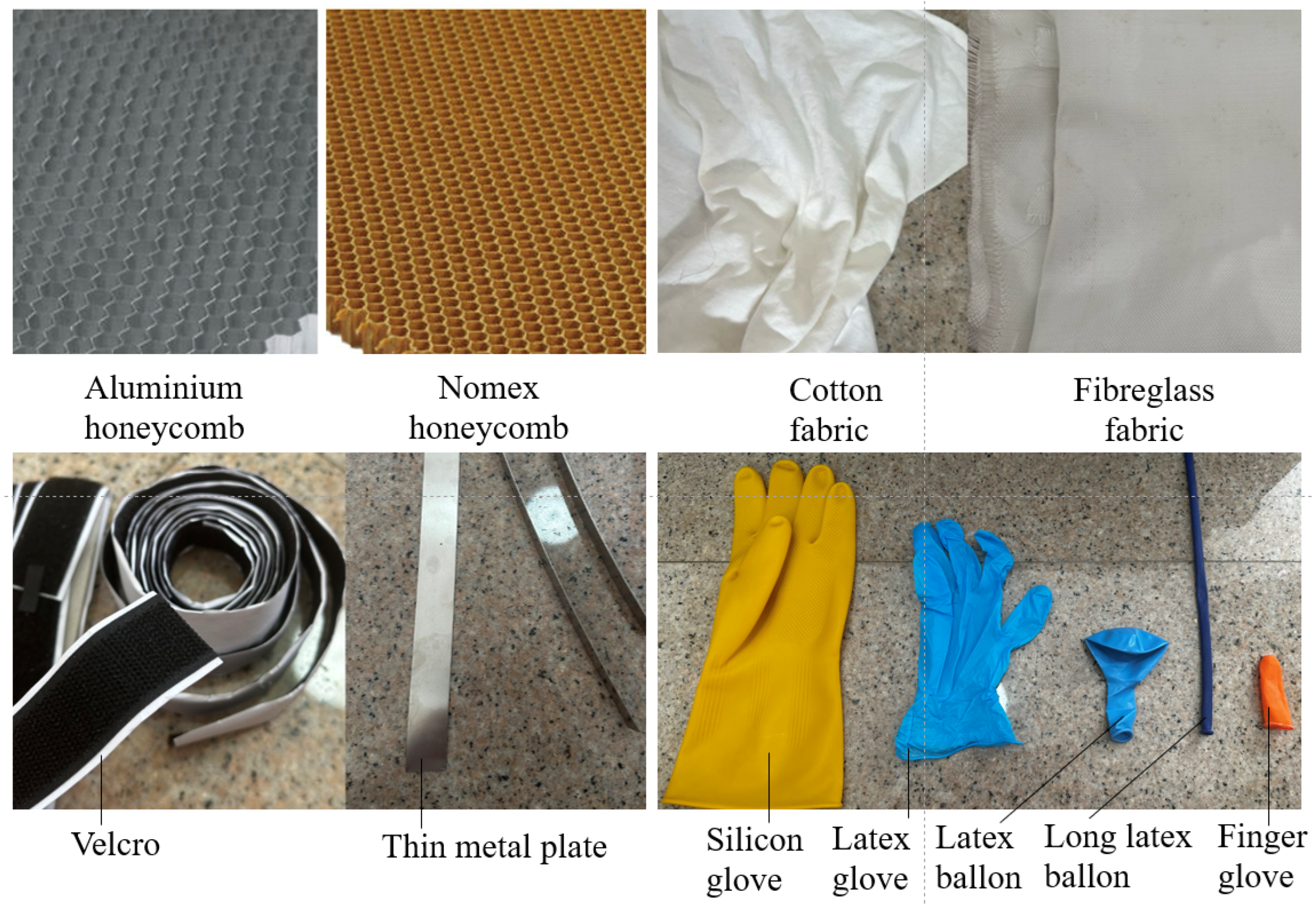
Two honeycomb materials, aluminum and Nomex honeycomb, were used in this paper as shown in Figure 3. The fabric sheet provides additional bending stiffness for the finger and prevents sliding between the honeycomb structure, and the outer membrane. In Figure 3), two kinds of fabric material were selected: cloth fabric made from knitted cotton and fiberglass fabric that can be molded into various shapes [45]. Also, the thicknesses of the cotton cloth and fiberglass fabric were 0.3 mm and 0.32 mm, respectively.

Reinforcements and Outer Membrane

Reinforcements can be added in between the honeycomb core and fabric to provide additional bending stiffness. The materials used as reinforcements are Velcro and thin metal plates (see Figure 3). The tiny hooks on the male side of the Velcro catch onto the honeycomb and prevent it from sliding on the fabric. Hence, this increases friction and interlocking forces between the honeycomb structure and membrane. Inserting a thin metal plate between the fabric and the honeycomb structure enables the honeycomb sandwich structure to return to its original position after deformation. The tried thicknesses of the stainless steel plates are 0.2, 0.5, and 1 mm. The function of the outer membrane is to provide an impermeable seal for the vacuum mechanism to control the stiffness of the honeycomb sandwich structure. The material for the membrane has to be flexible and elastic for the gripper to deform, i.e., silicon gloves, latex gloves, latex balloons, and finger gloves (see Figure 3).

3.2. Gripper Assembly and Control

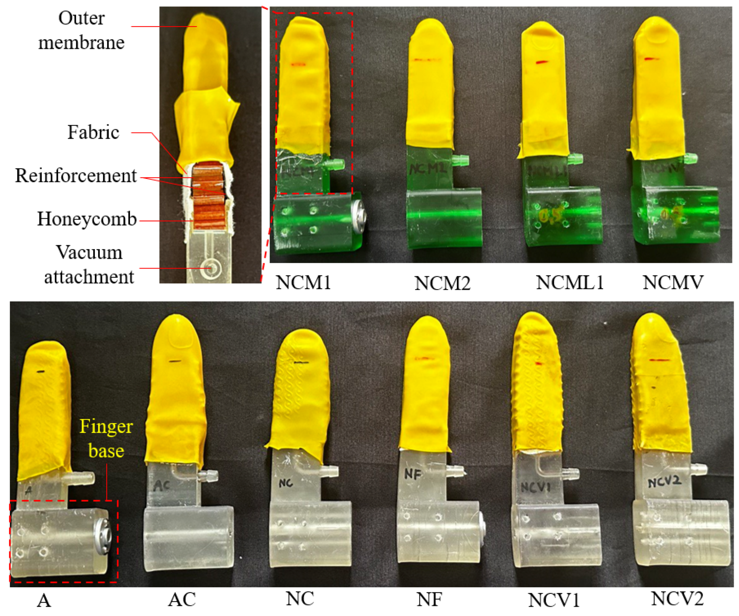
The steps to fabricate the jamming gripper finger are repeated with different materials (see Figure 3 and Figure 4), where two materials are considered for each component. Ten prototypes of the honeycomb jamming finger are made based on their combinations as shown in Table 1. Other parts made from PLA plastic are printed by 3D Ender-3 printer. Breakdown and assembly models of the gripper are shown in Figure 5 and Figure 6b). Two joysticks are incorporated with an Arduino Uno to serve the movements of the servo motor, linear actuator, and vacuum pump. The first joystick controls the servo motor, together with the vacuum pump. The second joystick operates the linear actuator. A flowchart of the controlling system is shown in Figure 6a).

4. Results

Three experiments are conducted in this section, including bending load tests, the effect of pressure on the Nomex honeycomb, and the grasping capability.

4.1. Bending Load Test

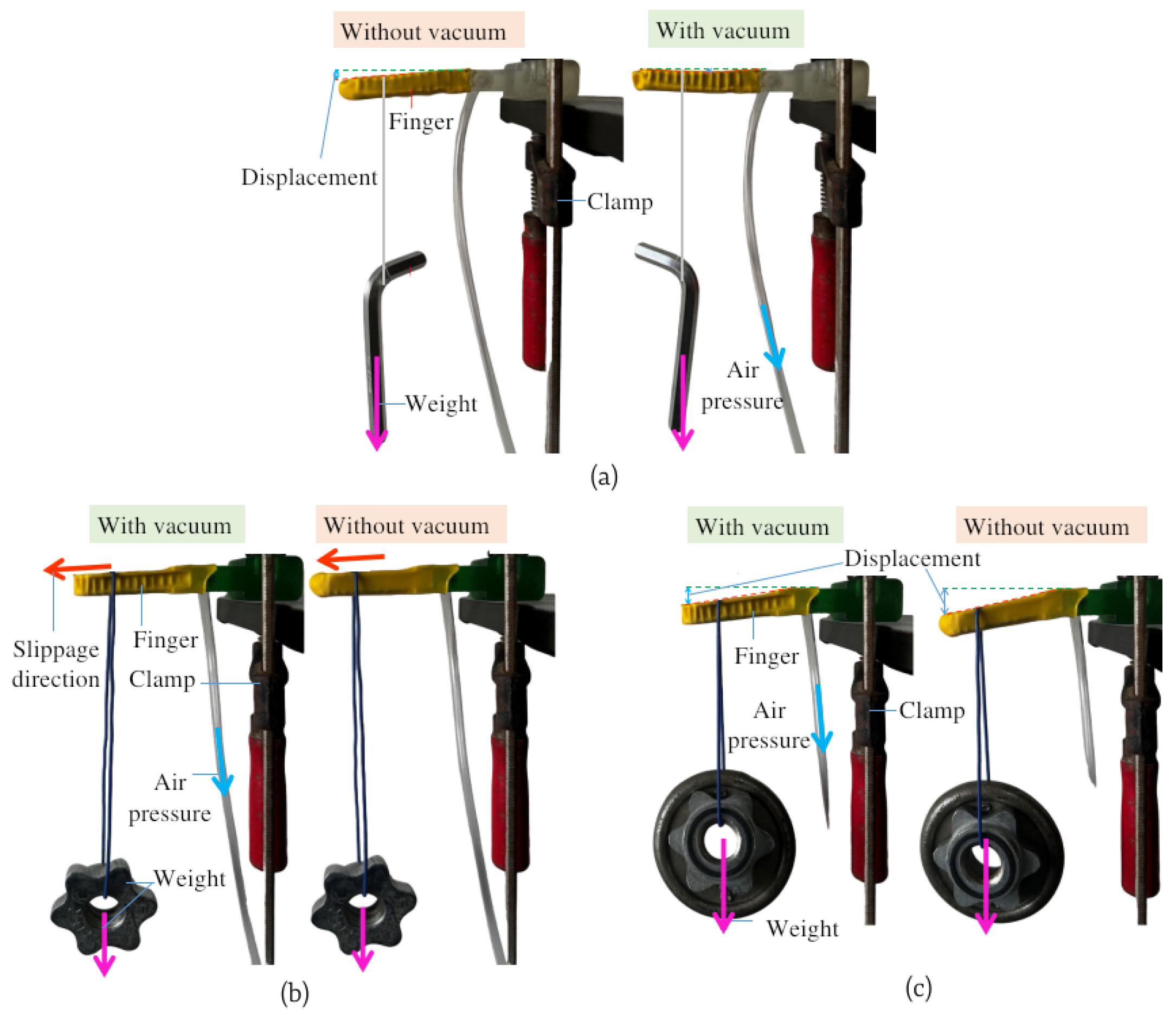
The bending load test aims to examine the behavior of honeycomb sandwich structures when subjected to bending moment. The setup involves measuring the vertical displacement of the finger before and after applying the loads. The experimental setup and force diagram are respectively illustrated in Figure 7a and Figure 8. In this scenario, the honeycomb jamming fingers are secured on the wall and hooked with a load (weight). The displacement of the fingertips is documented in two pneumatic conditions: without or with a vacuum pressure of 20 kPa and in 10, 30, 60, and 100 g weights.
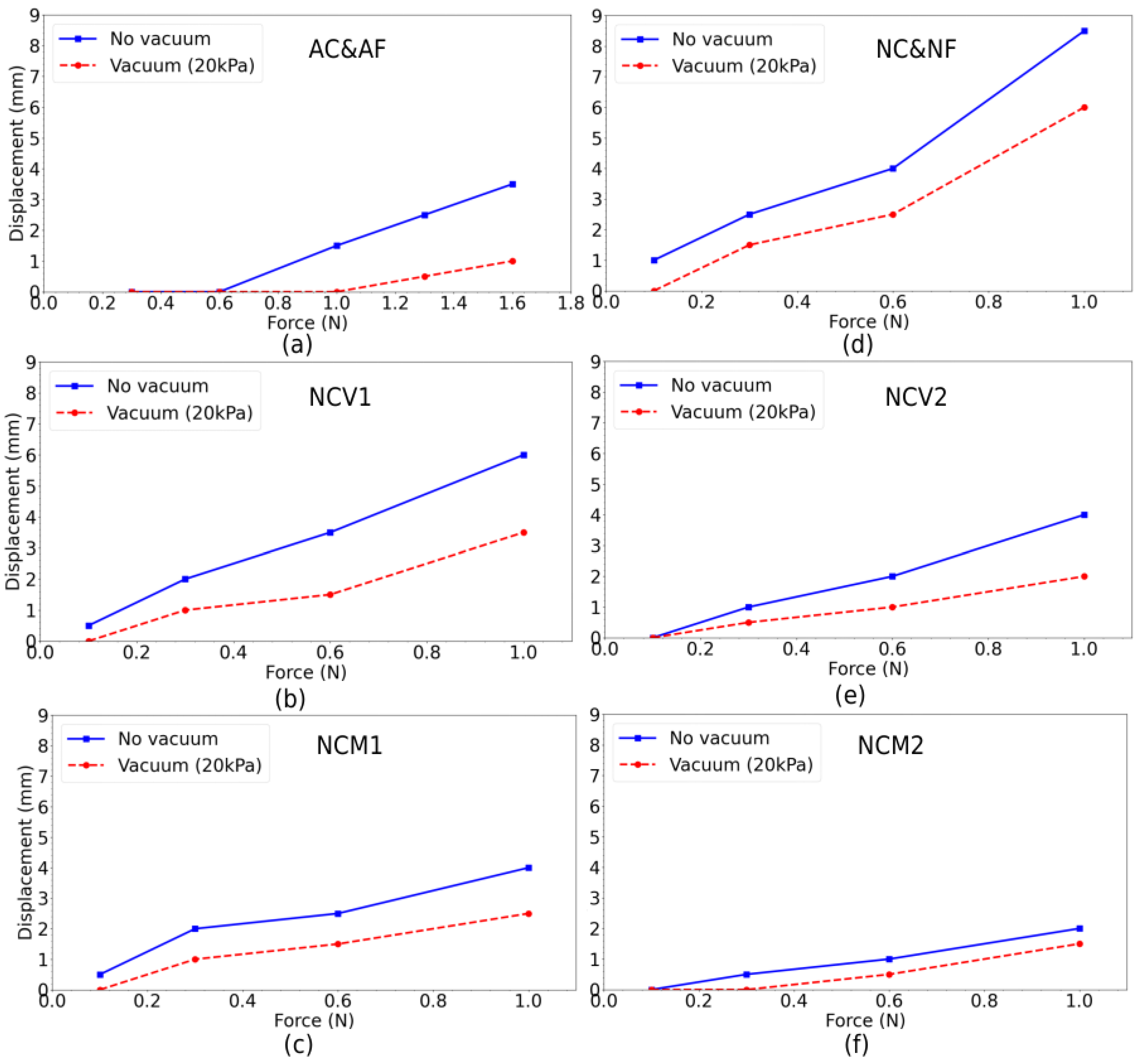
From the measurements taken, cloth fabric and fiberglass fabric had a very similar impact on the stiffness of the gripper, with identical displacement behavior (see Figure 8a,d). In general (see Figure 8), the results displayed lesser deformation under vacuum which aligns with the underlying working principles of the honeycomb jamming finger. In other words, the vacuum pressure increased the stiffness of the finger. The Nomex honeycomb exhibited linear elastic deformation followed by non-linear elastic deformation over the bending load whereas the aluminum honeycomb showed little to no deformation in both vacuum and no vacuum conditions. When the applied force exceeded 0.6 N, there was a noticeable increase in the level of deformation for the aluminum honeycomb sandwich under no vacuum condition. In contrast, when subjected to vacuum pressure, the aluminum honeycomb displayed greater stiffness and deformation was only observed beyond the 1 N threshold. After surpassing this threshold, the stiffness is reduced significantly with a linear relationship between force and deformation. Unfortunately, at this point, yielding has occurred resulting in permanent plastic deformation that can’t restore the original shape of the finger. In comparison to the aluminum honeycomb, the Nomex honeycomb showed a non-linear relationship with its force-displacement curves. Also, the stiffness changes more gradually and there is no permanent deformation observed. This makes it suitable to grip relatively soft material since the Nomex honeycomb would deform under a load as low as 0.3 N.
The results also displayed a similar nonlinear relationship with the Velcro and metal plate reinforcements installed. In Figure 9a, changing the number of the Velcro layers influenced the force on the jamming finger at 3 mm displacement. The force increased 20 and 100 % as appending one and two Velcro layers, respectively to the finger. The thickness of the metal plate powerfully affected the finger stiffness with 87.5 and 650% of increment after appending a 0.2 mm and 0.5 mm thickness of metal plate in to the finger (see Figure 9b). The number of reinforcement layers affected the stiffness of the finger, and the metal plate can make the finger stiffer than the Velcro. A high-stable finger would be useful for dealing with tasks requiring large force or moments. However, it is not an ideal option to work with soft objects or flexible tasks.

4.1.1. Reinforcement Comparison

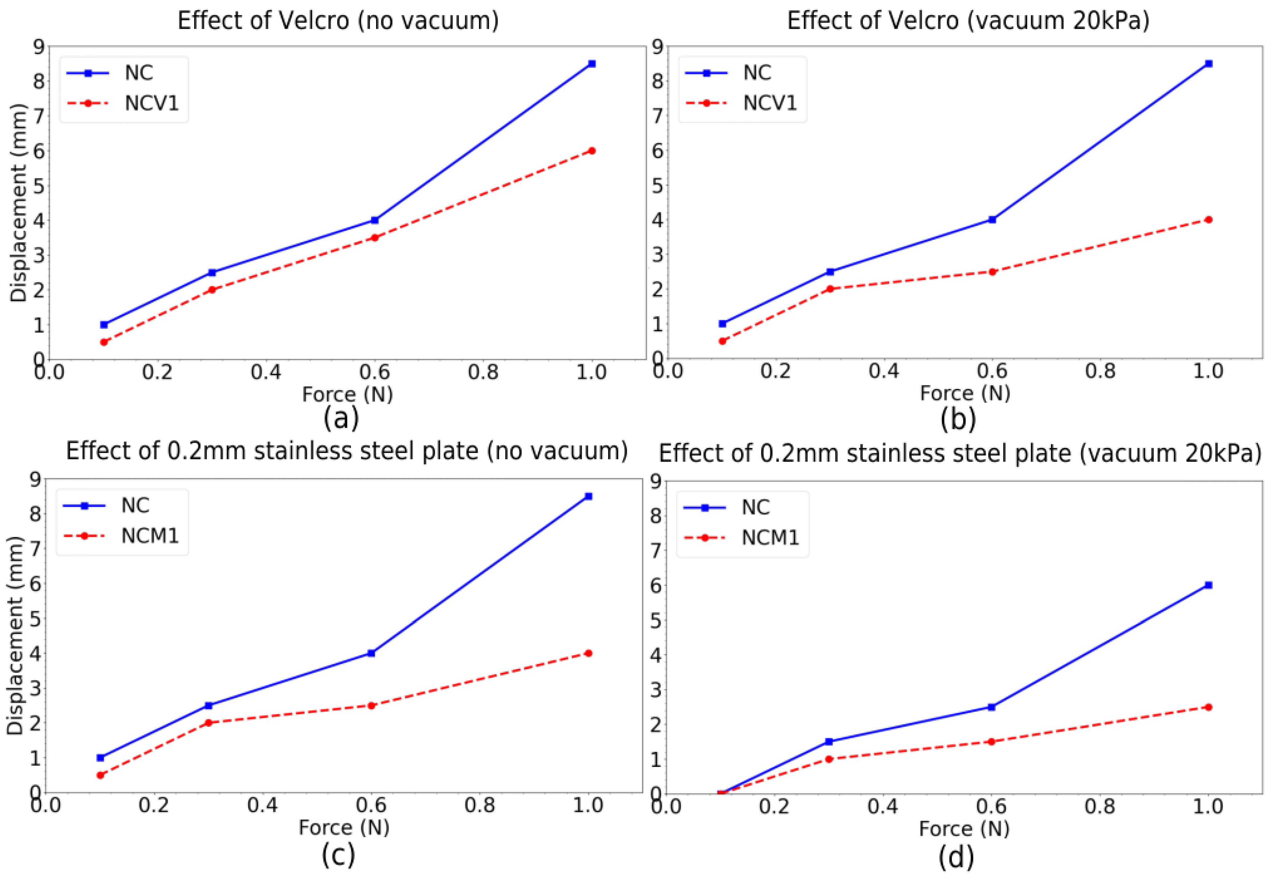
The results of the bending load test between the pairs NC, NCV1 and NC, NCMV1 were shown in Figure 10a,b and c,d, respectively. Overall, the reinforcements on two sides of the honeycomb increased the stiffness of the honeycomb sandwich structure via the smaller values of the finger displacement. Additionally, the gap of displacement curves in each graph increases under increasing the bending load increases or applying the vacuum suction. In this scenario, Velcro and steel plate can strengthen the stability of the sandwich structure under heavier loads thanks to decreasing slippage between the contact surfaces with the honeycomb. Unlike Velcro reinforcement, metal plate reinforcement does not prevent sliding and behaves similarly under ambient and vacuum conditions. However, the stainless-steel plate reinforcement helps to restore the tip of the gripper to its original position when the load is removed.

4.1.2. Statistical Result Analysis

To achieve a higher bending stiffness, a thicker stainless-steel plate 0.5 mm (aka NCM3) was explored in this experiment. The finger prototype with NCM3 displayed higher bending stiffness by taking on bending loads from 1 N to 10.8 N without experiencing permanent plastic deformation. The force-displacement graph for NCM3 is shown in Figure 11a. Another prototype of the finger made with Velcro and stainless-steel plate reinforcements (aka NCMV) allowed to reap the benefits of both reinforcements mentioned earlier and enabled taking on heavier bending loads up to 13 N, without undergoing permanent plastic deformation. The tests were replicated three times with six incremental loads and the average displacements and standard deviations (s.d.) are shown in Figure 11b. Three characteristic stages were distinguished in the force-displacement curves during the bending load tests for the NCMV prototype. The four stages indicated in Figure 11b are slip resistance stage, slip stage, linear elastic deformation, and non-linear elastic deformation.
Slip Resistance Stage: In the first phase of loading, the prototype displayed slip resistance, as the load was not sufficient to cause deformation due to the friction between the surfaces within the sandwich structure. This resulted in a minimal increase in deformation as the bending load increased, which coincided with the results. The mean displacement and standard deviation under a load of 1 N were zero. Figure 7b illustrates the slip resistance stage under a load of 2.2 N.
Slip Stage: The slip stage followed after the slip resistance stage, where the initial sliding began between the surfaces of the Nomex honeycomb, the Velcro, and the metal plate layers. At this stage, the load in the range of 2.2 to 5.3 N overcame the frictional resistance, and the honeycomb sandwich structure started to deform more rapidly.
Linear elastic deformation: After the slip stage, the force–displacement relationship became linear, as the honeycomb sandwich structure remained in its linear elastic limit. In the linear elastic region, the effect of vacuum pressure increased the stiffness of the honeycomb sandwich structure by 49.81%. Under a bending load of 5.3 N, the prototype experienced a lower displacement of 3 mm in vacuum pressure as compared to 4.33 mm under ambient condition.
Non-linear elastic deformation: Beyond the linear elastic limit, the honeycomb sandwich structure displayed its non-linear elasticity without experiencing permanent plastic deformation. It was able to return to its original position after the load was removed. This was unlike the usual material, where the material undergoes plastic deformation beyond its yield strength and experiences irreversible non-linear deformation. The bending loads used in this stage are shown in Figure 7c.
At 13 N, the standard deviation for the curve under ambient pressure increased as shown in the divergence in the standard deviation, whereas that of the vacuum case remained constant. In the non-linear elastic region, the decrease in gradient of the curves indicated a decrease in stiffness. As seen in Figure 11b, the curves transitioned from a steep to shallow profile, which could be useful, as a shallow slope indicates that it would be easy to control the gripper. The effect of pressure was also more significant under higher bending loads. At a relatively lower force of 7.5 N, a 20 kPa vacuum pressure reduced the displacement by 2 mm. Under a higher force of 13 N, the prototype experienced a lower displacement of 6.17 mm under vacuum pressure, reducing 3.66 mm compared with that under ambient pressure.

4.2. Effect of Pressure on the Honeycomb Jamming Finger

To determine the appropriate vacuum pressure for the jamming gripper, an experiment was conducted to observe the effect of pressure on the Nomex honeycomb. The jamming finger was subjected to incremental vacuum pressures of 10 kPa, with bending loads of 0.3 N, 0.6 N, and 1 N (see Figure 11c). This experiment was conducted using the same experimental setup as the bending load test. It was observed that vacuum pressure above 20 kPa would compress the Nomex honeycomb significantly and could damage the integrity of the structure. The force–displacement curve at 10 kPa was observed to be between 0 kPa and 20 kPa, indicating that the force–displacement curve converges towards a pressure of 20 kPa. Therefore, it can be concluded that the appropriate vacuum pressure for the jamming gripper is 20 kPa.

4.3. Demonstration

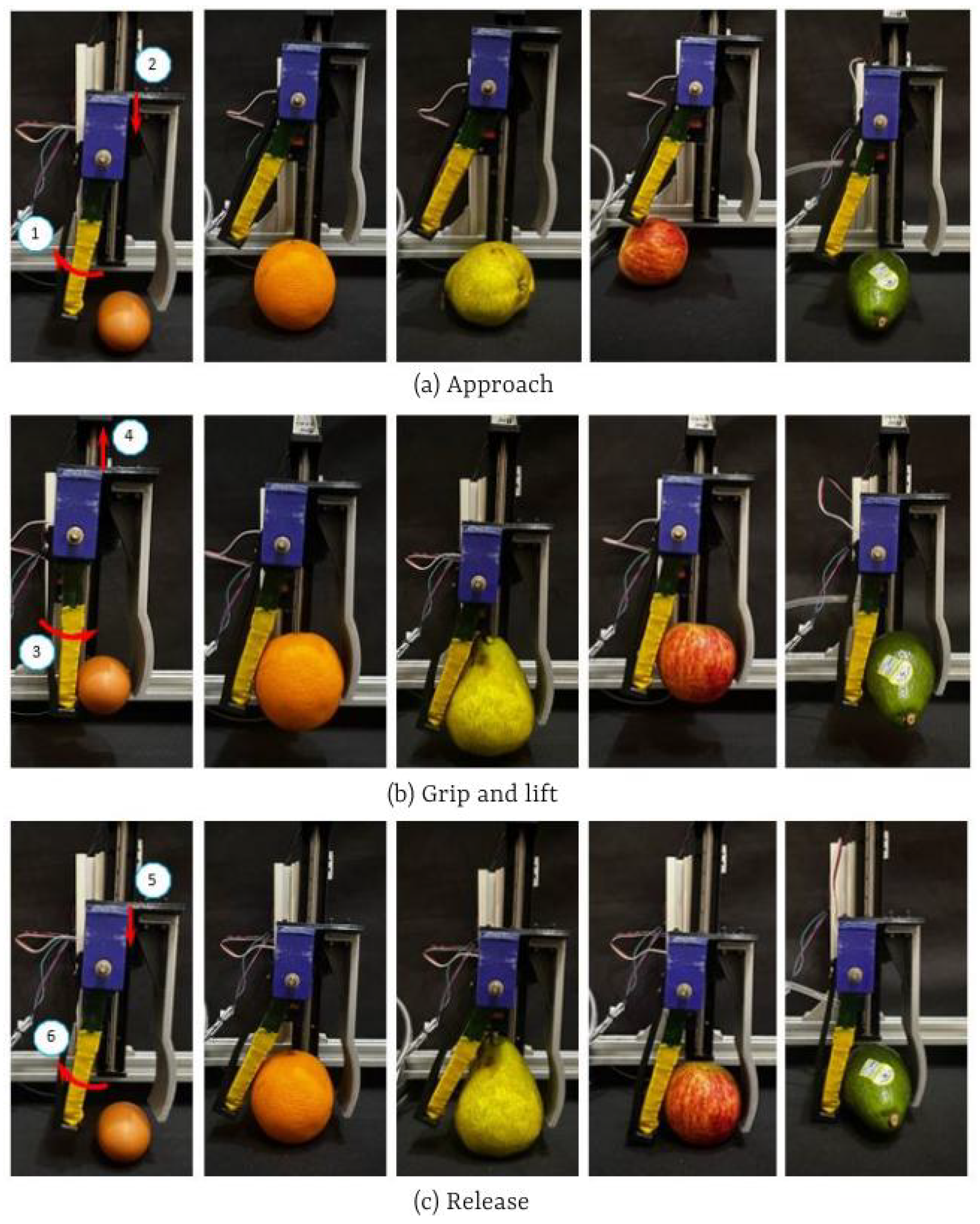
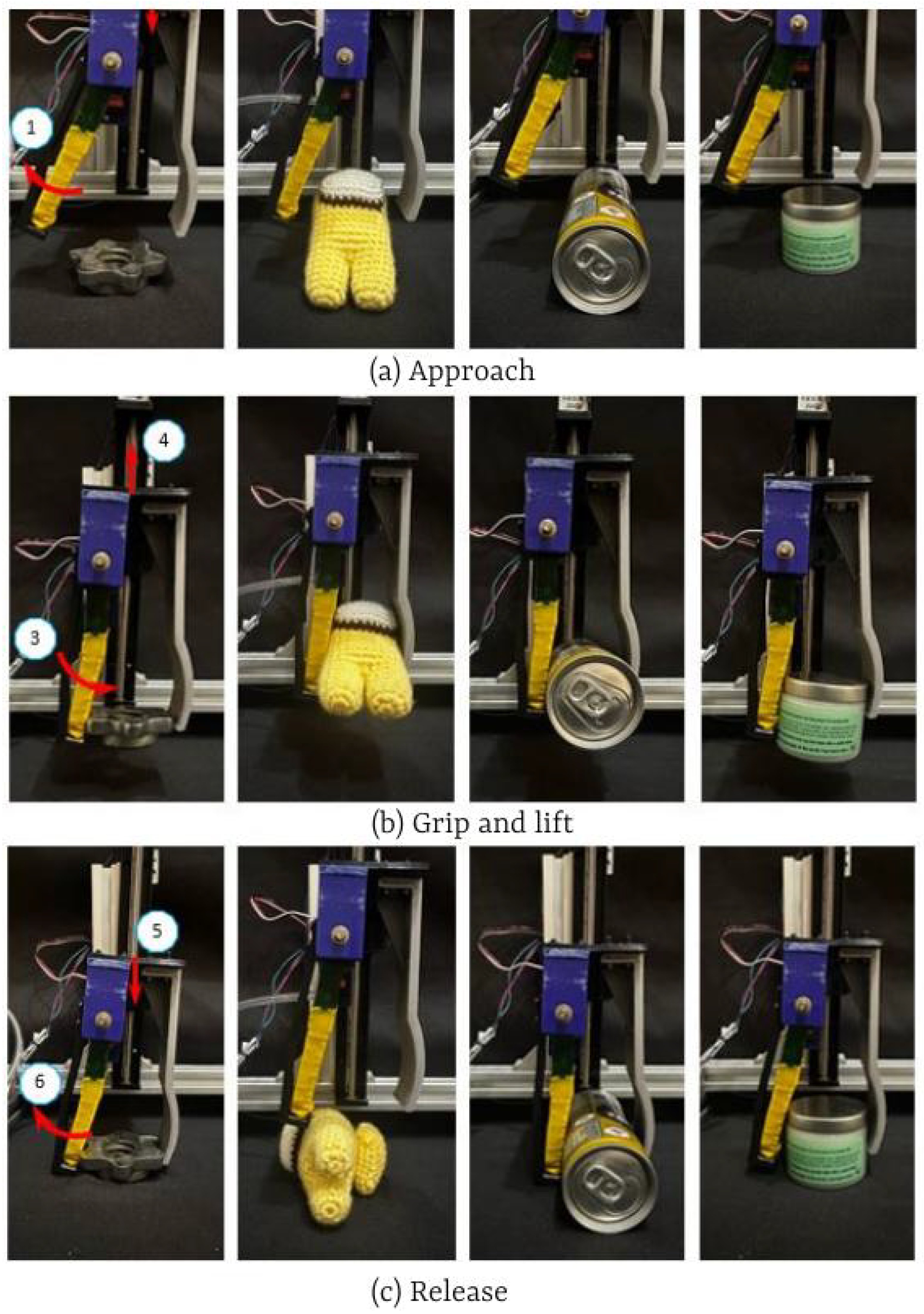
This subsection showcases the honeycomb jamming gripper’s capabilities to validate the operational readiness of the gripper by gripping various objects such as an egg, apple, orange, pear, avocado, metal object, soft toy, coffee can, and cylinder bottle with their configurations in Table 2. The test, including six steps, is illustrated in Figure 12 and Figure 13. In the first step, each object was placed on the floor such that its apex was under the fingertips and the gripper was completely opened. The gripper moved down to reach the object (step 2). Then, the finger closed and conformed to the object; concurrently, the vacuum was activated to lock the stiffness of the finger (step 3). The gripper held the object and moved up (step 4) and moved down back to the previous position (step 5). Finally, the finger opened and the gripper moved back to the initial position (step 6). The honeycomb jamming gripper, NCV1, easily picked up not only light and heavy, irregularly shaped objects such as the soft toy, metal component, coffee can, and cylinder bottle but also fragile objects like fruits and eggs without damaging them (see Figure 12 and Figure 13). This reveals that our proposed gripper can adapt to soft and hard objects with complex shapes thanks to the sandwich structure with variable stiffness from the vacuum suction. At step 3, in the no-vacuum state, the jamming finger was flexible and soft to adapt to the object surfaces. After generating the vacuum, the finger became stiffer, which stabilized the gripping force F z and the friction force F z . Depending on the properties of each object, we can control the vacuum to change the stiffness of the jamming finger. For heavy-duty tasks, such as assembling bolts, it is necessary to increase the number of reinforcement layers and the vacuum pressure to adjust the torque M z .

5. Conclusions

This study came up with the development of a honeycomb jamming gripper for handling heavy objects with variable stiffness. The Nomex honeycomb is ideal for building the core of the jamming finger, which is used to combine with various fabric materials and reinforcements in testing. In the linear elastic region, vacuum pressure increases the stiffness of the honeycomb sandwich structure by 49.81%. In the non-linear elastic region, the force–displacement curves transition from a steep to a shallow profile, which is beneficial in controlling the gripper. The displacement is reduced by a maximum of 37.2% under a vacuum pressure of 20 kPa. By varying the vacuum pressure, the honeycomb sandwich structure can transform between stiffness and flimsy states, which is useful for a slender and lightweight finger to carry heavier loads.

Author Contributions

Y.C.C.—design, experiment, and writing, W.T.C.—concept, and writing, funding acquisition and revision, V.P.N.—concept, design, analysis, writing, revision and proofreading. All authors have read and agreed to the published version of the manuscript.

Funding

This project was supported by Nanyang Technological University under the URECA Undergraduate Research Programme.

Institutional Review Board Statement

Not applicable.

Informed Consent Statement

Not applicable.

Data Availability Statement

Data are contained within the article.

Conflicts of Interest

The authors declare no conflicts of interest.

References

  1. Brown, E.; Rodenberg, N.; Amend, J.; Mozeika, A.; Steltz, E.; Zakin, M.R.; Jaeger, H.M. Universal robotic gripper based on the jamming of granular material. Proc. Natl. Acad. Sci. USA 2010, 107, 18809–18814. [Google Scholar] [CrossRef]
  2. Zhou, L.; Ren, L.; Chen, Y.; Niu, S.; Han, Z.; Ren, L. Bio-Inspired Soft Grippers Based on Impactive Gripping. Adv. Sci. 2021, 8, 2002017. [Google Scholar] [CrossRef] [PubMed]
  3. Bui, S.T.; Kawano, S.; Ho, V.A. ROSE: Rotation-based Squeezing Robotic Gripper toward Universal Handling of Objects. In Proceedings of the Robotics: Science and Systems, Daegu, Republic of Korea, 10–14 July 2023. [Google Scholar] [CrossRef]
  4. Goh, G.L.; Ng, T.Y. Joint angle prediction for a cable-driven gripper with variable joint stiffness through numerical modeling and machine learning. Int. J. AI Mater. Des. 2024, 1, 62. [Google Scholar] [CrossRef]
  5. Xuan Hiep, T.; My, C.A.; Van Binh, P.; Hieu, L.C. Innovative development of a soft robotic gripper: Mathematical modeling and grasping capability analysis. Mech. Based Des. Struct. Mach. 2024, 52, 4991–5018. [Google Scholar] [CrossRef]
  6. Nguyen, V.P.; Dhyan, S.B.; Mai, V.; Han, B.S.; Chow, W.T. Bioinspiration and Biomimetic Art in Robotic Grippers. Micromachines 2023, 14, 1772. [Google Scholar] [CrossRef]
  7. AboZaid, Y.A.; Aboelrayat, M.T.; Fahim, I.S.; Radwan, A.G. Soft robotic grippers: A review on technologies, materials, and applications. Sensors Actuators A Phys. 2024, 372, 115380. [Google Scholar] [CrossRef]
  8. Muralidharan, S.T.; Andrikopoulos, G.; Feng, L. A Survey on the Current Trends and Applications of Design Optimization for Compliant and Soft Robotics. In Proceedings of the 2023 IEEE/ASME International Conference on Advanced Intelligent Mechatronics (AIM), Seattle, DC, USA, 27 June–1 July 2023. [Google Scholar]
  9. Wang, X.; Lin, A.; Yuan, W.; Hu, H.; Cheng, G.; Ding, J. Design of an actuator with bionic claw hook–suction cup hybrid structure for soft robot. Bioinspir. Biomimetics 2024, 19, 036021. [Google Scholar] [CrossRef]
  10. Nguyen, V.P.; Chow, W.T.; Dhyan, S.B.; Zhang, B.; Han, B.S.; Wong, H.Y.A. Low-Cost Cable-Driven Robot Arm with Low-Inertia Movement and Long-Term Cable Durability. Robotics 2024, 13, 128. [Google Scholar] [CrossRef]
  11. Jo, Y.; Park, Y.; Son, H.I. A suction cup-based soft robotic gripper for cucumber harvesting: Design and validation. Biosyst. Eng. 2024, 238, 143–156. [Google Scholar] [CrossRef]
  12. Nguyen, P.V.; Luu, Q.; Takamura, Y.; Ho, V. Wet Adhesion of Micro-patterned Interfaces for Stable Grasping of Deformable Objects. In Proceedings of the 2020 IEEE/RSJ International Conference on Intelligent Robots and Systems (IROS), Las Vegas, NV, USA, 25–29 October 2020; pp. 9213–9219. [Google Scholar]
  13. Li, H.; Xie, D.; Xie, Y. A Soft Pneumatic Gripper with Endoskeletons Resisting Out-of-Plane Bending. Actuators 2022, 11, 246. [Google Scholar] [CrossRef]
  14. Le, P.H.; Thien, P.D.; Du, B.L. A Soft Pneumatic Finger with Different Patterned Profile. Int. J. Mech. Eng. Robot. Res. 2021, 110, 577–582. [Google Scholar]
  15. Li, S.; Yin, X.; Xia, C.; Ye, L.; Wang, X.; Liang, B. TaTa: A Universal Jamming Gripper with High-Quality Tactile Perception and Its Application to Underwater Manipulation. In Proceedings of the 2022 International Conference on Robotics and Automation (ICRA), Philadelphia, PA, USA, 23–27 May 2022; pp. 6151–6157. [Google Scholar]
  16. De Rodrigo, I.; Belart, J.; Lopez-Lopez, A.J. Universal Jamming Gripper: Experimental Analysis on Envelope and Granular Materials. Machines 2024, 12, 52. [Google Scholar] [CrossRef]
  17. Nguyen, P.V.; Sunil, D.B.; Chow, W.T. Soft-stable interface in grasping multiple objects by wiring-tension. Sci. Rep. 2023, 13, 21537. [Google Scholar] [CrossRef] [PubMed]
  18. Gai, L.J.; Huang, J.; Zhang, Y.; Zong, X.; Ding, H. A Soft Finger With Tensile Variable Stiffness Based on the Cross-Sliding Jamming Mechanism. IEEE Robot. Autom. Lett. 2024, 9, 3427–3434. [Google Scholar] [CrossRef]
  19. Clark, A.B.; Rojas, N. Stiffness-Tuneable Limb Segment with Flexible Spine for Malleable Robots. In Proceedings of the 2019 International Conference on Robotics and Automation (ICRA), Montreal, QC, Canada, 20–24 May 2019; pp. 3969–3975. [Google Scholar]
  20. Goh, G.L.; Goh, G.D.; Nguyen, V.P.; Toh, W.; Lee, S.; Li, X.; Sunil, B.D.; Lim, J.Y.; Li, Z.; Sinha, A.K.; et al. A 3D Printing-Enabled Artificially Innervated Smart Soft Gripper with Variable Joint Stiffness. Adv. Mater. Technol. 2023, 8, 2301426. [Google Scholar] [CrossRef]
  21. Chen, T.; Zhao, X.; Ma, G.; Tao, B.; Yin, Z. Design of 3D-printed Cable Driven Humanoid Hand Based on Bidirectional Elastomeric Passive Transmission. Chin. J. Mech. Eng. 2021, 34, 76. [Google Scholar] [CrossRef]
  22. Nikafrooz, N.; Leonessa, A. A Single-Actuated, Cable-Driven, and Self-Contained Robotic Hand Designed for Adaptive Grasps. Robotics 2021, 10, 109. [Google Scholar] [CrossRef]
  23. Kim, U.; Jung, D.; Jeong, H.; Park, C. Integrated linkage-driven dexterous anthropomorphic robotic hand. Nat. Commun. 2021, 12, 7177. [Google Scholar] [CrossRef] [PubMed]
  24. Ma, J.; Ge, S.S. Modeling and Control of an Octopus Inspired Soft Arm under Prescribed Spatial Motion Constraints. J. Intell. Robot. Syst. 2023, 109, 94. [Google Scholar] [CrossRef]
  25. Fu, J.t. A Novel Discrete Variable Stiffness Gripper Based on the Fin Ray Effect. In Intelligent Robotics and Applications; Springer: Cham, Switzerland, 2022; pp. 791–802. [Google Scholar]
  26. Yang, J.; Kang, R. Design of a Flexible Capture Mechanism Inspired by Sea Anemone for Non-cooperative Targets. Chin. J. Mech. Eng. 2022, 34, 77. [Google Scholar] [CrossRef]
  27. Deshpande, S.; Almubarak, Y. Octopus-Inspired Robotic Arm Powered by Shape Memory Alloys (SMA). Actuators 2023, 12, 377. [Google Scholar] [CrossRef]
  28. Cheng, P.; Jia, J.; Ye, Y.; Wu, C. Modeling of a Soft-Rigid Gripper Actuated by a Linear-Extension Soft Pneumatic Actuator. Sensors 2021, 21, 493. [Google Scholar] [CrossRef] [PubMed]
  29. Marullo, S.; Bartoccini, S.; Salvietti, G.; Iqbal, M.Z.; Prattichizzo, D. The Mag-Gripper: A Soft-Rigid Gripper Augmented With an Electromagnet to Precisely Handle Clothes. IEEE Robot. Autom. Lett. 2020, 5, 6591–6598. [Google Scholar] [CrossRef]
  30. The ability of underactuated hands to grasp and hold objects. Mech. Mach. Theory 2010, 45, 408–425. [CrossRef]
  31. Nam, N.D.; Linh, H.N.; Thanh-Phong, D.; Ngoc, L.C. Multi-objective optimization design for a sand crab-inspired compliant microgripper. Microsyst. Technol. 2019, 25, 3991–4009. [Google Scholar]
  32. Aeron, S.; Llontop, E.; Adler, A.; Agboh, W.C.; Dogar, M.; Goldberg, K. Push-MOG: Efficient Pushing to Consolidate Polygonal Objects for Multi-Object Grasping. In Proceedings of the 2023 IEEE 19th International Conference on Automation Science and Engineering (CASE), Auckland, New Zealand, 26–30 August 2023; pp. 1–6. [Google Scholar]
  33. Chen, H.; Zhu, J.; Cao, Y.; Xia, Z.; Chai, Z.; Ding, H.; Wu, Z. Soft-rigid coupling grippers: Collaboration strategies and integrated fabrication methods. Sci. China Technol. Sci. 2023, 66, 3051–3069. [Google Scholar] [CrossRef]
  34. Wang, Q.; Lu, X.; Jiang, P.; Guo, C.; Sun, Y. Research on a Variable-Stiffness Joint and Its Application in Actuators. Actuators 2023, 12, 397. [Google Scholar] [CrossRef]
  35. Zhang, Z.; Long, Y.; Chen, G.; Wu, Q.; Wang, H.; Jiang, H. Soft and lightweight fabric enables powerful and high-range pneumatic actuation. Sci. Adv. 2023, 9, eadg1203. [Google Scholar] [CrossRef]
  36. Li, D.; Chen, S.; Song, Z.; Liang, J.; Zhu, X.; Chen, F. Tailoring the in-plane and out-of-plane stiffness of soft fingers by endoskeleton topology optimization for stable grasping. Sci. China Technol. Sci. 2023, 66, 2026–2034. [Google Scholar] [CrossRef]
  37. Zhang, Z.; Fan, W.; Long, Y.; Dai, J.; Luo, J.; Tang, S.; Lu, Q.; Wang, X.; Wang, H.; Chen, G. Hybrid-Driven Origami Gripper with Variable Stiffness and Finger Length. Cyborg Bionic Syst. 2024, 5, 0103. [Google Scholar] [CrossRef]
  38. Sun, Y.; Liu, Y.; Pancheri, F.; Lueth, T.C. LARG: A Lightweight Robotic Gripper With 3-D Topology Optimized Adaptive Fingers. IEEE/ASME Trans. Mechatronics 2022, 27, 2026–2034. [Google Scholar] [CrossRef]
  39. Govindan, N.; Ramachandran, B.; Sai, P.H.V.; Krishna, K.M. A Novel Hybrid Gripper Capable of Grasping and Throwing Manipulation. IEEE/ASME Trans. Mechatronics 2023, 28, 3317–3328. [Google Scholar] [CrossRef]
  40. Nguyen, V.P.; Chow, W.T. Wiring-Claw Gripper for Soft-Stable Picking up Multiple Objects. IEEE Robot. Autom. Lett. 2023, 8, 3972–3979. [Google Scholar] [CrossRef]
  41. Nguyen, P.V.; Le, T.L. Hybrid robot hand for stably manipulating one group objects. Arch. Mech. Eng. 2022, 69, 375–391. [Google Scholar] [CrossRef]
  42. Seo, Y.S.; Lee, J.Y.; Park, C.; Park, J.; Han, B.K.; Koh, J.S.; Kim, U.; Rodrigue, H.; Bak, J.; Song, S.H. Highly Shape-Adaptable Honeycomb Gripper Using Orthotropic Surface Tension. IEEE Trans. Ind. Electron. 2024, 71, 2662–2671. [Google Scholar] [CrossRef]
  43. Lalegani Dezaki, M.; Bodaghi, M.; Serjouei, A.; Afazov, S.; Zolfagharian, A. Soft Pneumatic Actuators with Controllable Stiffness by Bio-Inspired Lattice Chambers and Fused Deposition Modeling 3D Printing. Adv. Eng. Mater. 2023, 25, 2200797. [Google Scholar] [CrossRef]
  44. Roth, F.; Eschen, H.; Schüppstuhl, T. The Loop Gripper: A Soft Gripper for Honeycomb Materials. Procedia Manuf. 2021, 55, 160–167. [Google Scholar] [CrossRef]
  45. Uses of Fiberglass Fabrics. Available online: https://rb.gy/4tiv5f (accessed on 28 April 2024).
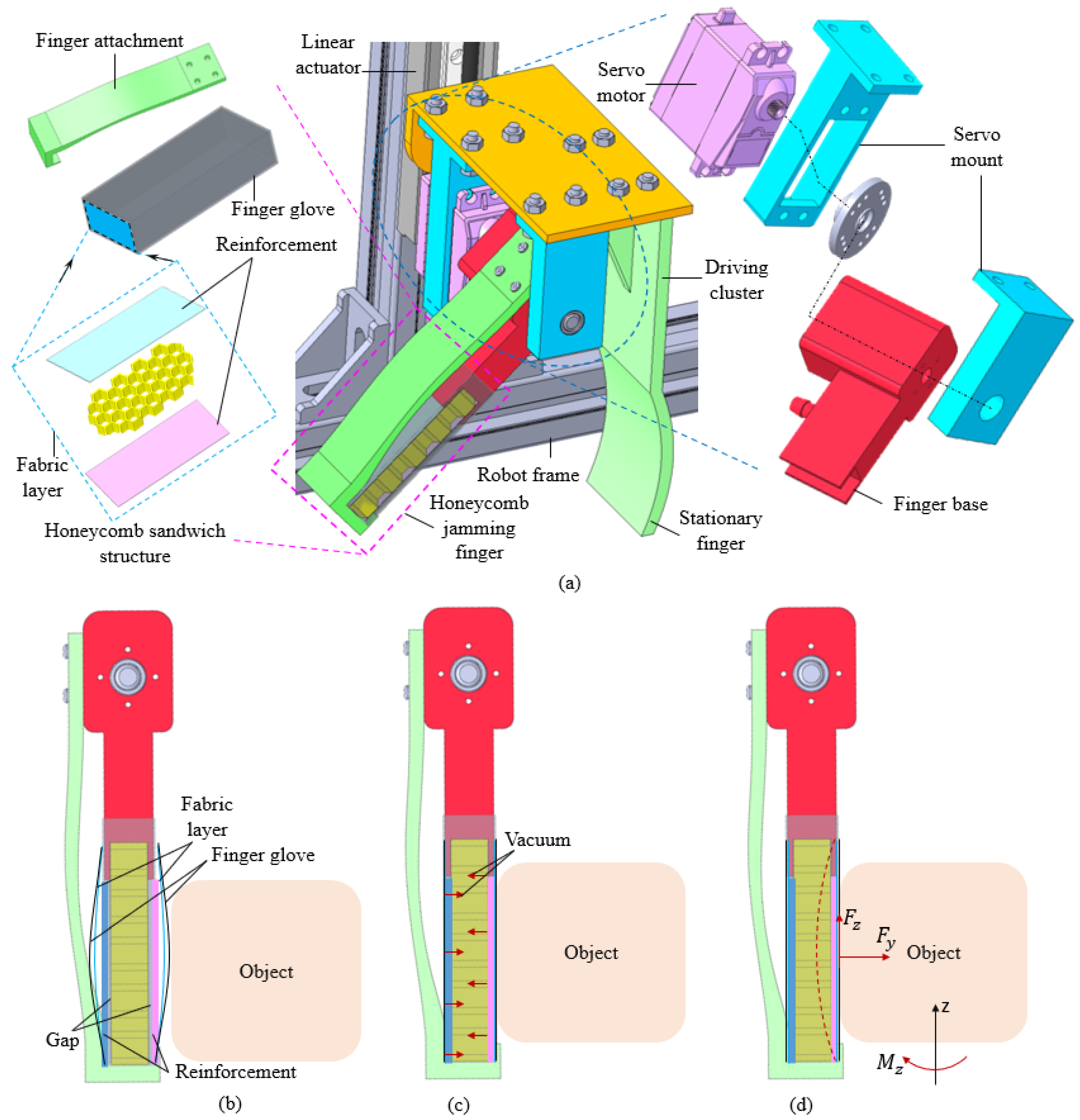
Figure 1. CAD model of final honeycomb jamming gripper (a), its working principle without (b) and with vacuum suction (c), and load capabiity (d). In (a), pink and blue dash-line boxes illustrate the finger structure and the driving system, respectively. In (d) the red dash-line curve shows the bending shape of the jamming finger after squeezing the object; concurrently, F y , F z , M z are the forces and momentum along the y , z directions, respectively.
Actuators 13 00359 g001
Figure 2. Design of the honeycomb jamming finger: (a) isometric view and (b) cross-sectional view.
Actuators 13 00359 g002
Figure 3. Material consideration for the design of the honeycomb jamming finger regarding honeycomb, fabric, reinforcement and membrane layers.
Actuators 13 00359 g003
Figure 4. Fabrication of honeycomb jamming finger with various material combinations as listed in Table 1.
Actuators 13 00359 g004
Figure 5. Breakdown of the honeycomb gripper and the driving system.
Actuators 13 00359 g005
Figure 6. Schematic of the electronic circuit for the gripper design (a) and fabricated honeycomb jamming gripper (b).
Actuators 13 00359 g006
Figure 7. Bending load test for the honeycomb jamming finger without and with vacuum (a). Slip resistance stage without and with vacuum (b). Non-linear elastic deformation without and with vacuum (c).
Actuators 13 00359 g007
Figure 8. Force-displacement graphs in cases of without and with vacuum in different material combinations (a) and AF, (b) NCV1, (c) NCM1, (d) NC and NF, (e) NCV2, and (f) NCM2.
Actuators 13 00359 g008
Figure 9. Comparisons of finger stiffness by documenting the force at 3 mm displacement between without Velcro, 1 layer Velcro and 2 layers Velcro (a) and without metal, 0.2 mm metal layer and 0.5 mm metal layer (b).
Actuators 13 00359 g009
Figure 10. Effect of Velcro on force-displacement curves for Nomex + Cotton cloth configuration under without (a) and with vacuum (b). Effect of 0.2 mm Stainless-steel on force-displacement curves for Nomex + Cotton cloth configuration under without (c) and with vacuum (d).
Actuators 13 00359 g010
Figure 11. Force–displacement curve for Nomex + cotton cloth + 0.5 mm metal plate (a) and Nomex + cotton cloth + 0.5 mm metal plate + Velcro (b) without and with vacuum. Effect of pressure on Nomex honeycomb (c).
Actuators 13 00359 g011
Figure 12. Honeycomb jamming gripper grasping food such as eggs and fruits, such as an orange, pear, apple, and avocado. The manipulations were captured in three phases: approach (a), grip and lift (b), and release (c). The motions of the fingers and gripper are indicated by the arrows together with their order numbers 1-6.
Actuators 13 00359 g012
Figure 13. Honeycomb jamming gripper grasping complex shapes such as metal component, soft toy, coffee can, and cylinder bottle. The manipulations were captured in three phases: approach (a), grip and lift (b), and release (c). The motions of the fingers and gripper are indicated by the arrows together with their order numbers 1-6.
Actuators 13 00359 g013
Table 1. List of material combinations for honeycomb jamming gripper finger.
CombinationAcronym
Aluminum + Cotton ClothAC
Aluminum + Fiberglass fabricAF
Nomex + Cotton ClothNC
Nomex + Fiberglass fabricNF
Nomex + Cotton Cloth + Velcro 1 sideNCV1
Nomex + Cotton Cloth + Velcro 2 sideNCV2
Nomex + Cotton Cloth + 0.2 mm Metal plate 1 sideNCM1
Nomex + Cotton Cloth + 0.2 mm Metal plate 2 sideNCM2
Nomex + Cotton Cloth + 0.5 mm Metal plate 1 sideNCM3
Nomex + Cotton Cloth + 0.5 mm Metal plate + VelcroNCMV
Table 2. Object pick-up tasks.
ObjectsMass (g)Diameter (cm)Pick Up
Egg504.3
Apple1507.5
Orange2007.8
Pear2707.6
Avocado1905.5
Metal object2206.8
Soft toy255.2
Coffee can3305.0
Cylinder bottle856.0
Disclaimer/Publisher’s Note: The statements, opinions and data contained in all publications are solely those of the individual author(s) and contributor(s) and not of MDPI and/or the editor(s). MDPI and/or the editor(s) disclaim responsibility for any injury to people or property resulting from any ideas, methods, instructions or products referred to in the content.