Abstract
A method for measuring multi-joint finger trajectories is proposed using MediaPipe. In this method, a high-speed camera is used to record finger movements. Subsequently, the recorded finger movement data are input into MediaPipe, where the system automatically extracts the coordinate data of the key points in the finger movements. From this, we obtain data pertaining to the trajectory of the finger movements. In order to verify the accuracy and effectiveness of this experimental method, we compared it with the DH method and the Artificial keypoint alignment method in terms of metrics such as MAPE (Mean Absolute Percentage Error), maximum distance error, and the time taken to process 500 images. The results demonstrated that our method can detect multiple finger joints in a natural, efficient, and accurate manner. Then, we measured posture for three selected hand movements. We determined the position coordinates of the joints and calculated the angular acceleration of the joint rotation. We observed that the angular acceleration can fluctuate significantly over a very short period of time (less than 100 ms), in some cases increasing to more than ten times the initial acceleration. This finding underscores the complexity of finger joint movements. This study can provide support and reference for the design of finger rehabilitation robots and dexterous hands.
1. Introduction
The human hand is the most flexible part of the human body. Its unique structure and close connection to the brain’s motor nervous system have consistently been the focus of research on the integration of medicine and engineering [1,2]. Analyzing the characteristics of finger movement can be applied to various practical fields, including rehabilitation and health care [3,4,5,6], ergonomics, medical image analysis, sports, and the development of bionic mechanisms and manufacturing. By detecting the electromyographic signals of the arm, Shi et al. demonstrated that specific movements of human fingers correspond to distinct action patterns and movement rules [7]. Ozioko et al. employed a motion capture system to reveal significant differences in the movements of various joints of human fingers, and they found no differences between genders [8]. Zhu et al. applied the grasping concept to the study of fingertip trajectories, changing the random movement of a gesture to a grip on a fixed object. This strategy greatly reduces the influence of non-objective factors during the experiment [9].
Finger rehabilitation robotics aims to optimize finger movement trajectories for patients with arm nerve damage or stroke-induced dysfunction. By precisely replicating healthy finger motions through mechanical actuation, it stimulates the damaged brain areas, fostering neuroplasticity and functional recovery. Accuracy and naturalness of these movements significantly impact rehabilitation effectiveness [7,8]. Therefore, thoroughly studying and accurately simulating complex human finger motions is crucial for advancing finger rehabilitation robot technology and enhancing treatment outcomes [10].
Currently, the predominantly used methods to study finger trajectories are the Denavit–Hartenberg (DH) method and the artificial keypoint alignment method. A coordinate system is established on the finger joints of each finger, and a 4 × 4 homogeneous transformation matrix is employed to describe the spatial relationship between adjacent links, thereby establishing the robot’s coordinates. The kinematic equation of the finger is derived using the tethered expression. While the DH method is straightforward and conducive to dynamic analysis, its application to finger motion simplifies the motion as purely revolute, assuming the rotational joint’s center of rotation to be the joint’s geometric center [11]. The artificial keypoint alignment method uses manual marking of key points in the image, recording and organizing them to obtain basic information. Park et al. used angle sensors to measure the rotation angles of each joint of the index finger and then analyzed the relationship between the specific motion states of the metacarpophalangeal, proximal, and distal finger joints [12]. Wang et al. tracked finger movements in LabVIEW software. Hand finger joints were marked and tracked and analyzed using software [13]. Yu et al. used computed tomography (CT) to capture images of finger joints and thus assess the state of motion of these joints, obtaining their motion trajectories [14]. The disadvantage of this method is that it is too inefficient to detect a coherent movement of the fingers.
The MediaPipe detection system, released by Google, is a sophisticated machine vision tool that boasts mature training capabilities and high accuracy. Notably, it can directly extract hand keypoint information [15]. Gökhan Güney and his colleagues utilized MediaPipe to evaluate the impact of drugs by analyzing the finger movement trajectories of patients with Parkinson’s disease [16]. Likewise, Haji Mohd et al. employed MediaPipe to achieve swift and robust hand detection and tracking, making use of deep learning technology in their analysis of a set of 10 gesture videos [17]. MediaPipe’s finger joint functionality transforms image data into keypoint data, resulting in a comprehensive keypoint dataset. Its recognition accuracy averages at 95.7% [18], which more than meets the accuracy demands of this experiment.
The time it takes for a natural finger to move once is approximately 0.5 s. Consequently, there is a need for a system that can accurately capture a substantial amount of information within a short time frame. The average digital camera operates at a frame rate of 30 to 60 frames per second (fps), which is often inadequate for capturing sufficient data. Therefore, the Mini-AX100de1 high-speed camera is utilized in this paper to guarantee sufficient data acquisition. The advantages of high-speed camera shooting include the elimination of post-correction circuitry, resulting in black and white images that maintain the integrity of the original data. Furthermore, the images captured by high-speed cameras are saved in strict accordance with the shooting sequence. For example, if the frame rate is set to 500 fps, the interval between each frame is 2 ms. This is crucial because the MediaPipe system processes frames individually, ensuring that the time interval of the obtained data remains consistently 2 ms. This consistency significantly simplifies subsequent experimental data processing and provides valuable insights for the simulation and control of finger-related movements.
We integrated the MediaPipe hand detection model with a high-speed camera to devise a measurement methodology. This methodology efficiently and precisely tracks the motion trajectories of multiple finger joints in a seamless way.
2. Biological Structure of Human Fingers
Current research on finger movement suggests that it encompasses not only the rotation of the phalanges but also the involvement of soft tissues, including ligaments and muscles. Consequently, the rotation of the fingers is often accompanied by additional influencing factors, such as the rotation of the joints, the stretching of the ligaments, and the interaction of muscle tissue. According to Chinese national standards, the anatomical structure of finger bones is shown in Figure 1. The distal interphalangeal (DIP) and proximal interphalangeal (PIP) joints of 3, and 4 in Figure 1 each contain one rotational degree of freedom, and the metacarpophalangeal (MCP) joint of 1 and 3 in Figure 1 contains two rotational degrees of freedom. The thumb metacarpophalangeal joint and interphalangeal joint (IP) each contain one degree of rotational freedom. Statistically, the length range of each segment of the finger is illustrated in Figure 2. The range of motion of each joint is shown in Table 1.
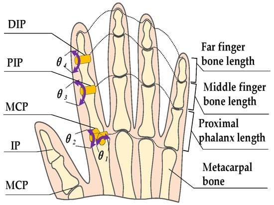
Figure 1.
Schematic diagram of the physiological structure of the finger.
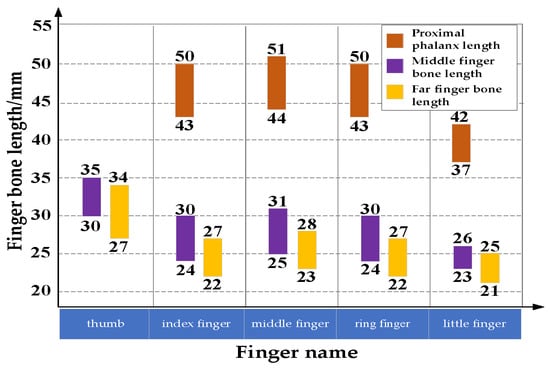
Figure 2.
Statistical values of finger bone length ranges.

Table 1.
Range of motion of adult finger joints.
In this experiment, the proximal phalanx, middle phalanx, and distal phalanx of the index finger are respectively 46.5 mm, 25 mm, and 23 mm, which meet the above standards for finger joint dimensions.
3. Measurement Methods
3.1. Experimental Principle
In the non-contact state, a high-speed camera captures the movement of the finger, generating the corresponding trajectory images. These images are then imported into the MediaPipe algorithm using Python programming, from which the position coordinates of key points in each image are extracted. Subsequently, the motion trajectories of the finger joints are constructed. Figure 3 depicts the experimental setup block diagram for the trajectory measurement based on the MediaPipe method.
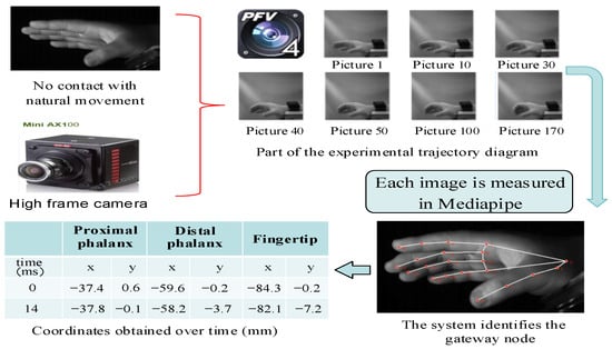
Figure 3.
Experimental flow chart of the trajectory measurement based on the MediaPipe method.
3.2. Experimental Objectives and Platform Construction
This experiment centers on finger rehabilitation as its experimental context. Wearable finger robots have emerged as a primary option for rehabilitation of patients with hand movement disorders [3]. Whether the motion trajectory of the finger rehabilitation robot can match the motion trajectory of the finger joints of normal people is a crucial indicator to measure the effectiveness of the finger rehabilitation robot [19]. Therefore, it is essential to develop a comprehensive set of measurement methods for finger multi-joint trajectories that can assess movement naturally and continuously, while ensuring high efficiency and accuracy. Five participants were selected, and three postures were tested. Each posture was consecutively evaluated with a 5-min interval between posture changes to mitigate participant fatigue. The HD camera experiment platform was established, as shown in Figure 4 and Figure 5.
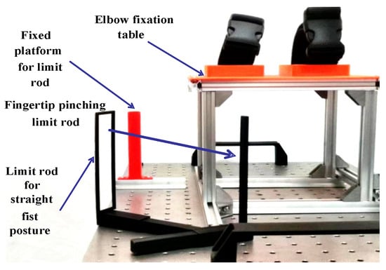
Figure 4.
Hand fixed platform and gesture locator.
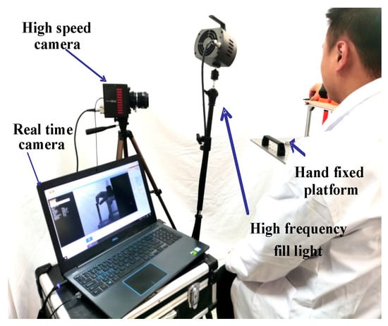
Figure 5.
Experimental operating platform.
During the experiment, the right hand was placed on the hand fixation platform and further stabilized on the elbow fixation table. This was done to prevent potential errors arising from unintentional sliding of the elbow during the course of the experiment. Then, the experiment commenced. Image information was fed back to the screen via PFV4 software. While ensuring the safety of the participants, the efficiency and quality of the experiment were greatly enhanced. It is important to ensure that the movement of the test finger is perpendicular to the camera. In this manner, even a single camera can fulfill the experimental requirement of accurately measuring finger motion trajectories [20]. Furthermore, in order to meet the high frame rate requirement of 500 frames per second (fps) used in this experiment, a high-frequency fill light lamp was installed to maintain consistent lighting conditions throughout the experiment and minimize the impact of lighting variations on the experimental results. The above applies to any finger, and this article utilizes the index finger as an illustrative example.
3.3. Experimental Testing and Results
First, determine the finger posture of the experiment. One thing to note is that the abduction and adduction movements of the fingers have relatively little functional impact on daily activities of the human body [21]. Therefore, this experimental design does not include such finger movements in the category of capture and analysis. Three of the most common and mature finger movement observation methods were employed [22,23]: palmar grasp, pincer grasp, and the straightening posture, as shown in Figure 6.
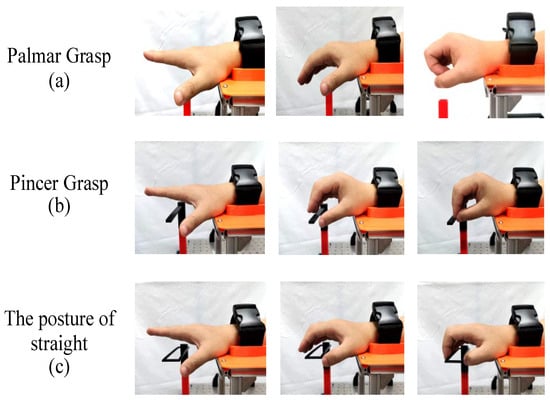
Figure 6.
The process of three gestures. (a) The palmar grasp simulates the natural state of the hand when grasping an object. While exercising the coordination of finger muscles, it also involves the flexibility of the MCP joints; (b) the pincer grasp gesture helps to increase the strength and flexibility of the fingers. In particular, it exercises the backward drive of the MCP joints and the coordinated control of the PIP and DIP joints; (c) the posture of straight exercises the upward drive movement of the MCP joints, and can fully exercise the DIP joints. It is very beneficial for the recovery of pushing, grasping, and other movements.
Because of gestures b and c, there is no fixed sign of completion that ensures the precise definition and specification of the experiment. The corresponding limit device is designed to ensure the reliability and repeatability of the experimental results [9].
Taking the palmar grasp, for example, high-precision image sets are first acquired through high-resolution cameras. Subsequently, using the written Python program, the image group is input into the MediaPipe system. By comparing with the keypoint map in the MediaPipe system, the coordinate system of each joint is output. To elucidate the process of the experimental system in detail and to verify the accuracy of the experiment, it is ensured that the actual node of the finger coincides with the keypoints identified by the system, as illustrated in Figure 7. Finally, as presented in Table 2, the coordinate positions of the finger nodes are obtained.

Figure 7.
System test drawing and actual effect test drawing. (a) Illustration of 21 Key points in the MediaPipe system; (b) proof of alignment between the actual image and the MediaPipe system.

Table 2.
A partial coordinate schematic table (in mm) based on the trajectory measurement based on the MediaPipe method.
We repeat the aforementioned process to acquire relevant data. Then, we use the nonlinear least squares method to fit the parameters. The quadratic sine function serves as the theoretical model. Through this approach, we derive the equations of fit for the motion trajectories of each node, presented in Table 3. The fit results are shown in Figure 8.

Table 3.
The equations of fit for the trajectory of each keypoint of the trajectory measurement based on the MediaPipe method.

Figure 8.
Motion trajectory fitting diagrams for the three joints of the palmar grasp. (a) The curve fitting the PIP joint motion trajectory; (b) the curve fitting the DIP joint motion trajectory; (c) the curve fitting the fingertip joint motion trajectory.
4. Comparison of Experimental Methods
We want to evaluate the effectiveness of the method, that is, whether it can be measured naturally with high efficiency, high accuracy, and can detect multiple joints of fingers. Using the DH method and the artificial keypoint alignment method, the gripping motion was selected for testing. We have verified the superiority of the new scheme through comprehensive comparison.
4.1. DH Method and the Artificial Keypoint Alignment Method
The DH method involves establishing a coordinate system on each link and representing the spatial position using a 4 × 4 homogeneous transformation matrix. We set up the finger’s DH coordinate system, as shown in Figure 9. Then, additionally, the data presented in Table 1 are converted into parameters that conform to the DH method, which are shown in Table 4.
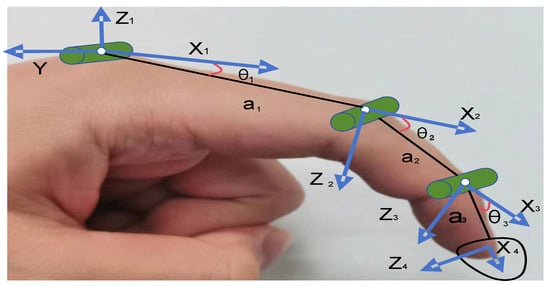
Figure 9.
Coordinate system of index finger DH method.

Table 4.
Related parameters of DH method for the index finger.
Based on the information provided in Table 4, the pose transformation matrix for the finger joint coordinate system is constructed, and the transformation matrix for each link is expressed as follows:
where is the transformation matrix of the corresponding joint, and the transformation matrix of each connecting rod is expressed as follows:
The pose of the end of the index finger relative to the base coordinate system can be obtained by multiplying the connecting rod transformation matrix in turn. At the same time, the position vector of each node in turn can be obtained. The node near the finger: L, Distal connector: R, Fingertip endpoint: P.
The artificial keypoint alignment method primarily involves manually marking key points in the image and recording the data using the image annotation software Labelme. In order to ensure the accuracy of the experiment, before the experiment, it was ensured that the recognition point of the MediaPipe system, the center of the recognition icon on the human hand, and the joint points of the index finger coincided with each other before the experiment. The three-point coincidence diagram is shown in Figure 10.
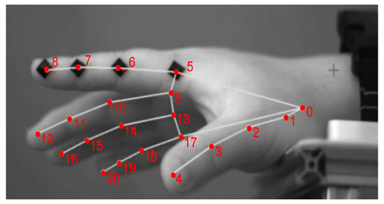
Figure 10.
MediaPipe system identification point, identification icon center point and index finger node coincidence image.
4.2. Comparative Analysis of Three Methods
We integrated the data obtained under identical experimental conditions by the DH method, the artificial keypoint alignment method, and the trajectory measurement based on the MediaPipe method into a coordinate system framework for intuitive and systematic comparative analysis. This is illustrated in Figure 11.
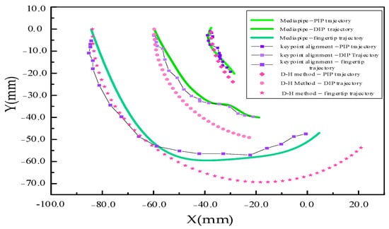
Figure 11.
Summary diagram of trajectories obtained by three measurement methods.
To demonstrate the performance differences of the three methods more intuitively, a comparison table was compiled based on the experimental methods presented in this paper. Detailed results are shown in Table 5.

Table 5.
The trajectory measurements based on the MediaPipe method compared to the other two methods.
Comprehensive analysis of the information in Figure 11 and Table 5: In the MAP project, the DH method has the largest difference in Fingertip, reaching 26.18% and, it also records the highest deviation in the Maximum Distance metric, at 17.32 mm. It can be seen from the image that the largest difference occurs mostly in the second half of the finger movement. It is reasonable to speculate that this may be due to the inability of the DH model to simulate the complex and smooth movements in the finger joints. Furthermore, as the finger’s motion progresses into its second half, more complex contact mechanics come into play, which the DH method struggles to effectively analyze.
The artificial keypoint alignment method is compared with the trajectory measurement based on the MediaPipe method. Both the values of MAPE and Maximum distance are the smallest, and it is found that the trajectories of the two are very close. This also verifies the accuracy and effectiveness of the trajectory measurement based on the MediaPipe method. However, for an average of 500 images, it takes nearly 200 min, which is too long and inefficient compared to the other two methods. By contrast, if you run the program directly, it takes only 5 s for the trajectory measurement based on the MediaPipe method to get the data.
We draw on the research strategy in Reference 21. By attaching angle sensors to the hands, information was obtained about the trajectory of finger movements [21]. Using the DIP and PIP perspectives, we construct a comparison of key parameters. It should be mentioned that due to the different degree of curvature of the selected gestures, there is a large difference in the value of the two, but the curve described by the two shows a highly consistent trend: that is, a gentle transition at the beginning, then a sharp rise, and a gradual trend again at the end of the movement. This finding not only validates the effectiveness of this experimental method in capturing finger motion dynamics, but also highlights its stability in the analysis of complex motion patterns.
In addition, the mathematical relationship between the MCP and PIP joints and the PIP and DIP joints under a gripping motion is introduced. As in Equation (9), x is the bending angle of the MCP joint and y is the bending angle of PIP joint, e is the bending time. As in Equation (10), u is the PIP bending angle and v is the DIP bending angle. The average accuracy is 87.6% and 88.3%, respectively. This result not only confirms the reliability of the experimental method, but also significantly improves the scientific rigor of the study and the credibility of the conclusions.
In summary, the trajectory measurement based on the MediaPipe method is a natural, efficient, and accurate finger multi-joint trajectory measurement method that can measure various finger joints in a non-contact state.
5. Finger Movement Trajectory and Analysis of Three Gestures
Experiments were then conducted on the palmar grasp, the pincer grasp and the straightening hand gestures selected above. The internal laws of gesture movement were analyzed and extracted through the tracking of hand joints, the angular acceleration of joint rotation and the angle of joint rotation.
5.1. Palmar Grasp
The palmar grasp is a common movement in our daily lives. The experiment simulated the state of grasping an object. It involves the flexibility of the PIP and DIP joints and the coordination of MCP joint. Figure 12 shows the joint motion trajectory, and Figure 13 presents the joint bending angle data.
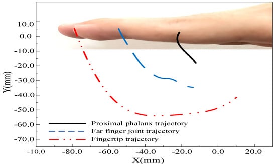
Figure 12.
Palmar Grasp of joint motion trajectory.
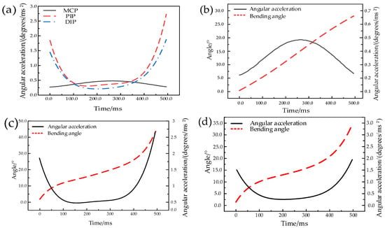
Figure 13.
Palmar grasp of joint bending angle data. (a) Curve of angular acceleration variation; (b) MCP angle and angular acceleration curve; (c) PIP angle and angular acceleration curve; (d) DIP angle and angular acceleration curve.
Regarding the MCP joint, the bending angle exhibits a linear growth trend, whereas the angular acceleration demonstrates a symmetrical evolution. Angular acceleration peaks at 250 ms before gradually decreasing on both sides. The PIP and DIP joints exhibit similar characteristics in their bending postures, albeit notable differences exist. In the initial phase, from 0 to 100 ms, the angular acceleration for both joints is relatively gentle, indicating a preparatory posture. During the mid-term period, from 100 to 350 ms, their bending processes show a stable acceleration trend, albeit with relatively mild acceleration. However, between 350 and 500 ms, both joints undergo a period of increasing acceleration, which may correlate with the final completion stage of the grasping action. In comparing the PIP and DIP joints, despite their similarities in bending posture, the PIP demonstrates a greater range of change in the bending degree, suggesting that it undertakes more bending tasks during the grasping process.
5.2. Pincer Grasp
The pincer grasp has high requirements for the coordination of the MCP and DIP joints. Figure 14 shows the joint motion trajectory, and Figure 15 shows the joint bending angle data.
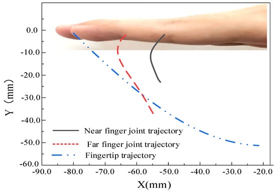
Figure 14.
Pincer Grasp of joint motion trajectory.
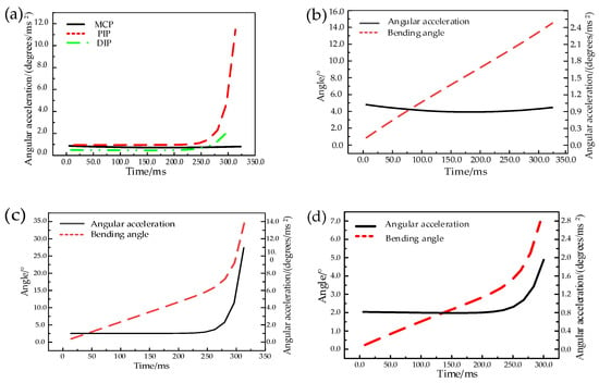
Figure 15.
Pincer grasp of joint bending angle data. (a) Curve of angular acceleration variation; (b) MCP angle and angular acceleration curve; (c) PIP angle and angular acceleration curve; (d) DIP angle and angular acceleration curve.
During the initial 0–250 ms, the angular acceleration of the three joints remains approximately constant at 0.9°/ms2. This phase can be regarded as the initial acceleration period of finger movement, marking the establishment of the initiation of motion and speed. Subsequently, from 250 to 320 ms, the accelerations of the PIP and DIP joints increase significantly, with PIP acceleration reaching as high as 10.0°/ms2. This transition signifies a smooth progression from the initial acceleration phase of finger movements to a more rapid completion stage, highlighting the high efficiency of the neuromuscular system in regulating fine motor activities.
5.3. The Straightening Posture
The straightening posture evolved from pushing and pulling movements. It emphasizes the up-drive movement of the MCP joint, and more fully exercises the DIP. Figure 16 illustrates the joint motion trajectory, and Figure 17 illustrates the joint bending angle data.
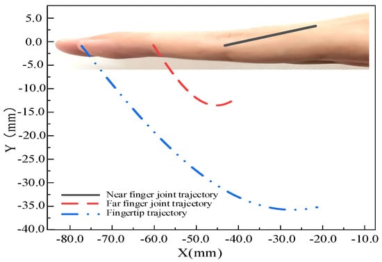
Figure 16.
The straightening posture of joint motion trajectory.
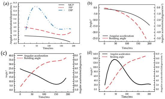
Figure 17.
The straightening posture of joint bending angle data. (a) Curve of angular acceleration variation; (b) MCP angle and angular acceleration curve; (c) PIP angle and angular acceleration curve; (d) DIP angle and angular acceleration curve.
A significant distinction from the previous two gestures is that the MCP movement is rear-driven, exhibiting negative values for both angular acceleration and bending angle, indicating a stretching motion rather than the traditional bending. Concurrently, this movement substantially engages the DIP, with the bending angle exceeding that of the proximal interphalangeal (PIP) joints, ultimately reaching a range of 60°. The changes in joint angular acceleration can be analyzed in three distinct stages. From 0 to 50 ms, the angular acceleration of the MCP and PIP joints decreases gradually, while the angular acceleration of the DIP joint rises to a peak value of 6°/ms2. From 50 to 140 ms, the angular acceleration of the DIP declines from this peak to approximately 1°/ms2, entering a stable bending phase. Between 140 and 200 ms, the angular acceleration of the DIP stabilizes, while the angular acceleration of the MCP decreases and that of the PIP increases, ultimately concluding in different states.
6. Conclusions
By comparing the DH method, the keypoint alignment method, and the trajectory measurement based on the MediaPipe method, this paper concludes that the trajectory measurement based on the MediaPipe method has high efficiency, a high recognition rate, and can perform local joint detection. The key parameter of time is also introduced by high-speed camera, which plays a great role in the analysis of joint motion.
The experimental results reveal that the PIP and DIP joints in the palmar grasp and the pincer grasp have very high cooperativity in both bending angle and angular acceleration. Notably, the maximum bending angle and maximum acceleration for both gestures originates from the PIP joint. However, for the straightening posture, not only are there no synergies between the bending angle and angular acceleration of the PIP and DIP joints, but the maximum bending angle and maximum acceleration are also 60° and 6°/ms2, respectively, and the maximum bending angle is also the largest of the three gestures.
Although human hand structures have commonalities, there are similarities and differences between different gestures, and the movement of the finger joints also has high complexity. This highlights the necessity of conducting in-depth research on each finger joint.
The primary limitation of the trajectory measurement utilizing the MediaPipe method is the high acquisition and maintenance costs associated with high-speed cameras, which inherently restricts the potential of this approach. To address this limitation, future research will focus on strategies aimed at reducing costs. Specifically, we want to train models that can recognize programs. The hope is that it will simulate or approximate the detailed information obtained by high-speed cameras, thereby replacing high-speed cameras with standard cameras. It is anticipated that this approach will significantly lower the cost threshold for experimental and practical applications, thereby facilitating the broader deployment and application of the technology across various scenarios and advancing the in-depth development of research and practice in related fields.
Author Contributions
Conceptualization, H.J. and S.L.; methodology, C.L. and P.Y.; validation, Y.C.; resources, Y.X. and X.H.; experiment, C.L. and Y.C.; writing, S.L. and C.L. All authors have read and agreed to the published version of the manuscript.
Funding
This research was funded by the Natural Science Foundation of Chongqing Municipality (CSTB2024NSCQ-MSX0143), Science and Technology Research Youth Project of Chongqing Municipal Education Commission (KJQN202301104), National Natural Science Foundation of China (No. 52375084), and Chongqing Municipal Science and Technology Commission Technology Innovation and Application Development Special Project (CSTB2022TIAD-KPX0076).
Data Availability Statement
The research simulation and experimental data of our paper can be reflected in the pictures and tables in the manuscript. Therefore, no new dataset link is established.
Acknowledgments
We thank Hu for his suggestions on revising the English style of this paper.
Conflicts of Interest
The authors declare that there are no conflicts of interest regarding the publication of this paper.
References
- Narumi, S.; Huang, X.; Lee, J.; Kambara, H.; Kang, Y.; Shin, D. A design of biomimetic prosthetic hand. Actuators 2022, 11, 167. [Google Scholar] [CrossRef]
- Tran, P.; Jeong, S.; Herrin, K.R.; Desai, J.P. Review: Hand exoskeleton systems, clinical rehabilitation practices, and future prospects. IEEE Trans. Med. Robot. Bionics 2021, 3, 606–622. [Google Scholar] [CrossRef]
- Liu, C.; Lu, J.; Yang, H.; Guo, K. Current state of robotics in hand rehabilitation after stroke: A systematic review. Appl. Sci. 2022, 12, 4540. [Google Scholar] [CrossRef]
- Wang, Y.; Li, Z.; Gu, H.; Yi, Z.; Yong, J.; Qi, Z.; Xingquan, Z.; Yilong, W.; Xin, Y.; Chunjuan, W.; et al. Chinese stroke report 2020 (Chinese Edition). Chin. J. Stroke 2022, 7, 433–447. [Google Scholar] [CrossRef]
- Xu, W.; Guo, Y.; Bravo, C.; Ben-Tzvi, P. Design, control and experimental evaluation of a novel robotic glove system for patients with brachial plexus injuries. IEEE Trans. Robot. 2023, 39, 1637–1652. [Google Scholar] [CrossRef] [PubMed]
- Ye, L.; Kalichman, L.; Spittle, A.; Dobson, F.; Bennell, K. Effects of rehabilitative interventions on pain, function and physical impairments in people with hand osteoarthritis: A systematic review. Arthritis Res. Ther. 2011, 13, R28. [Google Scholar] [CrossRef] [PubMed]
- Shi, D.; Zhang, W.; Zhang, W.; Ding, X. A review on lower limb rehabilitation exoskeleton robots. Chin. J. Mech. Eng. 2019, 32, 12–22. [Google Scholar] [CrossRef]
- Ozioko, O.; Dahiya, R. Smart tactile gloves for haptic interaction, communication and rehabilitation. Adv. Intell. Syst. 2022, 4, 2100091. [Google Scholar] [CrossRef]
- Zhu, Z.; Gao, S.; Wan, H.; Yang, W. Trajectory based grasp interaction for virtual environment. In Proceedings of the 24th International Conference on Advances in Computer Graphics, Hangzhou, China, 26–28 June 2006; Springer: Berlin/Heidelberg, Germany, 2006; pp. 300–311. [Google Scholar] [CrossRef]
- Ying, C.; Qingyun, M.; Hongliu, Y. Research progress of hand rehabilitation robot technology. Beijing Biomed. Eng. 2018, 37, 650–656. [Google Scholar] [CrossRef]
- Gao, Y.; Fang, L.; Jiang, X.; Gong, Y. Research on a precision synthesis method for a 7-degree-of-freedom Robotic Arm Mechanism Based on D-H Parameters. J. Instrum. Meter 2022, 43, 137–145. [Google Scholar] [CrossRef]
- Park, C.B.; Park, H.S. Portable 3D-printed hand orthosis with spatial stiffness distribution personalized for assisting grasping in daily living. Front. Bioeng. Biotechnol. 2023, 11, 895745. [Google Scholar] [CrossRef] [PubMed]
- Wang, H.; Zhao, C.K.; Ji, Y.Q. Emulation of kinematic trajectory of fingertip. J. Northeast. Univ. (Nat. Sci.) 2006, 27, 891–894. (In Chinese) [Google Scholar]
- Yu, J.; Yan, J.; Xiao, J. Establishment and verification of finger joint kinematic model based on the combination of medical and engineering. J. Mech. Eng. 2024, 1–11. (In Chinese) [Google Scholar]
- Zhang, F.; Bazarevsky, V.; Vakunov, A.; Tkachenka, A.; Sung, G.; Chang, C.-L.; Grundmann, M. MediaPipe hand: On-device real-time hand tracking. arXiv 2020, arXiv:2006.10214. doi.10.48550/arXiv.2006, 10214. [Google Scholar]
- Güney, G.; Jansen, T.S.; Dill, S.; Schulz, J.B.; Dafotakis, M.; Antink, C.H.; Braczynski, A.K. Video-Based hand movement analysis of parkinson patients before and after medication using high-frame-rate videos and MediaPipe. Sensors 2022, 22, 7992. [Google Scholar] [CrossRef]
- Mohd, M.N.H.; Asaari, M.S.M.; Ping, O.L.; Rosdi, B.A. Vision-Based hand detection and tracking using fusion of kernelized correlation filter and single-shot detection. Appl. Sci. 2023, 13, 7433. [Google Scholar] [CrossRef]
- Sanalohit, J.; Katanyukul, T. TFS recognition: Investigating MPH thai finger spelling recognition: Investigation MediaPipe hands potentials. arXiv 2022, arXiv:2201.03170. [Google Scholar]
- Kokubu, S.; Wang, Y.; Vinocour, P.E.T.; Lu, Y.; Huang, S.; Nishimura, R.; Hsueh, Y.-H.; Yu, W. Evaluation of fiber-reinforced modular soft actuators for individualized soft rehabilitat ion gloves. Actuators 2022, 11, 84. [Google Scholar] [CrossRef]
- MontJohnson, A.; Cronce, A.; Qiu, Q.; Patel, J.; Eriksson, M.; Merians, A.; Adamovich, S.; Fluet, G. Laboratory-Based Examination of the Reliability and Validity of Kinematic Measures of Wrist and Finger Function Collected by a Telerehabilitation System in Persons with Chronic Stroke. Sensors 2023, 23, 2656. [Google Scholar] [CrossRef]
- Yang, J.; Xie, H.; Shi, J. A novel motion-coupling design for a jointless tendon-driven finger exoskeleton for rehabilitation. Mech. Mach. Theory 2016, 99, 83–102. [Google Scholar] [CrossRef]
- Kim, H.; Jang, S.; Do, P.T.; Lee, C.K.; Ahn, B.; Kwon, S.; Chang, H.; Kim, Y. Development of wearable finger prosthesis with pneumatic actuator for patients with partial amputations. Actuators 2023, 12, 434. [Google Scholar] [CrossRef]
- Ni, C. Rehabilitation treatment for stroke at different stages of recovery. Anhui Med. 2009, 30, 1377–1378. [Google Scholar] [CrossRef]
Disclaimer/Publisher’s Note: The statements, opinions and data contained in all publications are solely those of the individual author(s) and contributor(s) and not of MDPI and/or the editor(s). MDPI and/or the editor(s) disclaim responsibility for any injury to people or property resulting from any ideas, methods, instructions or products referred to in the content. |
© 2024 by the authors. Licensee MDPI, Basel, Switzerland. This article is an open access article distributed under the terms and conditions of the Creative Commons Attribution (CC BY) license (https://creativecommons.org/licenses/by/4.0/).