Article

Optimal Searching-Based Reference Current Computation Algorithm for IPMSM Drives Considering Iron Loss

by
Péter Stumpf
*,† and
Tamás Tóth-Katona
Department of Automation and Applied Informatics, Budapest University of Technology and Economics, Műegyetem rkp. 3., H-1111 Budapest, Hungary
*
Author to whom correspondence should be addressed.
These authors contributed equally to this work.
Actuators 2024, 13(8), 321; https://doi.org/10.3390/act13080321
Submission received: 29 June 2024 / Revised: 19 August 2024 / Accepted: 20 August 2024 / Published: 21 August 2024
(This article belongs to the Section High Torque/Power Density Actuators)

Abstract

:
Interior permanent magnet synchronous machines (IPMSMs) are widely used as traction motors in the electric drive-train because of their high torque-per-ampere characteristics and potential for wide field weakening operation to expand the constant power range. The paper aims to introduce the most important equations to calculate the operating trajectories of an IPMSM for optimal control. The main contribution is that the optimal operating trajectories are calculated by a feedforward, Newton–Raphson method-based searching algorithm that considers the iron loss resistance of IPMSMs. Steady-state calculations and dynamic simulation results prove the theoretical findings.

1. Introduction

Global trends in the electrification of drivelines forecast the drastic increase in mild-hybrid and full-electric vehicles (EVs) as well as micro-mobility vehicles on the road. Permanent magnet synchronous machines (PMSMs) dominate in these applications, although the share of induction machines and synchronous reluctance machines is also increasing, thanks to their attractive features such as high power density and efficiency, torque-to-weight ratio, maturity, and robustness [1]. Internal/interior PMSMs (IPMSMs) also provide the possibility for wide speed operation, which is an important factor for EVs [2].
In the scientific literature, several different control approaches are found for IPMSMs, such as direct torque control (DTC) or model predictive control (MPC). Nonetheless, field-oriented control is still considered a standard method in industrial applications. For the optimal control performance, the reference d and q axis currents should be determined based on the actual operating region of the machine, defined by the actual mechanical speed and torque of the machine. Traditionally, four operating regions can be distinguished: maximum torque per current or ampere (MTPC or MTPA), maximum current (MC), field weakening (FW), and maximum torque per voltage (MTPV). Some papers consider other operating trajectories as well, such as maximum torque per loss (MTPL) [3] or maximum torque per flux (MTPF) [4]. If the machine speed is lower than its base speed, the machine follows the MTPC trajectory. If the machine speed is higher than the base speed, in the FW region, great attention must be paid to the fact that the drive can work on the voltage and/or current limit. If the current reference signals are not properly chosen, the machine will not be able to track them, which can deteriorate the performance of the drive and can cause stability issues. Paper [1] provides a detailed review of the commonly used approaches for FW operation of IPMSMs in EV applications.
Reference current calculation algorithms can be classified according to several aspects. The current paper proposes a so-called feedforward technique. In this case, an outer speed loop dictates the reference torque of the machine, from which the d and q axis reference currents are determined using the actual mechanical speed of the drive. One form of the implementation of the feedforward technique is when analytical expressions are used to directly calculate the reference current. Paper [5] utilizes Ferrari’s method to solve quartic equations, which formulates the optimal current reference values. A unified theory for analytically computing reference current for IPMSMs considering the effect of stator resistance is introduced in [4]. The same concept is expanded to consider iron loss in [3]. Paper [6] derives explicit formulas for the calculation of current trajectory and proposes a feedforward controller that has a low computational cost and can be easily implemented in real time. Another type of feedforward technique is the searching method based on trajectory tracking, which is most commonly researched today due to an increase in the computing power of embedded devices. In this case, the algorithm calculates intersections of constraint equations to find the most efficient reference currents. Most commonly, gradient-based methods are utilized, which converge rapidly to the solution [7,8,9]. Paper [7] proposes a second-order Newton–Raphson method to numerically solve the trajectory intersection equations. The Newton method is also utilized in [9]. In the case of applying analytical equations and in searching-based methods, a problem arises if the machine parameters change during operation, which can deteriorate the performance of the algorithms. Modeling issues regarding parameter variations can be addressed either by using look-up tables (LUTs) obtained from experimental results or by finite element analysis [7] or curve fitting methods using polynomial approximation [10] or online parameter estimation [11].
Typically, the effect of iron loss is neglected in reference current calculation algorithms. However, a more precise algorithm with the ability to consider the effect of iron loss can benefit greatly by controlling the machine. It is even true for applications, where the iron loss is not negligible, as in IPMSMs with high operating electrical frequencies [12,13] or in machines utilizing a special core design with advanced magnetic materials, where the iron loss can be more dominant than even copper loss [14]. Paper [15] offers a comprehensive overview of the different equivalent circuit models of IPMSM considering iron loss. Traditionally, the effect of iron loss is taken into account by resistances parallel to the magnetizing branches, with the frequency-dependent value in the d and q axis equivalent to the circuits of the machine [16,17,18] (see Figure 1). A loss minimization control method for IPMSMs utilizing the traditional circuit model and considering self-saturation and cross saturation is introduced in [17]. A similar circuit model is used in [18], where a dynamic optimization strategy for model predictive control is introduced. The proposed scheme accounts for inverter losses as well. Paper [19] poses a simplified loss minimization control method by using a virtual current signal and considering iron loss resistance. Paper [20] presents an improved circuit model for the model predictive direct torque control of IPMSMs. A circuit model incorporating the effect of harmonic iron loss caused primarily by inverter sideband harmonics is introduced in [21].
To consider and model the effect of iron loss, its value should be estimated from analytical methods, finite element analysis, or experimental tests. Paper [22] provides the specific laboratory equipment as well as a test method for measuring iron loss of PMSMs at different operating speeds and temperatures. A more general method of measuring iron loss under real operating conditions is introduced in [23]. A particle swarm optimization-based method, which considers high-order harmonics, rotating magnetization, and temperature factors, is introduced to estimate the iron loss in [24]. Paper [25] presents an iron loss estimation method from finite element analysis. The method considers the interaction effect of the multi-physics factors and is verified by experimental tests as well.
The main goal of this manuscript is to propose a feedforward Newton–Raphson method-based searching algorithm that considers iron loss resistance of IPMSMs. The method is utilized for the MTPA, MC, FW, and MTPV regions. Steady-state calculations and dynamic simulation results prove the theoretical findings.
The paper is organized as follows. The subsequent section lays down the theoretical background. This is followed by the description of the reference current calculation algorithm. Steady-state results and a simulation study are presented in Section 4. Finally, the conclusions can be found in Section 5.

2. Theoretical Background

The following section introduces the machine model, incorporating iron loss, the equations of the voltage and current constraints, the closed loop control scheme, and the basis of the Newton–Raphson method.

2.1. IPMSM Mathematical Model with Iron Loss

Typically, IPMSMs are modeled in the d q rotating coordinate system, where the vector of the pole flux is aligned with the d axis. The voltage balance of the IPMSM in the d q reference frame, in accordance with Figure 1, can be expressed as follows:
v d = R s i d 1 + L d d i d d t ω 1 L q i q = R s i d + k i L d d i d d t ω 1 L q i q , v q = R s i q 1 + L q d i q d t + ω 1 L d i d + ω 1 Ψ PM = R s i q + k i L q d i q d t + ω 1 L d i d + ω 1 Ψ PM ,
where R s is the stator resistance; L d and L q are the d and q axis inductance of the machine, respectively; Ψ PM is the amplitude of the flux induced by the permanent magnets of the rotor in the stator phases; ω 1 = n P Ω m is the electrical angular frequency; Ω m is the mechanical angular speed; n P is the number of pole pairs; and k i = 1 + R s / R i . Furthermore, i d 1 = i d + i di and i q 1 = i q + i qi , where i di and i qi are the d and q axis current through resistance R i , expressing the iron loss of the machine.
In steady-state i di and i qi current components can be expressed as follows:
i di = ω 1 L q i q R i = k q ω 1 i q and i qi = ω 1 ( L d i d + Ψ PM ) R i = k d ω 1 i d + k PM ω 1 ,
where the constants k d , k q , and k PM can be given as follows:
k d = L d R i , k q = L q R i , k PM = Ψ PM R i .
The M electric torque of the machine can be expressed as follows:
M = 3 2 n P i q ( Ψ PM + Δ L i d ) ,
where Δ L = L d L q .

2.2. Voltage and Current Constraints of the IPMSM Machine Drive

In the case of an electric drive, current and voltage constraints (represented by I 1 , max and V 1 , max ) must be taken into account.
The voltage constraint of an IPMSM for operating the voltage source inverter (VSI) feeding the machine in the linear modulation range can be formulated as follows:
v d 2 + v q 2 = V 1 V 1 , max = V DC 3 ,
where V 1 denotes the momentary amplitude of the stator voltage, and V DC is the DC bus voltage of the VSI.
The square of momentary amplitude of the stator voltage V 1 2 = v d 2 + v q 2 should be expressed with the help of i d and i q current components to calculate the optimal working trajectories (see Section 3). By using (1), the following expression can be derived for the steady state:
v d 2 + v q 2 = ( R s 2 + k 1 ω 1 2 ) i d 2 + k 2 ω 1 2 i d + k 3 ω 1 i d i q + ( R s 2 + k 4 ω 1 2 ) i q * 2 + k 5 ω 1 i q + k 6 ω 1 2 ,
where the constants k 1 k 6 can be given as follows:
k 1 = L d 2 k i 2 , k 2 = 2 L d Ψ PM k i 2 , k 3 = 2 Δ L R s k i , k 4 = L q 2 k i 2 , k 5 = 2 R s k i Ψ PM , k 6 = k i 2 Ψ PM 2 .
The current constraint of the machine can be formulated as follows:
i d 1 2 + i q 1 2 = I 1 I max ,
where I 1 denotes the momentary amplitude of the stator current, and I max is the maximum allowable current of the drive system. The maximum stator current is bounded by either the motor or the VSI maximum current. This means that I max = min ( I max , VSI , I max , IPMSM ) , where I max , VSI is the maximal allowable VSI current, and I max , IPMSM is the maximal allowable motor current. The current constraint should also be expressed with the help of i d and i q current components to calculate the optimal working trajectories. By using (2), the following expression can be derived for i d 1 and i q 1 :
i d 1 2 = ( i d + i di ) 2 = i d 2 + k q 2 ω 1 2 i q 2 2 k q ω 1 i d i q , i q 1 2 = ( i q + i qi ) 2 = i q 2 + k d 2 ω 1 2 i d 2 + k PM 2 ω 1 2 + 2 k PM k d ω 1 2 i d + 2 k d ω 1 i d i q + 2 k PM ω 1 i q .

2.3. Operation Regions of an IPMSM

To represent the operation regions of an IPMSM, a widely used approach is to present the working points of the machine on the i d 1 i q 1 plane (see Figure 2).
In such a plane, the constant current loci are circles, and the constant torque loci are hyperbolas. The voltage ellipses illustrate the maximum voltage the machine may utilize in the given working point. The machine should be operated in a working point, which is inside the determined boundaries of the current limit and the voltage limit. As mentioned previously, the operating regions of an IPMSM can be divided in to four regions: maximum torque per current (MTPC), field weakening (FW), maximum current (MC), and maximum torque per voltage (MTPV). The boundaries of these operation regions can be defined via the characteristic speeds of an IPMSM, namely, the base speed Ω m , b , the boundary speed Ω m , 0 , and the critical speed Ω m , cr . Table 1 describes these characteristic speeds in brief, and Section 3 details them. Furthermore, the calculation methods for the base and the critical speed are detailed in Appendix B.

2.4. Control Scheme

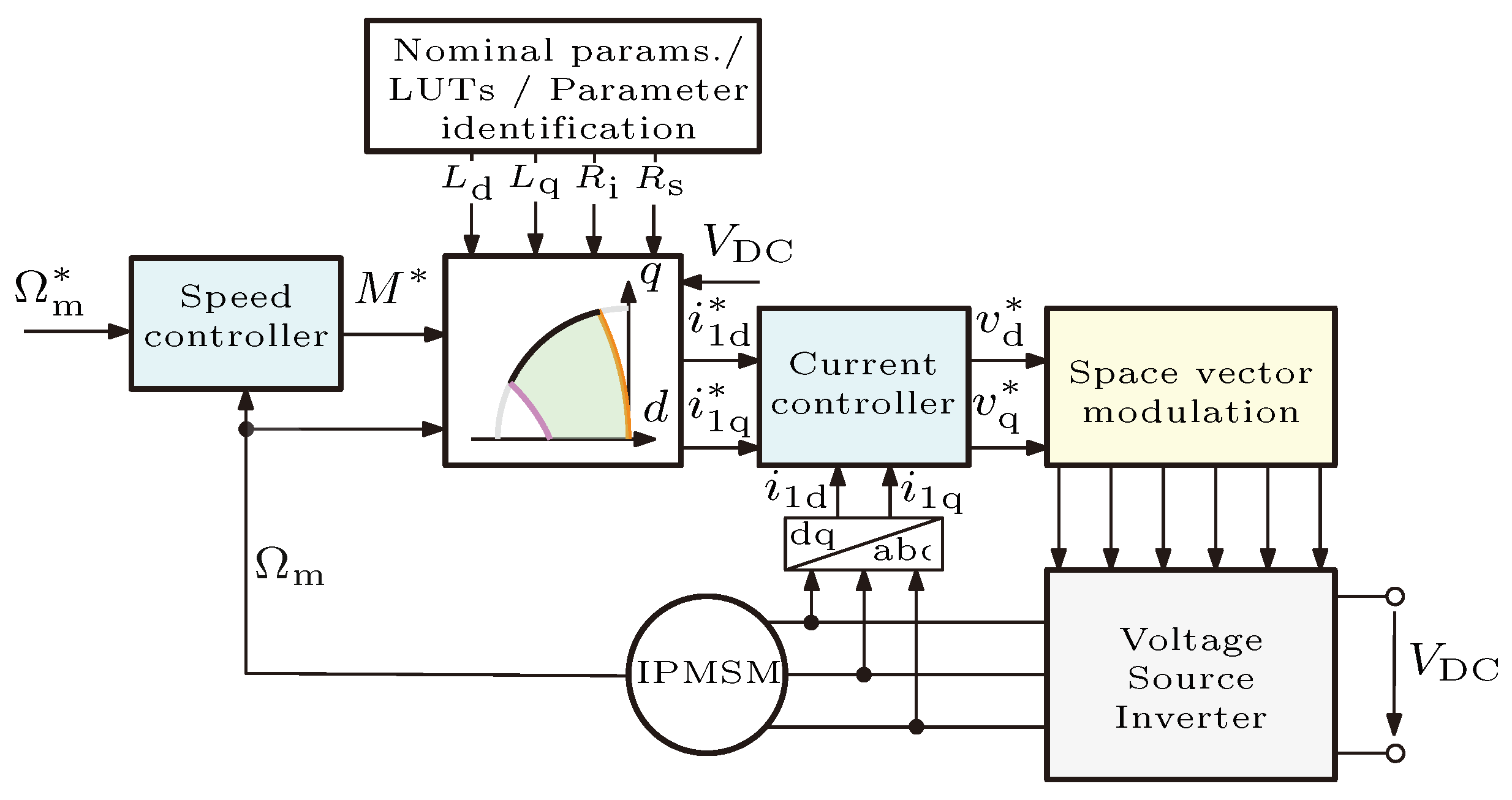
The control scheme of an IPMSM is shown in Figure 3. The figure shows two closed feedback loops. One is a speed control loop, which outputs the reference torque ( M * ) for the machine to force the actual mechanical speed Ω m to track its Ω m * reference signal. The reference torque and the measured angular speed is passed to the current reference-generating function. For current reference calculation, the machine parameters can be assumed to be constant and can also be passed to the function from the LUT or a parameter identification method. The LUT can be generated using FEM or measurement results. Using these input parameters, the current reference-generating algorithm calculates the appropriate reference currents i d 1 * and i q 1 * for the desired working point. It should be noted that the current reference-generating algorithm takes into account the voltage (4) and current constraints (6).
After completing the necessary calculations, the current reference values are passed to the second, inner current control loops. In the current controllers, the traditionally used decoupling is found, and PI-type controllers regulate the d and q axis voltage reference signals v d * and v q * to the VSI through the space vector modulation unit, which produces the gate signals for the VSI.
It should be noted that Figure 3 provides a simplified block diagram of the drive system. Typically, depending on the application, additional measurements (e.g., temperature) are also required to implement protection and/or diagnostic functions. For example, a potential problem can be the demagnetization of the IPMSM. Commonly, to avoid demagnetization, the temperature of the machine is monitored. If the machine temperature exceeds a certain threshold, then the losses of the machine must be reduced. One possibility is to lower the I m a x maximum allowable current of the drive, as it significantly reduces conduction loss as well as iron loss. It should be noted this would not change the general logic and usability of the proposed reference current calculation scheme introduced in the paper.

2.5. Basis of the Newton–Raphson Method

In this paper, a Newton–Raphson (NR)-based method will be utilized to obtain the optimal reference currents as the intersections of nonlinear equations. The general multidimensional NR method can be written by solving the following set of functions for zero:
f 1 ( x 1 , , x n ) f 2 ( x 1 , , x n ) f n ( x 1 , , x n ) = f ( x ) = 0 .
The functions are solved for x R n and f ( x ) R n , where n stands for the number of differentiable but possibly nonlinear equations. The NR method is an iterative algorithm, meaning that, after a given approximation of the solution at step k, in the next k + 1 step, we wish to have a more accurate approximation. This is done by using the Taylor-expanding f function around the t = k time instant to some degree of order. The Taylor series in time can be written as follows:
f ( k ) + f ( k ) 1 ( t k ) + f ( k ) 2 ( t k ) 2 + = n = 1 f ( n ) ( k ) n ! ( t k ) n .
By assuming n = 2 (equations will be solved for i d * and i q * reference current components) and taking the Taylor expansion (9) until the second element and implementing it for the current equations, we obtain the following:
i d * ( k + 1 ) i q * ( k + 1 ) = i d * ( k ) i q * ( k ) J 1 | i d * = i d * ( k ) i q * = i q * ( k ) f 1 ( i d * ( k ) , i q * ( k ) ) f 2 ( i d * ( k ) , i q * ( k ) ) ,
where f 1 ( i d * ( k ) , i q * ( k ) ) and f 2 ( i d * ( k ) , i q * ( k ) ) are functions dependent on the operating region of the IPMSM. These functions will be introduced and discussed in Section 3.
The Jacobian matrix can be given as follows:
J | i d * = i d * ( k ) i q * = i d * ( k ) = f 1 ( i d * , i q * ) i d * f 1 ( i d * , i q * ) i q * f 2 ( i d * , i q * ) i d * f 2 ( i d * , i q * ) i q * = f 1 i d ( k ) f 1 i q ( k ) f 2 i d ( k ) f 2 i q ( k ) .
If the inverse of the Jacobian matrix given in (11) is substituted into (10), we will have the following iterative set of equations [7]:
i d * ( k + 1 ) = i d * ( k ) + f 2 i q ( k ) f 1 ( i d * ( k ) , i q * ( k ) ) f 1 i q ( k ) f 2 ( i d * ( k ) , i q * ( k ) ) f 2 i d ( k ) f 1 i q ( k ) f 1 i d ( k ) f 2 i q ( k ) , i q * ( k + 1 ) = i q * ( k ) + f 1 i d ( k ) f 2 ( i d * ( k ) , i q * ( k ) ) f 2 i d ( k ) f 1 ( i d * ( k ) , i q * ( k ) ) f 2 i d ( k ) f 1 i q ( k ) f 1 i d ( k ) f 2 i q ( k ) .
This process is repeated until the geometric distance of the two iteration results is very small:
i d * ( k + 1 ) i d * ( k ) 2 + i q * ( k + 1 ) i q * ( k ) 2 < ε ,
where ε is defined as current setting precision, or where the number of iterations exceeds a predefined k max number. In the latter case, the solution is not converging, and the searching algorithm has to be reinitialized.

3. Current Reference-Generating Algorithm

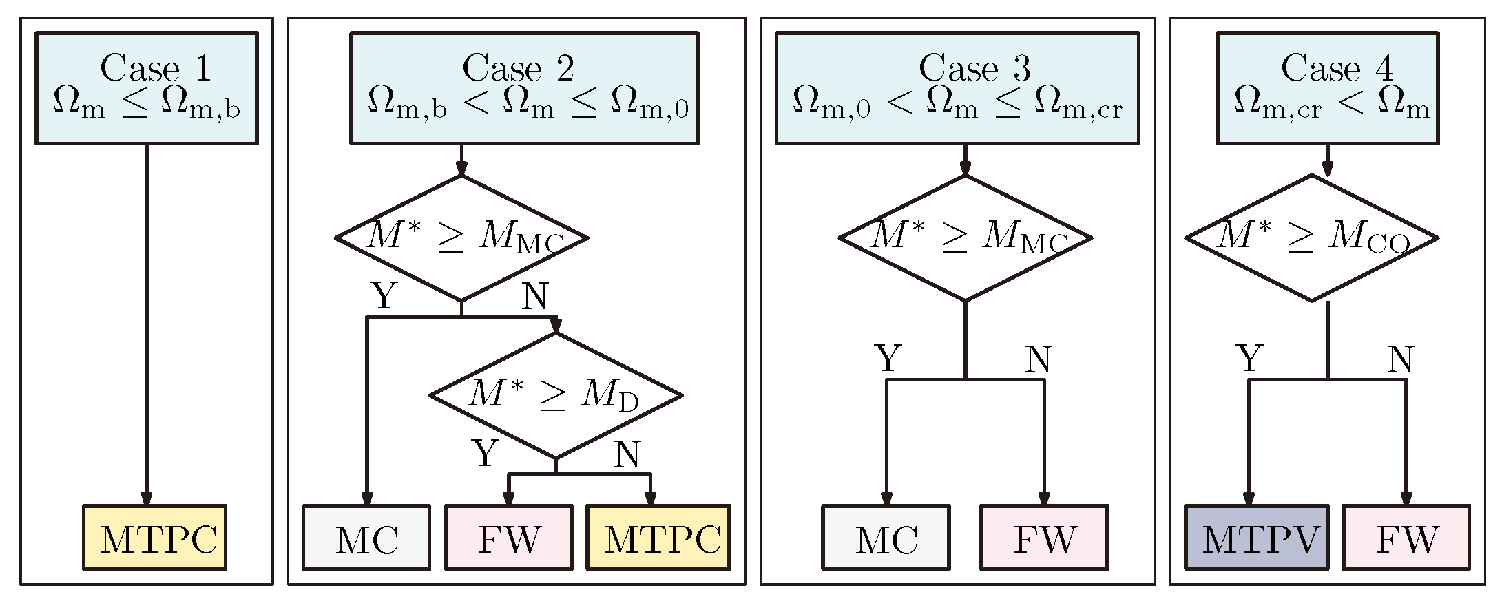
As discussed previously, depending on the reference torque and the actual mechanical speed, four different operating modes can be selected (MTPC, MC, FW, MTPV). An operating mode selector algorithm having four cases (see Figure 4) provides the right mode to calculate the reference currents. It should be noted that the flowchart given in Figure 4 is valid, assuming that Ω m , b < Ω m , 0 < Ω m , cr . At the end of the section, it is mentioned how the mode selector algorithm is changed if this is not the case.
In the following, the equations are expressed for the reference current components i d * and i q * . However, the actual reference stator current components, which are the input signals of the current controllers (see Figure 3), can be calculated in accordance with (2) as follows:
i d 1 * = i d * k q ω 1 i q * and i q 1 * = i q * + k d ω 1 i d * + k PM ω 1 .

3.1. Case 1: Ω m Ω m , b

When the IPMSM’s mechanical speed is lower than the base speed ( Ω m Ω b ) , the MTPC region is utilized, as shown in Figure 4 (also see the O A curve in Figure 2). The MTPC strategy aims to minimize copper losses in the constant torque region. The problem statement can be written in mathematical form as follows:
min . R s ( i d 1 * 2 + i q 1 * 2 ) s . t . M * = 3 2 n P i q * ( Ψ PM + Δ L i d * ) .
In this paper, the Lagrange multiplier approach is applied to obtain the solution in the following form:
H 1 ( i d * , i q * , λ 1 ) = R s ( i d 1 * 2 + i q 1 * 2 ) + λ 1 M * 3 2 n P i q * ( Ψ PM + Δ L i d * ) .
By substituting (7) into the equation, the partial derivatives can be calculated as follows:
H 1 i d * = 2 R s ( 1 + k d 2 ω 1 2 ) i d * + 2 R s ( k d k q ) ω 1 i q * + 2 R s k PM k d ω 1 2 λ 1 3 2 n P Δ L i q * = 0 , H 1 i q * = 2 R s ( 1 + k q 2 ω 1 2 ) i q * + 2 R s ( k d k q ) ω 1 i d * + 2 R s k P M ω 1 λ 1 3 2 n P Ψ P M λ 1 3 2 n P Δ L i d * = 0 , H 1 λ 1 = M * 3 2 n P i q ( Ψ PM + Δ L i d * ) = 0 .
Solving the first two equations in (17) by eliminating the parameter λ 1 , the MTPC relationship for i d * and i q * can be expressed as f 2 , MTPC . In (18), the two equations used for the Newton–Raphson iteration to calculate optimal i d * and i q * current reference components can be found:
f 1 , MTPC = M * 3 2 n P i q * ( Ψ PM + Δ L i d * ) = 0 , f 2 , MTPC = 2 R s ( 1 + k q 2 ω 1 2 ) i q * 2 2 R s ( 1 + k d 2 ω 1 2 ) i d * 2 + k s k d ω 1 2 k s ( 1 + k d 2 ω 1 2 ) k d k q i d * k s k d Ψ PM ω 1 2 Δ L = 0 ,
where k s = 2 R s k P M .
The Jacobian matrix for the NR calculation can be found in the Appendix A (A1).

3.2. Case 2: Ω m , b < Ω m Ω m , 0

If the mechanical speed Ω m is equal to the base speed Ω m , b of the IPMSM, then the voltage constraint ellipse shrinks to intersect point A (see Figure 2). The value of Ω m , b is determined by d and q axis currents at the intersection point of the current limit circle, the voltage ellipse, and the MTPC curve, via (1) and (4). Above the mechanical speed of Ω m , 0 , more negative d axis current is needed to make the current reference move along the MC circle (see the A G curve in Figure 2). By operating the machine along the MC curve, both the voltage (see (4) and (5)) and the current constraint (see (6) and (7)) should be fulfilled at the same time. The following relationship can be derived for i d * and i q * reference currents for the MC trajectory:
f 1 , MC = i d 1 * 2 + i q 1 * 2 I max * 2 = 0 = ( 1 + k d 2 ω 1 2 ) i d * 2 + ( 1 + k q 2 ω 1 2 ) i q * 2 + 2 k P M k d ω 1 2 i d * + 2 k P M ω 1 i q * + 2 ω 1 ( k d k q ) i d * i q * + k P M 2 ω 1 2 I max 2 = 0 , f 2 , MC = v d 2 + v q 2 V DC 2 3 = 0 = ( R s 2 + k 1 ω 1 2 ) i d * 2 + k 2 ω 1 2 i d * + k 3 ω 1 i d * i q * + ( R s 2 + k 4 ω 1 2 ) i q * 2 + k 5 ω 1 i q * + k 6 ω 1 2 V DC 2 3 = 0 .
The Jacobian matrix of the MC trajectory for the NR calculation can be found in the Appendix A (A2).
The achievable torque value ( M MC ) belonging to this operating mode can be calculated in real time by substituting the calculated i d * and i q * current components into (3). If the difference between the actual mechanical speed and its reference signal is large, the speed controller saturates and may output the maximum allowable reference torque, which may be larger than or equal to the achievable electric torque M MC in this region (see point B in Figure 2). In this case, the current controllers receive the reference signals i d 1 * and i q 1 * calculated from (19) (see the left branch for Case 2 in Figure 4).
As the actual mechanical speed approaches the reference value, the speed controller starts to reduce the value of the reference torque below M MC , and the reference current set point moves along a voltage ellipse curve in the FW region (see the B C curve in Figure 2). In this case, current reference points can be calculated as the intersection point of the torque hyperbola and the voltage constraint:
f 1 , FW = M * 3 2 n P i q * ( Ψ PM + Δ L i d * ) = 0 , f 2 , FW = ( R s 2 + k 1 ω 1 2 ) i d * 2 + k 2 ω 1 2 i d * + k 3 ω 1 i d * i q * + ( R s 2 + k 4 ω 1 2 ) i q * 2 + k 5 ω 1 i q * + k 6 ω 1 2 V DC 2 3 = 0 .
The Jacobian matrix of FW for the NR calculation can be found in the Appendix A (A3).
The voltage constraint ellipse at a given electrical angular frequency intersects with the MTPC curve (see point C in Figure 2). The M D torque value at this intersection point can be calculated from (3) by determining the i d * and i q * values from the voltage constraint equation (see f 2 , FW ) and the equation of the MTPC curve (see f 2 , MTPC ). If the reference torque is smaller than this M D value, the current reference set point can be calculated from (18) (see point D in Figure 2 and see the left branch for Case 2 in Figure 4).
As mentioned previously, the value of Ω m , b can be determined by the intersection point of the current limit circle, the voltage ellipse, and the MTPC curve. This means that, f 2 , MTPC , f 1 , MC , and f 2 , MC must be fulfilled simultaneously. In this case, there are actually three state variables ( i d * , i q * , and ω 1 = Ω m n p ). The NR method introduced in Section 2.5 can also be used in this case, with the difference being that the Jacobian matrix will be a 3 × 3 matrix, and the partial derivations must be performed with respect to i d * , i q * , and ω 1 as well. A more detailed description of the calculation of base speed can be found in Appendix B.
This second region (Case 2 in Figure 4) is valid until the mechanical speed Ω m 0 . At this speed value, the voltage ellipse intersects the MTPC curve at the origo (see Figure 2). Mechanical speed Ω m 0 can be calculated as follows:
Ω m , 0 = V DC k i Ψ PM n p .

3.3. Case 3: Ω m 0 < Ω m Ω m , cr

When the mechanical speed exceeds Ω m 0 and M * M MC , the IPMSM operates along the MC circle, where M MC is calculated in real time by substituting the i d * and i q * current references into Equation (3). For example, see point E in Figure 2 and the left branch for Case 3 in Figure 4. If the reference torque is smaller than the calculated limit torque M * < M MC , then the machine operates along a voltage ellipse; see point F in Figure 2 and the right branch for Case 3 in Figure 4. Depending on which side branch is then selected, the equations given in (19) or (20) should be used to calculate the reference currents.

3.4. Case 4: Ω m , cr < Ω m

When the mechanical speed is higher than Ω m , cr the motor enters into the so-called MTPV region (see Figure 2). The value of the critical speed Ω m , cr can be determined by the intersection point of the current limit circle, the voltage ellipse, and the MTPV curve. Above mechanical speed Ω m , cr , the d axis reference current should be increased to move the working point along the MTPV curve (see the GH curve in Figure 2).
The MTPV solution can be formulated by maximizing the electric torque and, at the same time, maintaining the voltage constraint:
max . 3 2 n P i q * ( Ψ PM + Δ L i d * ) s . t . V DC 2 3 = v d 2 + v q 2 .
The Lagrange multiplier approach can be utilized to obtain the solution for the MTPV trajectory. The Lagrange function can be given as follows:
H 2 ( i d * , i q * , λ 2 ) = 3 2 n P i q * ( Ψ PM + Δ L i d * ) + λ 2 ( ( R s 2 + k 1 ω 1 2 ) i d * 2 + k 2 ω 1 2 i d * + k 3 ω 1 i d * i q * + ( R s 2 + k 4 ω 1 2 ) i q * 2 + k 5 ω 1 i q * + k 6 ω 1 2 V DC 2 3 ) .
The partial derivatives can be expressed as follows:
H 2 i d * = 3 2 n P Δ L i q * + 2 λ 2 ( R s 2 + k 1 ω 1 2 ) i d * + λ 2 k 2 ω 1 2 + λ 2 k 3 ω 1 i q * = 0 , H 2 i q * = 3 2 n P Δ L Ψ PM + 3 2 n P Δ L i d * + 2 λ 2 ( R s 2 + k 4 ω 1 2 ) i q * + λ 2 k 5 ω 1 + λ 2 k 3 ω 1 i d * = 0 , H 2 λ 2 = ( R s 2 + k 1 ω 1 2 ) i d * 2 + k 2 ω 1 2 i d * + k 3 ω 1 i d * i q * + ( R s 2 + k 4 ω 1 2 ) i q * 2 + k 5 ω 1 i q * + k 6 ω 1 2 V DC 2 3 = 0 .
Solving the first two equations in (24) by eliminating the parameter λ 2 , the MTPV relationship for i d * and i q * can be expressed as follows:
f 1 , MTPV = ( R s 2 + k 1 ω 1 2 ) i d * 2 + k 2 ω 1 2 i d * + k 3 ω 1 i d * i q * + ( R s 2 + k 4 ω 1 2 ) i q * 2 + k 5 ω 1 i q * + k 6 ω 1 2 V DC 2 3 = 0 , f 2 , MTPV = 2 Δ L R s 2 + k 1 ω 1 2 i d * 2 + 2 Δ L R s 2 + k 4 ω 1 2 i q * 2 2 Ψ PM ( R s 2 + k 1 ω 1 2 ) + Δ L k 2 ω 1 2 i d * + ( Δ L k 5 ω 1 Ψ P M k 3 ω 1 ) i q * k 2 Ψ PM ω 1 2 = 0 .
The Jacobian matrix of MTPV for the NR calculation can be found in the Appendix A (A4).
If an ideal IPMSM with zero stator resistance ( R s = 0 ) and infinitely large iron loss resistance ( k i = 1 ) is assumed, f 2 , MTPV simplifies to the following form:
f 2 , MTPV | R s = 0 k i = 1 = L d 2 Δ L i d * 2 + L q 2 Δ L i q * 2 L d 2 Ψ PM i d * Δ L L d Ψ PM i d * L d Ψ PM 2 = 0 ,
which is well-known in the literature and was also introduced in paper [7].
The achievable torque, the so-called cutoff torque M CO , belonging to the MTPV curve can be calculated in real time by substituting the calculated i d * and i q * current components into (3). If the reference torque is greater than or equal to this M CO value, the current reference set point can be found on the MTPV curve (see point H in Figure 2 and see the left branch for Case 4 in Figure 4). If the reference torque is smaller than the so-called cutoff torque M CO , which belongs to the current set points at the crossing of the MTPV locus with the voltage ellipse at a given mechanical speed, the machine works in the FW region, and the equations given in (20) can be used to calculate the reference currents (see point J in Figure 2 and the right branch for Case 4 in Figure 4).
As mentioned previously, the value of Ω m , cr can be determined by the intersection point of the current limit circle, the voltage ellipse, and the MTPV curve. This means that f 1 , MTPV , f 2 , MTPV , and f 1 , MC must be fulfilled simultaneously. In this case, there are actually three state variables ( i d * , i q * , and ω 1 = Ω m n p ). The NR method introduced in Section 2.5 can also be used in this case, with the difference being that the Jacobian matrix will be a 3 × 3 matrix, and the partial derivations must be performed with respect to i d * , i q * , and ω 1 as well. A more detailed description of the calculation of critical speed can be found in Appendix B.

3.5. Summary of Equations

Polynomial functions denoted by f 1 and f 2 , which are target functions for different operation regions, and the calculation of M D derived in the previous subsections are summarized in Table 2. With the help of these equations and the Jacobi matrices given in Appendix A, the values of the optimal d and q axis reference currents and/or the value of electric torque can be obtained by using the Newton–Raphson method.

3.6. Flowchart of the Newton–Raphson-Based Reference Current Calculation Algorithm

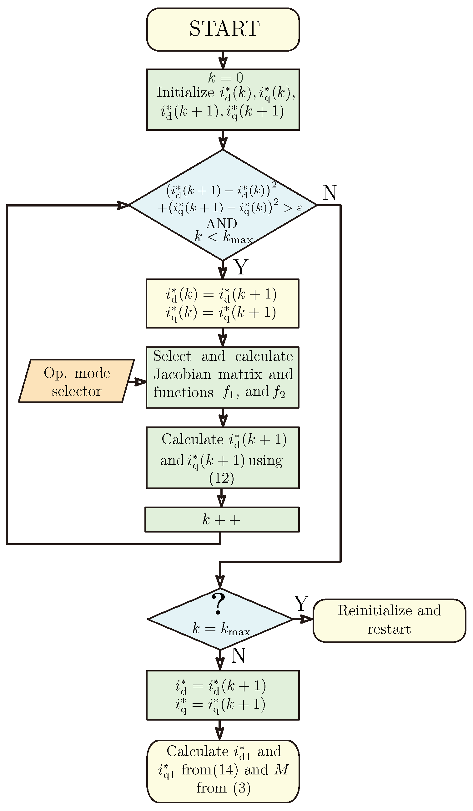
The flowchart of the Newton–Raphson (NR) reference current calculation algorithm is shown in Figure 5. As a first step, the k iteration counter should be set to zero, and the initial value of i d * ( k ) , i q * ( k ) , i d * ( k + 1 ) , and i q * ( k + 1 ) should be given. A good solution might be to set the value of i d * ( k + 1 ) and i q * ( k + 1 ) to the actual measured i d and i q values of the machine. In this case, i d * ( k ) and i d * ( k ) can be set to zero. After the initialization, the iteration process starts. Based on the actual mechanical speed and torque reference, the operation mode selector algorithm can provide the region in which the machine operates (MTPC, FW, MC, or MTPV). Depending on the actual operating mode, as well as machine parameters, the Jacobian matrix (see Appendix A) and the value of the f 1 ( i d * ( k ) , i q * ( k ) ) and f 2 ( i d * ( k ) , i q * ( k ) ) target functions (see Table 2) can be calculated. By using (12), the value of i d * ( k + 1 ) and i q * ( k + 1 ) can be updated. The iterative process is repeated either until the geometric distance of two consecutive iterations is small (see (13)) or until the maximum number of iterations k max is reached. Typically, the reference current components rapidly converge to the optimal values. If the maximum number of iterations k max is exceeded, the algorithm is not converging, and it has to be reinitialized. It should be noted that the iterative scheme outputs the optimal i d * and i q * current reference signals. The actual i d 1 * and i q 1 * reference stator current components, which are the input signals of the current controllers, can be calculated using (14).
Furthermore, from the optimal i d * and i q * current reference signals, the M electric torque can be also calculated by using (3). This is necessary in order to determine the value of M MC (maximum achievable torque belonging to MC at a given speed), M D dynamic torque (torque value at the intersection of the voltage constraint equation and the equation of the MTPC curve), or M CO cutoff torque (maximum achievable torque belonging to MTPV at a given speed) to select the proper operating mode (see Figure 4).
For example, let us assume that the machine works above the critical speed (Case 4 in Figure 4). The calculation procedure of the reference current is as follows: first the value of the cutoff torque M CO should be determined by following the iteration scheme given in Figure 5 by assuming the machine works on the MTPV curve (target functions and Jacobian matrix belonging to MTPV should be selected from Table 2). If the calculated M CO torque is smaller than M * , the machine should work on the MTPV trajectory (the left branch of Case 4 in Figure 4), and the calculated i d 1 * and i q 1 * are the optimal current reference values. However, if the calculated M CO torque is greater than M * , the machine should operate in the FW region. In this case, the iterative calculation scheme given in Figure 5 should be repeated by assuming the machine works in the FW region (target functions and Jacobian matrix belonging to FW should be selected from Table 2). The iterative process outputs the optimal i d 1 * and i q 1 * reference values.

3.7. Remark

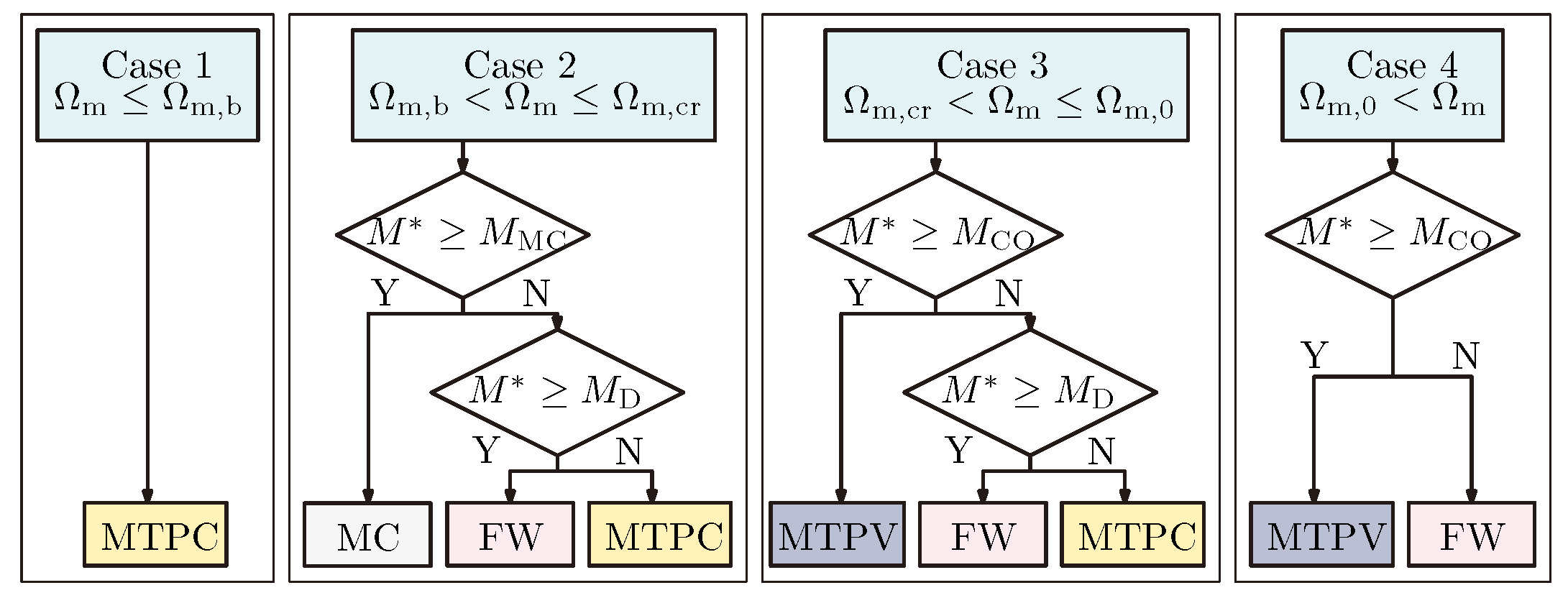
So far, the reference current calculation algorithm and the operating mode selector algorithm have been introduced by assuming that Ω m , b < Ω m , 0 < Ω m , cr . Depending on the machine parameters and the maximum allowable current and voltage values (see I max and V max ), there can be different relations among the three speed values. Figure 6 presents a flowchart of the operating mode selector, assuming Ω m , b < Ω m , cr < Ω m , 0 . In this case, when the mechanical speed is between Ω m , cr and Ω m , 0 (see Case 3 in Figure 6), at a high torque reference value, the machine works along the MTPV curve; however, at light loads, it may operate along the MTPC trajectory. It should be noted that the same equations introduced earlier in this chapter can be used to calculate the d and q axis reference currents.

4. Results

In order to verify the proposed reference current calculation strategy, which takes into account the effect of the resistance expressing iron loss, steady-state calculations and transient simulations were performed in the MATLAB R2023a environment. The nominal parameters of the investigated IPMSM can be found in Table 3. It should be noted that the machine parameters are assumed to be constant.

4.1. Operation and Convergence of the Iteration Process

The iterative convergence process of the NR-based reference current calculation algorithm for a working point given in the MTPA region ( Ω m = 150 rad/s, M * = 10 Nm) is shown in Figure 7. The initial values are selected to be i d * ( 0 ) = i q * ( 0 ) = 0 A , i d * ( 1 ) = 10 A , and i q * ( 1 ) = 10 A . The ε current setting precision is set to 5 mA2. As can be seen in Figure 7, the algorithm has a fast convergence rate, and five steps of iteration are required to reach the optimal reference points. The convergence rate of the iteration can be increased, and the required number of iteration steps can be reduced either by choosing initial values closer to the optimal reference points or by increasing the value of ε . It should be noted that the iterative scheme outputs the optimal i d * and i q * current reference signals. The actual i d 1 * and i q 1 * reference stator current components, which are the input signals of the current controllers, can be calculated using (14).

4.2. Steady-State Characteristics

Based on the parameters given in Table 3, the base speed, the boundary speed, and the critical speed can be calculated as described in Section 3. The calculated values for the nominal machine parameters are as follows: Ω m , b = 272.3 [rad/s], Ω m , 0 = 510.9 [rad/s], and Ω m , cr = 619.8 [rad/s]. To present the effect of R i on these speed values, the calculated base, boundary, and critical speeds are given in Table 4 for five different iron loss resistance values. It can be concluded that the base speed slightly increases while the boundary speed slightly decreases if the value of R i starts to decrease, that is, if iron loss starts to become significant. The effect of R i is more obvious on the value of critical speed: this speed value can increase by several percent if the resistance representing the iron loss is taken into account.
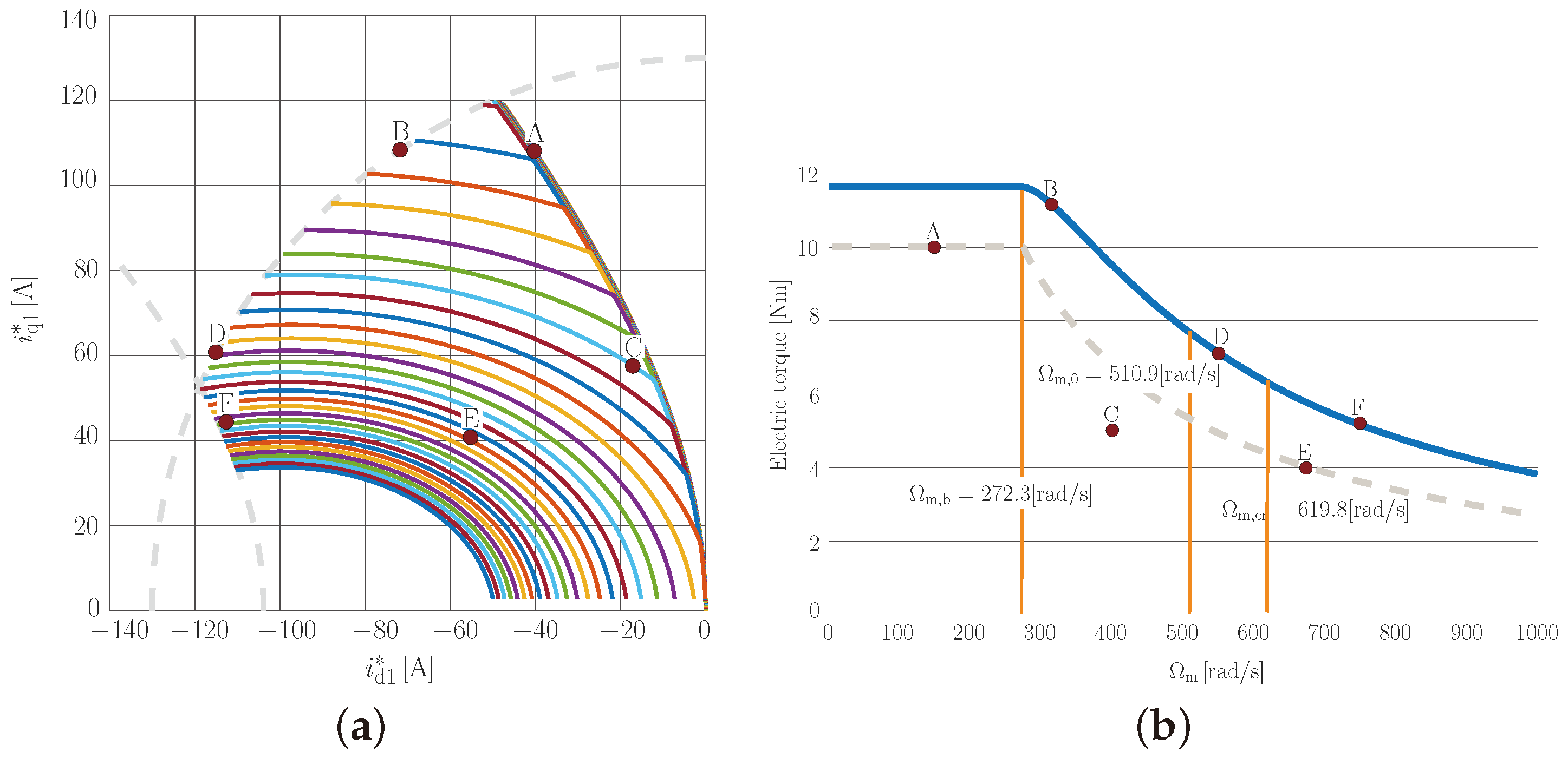
Figure 8a shows the numerically calculated trajectories of i d 1 * i q 1 * reference current pairs by sweeping the M * reference torque from zero up to its maximum value (see M max in Table 3) at different constant Ω m mechanical speed values. The Ω m values were varied between 0 and 1000 rad/s, in steps of 25 rad/s. For better visibility, the current limit circle and the MTPV curve belonging to the critical speed have been marked with a dashed line. The algorithm can be seen to provide the reference currents in the MTPC, MC, FW, and MTPV regions.
Figure 8b shows the achievable electric torque of the machine as a function of mechanical speed. The base speed, boundary speed, and critical speed are also marked in the figure. As can be seen in the figure, below the base speed, the machine can produce its maximum torque M max . Above the base speed, the achievable electric torque decreases with increasing mechanical speed. The dashed line in Figure 8b presents the allowable torque of the machine for continuous operation as a function of the mechanical speed. Below the base speed, the machine can generate nominal torque (constant torque region) while it provides nominal power above the base speed (constant power region) for continuous duty.
As previously mentioned, in the literature, the effect of iron loss resistance is typically neglected during reference current calculation. To demonstrate the effect of iron loss resistance and why it is important to consider in the calculations, Table 5 shows how i d and i q current components as well as the electric torque differ if iron loss is not taken into account during the reference calculations, even though the machine has a certain amount of R i resistance. The calculations were carried out for six different working points (denoted by A, B…F) and for five different R i values. For better comparability, these working points are examined in subsequent studies as well. The second column of Table 5 (titled R i = inf . ) shows the calculated i d 1 * and i q 1 * reference current components by neglecting the effect of iron loss. The achievable electric torque is also calculated from (3) by assuming that the current controllers work properly, and in the steady state, i d 1 = i d and i q 1 = i q track their reference signals. If the machine has a non-negligible iron loss (expressed with R i resistance as given in Figure 1), then i d 1 i d and i q 1 i q . As can be seen in Table 5, in the case of columns for different R i values, as the effect of iron loss becomes more and more significant ( R i decreases), the difference between the controlled i d 1 and i q 1 stator current components and the actual i d and i q current components, which are important in terms of torque generation, becomes considerable. These differences mean that the value of the achievable electric torque is reduced and the current controller cannot provide the reference torque. From the table, it can be concluded that, in certain operation ranges (MTPC, MC, MTPV), these differences are in the range of a few percent, even in the case of a low R i . However, in the FW operation region, a much more dominant difference can be seen. For example, the relative reduction in electric torque at working point A is 1% ( R i = 10 Ω ) and 2% ( R i = 5 Ω ), respectively. At the same time, at working points C and E, this value is 4% ( R i = 10 Ω )/7.9% ( R i = 5 Ω )/5% ( R i = 10 Ω )/10% ( R i = 5 Ω ), respectively.
Based on Table 5, it is clear that, if the machine has a non-negligible iron loss, its effect should be considered in the reference current calculation using the proposed method introduced in the current manuscript.
Table 6 shows the calculated d and q axis reference currents and the achievable electric torque for the same working points (denoted by A, B…F) and R i values using the proposed reference current calculation algorithm. These working points are also denoted in Figure 8a,b. It should be noted that the calculated values given in the second column titled R i = inf . are the same as the second column given in Table 5. Based on the values given in Table 6, it can be concluded that, for working points found in the MC or MTPV regions (such as working points B, D, and F), taking the effect of R i into account only slightly modifies the calculated d and q axis reference currents, compared to the case when the effect of iron loss is neglected. However, for working points located in either the MTPC or FW regions (such as working points A, C, and E), considering the effect of R i modifies the reference currents much more significantly. As can be seen, in these points, the machine can provide the reference torque, even when the effect of iron loss is considerable. It is a clear advantage of the proposed reference current calculation method as, in these working points, the machine cannot guarantee the reference torque if R i is not considered (compare values belonging to working points A, C, and E in Table 5 and Table 6).

4.3. Closed-Loop Operation

In order to verify the proposed reference current calculation strategy in different operation modes, a closed control loop was constructed in the MATLAB/Simulink R2023a environment similar to the block diagram in Figure 3. During the simulation study, the nominal machine parameters given in Table 3 were used. The current reference calculation algorithm was run at a sampling rate of 2 kHz, while the sampling time of the inner current loop was selected to be 20 kHz. The switching frequency of the VSI was 10 kHz. The sampling of the phase currents was synchronized to the positive and negative peaks of the carrier signal used for space vector modulation. The gains of the current controllers were calculated using the modulus optimum method, considering a one-step delay as well as K cp , d = 0.71 and K ci , q = 241.5 for the d axis current controller and K cp , q = 1 and K ci , q = 171.8 for the q axis current controller.
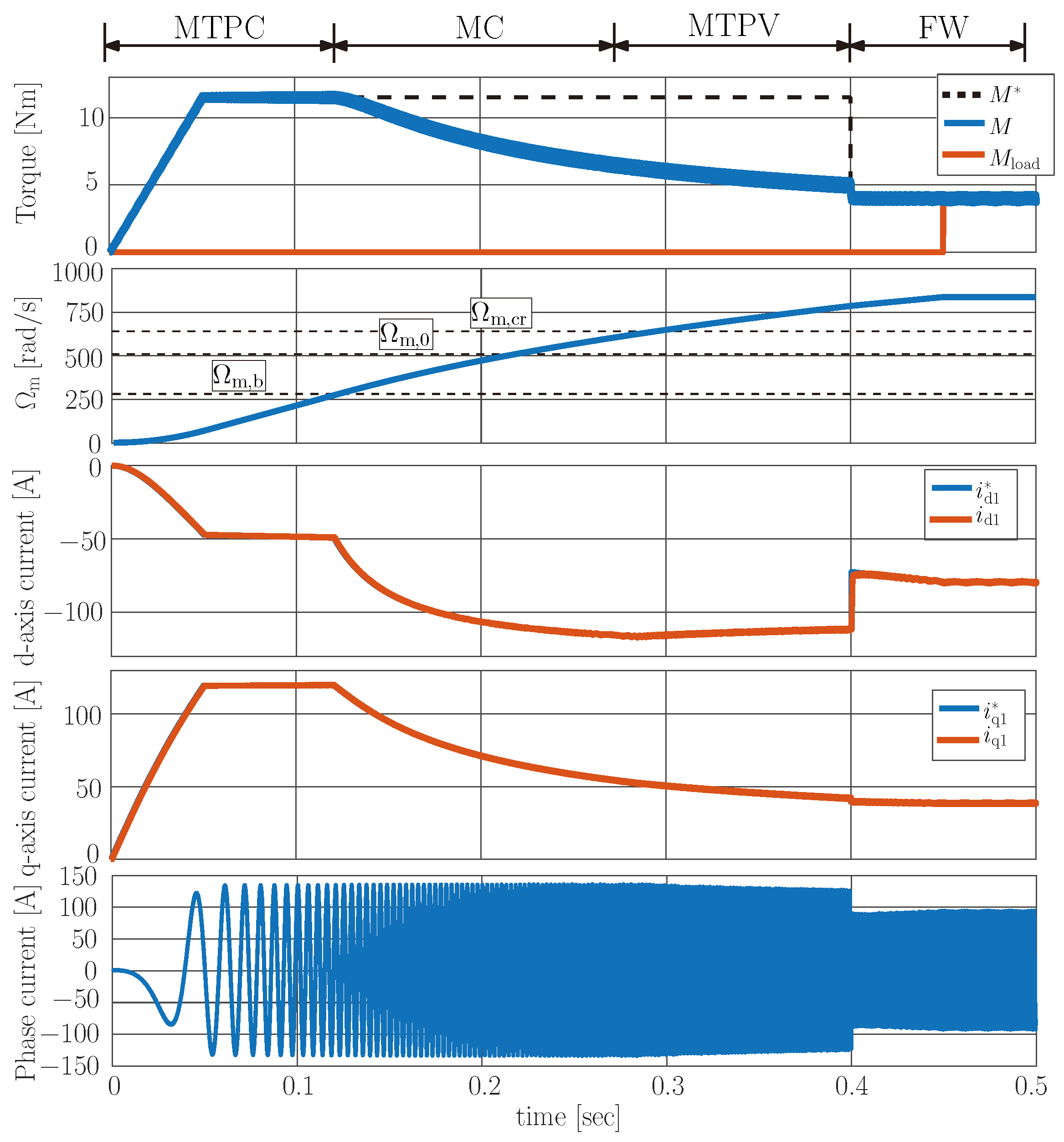
As a first step, the outer speed controller was not considered, and the actual value of the M * reference torque was generated externally. Figure 9 shows the simulated waveforms of the torque, mechanical speed, d and q axis current components, and one phase current. The M * values were changed from 0 up to M max with a ramp signal, and the loading torque was zero. The mechanical speed was increasing, and the machine worked along the MTPC curve. At t = 0.12 , the mechanical speed exceeded the base speed, and the machine entered the MC region, where both the current and the voltage reached their limit values. As can be seen, the IPMSM could not provide the reference torque anymore, so the machine accelerated further with a smaller rate. After that, the mechanical speed exceeded the Ω m , 0 boundary speed, and then, at t = 0.27 s, it exceeded the Ω m , cr critical speed as well. From this point on, the machine operated along the MTPV trajectory. At t = 0.4 s, the reference torque was reduced to 4 Nm. The machine started to operate in the FW region. At t = 0.45 s, a loading torque of 4 Nm was applied, and the mechanical speed settled down. Figure 10 shows the trajectory of d and q axis current in the i d 1 i q 1 plane. The trajectories of the MTPC, MC, MTPV, and FW regions are clearly visible.
Based on the simulated results, it can be concluded that the control requirements are fulfilled, and the current signals follow the reference signals. The IPMSM can work in the MTPC, MC, MTPV, and FW regions, and the voltage and current limits were not violated.
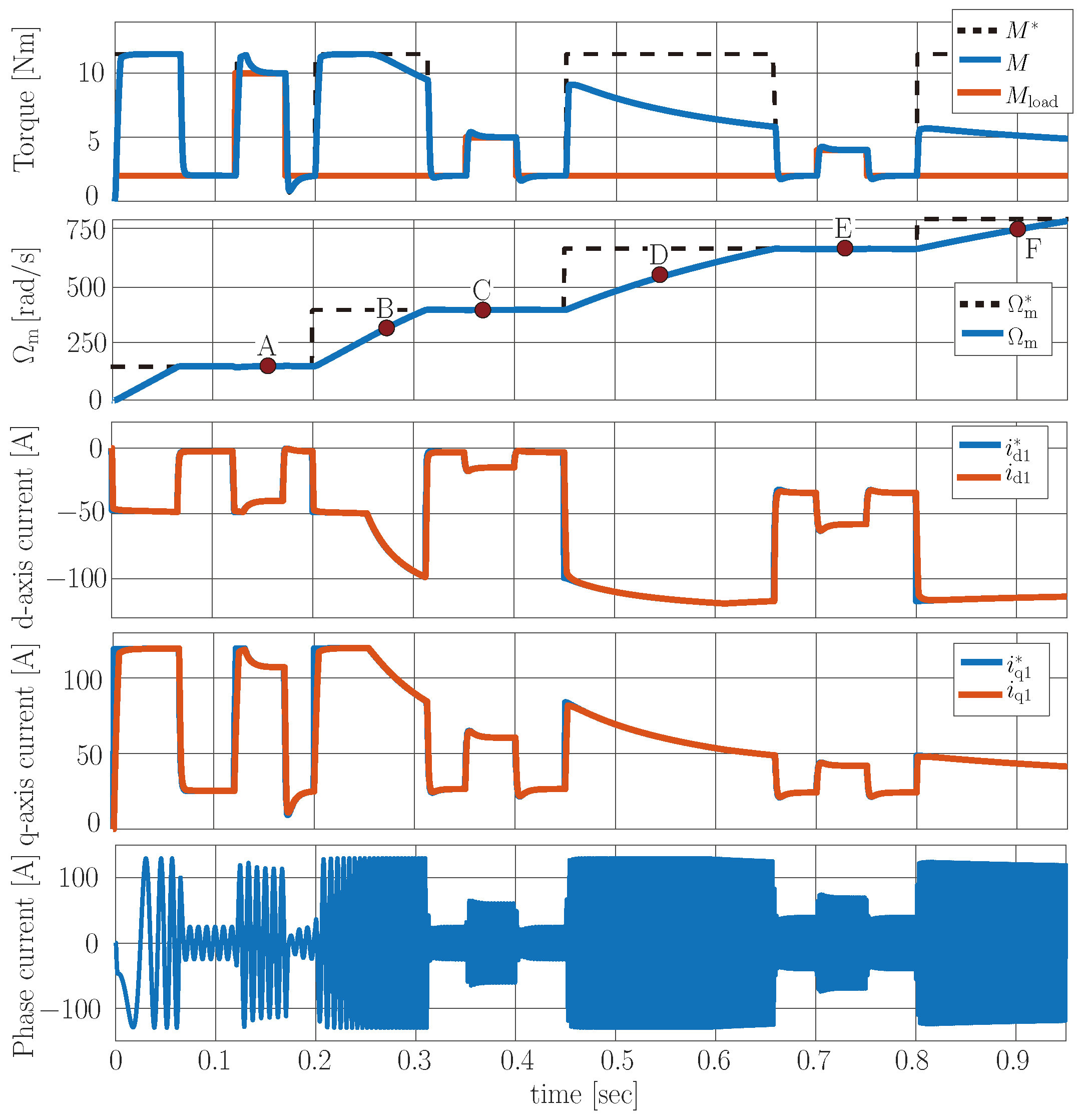
As a second step, the external speed controller was also considered in the simulation. The PI-type speed controller forms the M * reference torque based on the difference between the Ω m * reference and the actual mechanical speed Ω m . The discrete PI speed controller ran at a sampling rate of 2 kHz, similarly to the current reference generation algorithm. The gains of the controller were calculated using the symmetrical optimum method as K sp = 2.7 and K si = 125 . Figure 11 shows the simulated waveforms of the torque, mechanical speed, d and q axis current components, and one phase current. The trends for the reference mechanical speed and the load torque were determined so that, during the simulation, the drive worked at the working points (see points A, B…F in Figure 8) given in Section 4.2. As can be seen, the current reference generation algorithm works properly for sudden changes in both the reference speed and loading torque. The simulated values are consistent with the calculated quantities (see Table 6, R i = 10 Ω ).

5. Conclusions

This paper presents equations to calculate the d and q axis reference currents for the current controller of an IPMSM utilizing the Newton–Raphson-based intersect searching method. The equations and the Jacobian matrices are given for the MTPC, MC, FW, and MTPV regions. The main contribution and novelty of the paper is that the equations account for the iron loss resistance of the IPMSM, which is typically neglected in the literature. The effect of neglecting the iron loss resistance is highlighted in Table 5. It can be observed that the produced torque may differ from the reference torque by up to several percent if the iron loss is neglected. This phenomenon is mainly seen in the FW range, and it is less relevant in the MTPC, MC, and MTPV regions. If iron loss is taken into account for the reference current calculation utilizing the proposed scheme, then the machine can provide the reference torque or the maximum achievable torque even when iron loss is significant. These results are summarized in Table 6. Iron loss impacts the characteristic speeds of an IPMSM as well. With the help of the proposed scheme, the exact value of these speed values can be calculated considering the effect of iron loss. It can be concluded that the effect of R i is negligible on the value of the base speed and the boundary speed. However, iron loss can significantly increase the critical speed or, in other words, expands the MC region. These results can be observed in Table 4. These theoretical findings are validated by steady-state calculations and simulation results, which show the dynamics of the motor control scheme throughout all operation regions of an IPMSM.
Experimental results and implementation issues of the numerical searching-based reference current calculation method will be presented in another paper.

Author Contributions

Both authors contributed equally to this work. All authors have read and agreed to the published version of the manuscript.

Funding

This work was supported by the National Research, Development, and Innovation Office (NKFIH) under Grant FK 143429. Project NO. KDP-IKT-2023-900-I1-00000957/0000003 has been implemented with the support provided by the Ministry of Culture and Innovation of Hungary from the National Research, Development, and Innovation Fund, financed under the Co-operative Doctoral Program [C2247514] funding scheme.

Data Availability Statement

Data are contained within the article.

Conflicts of Interest

The authors declare no conflicts of interest.

Correction Statement

This article has been republished with a minor correction to resolve spelling and grammatical errors. This change does not affect the scientific content of the article.

Appendix A. Jacobian Matrices for Reference Current Calculation

Appendix A.1. MTPC

J MTPC = 3 2 n P Δ L i q * 3 2 n P ( Ψ PM + Δ L i d * ) 4 R s ( 1 + k d 2 ω 1 2 ) i d * + k s k d ω 1 2 k s ( 1 + k d 2 ω 1 2 ) k d k q 4 R s ( 1 + k q 2 ω 1 2 ) i q *

Appendix A.2. MC

J MC = ( 2 ( 1 + 2 k d 2 ω 1 2 ) i d * + 2 ω 1 ( k d k q ) i q * + ( 2 ( 1 + k q 2 ω 1 2 ) i q * + 2 ω 1 ( k d k q ) i d * + + 2 k P M k d ω 1 2 ) + 2 k P M ω 1 ) 2 ( R s 2 + k 1 ω 1 2 ) i d * + k 3 ω 1 i q * + k 2 ω 1 2 2 ( R s 2 + k 4 ω 1 2 ) i q * + k 3 ω 1 i d * + k 5 ω 1

Appendix A.3. FW

J FW = 3 2 n P Δ L i q * 3 2 n P ( Ψ PM + Δ L i d * ) 2 ( R s 2 + k 1 ω 1 2 ) i d * + k 3 ω 1 i q * + k 2 ω 1 2 2 ( R s 2 + k 4 ω 1 2 ) i q * + k 3 ω 1 i d * + k 5 ω 1

Appendix A.4. MTPV

J MTPV = 2 ( R s 2 + k 1 ω 1 2 ) i d * + k 3 ω 1 i q * + k 2 ω 1 2 2 ( R s 2 + k 4 ω 1 2 ) i q * + k 3 ω 1 i d * + k 5 ω 1 ( 4 Δ L R s 2 + k 1 ω 1 2 i d * + ( 4 Δ L R s 2 + k 4 ω 1 2 i q * + 2 Ψ PM ( R s 2 + k 1 ω 1 2 ) + Δ L k 2 ω 1 2 ) + ( Δ L k 5 ω 1 Ψ P M k 3 ω 1 ) )

Appendix A.5. Jacobian Matrix for Calculation of MD

J MD = 4 R s ( 1 + k d 2 ω 1 2 ) i d * + k s k d ω 1 2 k s ( 1 + k d 2 ω 1 2 ) k d k q 4 R s ( 1 + k q 2 ω 1 2 ) i q * 2 ( R s 2 + k 1 ω 1 2 ) i d * + k 3 ω 1 i q * + k 2 ω 1 2 2 ( R s 2 + k 4 ω 1 2 ) i q * + k 3 ω 1 i d * + k 5 ω 1

Appendix B. Calculation of Base Speed and Critical Speed

The value of base speed Ω m , b can be calculated by the intersection of the MTPC curve, the current limit circle, and the voltage ellipse, while the value of Ω m , cr can be calculated by the intersection of the MTPV curve, the current limit circle, and the voltage ellipse. This means that three target functions ( f 1 , f 2 , and f 3 ) must be fulfilled simultaneously. The three target functions for the calculations are summarized in Table A1.
Table A1. The f 1 , f 2 , and f 3 target functions for the calculation of base speed Ω m , b and critical speed Ω m , cr .
f 1 = 2 R s ( 1 + k q 2 ω 1 2 ) i q * 2 2 R s ( 1 + k d 2 ω 1 2 ) i d * 2 + k s k d ω 1 2 k s ( 1 + k d 2 ω 1 2 ) k d k q i d *
k s k d Ψ PM ω 1 2 Δ L = 0
Calc. of f 2 = ( 1 + k d 2 ω 1 2 ) i d * 2 + ( 1 + k q 2 ω 1 2 ) i q * 2 + 2 k P M k d ω 1 2 i d * + 2 k P M ω 1 i q *
  Ω m , b + 2 ω 1 ( k d k q ) i d * i q * + k P M 2 ω 1 2 I max 2 = 0
f 3 = ( R s 2 + k 1 ω 1 2 ) i d * 2 + k 2 ω 1 2 i d * + k 3 ω 1 i d * i q * + ( R s 2 + k 4 ω 1 2 ) i q * 2
+ k 5 ω 1 i q * + k 6 ω 1 2 V DC 2 3 = 0
f 1 = 2 Δ L R s 2 + k 1 ω 1 2 i d * 2 + 2 Δ L R s 2 + k 4 ω 1 2 i q * 2 2 Ψ PM ( R s 2 + k 1 ω 1 2 ) i d *
Δ L k 2 ω 1 2 i d * + ( Δ L k 5 ω 1 Ψ P M k 3 ω 1 ) i q * k 2 Ψ PM ω 1 2 = 0
Calc. of f 2 = ( 1 + k d 2 ω 1 2 ) i d * 2 + ( 1 + k q 2 ω 1 2 ) i q * 2 + 2 k P M k d ω 1 2 i d * + 2 k P M ω 1 i q *
  Ω m , cr + 2 ω 1 ( k d k q ) i d * i q * + k P M 2 ω 1 2 I max 2 = 0
f 3 = ( R s 2 + k 1 ω 1 2 ) i d * 2 + k 2 ω 1 2 i d * + k 3 ω 1 i d * i q * + ( R s 2 + k 4 ω 1 2 ) i q * 2
+ k 5 ω 1 i q * + k 6 ω 1 2 V DC 2 3 = 0
The three target functions contain three state variables: i d * , i q * , and ω 1 = Ω m n p . The iterative NR method presented in Section 2.5 can also be used for solving these equations. However, the Jacobian matrix will be a 3 × 3 matrix, as the partial derivations must be performed with respect to i d * , i q * , and ω 1 as follows:
J = f 1 ( i d * , i q * , ω 1 ) i d * f 1 ( i d * , i q * , ω 1 ) i q * f 1 ( i d * , i q * , ω 1 ) ω 1 f 2 ( i d * , i q * , ω 1 ) i d * f 2 ( i d * , i q * , ω 1 ) i q * f 2 ( i d * , i q * , ω 1 ) ω 1 f 3 ( i d * , i q * , ω 1 ) i d * f 3 ( i d * , i q * , ω 1 ) i q * f 3 ( i d * , i q * , ω 1 ) ω 1 .
The concept of determining the base or critical speed and their corresponding i d * and i q * current components is similar to the procedure shown in Figure 5. As a first step, the k iteration counter should be set to zero, and the initial values of i d * ( k ) , i q * ( k ) , ω 1 ( k ) i d * ( k + 1 ) , i q * ( k + 1 ) , and ω 1 ( k + 1 ) should be given. Depending on whether we would like to calculate the base or the critical speed, the actual values of the f 1 ( i d * ( k ) , i q * ( k ) , ω 1 ( k ) ) , f 2 ( i d * ( k ) , i q * ( k ) , ω 1 ( k ) ) , and f 3 ( i d * ( k ) , i q * ( k ) , ω 1 ( k ) ) target functions (see Table A1) can be calculated, and the Jacobian matrix can be also determined. The values of i d * ( k + 1 ) , i q * ( k + 1 ) , and ω 1 ( k + 1 ) can be updated as follows:
i d * ( k + 1 ) i q * ( k + 1 ) ω 1 ( k + 1 ) = i d * ( k ) i q * ( k ) ω 1 ( k ) J 1 | i d * = i d * ( k ) i q * = i q * ( k ) ω 1 = ω 1 ( k ) f 1 ( i d * ( k ) , i q * ( k ) , ω 1 ( k ) ) f 2 ( i d * ( k ) , i q * ( k ) , ω 1 ( k ) ) f 3 ( i d * ( k ) , i q * ( k ) , ω 1 ( k ) ) .
The iterative process is repeated until the geometric distance of the two iterations results is very small:
i d * ( k + 1 ) i d * ( k ) 2 + i q * ( k + 1 ) i q * ( k ) 2 + ω 1 ( k + 1 ) ω 1 ( k ) 2 < ε Ω ,
where ε Ω is the defined calculation setting precision, or the number of iterations exceeds a predefined k max number. In the latter case, the solution is not converging, and the searching algorithm has to be reinitialized.
The iterative process outputs the value of ω 1 and the corresponding i d * ( k ) and i q * ( k ) current components. The base or critical speed can be calculated as Ω m = ω 1 / n P .
It is important to mention that, due to the size of the Jacobian matrix, the base and critical speed calculations are not worth calculating in real time on an embedded device. An effective solution utilizing the proposed scheme may be to calculate offline in advance the value of the base and critical speeds and store them in the LUT as the function of the machine parameters.

References

  1. Miguel-Espinar, C.; Heredero-Peris, D.; Villafafila-Robles, R.; Montesinos-Miracle, D. Review of Flux-Weakening Algorithms to Extend the Speed Range in Electric Vehicle Applications with Permanent Magnet Synchronous Machines. IEEE Access 2023, 11, 22961–22981. [Google Scholar] [CrossRef]
  2. Zhang, S.; Yan, H.; Yang, L.; Zhao, H.; Du, X.; Zhang, J. Optimization Design of Permanent Magnet Synchronous Motor Based on Multi-Objective Artificial Hummingbird Algorithm. Actuators 2024, 13, 243. [Google Scholar] [CrossRef]
  3. Hackl, C.; Kullick, J.; Monzen, N. Generic loss minimization for nonlinear synchronous machines by analytical computation of optimal reference currents considering copper and iron losses. In Proceedings of the 2021 22nd IEEE International Conference on Industrial Technology (ICIT), Valencia, Spain, 10–12 March 2021; Volume 1, pp. 1348–1355. [Google Scholar] [CrossRef]
  4. Eldeeb, H.; Hackl, C.M.; Horlbeck, L.; Kullick, J. A unified theory for optimal feedforward torque control of anisotropic synchronous machines. Int. J. Control. 2018, 91, 2273–2302. [Google Scholar] [CrossRef]
  5. Jung, S.Y.; Hong, J.; Nam, K. Current Minimizing Torque Control of the IPMSM Using Ferrari’s Method. IEEE Trans. Power Electron. 2013, 28, 5603–5617. [Google Scholar] [CrossRef]
  6. Smídl, V.; Glac, A.; Peroutka, Z. Time-Optimal Current Control of Synchronous Motor Drives. Actuators 2023, 12, 15. [Google Scholar] [CrossRef]
  7. Wang, S.; Kang, J.; Degano, M.; Galassini, A.; Gerada, C. An Accurate Wide-Speed Range Control Method of IPMSM Considering Resistive Voltage Drop and Magnetic Saturation. IEEE Trans. Ind. Electron. 2020, 67, 2630–2641. [Google Scholar] [CrossRef]
  8. Yang, R.; Sun, T.; Feng, W.; He, S.; Zhu, S.; Chen, X. Accurate online MTPA control of IPMSM considering derivative terms. Chin. J. Electr. Eng. 2021, 7, 100–110. [Google Scholar] [CrossRef]
  9. Xia, Z.; Nalakath, S.; Tarvirdilu-Asl, R.; Sun, Y.; Wiseman, J.; Emadi, A. Online Optimal Tracking Method for Interior Permanent Magnet Machines with Improved MTPA and MTPV in Whole Speed and Torque Ranges. IEEE Trans. Power Electron. 2020, 35, 9753–9769. [Google Scholar] [CrossRef]
  10. Jeong, I.; Gu, B.G.; Kim, J.; Nam, K.; Kim, Y. Inductance Estimation of Electrically Excited Synchronous Motor via Polynomial Approximations by Least Square Method. IEEE Trans. Ind. Appl. 2015, 51, 1526–1537. [Google Scholar] [CrossRef]
  11. Yuan, T.; Chang, J.; Zhang, Y. Parameter Identification of Permanent Magnet Synchronous Motor with Dynamic Forgetting Factor Based on Hinf Filtering Algorithm. Actuators 2023, 12, 453. [Google Scholar] [CrossRef]
  12. Liu, L.; Guo, Y.; Lei, G.; Zhu, J.G. Iron loss calculation for high-speed permanent magnet machines considering rotating magnetic field and thermal effects. IEEE Trans. Appl. Supercond. 2021, 31, 5205105. [Google Scholar] [CrossRef]
  13. Nishio, Y.; Sanada, M.; Morimoto, S.; Inoue, Y. Loss Evaluation based on Experiment on Compact and High-speed IPMSM Using Strong Magnet and Low-iron-loss Material. In Proceedings of the 2020 23rd International Conference on Electrical Machines and Systems (ICEMS), Hamamatsu, Japan, 24–27 November 2020; pp. 839–844. [Google Scholar]
  14. Guo, Y.; Liu, L.; Ba, X.; Lu, H.; Lei, G.; Yin, W.; Zhu, J. Designing high-power-density electric motors for electric vehicles with advanced magnetic materials. World Electr. Veh. J. 2023, 14, 114. [Google Scholar] [CrossRef]
  15. Guo, Y.; Yu, Y.; Lu, H.; Lei, G.; Zhu, J. Enhancing Performance of Permanent Magnet Motor Drives through Equivalent Circuit Models Considering Core Loss. Energies 2024, 17, 1837. [Google Scholar] [CrossRef]
  16. Lee, B.H.; Kwon, S.O.; Sun, T.; Hong, J.P.; Lee, G.H.; Hur, J. Modeling of Core Loss Resistance for dq Equivalent Circuit Analysis of IPMSM considering Harmonic Linkage Flux. IEEE Trans. Magn. 2011, 47, 1066–1069. [Google Scholar] [CrossRef]
  17. Pairo, H.; Khanzade, M.; Shoulaie, A. Loss minimization control of interior permanent magnet synchronous motors considering self-saturation and cross-saturation. J. Power Electron. 2018, 18, 1099–1110. [Google Scholar]
  18. Xie, W.; Wang, X.; Wang, F.; Xu, W.; Kennel, R.; Gerling, D. Dynamic loss minimization of finite control set-model predictive torque control for electric drive system. IEEE Trans. Power Electron. 2015, 31, 849–860. [Google Scholar] [CrossRef]
  19. Ding, S.; Fan, Z.; Hang, J.; Li, W.; Wang, Z. Simplified Loss Minimization Control for Interior Permanent Magnet Synchronous Machine Based on Virtual Current Signal. IEEE Trans. Ind. Electron. 2024, 71, 8601–8610. [Google Scholar] [CrossRef]
  20. Hou, L.; Guo, Y.; Ba, X.; Lei, G.; Zhu, J. Efficiency Improvement of Permanent Magnet Synchronous Motors Using Model Predictive Control Considering Core Loss. Energies 2024, 17, 773. [Google Scholar] [CrossRef]
  21. Balamurali, A.; Kundu, A.; Li, Z.; Kar, N.C. Improved Harmonic Iron Loss and Stator Current Vector Determination for Maximum Efficiency Control of PMSM in EV Applications. IEEE Trans. Ind. Appl. 2021, 57, 363–373. [Google Scholar] [CrossRef]
  22. Járdán, R.K.; Stumpf, P.; Varga, Z.; Endisch, C.; Sipos, P.; Simon, M. Laboratory system for measurement of iron losses in high speed drives. Int. J. Hydrogen Energy 2016, 41, 12650–12658. [Google Scholar] [CrossRef]
  23. Boubaker, N.; Matt, D.; Enrici, P.; Nierlich, F.; Durand, G. Measurements of Iron Loss in PMSM Stator Cores Based on CoFe and SiFe Lamination Sheets and Stemmed From Different Manufacturing Processes. IEEE Trans. Magn. 2019, 55, 8100309. [Google Scholar] [CrossRef]
  24. Xu, K.; Guo, Y.; Lei, G.; Zhu, J. Estimation of Iron Loss in Permanent Magnet Synchronous Motors Based on Particle Swarm Optimization and a Recurrent Neural Network. Magnetism 2023, 3, 327–342. [Google Scholar] [CrossRef]
  25. Liu, G.; Liu, M.; Zhang, Y.; Wang, H.; Gerada, C. High-Speed Permanent Magnet Synchronous Motor Iron Loss Calculation Method Considering Multiphysics Factors. IEEE Trans. Ind. Electron. 2020, 67, 5360–5368. [Google Scholar] [CrossRef]
Figure 1. A d q axis equivalent circuit model of an IPMSM incorporating iron loss resistance; (a) d axis; (b) q axis.
Actuators 13 00321 g001
Figure 2. Operation regions of IPMSM on the i d 1 i q 1 plane.
Actuators 13 00321 g002
Figure 3. Block diagram of closed-loop control of the IPMSM.
Actuators 13 00321 g003
Figure 4. Flowchart of the operating mode selector assuming Ω m , b < Ω m , 0 < Ω m , cr .
Actuators 13 00321 g004
Figure 5. Flowchart of the NR-based reference current calculation algorithm.
Actuators 13 00321 g005
Figure 6. Flowchart of the operating mode selector, assuming Ω m , b < Ω m , cr < Ω m , 0 .
Actuators 13 00321 g006
Figure 7. Iterative convergence process of the NR-based reference current calculation algorithm for a working point given in the MTPA region ( Ω m = 150 rad/s, M * = 10 Nm).
Actuators 13 00321 g007
Figure 8. Steady-state characteristic curves. (a) Numerically calculated i d 1 * i q 1 * trajectories at constant mechanical speeds; (b) maximum achievable electric torque (blue line) and allowable torque for continuous operation (dashed line) versus mechanical speed characteristics.
Actuators 13 00321 g008
Figure 9. Simulation results. Dynamic performance of the closed-loop current control using the proposed current reference generation algorithm with externally generated reference torque.
Actuators 13 00321 g009
Figure 10. Simulation results. Trajectory of the stator current in the dq plane using the proposed current reference generation algorithm with externally generated reference torque.
Actuators 13 00321 g010
Figure 11. Simulation results. Dynamic performance of the closed-loop operation using the proposed current reference generation algorithm and utilizing an external speed controller.
Actuators 13 00321 g011
Table 1. Characteristic speeds of an IPMSM.
NameSymbolDescription
Base speed Ω m , b The speed at which the motor can still produce maximum torque.
Boundary speed Ω m , 0 Speed at which the voltage ellipse intersects the origo of the i d 1 i q 1 map.
Critical speed Ω m , cr Speed at which the voltage ellipse intersects the MC and MTPV curves.
Table 2. The f 1 and f 2 target functions for different operation regions and for the calculation of M D .
MTPC f 1 = M * 3 2 n P i q * ( Ψ PM + Δ L i d * ) = 0
f 2 = 2 R s ( 1 + k q 2 ω 1 2 ) i q * 2 2 R s ( 1 + k d 2 ω 1 2 ) i d * 2 + k s k d ω 1 2 k s ( 1 + k d 2 ω 1 2 ) k d k q i d *
k s k d Ψ PM ω 1 2 Δ L = 0
MC f 1 = ( 1 + k d 2 ω 1 2 ) i d * 2 + ( 1 + k q 2 ω 1 2 ) i q * 2 + 2 k P M k d ω 1 2 i d * + 2 k P M ω 1 i q *
+ 2 ω 1 ( k d k q ) i d * i q * + k P M 2 ω 1 2 I max 2 = 0
f 2 = ( R s 2 + k 1 ω 1 2 ) i d * 2 + k 2 ω 1 2 i d * + k 3 ω 1 i d * i q * + ( R s 2 + k 4 ω 1 2 ) i q * 2
+ k 5 ω 1 i q * + k 6 ω 1 2 V DC 2 3 = 0
FW f 1 = M * 3 2 n P i q * ( Ψ PM + Δ L i d * ) = 0  
f 2 = ( R s 2 + k 1 ω 1 2 ) i d * 2 + k 2 ω 1 2 i d * + k 3 ω 1 i d * i q * + ( R s 2 + k 4 ω 1 2 ) i q * 2
+ k 5 ω 1 i q * + k 6 ω 1 2 V DC 2 3 = 0
MTPV f 1 = ( R s 2 + k 1 ω 1 2 ) i d * 2 + k 2 ω 1 2 i d * + k 3 ω 1 i d * i q * + ( R s 2 + k 4 ω 1 2 ) i q * 2
+ k 5 ω 1 i q * + k 6 ω 1 2 V DC 2 3 = 0
f 2 = 2 Δ L R s 2 + k 1 ω 1 2 i d * 2 + 2 Δ L R s 2 + k 4 ω 1 2 i q * 2 2 Ψ PM ( R s 2 + k 1 ω 1 2 ) i d *
Δ L k 2 ω 1 2 i d * + ( Δ L k 5 ω 1 Ψ P M k 3 ω 1 ) i q * k 2 Ψ PM ω 1 2 = 0
Calc. of M D f 1 = 2 R s ( 1 + k q 2 ω 1 2 ) i q * 2 2 R s ( 1 + k d 2 ω 1 2 ) i d * 2 + k s k d ω 1 2 k s ( 1 + k d 2 ω 1 2 ) k d k q i d *
k s k d Ψ PM ω 1 2 Δ L = 0
f 2 = ( R s 2 + k 1 ω 1 2 ) i d * 2 + k 2 ω 1 2 i d * + k 3 ω 1 i d * i q * + ( R s 2 + k 4 ω 1 2 ) i q * 2
+ k 5 ω 1 i q * + k 6 ω 1 2 V DC 2 3 = 0
Table 3. Nominal IPMSM parameters.
ParameterSymbolValue and Unit
Stator resistance R s 0.0256   [ Ω ]
Flux of PM Ψ PM 0.01082   [Vs]
d axis inductance L d 0.106  [mH]
q axis inductance L q 0.149   [mH]
Number of pole pairs n P 5
DC link voltage V DC 48   [V]
Maximum stator current I max 130   [A]
Nominal stator current I n 115   [A]
Resistance expressing iron loss R i 10   [ Ω ]
Maximum electric torque M max 11.63   [Nm]
Nominal electric torque M n 10   [Nm]
Nominal mechanical speed Ω n 272.3   [rad/s]
Nominal mechanical power P m , n 2.7   [kW]
Nominal input electric power P 1 , n 3.3   [kW]
Total drive inertiaJ0.004   [ kg · m 2 ]
Table 4. Effect of R i on base, boundary, and critical speed values.
R i = i n f . R i = 40 [Ω] R i = 20 [Ω] R i = 10 [Ω] R i = 5 [Ω]
Base speed Ω m , b [rad/s]270.3270.8271.1272.3274.3
Boundary speed Ω m , 0 [rad/s]512.2511.9511.6510.9509.6
Critical speed Ω m , cr [rad/s]594.8600.7606.8619.8648.8
Table 5. Calculated i d and i q current components and achievable torque for different working points if R i is neglected during reference current calculation.
R i = i n f . R i = 40 [Ω] R i = 20 [Ω] R i = 10 [Ω] R i = 5 [Ω]
A Ω m = 150 rad/s i d 1 * = 39.1 [A] i d = 38.8 [A] i d = 38.5 [A] i d = 37.9 [A] i d = 36.7 [A]
M * = 10 Nm i q 1 * = 106.6 [A] i q = 106.4 [A] i q = 106.3 [A] i q = 106.1 [A] i q = 105.6 [A]
MTPC M = 10 [Nm] M = 9.97 [Nm] M = 9.95 [Nm] M = 9.9 [Nm] M = 9.8 [Nm]
B Ω m = 310 rad/s i d 1 * = 73.3 [A] i d = 72.7 [A] i d = 72.1 [A] i d = 70.8 [A] i d = 68.4 [A]
M * = M max i q 1 * = 107.4 [A] i q = 107.3 [A] i q = 107.1 [A] i q = 106.9 [A] i q = 106.3 [A]
MC M = 11.25 [Nm] M = 11.22 [Nm] M = 11.18 [Nm] M = 11.11 [Nm] M = 10.97 [Nm]
C Ω m = 400 rad/s i d 1 * = 12.9 [A] i d = 12.46 [A] i d = 12.04 [A] i d = 11.2 [A] i d = 9.64 [A]
M * = 5 [Nm] i q 1 * = 58.6 [A] i q = 58.1 [A] i q = 57.6 [A] i q = 56.6 [A] i q = 54.7 [A]
FW M = 5 [Nm] M = 4.95 [Nm] M = 4.9 [Nm] M = 4.8 [Nm] M = 4.6 [Nm]
D Ω m = 550 rad/s i d 1 * = 115.2 [A] i d = 114.6 [A] i d = 114 [A] i d = 112.7 [A] i d = 110.2 [A]
M * = M max i q 1 * = 60.2 [A] i q = 60.3 [A] i q = 60.4 [A] i q = 60.5 [A] i q = 60.7 [A]
MC M = 7.13 [Nm] M = 7.12 [Nm] M = 7.11 [Nm] M = 7.11 [Nm] M = 7.08 [Nm]
E Ω m = 670 rad/s i d 1 * = 55.9 [A] i d = 55.4 [A] i d = 54.9 [A] i d = 53.97 [A] i d = 52.23 [A]
M * = 4 [Nm] i q 1 * = 40.3 [A] i q = 39.88 [A] i q = 39.46 [A] i q = 38.6 [A] i q = 36.8 [A]
FW M = 4 [Nm] M = 3.94 [Nm] M = 3.9 [Nm] M = 3.8 [Nm] M = 3.6 [Nm]
F Ω m = 750 rad/s i d 1 * = 112.2 [A] i d = 111.6 [A] i d = 111 [A] i d = 109.7 [A] i d = 107.2 [A]
M * = M max [Nm] i q 1 * = 44.2 [A] i q = 44.3 [A] i q = 44.38 [A] i q = 44.5 [A] i q = 44.6 [A]
MTPV M = 5.18 [Nm] M = 5.18 [Nm] M = 5.19 [Nm] M = 5.19 [Nm] M = 5.16 [Nm]
Table 6. Calculated d and q axis reference currents for different working points using the proposed scheme.
R i = i n f . R i = 40 [Ω] R i = 20 [Ω] R i = 10 [Ω] R i = 5 [Ω]
A Ω m = 150 rad/s i d 1 * = 39.1 [A] i d 1 * = 39.4 [A] i d 1 * = 39.7 [A] i d 1 * = 40.3 [A] i d 1 * = 41.53 [A]
M * = 10 Nm i q 1 * = 106.6 [A] i q 1 * = 106.8 [A] i q 1 * = 106.9 [A] i q 1 * = 107.2 [A] i q 1 * = 107.6 [A]
MTPC M = 10 [Nm] M = 10 [Nm] M = 10 [Nm] M = 10 [Nm] M = 10 [Nm]
B Ω m = 310 rad/s i d 1 * = 73.3 [A] i d 1 * = 73.2 [A] i d 1 * = 73.2 [A] i d 1 * = 73.2 [A] i d 1 * = 73.1 [A]
M * = M max i q 1 * = 107.4 [A] i q 1 * = 107.4 [A] i q 1 * = 107.4 [A] i q 1 * = 107.4 [A] i q 1 * = 107.5 [A]
MC M = 11.25 [Nm] M = 11.22 [Nm] M = 11.18 [Nm] M = 11.11 [Nm] M = 11 [Nm]
C Ω m = 400 rad/s i d 1 * = 12.9 [A] i d 1 * = 13.4 [A] i d 1 * = 13.9 [A] i d 1 * = 14.8 [A] i d 1 * = 16.6 [A]
M * = 5 [Nm] i q 1 * = 58.6 [A] i q 1 * = 59.1 [A] i q 1 * = 59.5 [A] i q 1 * = 60.5 [A] i q 1 * = 62.3 [A]
FW M = 5 [Nm] M = 5 [Nm] M = 5 [Nm] M = 5 [Nm] M = 5 [Nm]
D Ω m = 550 rad/s i d 1 * = 115.2 [A] i d 1 * = 115.3 [A] i d 1 * = 115.3 [A] i d 1 * = 115.3 [A] i d 1 * = 115.3 [A]
M * = M max i q 1 * = 60.2 [A] i q 1 * = 60.1 [A] i q 1 * = 60 [A] i q 1 * = 60 [A] i q 1 * = 59.9 [A]
MC M = 7.13 [Nm] M = 7.11 [Nm] M = 7.1 [Nm] M = 7.1 [Nm] M = 7.1 [Nm]
E Ω m = 670 rad/s i d 1 * = 55.9 [A] i d 1 * = 56.5 [A] i d 1 * = 57.1 [A] i d 1 * = 58.2 [A] i d 1 * = 60.5 [A]
M * = 4 [Nm] i q 1 * = 40.3 [A] i q 1 * = 40.7 [A] i q 1 * = 41.1 [A] i q 1 * = 41.9 [A] i q 1 * = 43.5 [A]
FW M = 4 [Nm] M = 4 [Nm] M = 4 [Nm] M = 4 [Nm] M = 4 [Nm]
F Ω m = 750 rad/s i d 1 * = 112.2 [A] i d 1 * = 112.8 [A] i d 1 * = 113.4 [A] i d 1 * = 114.6 [A] i d 1 * = 117 [A]
M * = M max [Nm] i q 1 * = 44.2 [A] i q 1 * = 44 [A] i q 1 * = 43.9 [A] i q 1 * = 43.7 [A] i q 1 * = 43.2 [A]
MTPV M = 5.18 [Nm] M = 5.18 [Nm] M = 5.17 [Nm] M = 5.17 [Nm] M = 5.16 [Nm]
Disclaimer/Publisher’s Note: The statements, opinions and data contained in all publications are solely those of the individual author(s) and contributor(s) and not of MDPI and/or the editor(s). MDPI and/or the editor(s) disclaim responsibility for any injury to people or property resulting from any ideas, methods, instructions or products referred to in the content.