Article

Research on Camera Rotation Strategies for Active Visual Perception in the Self-Driving Vehicles

by
Xiangcun Kong
1,
Shuyue Shi
1,
Bingchen Yan
2,
Shuzhe Si
3,
Juan Ni
1,
Dong Guo
1,
Pengwei Wang
1,
Lei Wang
3 and
Yi Xu
1,4,*
1
School of Transportation and Vehicle Engineering, Shandong University of Technology, Zibo 255000, China
2
Zibo Environmental Pollution Control and Prevention Center, Zibo 255000, China
3
Cestera Motor Co., Ltd., Zibo 255000, China
4
QINGTE Group Co., Ltd., Qingdao 266106, China
*
Author to whom correspondence should be addressed.
Actuators 2024, 13(8), 317; https://doi.org/10.3390/act13080317
Submission received: 22 July 2024 / Revised: 18 August 2024 / Accepted: 19 August 2024 / Published: 20 August 2024

Abstract

:
Aiming at the problem of blind field of view caused by the change in the vehicle’s yaw angle when the self-driving vehicle is turning or changing lanes, this paper proposes a camera rotation strategy based on monocular active environment sensing, which realizes the detection of the blind field of view when the vehicle’s yaw angle changes in the self-driving vehicle. Based on the two-degrees-of-freedom dynamic model, the camera rotation angle control is achieved by controlling the front-wheel angle of the vehicle. A camera control module is designed using Simulink to control the camera in real-time, allowing it to rotate based on different driving scenes. The effect of obstacle detection by traditional vision sensors and active vision sensors is tested under different vehicle driving scenes. The results demonstrate that the obstacle detection effect of the camera rotation strategy based on monocular active environment perception, as designed in this paper, is better than the traditional monocular vision.

1. Introduction

In recent years, along with the cross-fusion application of high technology in various fields, research on intelligent devices has developed rapidly [1]. In the field of intelligent transport, driverless technology has emerged along with the progress in science and technology. The self-driving vehicles have been equipped with autonomous perception, planning, control, navigation, decision-making, and other capabilities that are not available in conventional human-operated vehicles. Its appearance brings great convenience to people in self-driving travel [2]. Self-driving vehicles perceive information about their surroundings through an environmental sensing system, which is a prerequisite for safe vehicle operation [3].
For the active camera repositioning problem, M Pan et al. focused on in situ perception of the same scene by actively adjusting the camera motion and repositioning the camera to the target pose [4]. N Xu et al. proposed an active target detection framework aimed at building a bridge between the imaging configuration and the target detection task, in which the camera was actively controlled to maximize the detection performance [5]. Kyrkou et al. proposed a deep convolutional camera-controller neural network to provide an effective solution to the active vision problem directly from visual information to camera motion. Experimental results showed that the proposed solution was robust to different conditions and was able to achieve better monitoring performance than traditional methods in terms of the number of monitored targets and effective monitoring time [6]. S Casao et al. constructed a new framework that exploited the synergy between the tracking and control modules to obtain a system that was closer to practical applications and capable of advanced scene understanding. Experiments demonstrated the advantages of collaborative mobile cameras over static or individual camera setups [7]. Zhang Q et al. proposed a fast and robust ACR scheme, rACR, for the active camera relocation (ACR) problem, which worked well under highly variable schematics [8]. For the problem of actively exploring unknown indoor environments using RGB-D cameras, Dai X Y et al. proposed a novel active vSLAM framework with camera-view planning based on generative adversarial imitation learning (GAIL) for actively reorienting the camera during robot motion in order to avoid tracking failures while ensuring adequate exploration [9]. To address the partial detection of obstacles, Guan R et al. designed a rotating device that allowed the camera to actively extend its viewing range and resolve conflicts with leader detection [10]. Oh X et al. proposed a positioning system that required no infrastructure and no field calibration, which used a single active pan–tilt–zoom camera to detect, track, and position circular LED markers [11]. Kakaletsis E et al. proposed an active method that utilized facial views generated from realistic facial image rendering. The method utilized the ability of robots to interact with their environment through active vision to improve their performance in various perceptual tasks [12]. Hu J et al. proposed a novel active robot perception framework that generated sensor views online based on collected data to improve the estimated pose. Experimental results showed that the method improved the pose estimation accuracy and verified the overall effectiveness of the active perception strategy [13].
Wei X designed a multitask deep convolutional neural network, which detected targets appearing in the field of view of the self-driving vehicle in real time based on monocular images, and obtained the distance ahead between the target vehicle or person and the appearance of the vehicle’s camera [14]. Martínez-Díaz S introduced a new method for calculating the distance of a single image of a desired object with known dimensions captured using a monocular calibrated vision system. The system was tested and compared with a calibrated stereovision system. The results showed that both systems performed similarly, but the monocular system completed the task in a shorter time [15]. Liu Y modified the pixelwise a posteriori 3D (PWP3D) framework and proposed a fast PWP3D algorithm for high-speed target tracking and attitude estimation. Unlike the original PWP3D method, this method improved the tracking speed and the method improved the tracking accuracy for environmental changes compared to the original PWP3D algorithm [16]. Kim M proposed an obstacle avoidance strategy based on deep reinforcement learning for a small monocular camera mounted on a compact multirotor UAV. The proposed method was verified to have good performance and robustness by simulation and practical experiments using a Parrot Bebop2 UAV in various complex indoor environments [17]. Kim I S proposed a height estimation method for predicting the height of an object directly from a two-dimensional image. The method utilized an encoder–decoder network for pixel-dense prediction based on height consistency. Experimental results showed that the height map of an object can be estimated regardless of the camera’s position [18]. Dang T V proposed a real-time obstacle avoidance strategy for monocular camera mobile robots. The method used binary semantic segmentation FCN-VGG-16 to extract features from images captured by the monocular camera and to estimate the location and distance of obstacles in the robot’s environment. Experimental results showed that the method could successfully detect and avoid static and dynamic obstacles in real time with high accuracy, high efficiency, and smooth turning with low angular variations [19]. In order to achieve autonomous flight of a UAV that can immediately process and respond to information from its surroundings, Chuang H M proposed a direct visual servo system for UAVs using an onboard high-speed monocular camera. Experimental results showed that the UAV was able to recognize targets at an update rate of about 350 Hz and successfully achieved the target tracking task [20]. Wenning M, based on the assumption that recent advances in convolutional neural network algorithms allow the replacement of ranging laser scanners with a common single camera, proposed a realistic 3D simulation of a factory environment for testing vision-based obstacle detection algorithms prior to field testing of safety-critical systems [21]. Sakagawa Y proposed a method for vehicle detection from the images of an in-vehicle monocular camera taken while driving at night. In this method, vehicle detection was performed by weighting the results of a random forest based on features of vehicle highlights and features of highlights unrelated to the vehicle. The effectiveness of the method was confirmed by night images [22]. Venkateswaran N presented a novel distance prediction system based on monocular vision. The system is composed of a pre-trained YOLO (you only look once) model, Hungarian algorithm, Kalman filter, and inverse perspective mapping (IPM). A quantitative evaluation of video clips recorded in a traffic environment showed that the proposed FCW system was able to efficiently estimate the intervehicle distances and their relative velocities, and thus was able to predict collisions with a high degree of accuracy [23].
However, when a vehicle is changing lanes or turning, the driving behavior requires a change in the visual threshold while the vehicle has a change in the yaw angle. Therefore, this paper combines the vehicle system dynamic to compensate for the change in yaw angle and uses an active camera to realize the change in the visual threshold, so as to solve the problem of the visual field blindness that exists in the vehicle when changing lanes or turning. Therefore, a camera rotation strategy method for active visual environment perception is proposed in this paper, which takes a monocular camera as the active visual sensor. When the self-driving vehicle is changing lanes or turning, the active visual sensor will rotate the corresponding angle according to the vehicle’s own attitude, thereby detecting in advance the road conditions that the vehicle will encounter, so as to avoid traffic accidents due to the visual blind area of the self-driving vehicle.
The remainder of this paper is as follows: Section 2 calculates the body yaw angle of the self-driving vehicle when changing lanes or turning according to the two-degrees-of-freedom vehicle dynamic model, and builds the camera control model through Simulink, and controls the camera to rotate in advance through the control system, so that the self-driving vehicle can achieve the accurate detection of the road conditions when changing lanes or turning. Section 3 introduces the camera rotation strategies for the self-driving vehicle in different driving scenes, and ensures the effective detection of the external environment of the self-driving vehicle in different driving scenes through different rotation strategies. Section 4 designs obstacle detection experiments for the theoretical method proposed in this paper, and verifies the superiority of this method through real vehicle experiments. Section 5 concludes the paper. The system workflow diagram is shown in Figure 1.

2. Camera Rotation Angle Acquisition Model

When a vehicle changes lanes or turns, due to the change in the vehicle’s yaw angle, there may be a momentary blind spot to the road it is about to enter. This can lead to the vehicle failing to detect road information in front of the lane. If there is an obstacle in front of the lane, the vehicle may not detect it in time, leading to a lack of reaction time and potentially causing traffic accidents. Therefore, for this situation, a method of detecting road information by camera rotation in advance is proposed in this paper, and the angle of camera rotation in different situations is the most important part of this method. Therefore, this paper is based on the two-degrees-of-freedom vehicle dynamic model to obtain the vehicle yaw angle, so that the vehicle can determine the camera rotation angle by its own yaw angle under different driving situations.
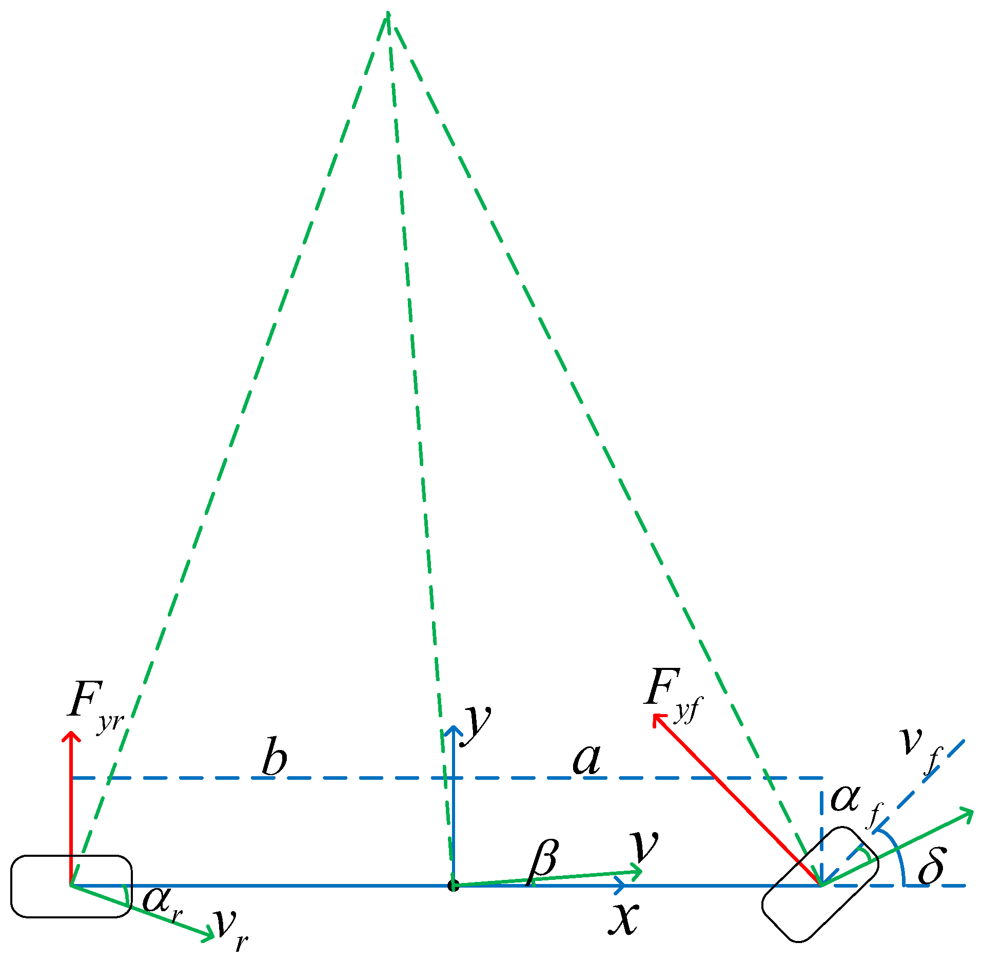
A very important qualification inside the vehicle kinematics model is to consider that the vehicle is traveling at low speeds, in which case we can consider the tire to be a rigid tire, with no sideways bias characteristics; i.e., the tire-turning angle of the vehicle tire along the body coordinate system and the direction of the tire’s velocity are the same. But when the wheels are traveling at high speed, the tire cannot be approximated as a rigid tire. When the tire is subjected to a side deflection force, the result is that the direction of the wheel’s velocity and the tire’s turning angle do not coincide, and the difference is the side deflection angle (the angle between the velocity and the wheel’s x-axis). At this point, the kinematic model is no longer applicable and a dynamic model needs to be used. When the vehicle is changing lanes or turning, the analysis described herein only considers the motion of the y-axis and rotation around the z-axis in the transverse direction and ignores the motion and force of the x-axis in the longitudinal direction. Therefore a two-degrees-of-freedom vehicle dynamic model is established, as shown in Figure 2.
Establishing a right-angle coordinate system at the center of mass, the distance from the center of mass of the vehicle to the front wheels is a , the distance to the rear wheels is b , and the angle of rotation of the front wheels is δ . The lateral forces acting on the front and rear wheels are F y f and F y r , respectively. The front, center of mass, and rear wheel speed are v f , v , and v r , respectively. The front wheel, center of mass, and the sideslip angle of the rear wheels are α f , β , and α r , respectively.
From Figure 2, it is clear that both α r and α f are negative.
From F y = m a y , it follows that the force analysis equation is:
m a y = F y f cos δ + F y r
where a y represents the lateral acceleration of the vehicle.
From M = I φ ¨ , it follows that the moment equation is:
F y f cos δ a F y r b = I φ ¨
Assuming that δ is smaller, then cos δ 1 . Bringing in the simplification gives:
m a y = F y f + F y r = C a f α f + C a r α r
I φ ¨ = F y f a F y r b = a C a f α f b C a r α r
where C is the lateral stiffness, I is the distance vector from the axis of rotation to the point of impact, and φ ¨ is the vector force.
Under different driving environments, when δ is small, then cos δ can be approximated as 1. In this paper, we analyze and verify by Equation (5):
tan δ = L R
where L denotes the wheelbase of the vehicle, which is about 3 m, and R is the turning radius, which in the usual case is about 8 12   m . When R is 8, tan δ achieves its maximum value, at which time cos δ is about 0.93, which can be approximated as 1.
Take right turning as an example: when the vehicle is in a right-turning right-angle turn, at this time the vehicle’s turning wheel angle is the largest, and the turning radius is the smallest. According to the relevant national standards for the design of roads, the turning radius in this case will not be less than 8 10   m , which also meets the condition that cos δ is approximately 1.
In the case of a left-lane change, for example, when a driver spots an obstacle ahead of his or her home lane to overtake and change lanes, the radius of the turn at this point is approximately 20 30   m , again satisfying the condition that cos δ is approximately 1.
Since the ultimate goal of this section is to achieve control of the vehicle’s yaw angle through the vehicle’s front-wheel angle δ , it is necessary to know the relationship between a y and y , as well as the exact expression for a f , a r .
v y = y ˙
a y = y ¨ + v x φ ˙
A bicycle model is built as shown in Figure 3a. Connecting v r and v , the resulting vector is perpendicular to the axis of the vehicle, which is noted as φ ˙ b . Figure 3b shows the decomposition of the velocity at the center of mass of the bicycle model, and Figure 3c shows the decomposition of the velocity at the front wheel of the bicycle model.
From Figure 3b, it follows that
tan α r = φ ˙ b v y v x α r
Since α r is negative, it follows that
α r = v y φ ˙ b v x
From Figure 3c, it follows that
tan θ = φ ˙ a + v y v x
α f = θ δ = φ ˙ a + v y v x δ
The equation for the sideslip angle is substituted into the Newton’s second power formula for the vehicle dynamic.
From m a y = C α f α f + C α r α r , it follows that
m v y + v x φ ˙ = C α f φ ˙ a + v y v x δ + C α r v y φ ˙ b v x
From I φ ¨ = a C α f α f b C α r α r , it follows that
I φ ¨ = a C α f φ ˙ a + v y v x δ b C α r v y φ ˙ b v x
Replacing v y with y ˙ gives:
y ¨ φ ¨ = C α f + C α r m v x a C α f b C α r m v x v x a C α f b C α r I v x a 2 C α f + b 2 C α r I v x y ˙ φ ˙ + C α f m a C α r I δ
Assuming X = y ˙ φ ˙ , u = δ , the governing equation is:
X ˙ = A X + B u
By controlling δ , the control of φ is achieved and therefore the value of φ is obtained.
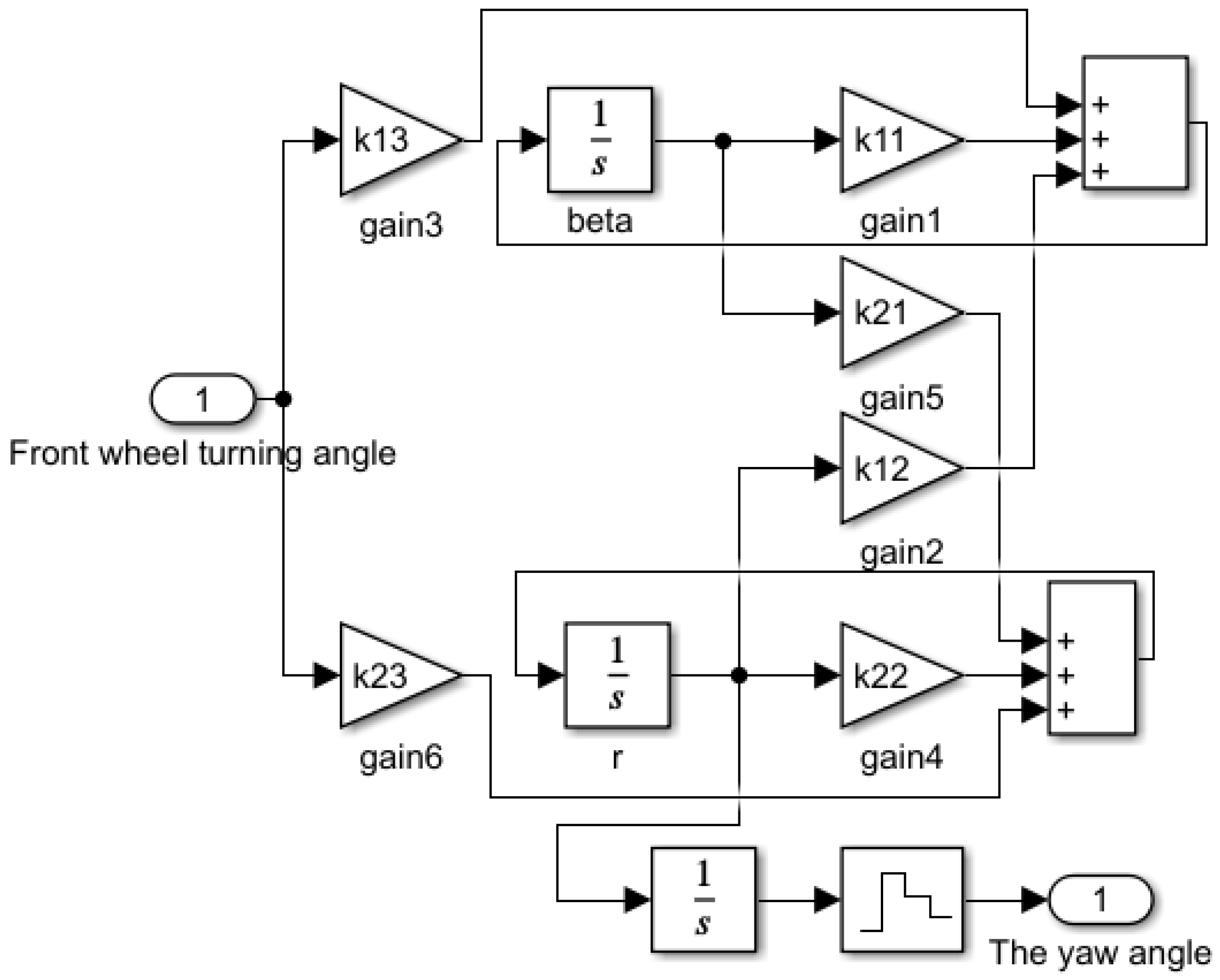
Based on these relationships, a relevant model was constructed in Simulink. The model uses two-degrees-of-freedom vehicle dynamics to determine the vehicle’s yaw angle. The input to the model is the steering wheel rotation angle, and the output is the camera rotation angle. Depending on the vehicle’s yaw angle, the camera adjusts its angle in various driving scenes. The model is illustrated in Figure 4 and Figure 5. The system sampling time is 0.04 s.

3. Camera Rotation Strategies in Different Scenes

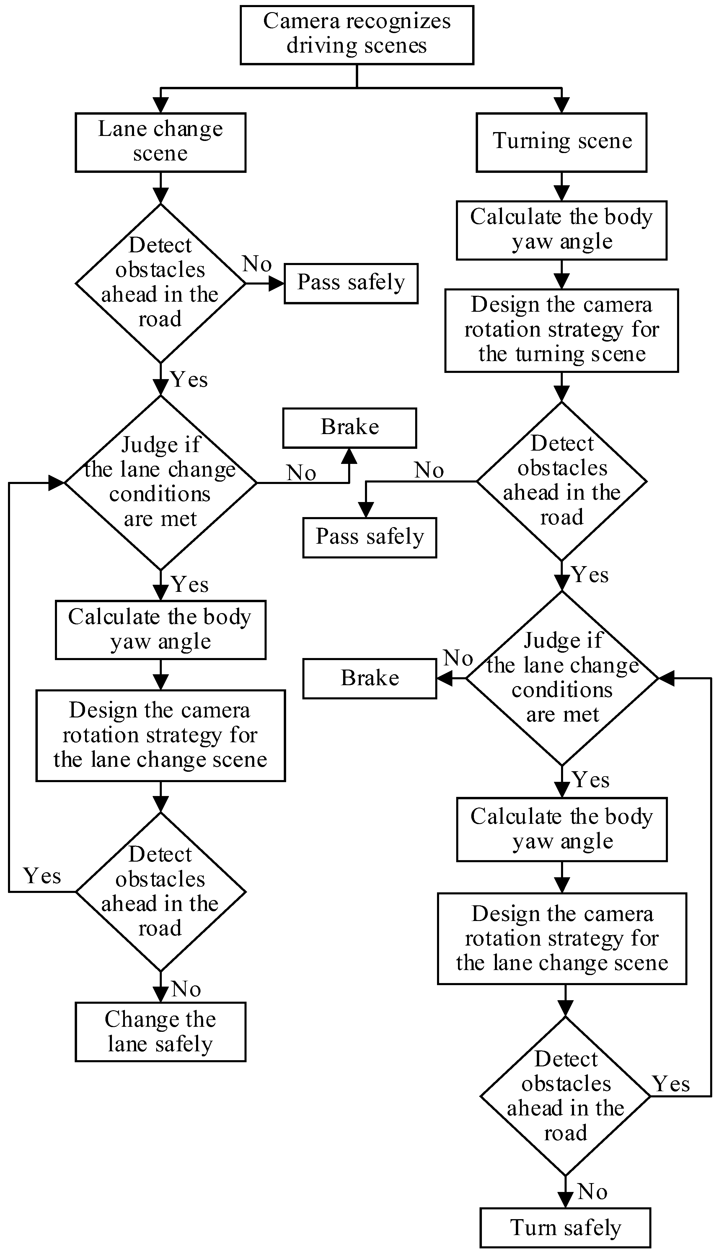
To design a camera rotation strategy for lane changing and turning behaviors, an environment perception model was built for different driving processes based on active monocular vision.

3.1. Lane-Change Scene

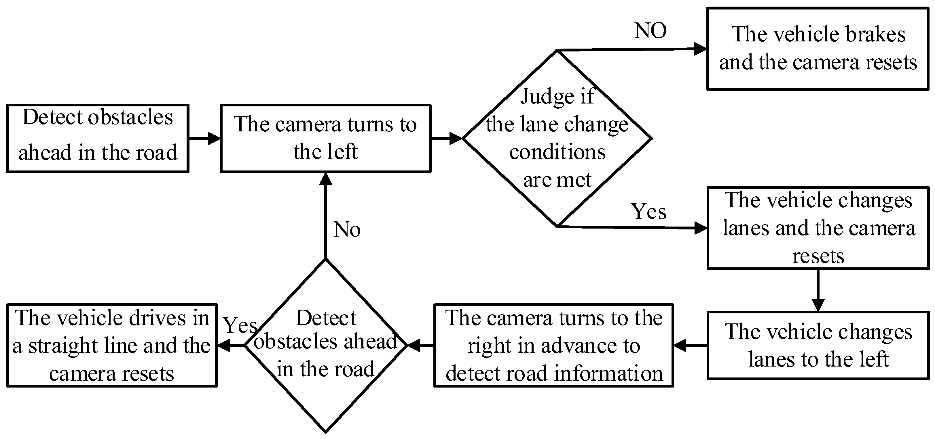
Considering the large number of influencing factors in the lane-changing process, the scene is first simplified appropriately. Assuming that the road is a unidirectional two-lane road and a horizontal straight road with curvature 0, only the case of changing lanes to the left is considered. The camera rotation strategy for the lane-change scene is shown in Figure 6.
Based on the above assumptions, the lane-change scene is established as shown in Figure 7:
In Figure 7, four stages of lane-change behavior are depicted. Before the vehicle changes lanes, it is denoted as A. After the lane change, it is denoted as A’. The self-driving vehicle A is driving at-speed on the highway when it encounters obstacle B in front of it. The two lanes are straight and the obstacle is stationary. The execution process of the lane-change behavior is as follows: self-driving vehicle A is driving in a straight line in the original lane, obstacle B exists in front of it and is detected by the monocular vision, and the active monocular vision determines that the driving environment is a lane-change scene, which achieves the vehicle’s obstacle avoidance.
Camera rotation strategy:
The on-board camera is denoted as camera l. Before initiating a lane change, the initial angle of the camera is 0. In this paper, we take the left-lane change as an example.
(1)
When an obstacle is detected on the road ahead: Camera l determines that the driving environment is a straight-ahead scene, detects obstacle B ahead in this lane, and further determines whether obstacle B is a pseudo-obstacle. If it is a pseudo-obstacle, it passes straight ahead, and if it is not, it makes an intention to change the lane.
(2)
Before the intent to change the lane is generated: Camera l ends the tracking of obstacle B, detects and observes the left lane, observes the left lane, determines whether the conditions for changing lanes are met, and then the camera resets. If it meets the lane-change conditions, it starts to change lanes, and brakes if it does not.
(3)
Left-lane-change phase: Camera l combines the vehicle system dynamic to compensate for the change in yaw angle by generating a rotation in the opposite direction to the vehicle body, and senses the information in front of the left lane in advance. The camera stops rotating accordingly to the yaw angle of the vehicle body when an obstacle is detected in front of the left lane, which in turn tracks the obstacle.
(4)
Straight-line phase: Camera l is reset and senses the road information ahead.

3.2. Turning Scene

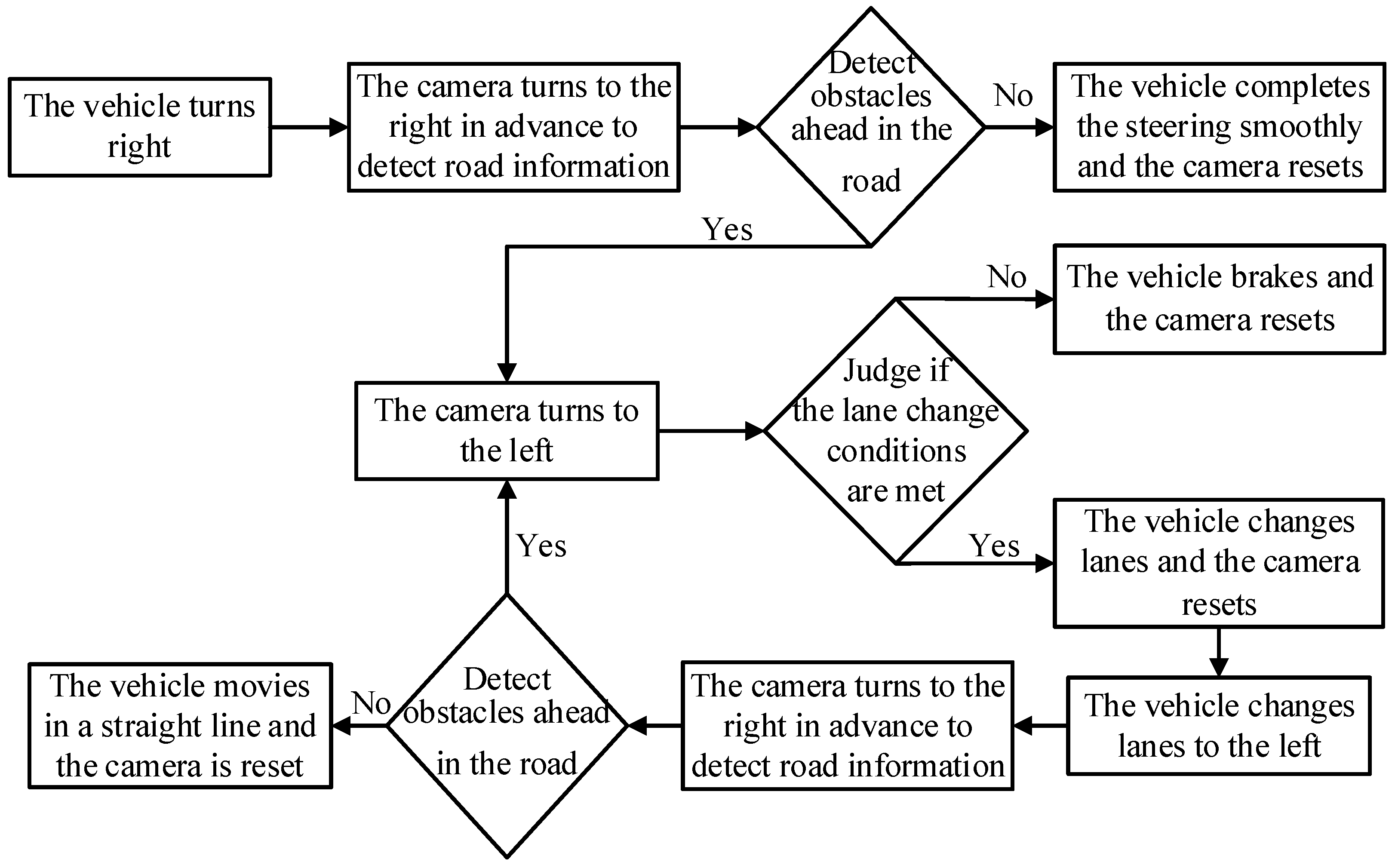
Considering the many influencing factors in the turning process, the scene is first simplified appropriately. It is assumed that the road is a unidirectional, two-lane road and the turning radius is not less than 8 m. In this case, it conforms to the two-degrees-of-freedom vehicle dynamic model, and only the case of turning to the right is considered. The camera rotation strategy for the turning scene is shown in Figure 8.
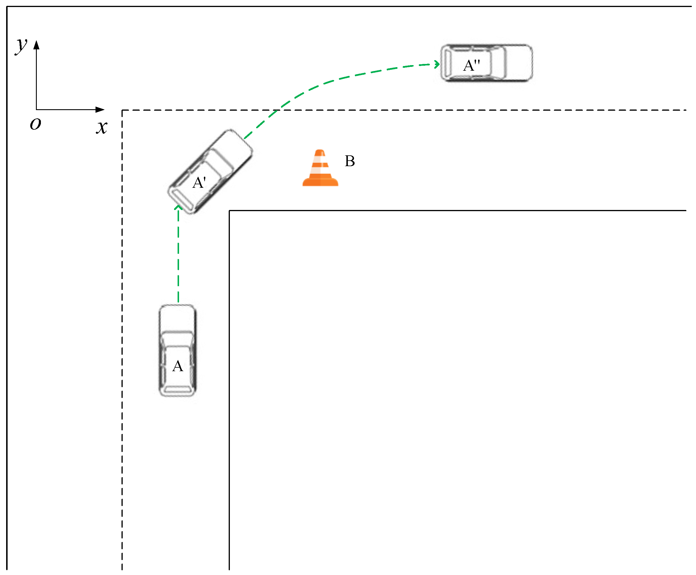
The turning scene is established based on the above assumptions, as shown in Figure 9.
In Figure 9, the four phases of turning behavior are illustrated. Before the vehicle makes a turn, it is denoted as A. During the turning, it is denoted as A’. After the turn is completed, it is denoted as A”. In the image, self-driving vehicle A is traveling on the road at speed, and is about to make a right turn. The two lanes are always straight except for right-angle bends, and there is a stationary obstacle. The execution process of the turning behavior is as follows: the self-driving vehicle A drives straight in the original lane and then turns right, the monocular vision detects the existence of obstacle B in front of the driving lane after turning, and the active monocular vision judges the driving environment as the turning scene to achieve the obstacle avoidance of the vehicle.
Camera rotation strategies:
The vehicle camera is denoted as camera l. The initial camera turn angle is 0 until a turning intention is generated, and in this paper, we take right turning as an example.
(1)
Right turning phase: Camera l judges the driving environment as a turning scene, and combines with the vehicle system dynamic to compensate for the yaw angle change by rotating in the same direction as the vehicle body, turning to the right in advance to detect the lane in which the vehicle will be traveling, and observing whether there is an obstacle in front of that lane.
(2)
When an obstacle is detected in the road ahead: Camera l detects in advance the existence of obstacle B in front of this lane and keeps tracking obstacle B. Camera l then detects whether the obstacle is a pseudo-obstacle, passes straight ahead if it is a pseudo-obstacle, and generates a lane-change intention if it is not.
(3)
Before generating the intention to change lanes: Camera l ends the tracking of obstacle B and detects the left lane to judge whether it meets the conditions for changing lanes, and then the camera resets. If it meets the lane-change conditions, it starts to change lanes, and if it does not, it brakes.
(4)
Left-lane-change phase: Camera l determines that the driving environment is a straight-line scene and combines with the vehicle system dynamic to compensate for the yaw angle change by generating a rotation in the opposite direction to the vehicle body, to sense the information in front of the left lane in advance. When an obstacle is found in front of the left lane, the camera does not rotate according to the vehicle body yaw angle and thus tracks the obstacle.
(5)
Straight driving phase: Camera l resets and senses the road information ahead.

4. Experimental Validation

The experiments in this paper consist of two parts: a simulation experiment and a real vehicle experiment in a controlled scene.

4.1. Simulation Experiment

In this paper, the effectiveness of the designed camera rotation strategy based on monocular active environment sensing is verified by the joint simulation experiment of Carsim and Simulink. The front-wheel rotation angle measured by Carsim is transferred to Simulink, and the required yaw angle is calculated by the two-degrees-of-freedom vehicle dynamic model, which in turn achieves the control of camera rotation.
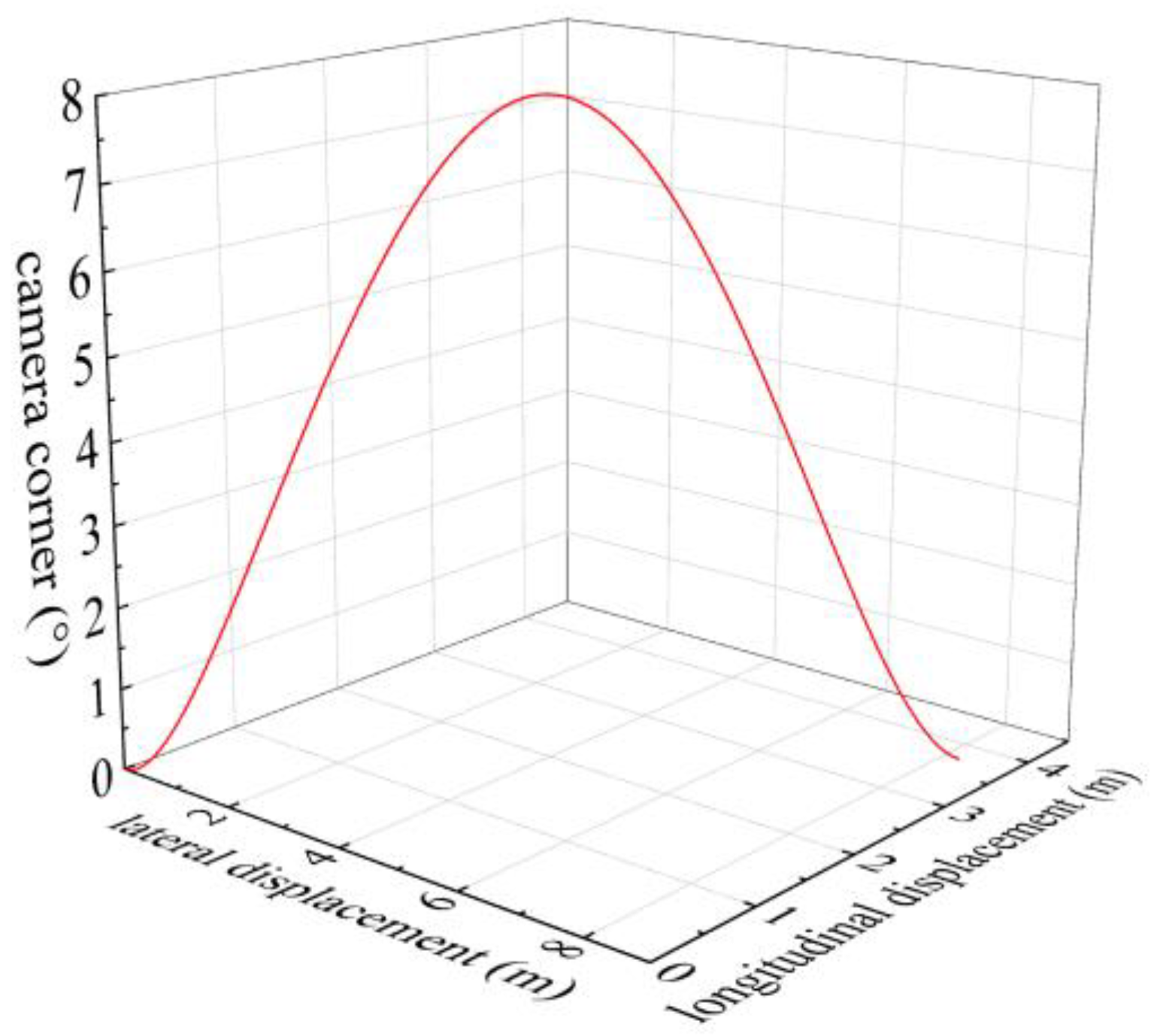
Figure 10 shows the relationship between the trajectory of the vehicle and the camera angle in the lane-change scene, with the horizontal coordinate representing the forward direction of the vehicle, i.e., the transverse displacement, and the vertical coordinate representing the direction of the vehicle’s lane change, i.e., the longitudinal displacement. It can be seen from Figure 10 that, with the increasing of the horizontal and longitudinal displacement of the vehicle, the camera turning angle increases from 0 and then decreases to 0, which is in line with the operation of the vehicle under the actual working conditions.
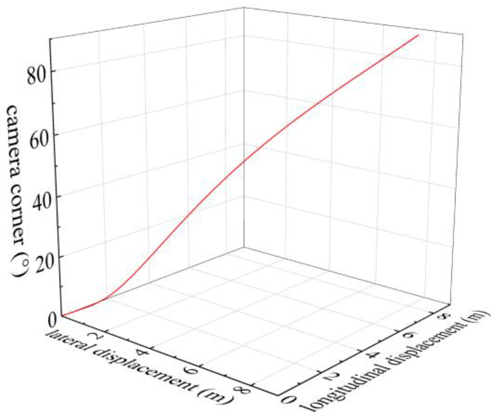
Figure 11 shows the relationship between the trajectory of the vehicle and the camera angle in the turning scene, with the horizontal coordinate representing the forward direction of the vehicle after turning, i.e., the transverse displacement, and the vertical coordinate representing the forward direction of the vehicle before turning, i.e., the longitudinal displacement. As can be seen from Figure 11, with the increasing transverse and longitudinal displacements of the vehicle, the camera turning angle changes from 0 to 90, which is in line with the operation of the vehicle under actual working conditions.
The feasibility of the camera rotation strategy method for active visual environment perception, as proposed in this paper, has been verified through simulation experiments. To further explore whether the effect of the method in real application scenes is in line with the results of the simulation experiments, real vehicle experiments are described in this paper.

4.2. Real Vehicle Experiment

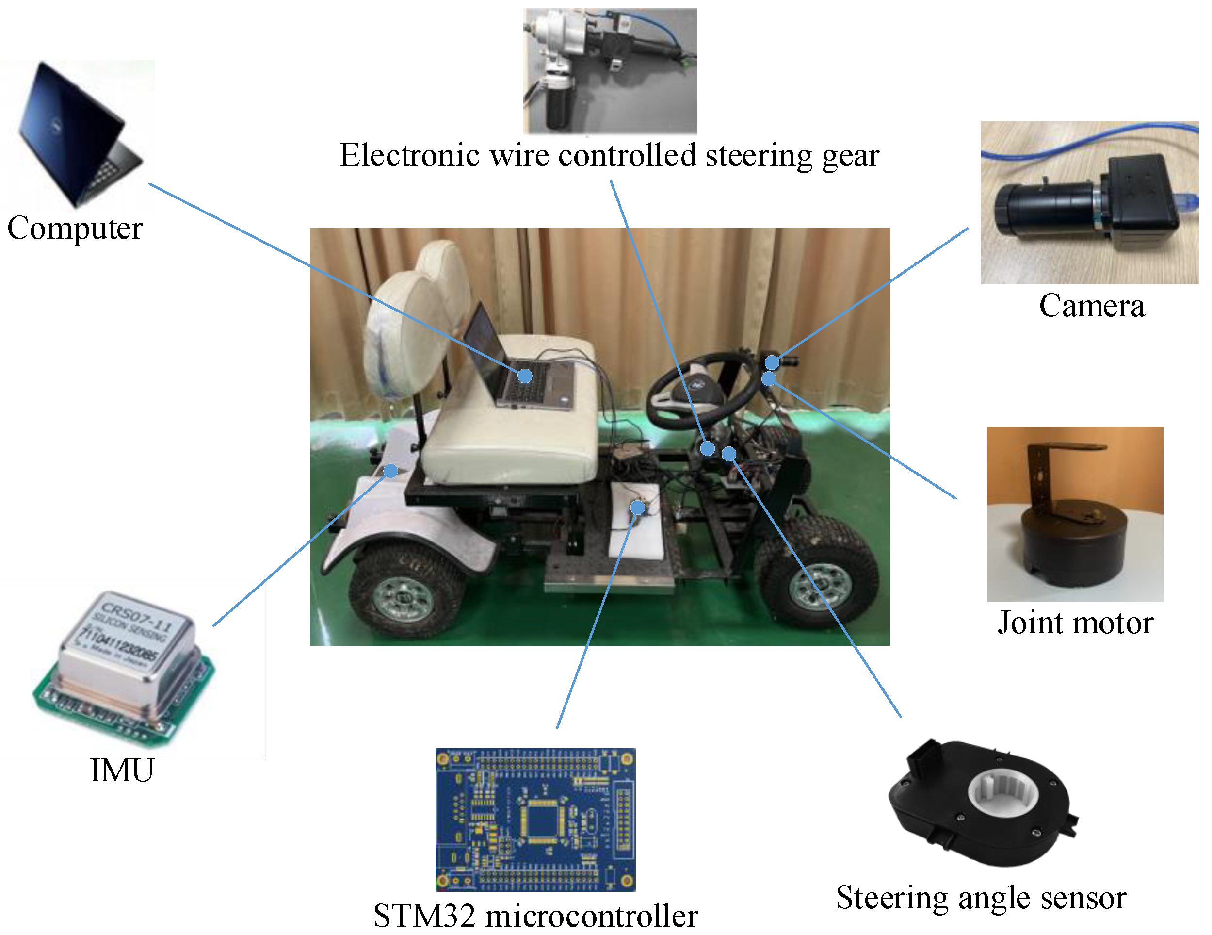
The experimental vehicle is based on a pure electric vehicle as a platform, which is equipped with experimental equipment such as cameras, articulated motors, IMU (inertial measurement unit), electronic steer-by-wire, laptop, microcontroller, steering angle sensor, and others. The related equipment is as follows:
An MV-VDF300SC industrial digital camera is installed on the vehicle as a monocular vision sensor, which is mounted on the centerline in the front of the vehicle through a joint motor at a height of 75 cm above the ground. The camera recognizes the obstacles it tracks every 0.04 s; the turning-angle sensor, mounted on the turning column, measures the turning angle of the front wheels and converts it into a digital signal to be sent to the vehicle’s control system, which adjusts the rotation angle of the camera according to this digital signal; an HEC295IMU is installed at the bottom of the experimental vehicle, which is used to locate and read the motion status of the vehicle in real time; the laptop is used as a computing unit to perform real-time data processing, and the microcontroller outputs PWM according to the signals sent by the computing unit to control the angle of the joint motors, so as to realize the rotation of the camera. The camera model incorporates a USB2.0 standard interface with the advantages of high resolution, high precision, and high definition. The camera parameters are shown in Table 1. The joint motor parameters are shown in Table 2. The schematic diagram of the experimental vehicle equipment is shown in Figure 12.
The front-wheel turning angle of the autonomous vehicle can be obtained from the turning-angle sensor, while the two-degrees-of-freedom vehicle dynamic model can obtain the yaw angle of the vehicle from this turning angle. In order to verify the feasibility and effectiveness of this study using actual road conditions, this paper carries out real vehicle experiments of lane changing and turning scenes based on the above principles.
In this paper, the resolution of the picture detected by the camera is 1600 × 1200. In the relationship of the distance of the obstacle from the center of the picture, because the width of the picture is 1600 pixels, the maximum value of the distance of the obstacle from the center of the picture is 800 pixels. The experiments in this paper take the upper left corner of the picture as the coordinate origin, with the right as the X-axis positive, and down as the Y-axis positive.

4.2.1. Lane-Change Scene Experiment

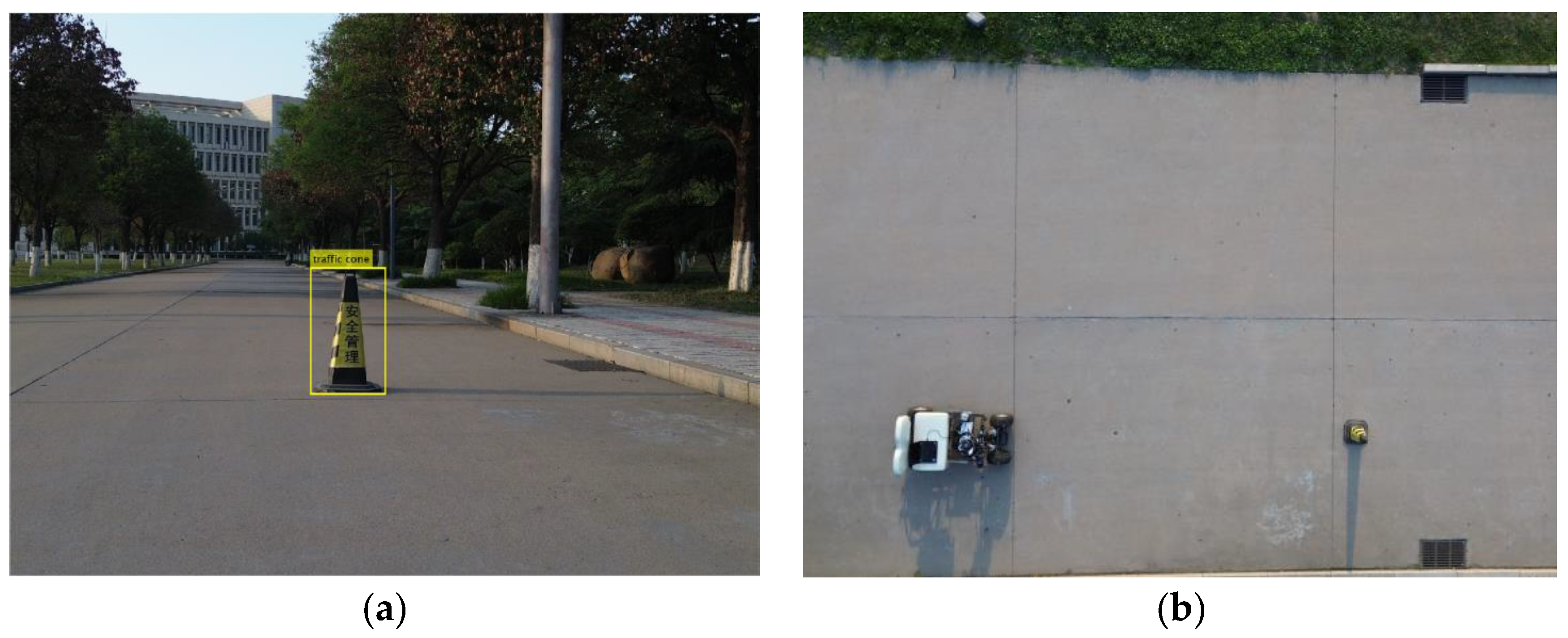
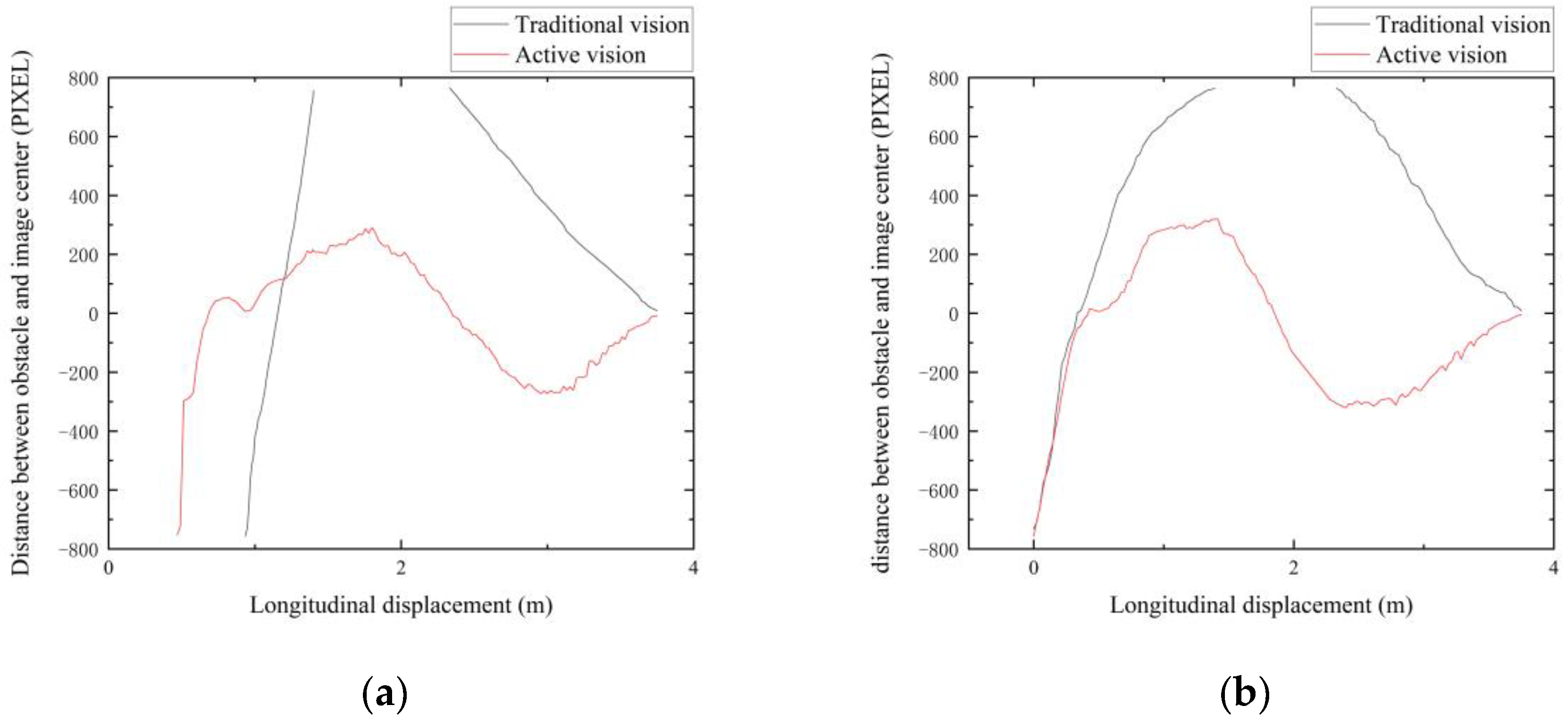
In this scene, the vehicle moves forward at 30 km/h and when an obstacle is detected in front of the home lane, the vehicle begins to change lanes. As the yaw angle of the vehicle changes, the camera rotates accordingly. When an obstacle is found in front of the lane the vehicle is about to enter, the camera tracks the obstacle. The selected experiment takes the difference in the position of the obstacle during the lane-changing process of the vehicle as a variable, and divides the position of the obstacle into two cases: the first case is that the obstacle is close to the vehicle, and the camera cannot detect the obstacle at the beginning of the lane-changing process of the vehicle (the obstacle is not in the detection range of the camera); the second case is that the camera can just detect the obstacle at the beginning of the lane-change process (the obstacle is at the edge of the detection range of the camera). In this study, the relationship between the longitudinal displacement of the vehicle and the distance between the center of the obstacle and the center of the picture in the obstacle information obtained by the camera when the vehicle changes lanes is verified by actual vehicle experiments. A diagram of the lane changing experiment scene is shown in Figure 13.
Figure 14 depicts a comparison between the traditional obstacle detection method and the improved method in a lane-change scene. The upper five images show the effect of obstacle detection for the improved method in this paper, while the lower five images show the effect for the conventional obstacle detection method. The two images in each column are at the same moment in the vehicle lane-change process. The images in the first column show the effect of obstacle detection when the vehicle starts changing lanes, and the images in the fifth column show the effect of obstacle detection when the vehicle finishes changing lanes. In addition to these two moments, we can clearly see that the improved method in this paper is better than the traditional obstacle detection method, and the traditional obstacle detection method will also lose the obstacle information, as shown in the third image.
While the vehicle is on the road, the camera will detect any obstacles ahead. If an obstacle is found, the system will recognize it as a lane-change scene and track the obstacle. If the obstacle is not a pseudo-obstacle, the vehicle starts changing lanes. Before the vehicle starts changing lanes, the camera scans the left side of the road to determine whether it meets the conditions for changing lanes. If the lane-change condition is satisfied, the corresponding camera rotation strategy is formulated.
By analyzing Figure 15a, it can be found that when the vehicle starts to change lanes in this case, i.e., when the longitudinal displacement of the vehicle is 0 m, the camera is unable to detect the information about obstacles existing in the road because the obstacles are not located in the detection range of the camera at the beginning of the lane change.
In the traditional visual obstacle detection method, the vehicle yaw angle increases as the vehicle changes lanes to the left. When the longitudinal displacement of the vehicle is 0.94 m, the camera detects the obstacle, and at this time the distance between the center of the obstacle and the center of the picture is −757 PIXEL. When the camera just detects the obstacles, the obstacles are all at the left edge of the picture, so the distance is negative. When the longitudinal displacement is 1.41 m, the distance of the obstacle center from the center of the picture is 756 PIXEL, and the camera loses the obstacle information. When the vehicle starts to drive into the left lane, the yaw angle of the vehicle decreases. When the longitudinal displacement of the vehicle is 2.33 m, the camera detects the obstacle, and at this time the distance between the center of the obstacle and the center of the picture is 751 PIXEL. In this case, when the camera detects the obstacles, the obstacles are all at the right edge of the picture, so the distance is positive. When the longitudinal displacement is 3.75 m, at this time the distance between the center of the obstacle and the center of the picture is 9 PIXEL, and the vehicle completes the lane-change process.
In the improved method of obstacle detection described in this paper, with the vehicle changing lanes to the left, the camera incorporates the vehicle system dynamic to compensate for the yaw angle change by generating a rotation opposite to that of the vehicle body so as to detect the presence of an obstacle in the left lane in advance. The camera detects the obstacle when the longitudinal displacement of the vehicle is 0.46 m. At this time, the distance between the center of the obstacle and the center of the picture is −753 PIXEL. In this case, when the camera just detects the obstacle, the obstacles are all at the left edge of the picture, so the distance is negative. The camera at this time rotates quickly to position the obstacle in the center of the picture and then tracks the obstacle. When the longitudinal displacement is 0.82 m, the distance between the center of the obstacle and the center of the picture is 52 PIXEL, and the camera rotates and overshoots. When the vertical displacement is 0.93 m, the distance between the center of the obstacle and the center of the picture is 6 PIXEL, and the camera starts to track the obstacle. When the longitudinal displacement of the vehicle is 0.93~1.80 m, the yaw angle of the vehicle becomes increasingly large as the vehicle starts to drive out of the current lane, so the distance fluctuation between the obstacle and the center of the picture increases gradually when the camera tracks the obstacle. Since the vehicle is rotating to the left at this time, the obstacle tends to move to the right when the camera is tracking the obstacle, so the obstacle is in the right half of the picture and the distance value is positive. When the longitudinal displacement of the vehicle is 1.80~2.99 m, the distance between the obstacle and the center of the picture changes from 291 PIXEL to −272.5 PIXEL. As the vehicle changes from turning to the left to turning to the right at this stage, the vehicle starts to move into the left lane. The obstacle then has a tendency to move to the left as the camera tracks the obstacle. So the obstacle is in the left half of the picture and the distance value is negative. When the longitudinal displacement of the vehicle is 2.99~3.75 m, the distance between the obstacle and the center of the picture changes from −272.5 PIXEL to −8 PIXEL at this time. This vehicle has moved into the left lane, and the vehicle yaw angle continues to decrease. So when the camera is tracking the obstacle, the fluctuation in the distance between the obstacle and the center of the picture is also decreases in size until the vehicle completes the lane-change process.
By analyzing Figure 15b, it can be found that in the case when the vehicle starts to change lanes, i.e., when the longitudinal displacement of the vehicle is 0, the obstacle is at the edge of the detection range of the camera, and the camera is just able to detect the obstacle.
In the traditional method for visual obstacle detection, the yaw angle of the vehicle increases as the vehicle changes lanes to the left. When the longitudinal displacement of the vehicle is 0 m, the camera detects the obstacle, and at this time the distance between the center of the obstacle and the center of the picture is −732 PIXEL. In this case, when the camera has just detected the obstacle, the obstacles are all at the left edge of the picture, so the distance is negative. When the longitudinal displacement is 1.39 m, the distance of the obstacle center from the center of the picture is 764 PIXEL, and the camera loses the obstacle information. When the vehicle starts to drive into the left lane, the yaw angle of the vehicle continuously decreases. The camera detects the obstacle when the longitudinal displacement of the vehicle is 2.32 m. The distance between the center of the obstacle and the center of the picture is 764 PIXEL. In this case, when the camera detects the obstacles, the obstacles are all at the right edge of the picture, so the distance is positive. When the longitudinal displacement is 3.75 m, at this time the distance between the center of the obstacle and the center of the picture is 9 PIXEL, and the vehicle completes the lane-change process.
In the improved method of obstacle detection described in this paper, the camera detects the obstacle when the longitudinal displacement of the vehicle is 0 m. At this time, the distance between the center of the obstacle and the center of the picture is −757 PIXEL. In this case, when the camera just detects the obstacles, the obstacles are all at the left edge of the picture, so the distance is negative. At this time, the camera rotates quickly so that the obstacles are in the center of the picture and the obstacles are tracked. When the longitudinal displacement is 0.43 m, the distance between the center of the obstacle and the center of the picture is 15 PIXEL, and the camera rotates and overshoots. When the longitudinal displacement is 0.5 m, the distance between the center of the obstacle and the center of the picture is 6 PIXEL, the camera starts to track the obstacle. When the longitudinal displacement of the vehicle is 0.5~1.41 m, the yaw angle of the vehicle becomes increasingly larger as the vehicle starts to drive out of the current lane, so when the camera is tracking the obstacle, the fluctuation in the distance between the obstacle and the center of the picture also increases gradually. At this point, the vehicle is turning to the left, so the obstacle has a tendency to move to the right when the camera is tracking it. So the obstacle is in the right half of the picture and the distance value is positive. When the longitudinal displacement of the vehicle is 1.41~2.4 m, the distance between the obstacle and the center of the picture changes from 320 PIXEL to −320.5 PIXEL. At this stage, the vehicle turns from turning to the left to turning to the right, and the vehicle starts to move into the left lane. When the camera is tracking the obstacle, the obstacle has a tendency to move to the left, so the obstacle is in the left half of the picture and the distance value is negative. When the longitudinal displacement of the vehicle is 2.4~3.75 m, the distance between the obstacle and the center of the picture changes from −320.5 PIXEL to −5.5 PIXEL. The vehicle has moved into the left lane, and the yaw angle of the vehicle continues to decrease, so the fluctuation in the distance between the obstacle and the center of the picture gradually becomes smaller when the camera is tracking the obstacle until the vehicle completes the lane-change process.

4.2.2. Turning Scene Experiment

In this scene, the vehicle moves forward at 15 km/h. First, the camera detects the current environment as a turning scene. As the vehicle begins to turn, the camera rotates after the yaw angle changes to detect the information of obstacles existing in real time on the road. When an obstacle is found in front of the lane the vehicle is about to enter, the camera tracks the obstacle. The selected experiment takes the difference in the position of the obstacle during the turning of the vehicle as a variable, and divides the position of the obstacle into two cases: the first case is that the camera can just detect the obstacle at the beginning of the turning process of the vehicle (the obstacle is at the edge of the detection range of the camera); the second case is that the obstacle is close to the vehicle, and the camera cannot detect the obstacle at the beginning of the turning process of the vehicle (the obstacle is not in the detection range of the camera). In this study, the relationship between the longitudinal displacement of the vehicle and the distance between the center of the obstacle and the center of the picture in the obstacle information obtained by the camera when the vehicle turns is verified by actual vehicle experiments. A diagram of the turning experiment scene is shown in Figure 16.
In Figure 17, a comparison is presented between the conventional obstacle detection method and the improved method in a turning scene. The upper five images show the obstacle detection effect of the improved method described in this paper, while the lower five images show the effect of the conventional obstacle detection method. The two images in each column are at the same moment in the vehicle turning process. The images in the first column show the effect of obstacle detection when the vehicle starts turning, while the images in the fifth column show the effect of obstacle detection when the vehicle finishes turning. In addition to these two moments, we can clearly see that the improved method described in this paper is better than the traditional obstacle detection method, and the traditional obstacle detection method will also lose the obstacle information, as shown in the third image.
When the vehicle is traveling on the road, the camera detects that the front is about to turn and identifies the scene as a turning scene, and then the camera rotation strategy is formulated accordingly. As the vehicle turns to the right, the camera compensates for the change in the yaw angle by rotating in the same direction as the vehicle body in conjunction with the vehicle system dynamic to detect in advance the road information after the turn.
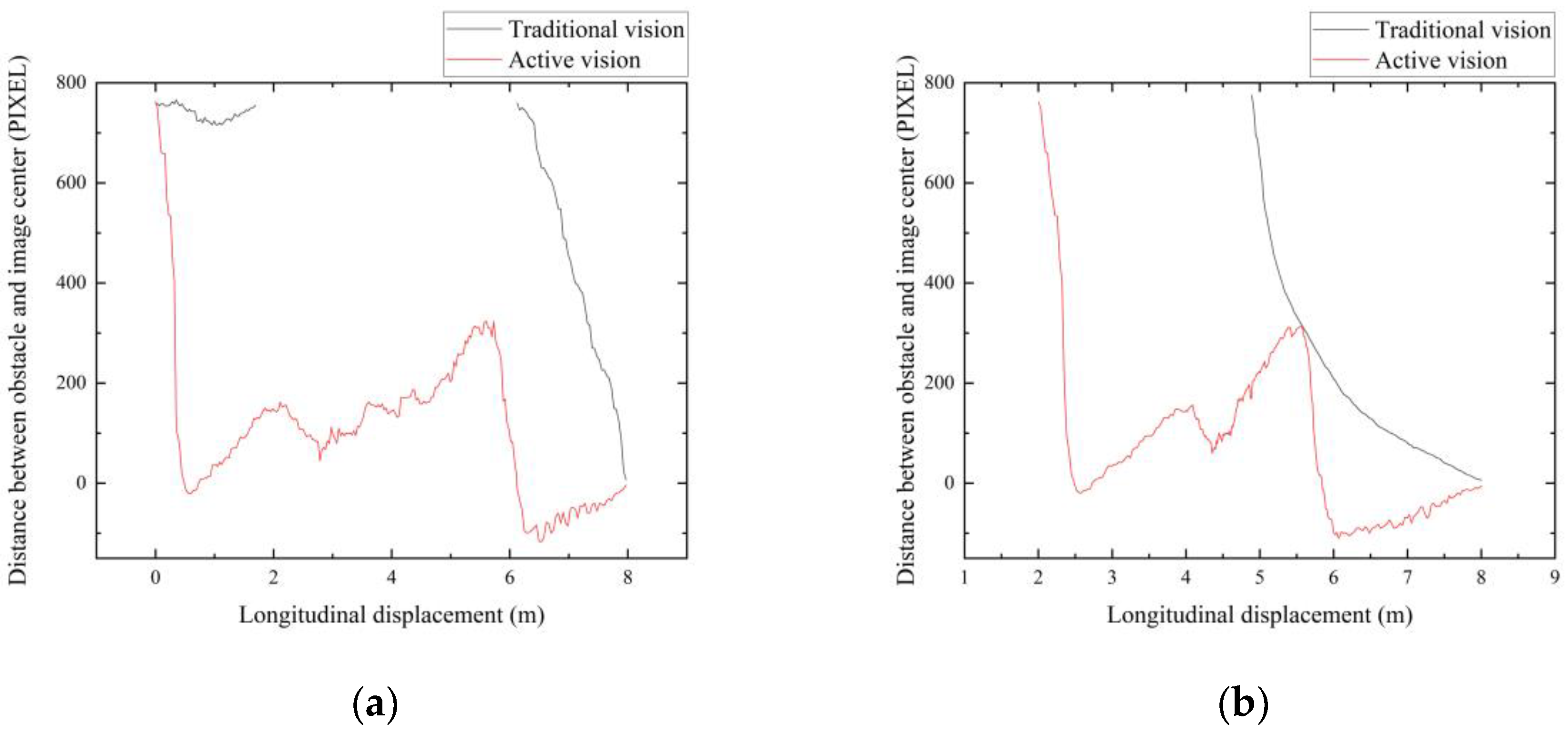
By analyzing Figure 18a, it can be found that when the vehicle starts to turn in that case, i.e., when the longitudinal displacement of the vehicle is 0, the obstacle is at the edge of the detection range of the camera, and the camera is just able to detect the obstacle.
In the traditional visual obstacle detection method, when the longitudinal displacement of the vehicle is 0, the camera detects the obstacle, and at this time the distance between the center of the obstacle and the center of the picture is 758 PIXEL. In this case, when the camera detects the obstacles, the obstacles are all at the right edge of the picture, so the distance is positive. When the longitudinal displacement is 1.69 m, at this time the distance between the center of the obstacle and the center of the picture is 755 PIXEL. The camera loses the obstacle information because of the large change in longitudinal displacement of the vehicle and the small change in the yaw angle at this time. When the change in the longitudinal displacement of the vehicle is small and the change in the angle of the yaw is large, i.e., when the longitudinal displacement of the vehicle is 6.12 m, the camera detects the obstacle, and at this time the distance between the center of the obstacle and the center of the picture is 760 PIXEL. In this case, when the camera detects the obstacles, the obstacles are all at the right edge of the picture, so the distance is positive. When the vehicle begins to turn into the lane ahead, the yaw angle of the vehicle continues to decrease. When the longitudinal displacement is 8 m, the distance between the center of the obstacle and the center of the picture is 7 PIXEL, at which time the vehicle completes the turning process.
In the improved method of obstacle detection described in this paper, the camera detects the obstacle when the longitudinal displacement of the vehicle is 0 m. At this time, the distance between the center of the obstacle and the center of the picture is 762 PIXEL. At this time, the camera rotates quickly so that the obstacles are in the center of the picture and the obstacles are tracked. When the longitudinal displacement is 0.57 m, the distance between the center of the obstacle and the center of the picture is −20.5 PIXEL, and the camera rotates and overshoots. When the longitudinal displacement is 0.76 m, the distance between the center of the obstacle and the center of the picture is 8 PIXEL, the camera starts to track the obstacle. When the longitudinal displacement of the vehicle is 0.76~2.11 m, the distance between the obstacle and the center of the picture changes from 8 PIXEL to 162 PIXEL. Since the vehicle yaw angle is basically unchanged at this time and the longitudinal displacement changes more, the distance between the center of the obstacle and the center of the picture fluctuates increasingly more when the camera is tracking the obstacle. At this stage, when the camera is tracking the obstacle, the obstacle has a tendency to move to the right, so the obstacle is in the right half of the picture and the distance value is positive. As the vehicle’s turning process proceeds, the vehicle’s yaw angle begins to change, so when the longitudinal displacement of the vehicle is 2.11~2.78 m, the distance between the obstacle and the center of the picture changes from 162 PIXEL to 45 PIXEL. When the longitudinal displacement of the vehicle is 2.78~5.72 m, the distance between the obstacle and the center of the picture changes from 45 PIXEL to 323.5 PIXEL. Since at this time the vehicle yaw angle change is increasingly larger and the longitudinal displacement change is diminishing, but the magnitude of the vehicle yaw angle change is still smaller than the magnitude of the longitudinal displacement change, so the distance of the obstacle center from the center of the picture is positive. When the longitudinal displacement of the vehicle is 5.72~6.53 m, the distance between the obstacle and the center of the picture changes from 323.5 PIXEL to −117 PIXEL. At this time, the vehicle begins to turn into the lane ahead and the longitudinal displacement of the vehicle is basically unchanged, and the vehicle moves toward the right side of the rotation, so the camera tracking the obstacle has a tendency to move to the left, so the obstacle is in the left part of the picture, the distance value changes from a positive value to a negative value. When the longitudinal displacement of the vehicle is 6.53~8 m, the distance between the obstacle and the center of the picture changes from −117 PIXEL to −4 PIXEL. At this point, the vehicle has been turning into the lane ahead, the longitudinal displacement of the vehicle is basically unchanged, and the vehicle is turning to the right, so the fluctuation in the distance between the obstacle and the center of the picture diminishes while the camera is tracking the obstacle, until the vehicle completes the turning process.
By analyzing Figure 18b, it can be found that when the vehicle starts to turn in this case, i.e., when the longitudinal displacement of the vehicle is 0 m, the camera is unable to detect the information about obstacles existing in the road because the obstacles are not located in the detection range of the camera at the beginning of the turn.
In the traditional visual obstacle detection method, in the first half of the turning process of the vehicle, the longitudinal change in the vehicle is large and the change in the yaw angle is small, so the camera cannot detect the obstacle. When the longitudinal displacement of the vehicle is 4.9 m, the camera detects the obstacle, and at this time the distance between the center of the obstacle and the center of the picture is 755 PIXEL. In this case, when the camera detects the obstacles, the obstacles are all at the right edge of the picture, so the distance is positive. At this point, the vehicle begins to turn into the lane ahead, and the vehicle’s yaw angle changes more, so the distance between the center of the obstacle and the center of the picture decreases more quickly. When the vehicle begins to turn into the lane ahead, the yaw angle of the vehicle decreases. When the longitudinal displacement is 8 m, the distance between the center of the obstacle and the center of the picture is 6 PIXEL, at which time the vehicle completes the turning process. At this point, the vehicle has been turning into the lane ahead, the vehicle’s yaw angle change is smaller, so the distance between the center of the obstacle and the center of the picture decreases more slowly.
In the improved method of obstacle detection described in this paper, with the vehicle turning to the right, the camera incorporates the vehicle system dynamic to compensate for the yaw angle change by generating a rotation opposite to that of the vehicle body so as to detect in advance the presence of an obstacle in the left lane. The camera detects the obstacle when the longitudinal displacement of the vehicle is 2 m. At this time, the distance between the center of the obstacle and the center of the picture is 762 PIXEL. At this time, the camera rotates quickly so that the obstacles are in the center of the picture and the obstacles are tracked. When the longitudinal displacement is 2.57 m, the distance between the center of the obstacle and the center of the picture is −20 PIXEL, and the camera rotates and overshoots. When the longitudinal displacement is 2.83 m, the distance between the center of the obstacle and the center of the picture is 11 PIXEL, the camera starts to track the obstacle. When the longitudinal displacement of the vehicle is 2.83~4.08 m, the distance between the obstacle and the center of the picture changes from 11 PIXEL to 156.5 PIXEL. Since the vehicle yaw angle is basically unchanged at this time and the longitudinal displacement changes more, the distance between the center of the obstacle and the center of the picture fluctuates increasingly more when the camera is tracking the obstacle. At this stage, when the camera is tracking the obstacle, then the obstacle has a tendency to move to the right, so the obstacle is in the right half of the picture and the distance value is positive. As the vehicle’s turning process proceeds, the vehicle’s yaw angle begins to change, so when the longitudinal displacement of the vehicle is 4.08~4.35 m, the distance between the obstacle and the center of the picture changes from 156.5 PIXEL to 60 PIXEL. When the longitudinal displacement of the vehicle is 4.35~5.55 m, the distance between the obstacle and the center of the picture changes from 60 PIXEL to 313 PIXEL. Since at this time the vehicle yaw angle change is continuously increasing and the longitudinal displacement change is diminishing, but the magnitude of the vehicle yaw angle change is still smaller than the magnitude of the longitudinal displacement change, the distance of the obstacle center from the center of the picture is positive. When the longitudinal displacement of the vehicle is 5.55~6.07 m, the distance between the obstacle and the center of the picture changes from 313 PIXEL to −110 PIXEL. At this time, the vehicle begins to turn into the lane ahead, the longitudinal displacement of the vehicle is basically unchanged, and the vehicle moves toward the right side of the rotation, so the camera tracking the obstacle will have a tendency to move to the left, so the obstacle is in the left part of the picture, the distance value changes from a positive value to a negative value. When the longitudinal displacement of the vehicle is 6.07~8 m, the distance between the obstacle and the center of the picture changes from −110 PIXEL to −5 PIXEL. At this point, the vehicle has been turning into the lane ahead, the longitudinal displacement of the vehicle is basically unchanged, and the vehicle is turning to the right, so the fluctuation in the distance between the obstacle and the center of the picture diminishes when the camera is tracking the obstacle, until the vehicle completes the turning process.
5. Conclusions

The experiments in this paper confirm that the traditional visual obstacle detection method has limitations. When a vehicle changes lanes or turns, due to the constant change in the body yaw angle and the limited detection range of the camera, the camera cannot always detect the effective information of the obstacle. As a result, the obstacle information will be lost at some moments. However, compared to the traditional method, when the vehicle starts to change lanes or turn, the obstacle is not in the detection range of the camera; the method used in this paper can detect the obstacle on the road earlier than the traditional vision method, and the obstacle is always near the center of the camera, and the camera can accurately and effectively detect the obstacle information.
The results presented here aim to mitigate the problems of visual blind area and incomplete environment perception of traditional monocular vision in vehicle lane-changing and turning scenes:
(1)
Based on the two-degrees-of-freedom vehicle dynamic model, the camera angle is adjusted in real time by the camera control model according to the front-wheel turning angle of the vehicle, which solves the problem of limited detection range and blind area in the field of view of traditional monocular vision.
(2)
Camera rotation strategies in lane changing as well as turning scenes are designed to determine the camera rotation strategy by the camera recognizing different driving scenes, which improves the broadness of the application.
(3)
The method proposed in this paper is validated through simulation experiments and actual vehicle experiments. The experimental results indicate that in lane changing and turning scenes, the active monocular visual environment sensing method described in this paper, compared with the traditional monocular visual environment sensing method, improves the sensing range by using an active camera to achieve the threshold change. Combined with the vehicle dynamic model, it solves the problem of the visual field blindness that exists in the vehicle when changing lanes or turning. The real-time rotation of the camera ensures that the camera will not lose the obstacle information, which can be used to accurately and effectively detect the obstacle and ensure the safe driving of the vehicle.

Author Contributions

Conceptualization, X.K., S.S. (Shuyue Shi), J.N., D.G. and Y.X.; methodology, X.K., S.S. (Shuyue Shi), J.N., D.G. and Y.X.; software, X.K., S.S. (Shuyue Shi), S.S. (Shuzhe Si), J.N., D.G., P.W., L.W. and Y.X.; Formal analysis, X.K., S.S. (Shuyue Shi), J.N., D.G. and Y.X.; writing—review and editing, X.K., S.S. (Shuyue Shi), B.Y., S.S. (Shuzhe Si), J.N., D.G., L.W. and Y.X.; visualization, S.S. (Shuyue Shi); validation, B.Y., S.S. (Shuzhe Si) and P.W.; investigation, B.Y., S.S. (Shuzhe Si) and P.W.; data curation, B.Y., S.S. (Shuzhe Si), P.W. and L.W.; supervision, B.Y., S.S. (Shuzhe Si), P.W., and L.W.; writing—original draft, X.K. and Y.X.; visualization, X.K. and Y.X.; project administration, X.K. and Y.X. All authors have read and agreed to the published version of the manuscript.

Funding

This work is supported by the Shandong Province Major Science and Technology Innovation Project (2023CXGC010111), Shandong Province Youth Innovation Team Plan for Universities (2023KJ153), Small and Medium-Sized Enterprise Innovation Capability Improvement Project (2022TSGC2277), Intelligent Automotive Sensor Technology Graduate Project (4053223015), Shandong Provincial Program of Introducing and Cultivating Talents of Discipline to Universities (4012322006), Natural Science Foundation of Shandong Province (ZR2022MF230), National Natural Science Foundation of China (52102465), and Experiment Technology Upgrading Project (2022003).

Data Availability Statement

The original contributions presented in the study are included in the article, further inquiries can be directed to the corresponding author/s.

Conflicts of Interest

The authors declare no conflicts of interest. The funders had no role in the design of the study; in the collection, analyses, or interpretation of data; in the writing of the manuscript; or in the decision to publish the results.

References

  1. Nwakanma, C.I.; Ahakonye, L.A.C.; Njoku, J.N.; Odirichukwu, J.C.; Okolie, S.A.; Uzondu, C.; Ndubuisi Nweke, C.C.; Kim, D.-S. Explainable artificial intelligence (xai) for intrusion detection and mitigation in intelligent connected vehicles: A review. Appl. Sci. 2023, 13, 1252. [Google Scholar] [CrossRef]
  2. Parekh, D.; Poddar, N.; Rajpurkar, A.; Chahal, M.; Kumar, N.; Joshi, G.P.; Cho, W. A review on autonomous vehicles: Progress, methods and challenges. Electronics 2022, 11, 2162. [Google Scholar] [CrossRef]
  3. Liu, F.; Lu, Z.; Lin, X. Vision-based environmental perception for autonomous driving. Proc. Inst. Mech. Eng. Part D J. Automob. Eng. 2022, 09544070231203059. [Google Scholar] [CrossRef]
  4. Pan, M.; Meng, C.; Tian, F.-P.; Feng, W. Graph Matching Based Robust Line Segment Correspondence for Active Camera Relocalization. In Proceedings of the Pattern Recognition and Computer Vision: 4th Chinese Conference, PRCV 2021, Beijing, China, 29 October–1 November 2021; pp. 228–238. [Google Scholar]
  5. Xu, N.; Huo, C.; Zhang, X.; Cao, Y.; Meng, G.; Pan, C. Dynamic camera configuration learning for high-confidence active object detection. Neurocomputing 2021, 466, 113–127. [Google Scholar]
  6. Kyrkou, C. C3 Net: End-to-end deep learning for efficient real-time visual active camera control. J. Real-Time Image Proc. 2021, 18, 1421–1433. [Google Scholar]
  7. Casao, S.; Serra-Gómez, Á.; Murillo, A.C.; Böhmer, W.; Alonso-Mora, J.; Montijano, E. Distributed multi-target tracking and active perception with mobile camera networks. Comput. Vis. Image Underst. 2024, 238, 103876. [Google Scholar]
  8. Zhang, Q.; Feng, W.; Shi, Y.-B.; Lin, D. Fast and robust active camera relocalization in the wild for fine-grained change detection. Neurocomputing 2022, 495, 11–25. [Google Scholar]
  9. Dai, X.-Y.; Meng, Q.-H.; Jin, S.; Liu, Y.-B. Camera view planning based on generative adversarial imitation learning in indoor active exploration. Appl. Soft Comput. 2022, 129, 109621. [Google Scholar]
  10. Guan, R.; Hu, G. Formation tracking of mobile robots under obstacles using only an active RGB-D camera. IEEE Trans. Ind. Electron. 2023, 71, 4049–4058. [Google Scholar]
  11. Oh, X.; Lim, R.; Foong, S.; Tan, U.-X. Marker-Based Localization System Using an Active PTZ Camera and CNN-Based Ellipse Detection. IEEE/ASME Trans. Mechatron. 2023, 28, 1984–1992. [Google Scholar]
  12. Kakaletsis, E.; Nikolaidis, N. Using synthesized facial views for active face recognition. Mach. Vis. Appl. 2023, 34, 62. [Google Scholar]
  13. Hu, J.; Pagilla, P.R. View planning for object pose estimation using point clouds: An active robot perception approach. IEEE Robot. Autom. Lett. 2022, 7, 9248–9255. [Google Scholar]
  14. Wei, X.; Xiao, C. MVAD: Monocular vision-based autonomous driving distance perception system. In Proceedings of the Third International Conference on Computer Vision and Data Mining (ICCVDM 2022), Hulun Buir, China, 19–21 August 2022; pp. 258–263. [Google Scholar]
  15. Martínez-Díaz, S. 3D distance measurement from a camera to a mobile vehicle, using monocular vision. J. Sens. 2021, 2021, 5526931. [Google Scholar]
  16. Liu, Y.; Sun, P.; Namiki, A. Target tracking of moving and rotating object by high-speed monocular active vision. IEEE Sens. J. 2020, 20, 6727–6744. [Google Scholar]
  17. Kim, M.; Kim, J.; Jung, M.; Oh, H. Towards monocular vision-based autonomous flight through deep reinforcement learning. Expert Syst. Appl. 2022, 198, 116742. [Google Scholar]
  18. Kim, I.S.; Kim, H.; Lee, S.; Jung, S.K. HeightNet: Monocular Object Height Estimation. Electronics 2023, 12, 350. [Google Scholar] [CrossRef]
  19. Dang, T.-V.; Bui, N.-T. Obstacle avoidance strategy for mobile robot based on monocular camera. Electronics 2023, 12, 1932. [Google Scholar] [CrossRef]
  20. Chuang, H.-M.; He, D.; Namiki, A. Autonomous target tracking of UAV using high-speed visual feedback. Appl. Sci. 2019, 9, 4552. [Google Scholar] [CrossRef]
  21. Wenning, M.; Backhaus, A.A.; Adlon, T.; Burggräf, P. Testing the reliability of monocular obstacle detection methods in a simulated 3d factory environment. J. Intell. Manuf. 2022, 33, 2157–2165. [Google Scholar]
  22. Sakagawa, Y.; Nakajima, K.; Ohashi, G. Vision based nighttime vehicle detection using adaptive threshold and multi-class classification. IEICE Trans. Fundam. Electron. Commun. Comput. Sci. 2019, 102, 1235–1245. [Google Scholar]
  23. Venkateswaran, N.; Hans, W.J.; Padmapriya, N. Deep learning based robust forward collision warning system with range prediction. Multimed. Tools Appl. 2021, 80, 20849–20867. [Google Scholar]
Figure 1. System workflow diagram.
Actuators 13 00317 g001
Figure 2. Diagram of the two-degrees-of-freedom vehicle dynamic model.
Actuators 13 00317 g002
Figure 3. (a) Diagram of the two-degrees-of-freedom vehicle dynamic model; (b) center-of-mass velocity decomposition diagram; (c) front-wheel speed decomposition diagram.
Actuators 13 00317 g003
Figure 4. Camera rotation angle acquisition model.
Actuators 13 00317 g004
Figure 5. Camera rotation angle acquisition model subsystem.
Actuators 13 00317 g005
Figure 6. Camera rotation strategy for the lane-change scene.
Actuators 13 00317 g006
Figure 7. Schematic diagram of the lane-change scene.
Actuators 13 00317 g007
Figure 8. Camera rotation strategy for the turning scene.
Actuators 13 00317 g008
Figure 9. Schematic diagram of the turning scene.
Actuators 13 00317 g009
Figure 10. Relationship between vehicle trajectory and camera angle in the lane-change scene.
Actuators 13 00317 g010
Figure 11. Relationship between vehicle trajectory and camera angle in the turning scene.
Actuators 13 00317 g011
Figure 12. Diagram of the experimental vehicle equipment.
Actuators 13 00317 g012
Figure 13. Lane changing experimental scene images: (a) main view (first view of the car camera); (b) bird’s-eye view (top view of the experimental scene taken by a drone).
Actuators 13 00317 g013
Figure 14. Comparison images of the obstacle detection effect in lane-change scenes.
Actuators 13 00317 g014
Figure 15. Diagram of the relationship between the distance from the center of the obstacle to the center of the image and the longitudinal displacement of the vehicle: (a) obstacles closer to the vehicle (the obstacle is not in the detection range of the camera); (b) obstacles far from the vehicle (the obstacle is at the edge of the detection range of the camera).
Actuators 13 00317 g015
Figure 16. Turning experimental scene images: (a) main view (first view of the car camera); (b) bird’s-eye view (top view of the experimental scene taken by a drone).
Actuators 13 00317 g016
Figure 17. Comparison images of the obstacle detection effect in the turning scenes.
Actuators 13 00317 g017
Figure 18. Diagram of the relationship between the distance from the center of the obstacle to the center of the image and the longitudinal displacement of the vehicle: (a) obstacles closer to the vehicle (the obstacle is at the edge of the detection range of the camera); (b) obstacles far from the vehicle (the obstacle is not in the detection range of the camera).
Actuators 13 00317 g018
Table 1. Performance parameters of the RER-USB8MP02G camera.
Camera PerformanceCamera Parameters
Resolution1024 × 768
Frame Rate30 fps
Sensitivity0.65 V/lux-sec@550 nm
Field of View60°
Operating Temperature−10–70 °C
Operating Voltage5 V
Operating Current120–220 mA
Minimum Illumination0.051 lux-
Table 2. Performance parameters of the joint motor.
Joint Motor PerformanceJoint Motor Parameters
Input Voltage12 V
Electric Current2 A
Speed1250 RPM
Disclaimer/Publisher’s Note: The statements, opinions and data contained in all publications are solely those of the individual author(s) and contributor(s) and not of MDPI and/or the editor(s). MDPI and/or the editor(s) disclaim responsibility for any injury to people or property resulting from any ideas, methods, instructions or products referred to in the content.