1. Introduction
Thanks to the development of rare earth permanent magnet processing technology, humans can manufacture high magnetic energy product permanent magnets, which can make the motor smaller and lighter, while providing a stronger magnetic field and higher efficiency [
1]. This has made permanent magnet synchronous motors the preferred solution for high-precision servo control applications in recent years.
Utilizing the decoupling of the flux and torque control scheme proposed by Park, an engineer from Siemens, and a space vector pulse width modulation (SVPWM) drive control scheme with smaller harmonic level, PMSMs can achieve excellent performance. Therefore, they are widely used in high-precision servo direct drive control [
2] and precision measurement applications, for instance, in camera remote sensing stabilization platform systems [
3]. In the axial servo control of the above systems, the motor current loop is the innermost loop, and the performance of its controller directly determines the performance level of the entire servo system [
4,
5,
6]. Developing a robust and user-friendly optimal controller for the current loop is crucial for designing high-precision direct-drive servo systems with permanent magnet synchronous motors.
The challenges faced by PMSM current control in practical design mainly include the following points. The first issue is the inaccuracy of the motor model parameters, as engineers typically only obtain nominal motor parameters with significant error. The second challenge is that the motor parameters will change with the operating conditions. Even if accurate parameters of the motor are obtained through various efforts, they will only be accurate under certain operating condition. The motor parameters will change with the aging of its own components, changes in the surrounding working environment, and even after each startup. The third challenge is the limitation of computing resources and speed. In practical products, embedded current controllers usually operate at high control frequencies, usually above 10 kHz. Restricted computing resources limit the complexity of the control algorithm. Actual high-precision servo systems have higher requirements for control performance and long-term working accuracy stability of the motor actuator. However, most PMSM current loop control algorithms are in the laboratory validation stage. In other words, in a good working environment PMSMs can achieve considerable accuracy, but in other demanding working environments, their actual usage accuracy will significantly decrease. In order to design high-performance current controllers, many scholars have adopted various control schemes and algorithms, including modified classical PI control, current prediction control, data-driven neural network assisted control, and optimization control, such as LQR and MPC control, sliding mode control and so on. Each scheme presents a unique constellation of merits and demerits.
Many scholars have focused on studying how to model and calibrate the various parameters and errors of the motor in order to obtain as accurate prior information as possible [
7]. There are also online estimators designed for a certain parameter to obtain real-time estimates. In references [
8,
9,
10,
11], offline or a combination of offline and online methods are used to identify the various parameters of the motor. The method is relatively complex or computationally intensive, and the calibrated parameters often change when the working environment changes. References [
12,
13,
14] use online estimation methods to estimate certain parameters of the motor, such as coil resistance, inductance, etc. In order to improving the effectiveness and robustness of the PMSM controller, references [
15,
16] use a Kalman filter and extended Kalman filter to estimate the magnet flux ripple or demagnetization caused by the high operation temperature, or a stator winding current impulse and the nonlinearity of a voltage-source inverter, respectively. In reference [
17], a method based on an unscented Kalman filter (UKF) algorithm is proposed to estimate the permanent magnet flux linkage by taking the inverter dead-time voltage error into consideration. Although the corresponding parameter changes can be estimated in real time, it is difficult to directly use the estimated parameters from the control law designed based on nominal parameter models. PI controllers that are widely used in practical engineering are like this. In the design stage, the initial values of the controller’s relevant parameters can be determined based on accurate calibration parameters, and then adjusted through actual testing. The control law is fixed. When the motor parameters change or the working conditions change, it is difficult to ensure that the control performance does not decline. Consequently, to circumvent the degradation of the performance of a well-crafted control law in actual applications, the comprehensive estimation of various disparities, as well as internal and external disturbances within the control loop, can augment the system’s robustness. References [
18,
19,
20] used a Luenberger disturbance observer to cope with the divergences caused by motor parameter mismatch, magnetic saturation, cross-coupling, and other factors, such as internal unmodeled and external unknown interference during motor operation, to improve the dynamic performance and parameter robustness of deadbeat predictive current control. Aiming at the deterioration of control precision caused by unknown lumped disturbances that exist in a control system, a nonlinear disturbance observer is devised to estimate and further reject disturbance in reference [
21]. Moreover, in order to improve the anti-interference capability of the system during operation, a second-order nonlinear disturbance observer model is developed, and the robustness of the system is improved by combining the model with linear sliding mode control in reference [
22].
Various current prediction control schemes mainly use established models to predict the current, compensating for some uncertainties in the system through the error between the actual current measurement values and the predicted values [
23]. However, in the algorithm design process, there is usually a lack of consideration for actual current sensor noise. The article [
24] adopts predictive control to improve the deadbeat control. Compared with the traditional deadbeat controller, its predictive structure adds a numerical integration term to provide robustness to the parameter uncertainty and unmodeled dynamics. This integrator provides indirect disturbance rejection robustness and insufficient disturbance suppression speed. Reference [
25] analyzed the impact of different parameter mismatches on system stability and current tracking error, and introduced corresponding compensation mechanisms through robust predictive current control strategies, effectively improving the system’s robustness to parameter changes. Reference [
26] directly uses the gradient descent method based on the current results to estimate the total disturbance. This method is simple and easy to implement, but it also does not consider the noise problem of actual current sensors. Moreover, the parameter adjustment of the PI controller used is very time-consuming and labor-intensive, making it difficult to achieve the optimal control goal.
With the popularity of artificial intelligence research, neural network (NN) control has once again been used in the design of PMSM current loop controllers, also known as data-driven. This approach can extract information about the controlled object using actual data. However, due to the difficulty of obtaining training data to cover actual operating conditions, the performance of the controller is unstable. In addition, network training and deployment on actual controllers are time-consuming and labor-intensive, which is not conducive to large-scale use in engineering. Reference [
27] proposes an observer scheme based on NN to estimate the back electromotive force (BEMF) for current loop control without position sensors. Reference [
28] develops a neural network-based vector controller to overcome the problem of inaccurate decoupling in traditional proportional integral (PI)-based vector control methods
Compared to black box solutions based on neural networks, the optimal control scheme has been favored by many researchers and engineers in recent years, including LQR and MPC [
29]. These optimal control schemes are usually based on the design of the optimal control law based on the model, and the performance of the controller is limited by the accuracy of the model parameters. In reference [
30], an internal input model was introduced to a control algorithm in order to eliminate the steady state speed error caused by the step reference speed as well as load torque variations. Reference [
31] considers that there are always unmodeled dynamics in actual systems, so model-based control methods cannot guarantee accurate output results in all situations. A data-driven LQR control method based on Markov is proposed, which uses estimation of Markov parameters and an extended observability matrix to obtain the optimal feedback control gain without explicitly knowing the system’s dynamic equations, which does not rely on an accurate mathematical model. However, the input and output data used in this method have difficulty covering the actual operating conditions of the system. Model predictive control is an online real-time optimization control scheme used to handle complex optimization control problems through rolling optimization and the ability to handle multiple constraints. In reference [
32], an optimization approach to suppress torque disturbance caused by magnetic flux distortion in PMSM is adopted, but the impact of other parameter disturbance on torque spike fluctuation is not considered. In reference [
33], a Finite Control Set Modulation Model Predictive Control (FCS-M2PC) is applied to improve the utilization of the PMSM DC bus voltage and reduce the voltage vector tracking error. In reference [
34], an improved MPC algorithm was applied to PMSM current loop control. This algorithm selects the optimal voltage vector based on the current trajectory circle rather than the cost function, which can effectively reduce torque fluctuations and current harmonics in a PMSM drive. Reference [
35] proposes an improved MPC based on the elimination of current prediction errors, overcoming the problem of parameter mismatch, and enhancing the control performance of the PMSM system. The MPC control algorithm is known for its online optimization and represents a very promising direction for the development of optimization control. However, currently, the MPC algorithm has a large computational load and is difficult to deploy and achieve high control frequencies on embedded controllers. In addition, its optimal solution may fail, which limits its application in high bandwidth current loop control schemes. Compared to traditional QR regulators, they can achieve optimal control in the context of the target, but without the aforementioned drawbacks of MPC, and are an optimal control method suitable for engineering applications. The main challenge faced by traditional QR regulators is the difficulty in obtaining an accurate mathematical model of the controlled object.
An LQR method based on a disturbance sliding mode observer is proposed in this paper to address the challenges faced by LQR in PMSM current loop design and the practical engineering application requirements. The uncertainty of various parameters, changes in motor state, and unmodeled parts of the PMSM motor are classified as total disturbance, and a system dynamics equation containing disturbances is derived. An SMO is used to estimate the real-time disturbance in the current loop in order to improve the control performance of the traditional current LQR used for PMSM.
The proposed control scheme base on a disturbance observer is shown in
Figure 1.
The remainder of this paper is organized as follows: In
Section 2, the PMSM current loop equations with disturbance are established and the disturbance terms are analyzed. In
Section 3, the disturbance and system state variable observer based on SMO is designed. Furthermore, the stability analysis of DSMO is conducted and the parameter selection criteria for convergence are derived. Subsequently, a current LQR tracking controller is designed based on DSMO in
Section 4. And in
Section 5, simulation and experimental verification are conducted to demonstrate the effectiveness of the proposed approach. The
Section 6 provides a summary of the work in this paper.
2. Modeling of PMSM Current Loop with Disturbance
The magnetic linkage equation of PMSM in the
dq-axis coordinate system in the FOC scheme is as follows:
where
is the permanent magnet flux linkage;
,
represent the
-axis flux linkage;
,
is the
-axis inductance; and
,
is the current in the
-axis, respectively.
The voltage equation under the
-axis is
where
, respectively, represent the voltage below the
-axis;
is the winding resistance;
is the electrical angular velocity; and its relationship with the mechanical angular velocity is
. The electromagnetic torque equation under the
-axis is
where
is the electromagnetic torque. By combining Equations (
1) and (
2), it can be concluded that the ideal current differential equation can be expressed as
In an actual working environment, the hardware parameters of PMSMs, such as the resistance and inductance of the armature winding, as well as the magnetic flux of the permanent magnet, will inevitably vary with changes in the environment, each time the motor starts, the working state, and the operating time.
In this paper, and are used to represent the uncertain disturbances of the motor parameters relative to the calibration value.
Considering the uncertain disturbance
caused by the resistance based on the calibration value, according to Equation (
4), the corresponding disturbance in the current loop can be expressed as:
Similarly, given the uncertain disturbance of the
-axis inductance
, the new balance equation after introducing the inductance parameter disturbance is as follows:
According to the circuit principle and Formulas (
5) and (
6), the following equation can be obtained:
In addition, the uncertain perturbation of the permanent magnet flux
and the inductance variation
will also cause disturbance to the
-axis flux in the current equation. The calculation model of the flux under the disturbance
-axis is:
where
,
represent the disturbance of the permanent magnet flux in the axis direction and the distortion angle
in the direction of the permanent magnet flux, which is usually a small angle.
Finally, the PMSM current loop dynamic equation considering hardware parameter perturbation is established as
where
and
represent the disturbance below the
-axis, and
and
represent the unmodeled disturbance factors that have not been considered.
Equation (
8) can be written in the form of a state space model as:
which can be expressed as:
where
The disturbance term in the above established model contains various influencing factors, such as the parameter uncertain perturbation, the changing back electromotive force, as well as unmodeled parts, including nonlinear and time-varying influencing factors, which makes it difficult to design a controller based on the classical linear model. Therefore, a disturbance estimator based on sliding mode control to estimate the total disturbance in the system in real time is designed in this paper. And equivalent compensation is added to the control input in the current loop to eliminate disturbance in a feedforward manner.
5. Evaluation Results and Discussion
5.1. Simulation Protocol
In order to verify the effectiveness of the proposed algorithm, computer simulation experiments were conducted. In the Simulink environment, a simulation environment for PMSM was built using simscape multi-domain joint simulation. The parameters of the PMSM are shown in
Table 1.
The cntrol simulation system sampling time is 0.0001 s. The amplitude of the current noise power spectral density (PSD) is set to 0.02 × 0.02 × 0.0001, and the amplitude of the angular velocity noise PSD is set to 0.01 × 0.01 × 0.0001.
The design of the sliding mode observer and LQR controller is carried out using parameters with an error of about 15% to 25% from the true values of the PMSM parameters in order to simulate the error that always exists in the nominal parameters. The nominal parameters used are shown in
Table 2.
5.2. Simulation Results and Discussion
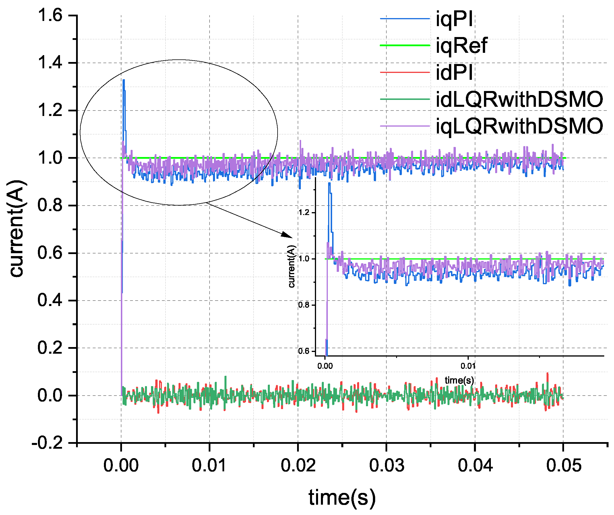
PI control can usually achieve good results and high reliability, and is easy to use, so it is widely used in practical engineering. This paper conducted comparative experiments with the classical PI controller to verify the LQR control effect of the designed disturbance sliding mode observer. The parameter selection of the PI controller is aggressive, with the Kp parameter set to 2.0 and the Ki parameter set to 2000.0. The simulation experiment results are as follows:
Setting the
q-axis command current of the current loop (iqRef in
Figure 2) to 1.0 ampere and the
d-axis command current to 0.0 ampere, the current tracking effect of the PI controller and the LQR based on DSMO are compared. The step response simulation test results are shown in
Figure 2 and
Figure 3.
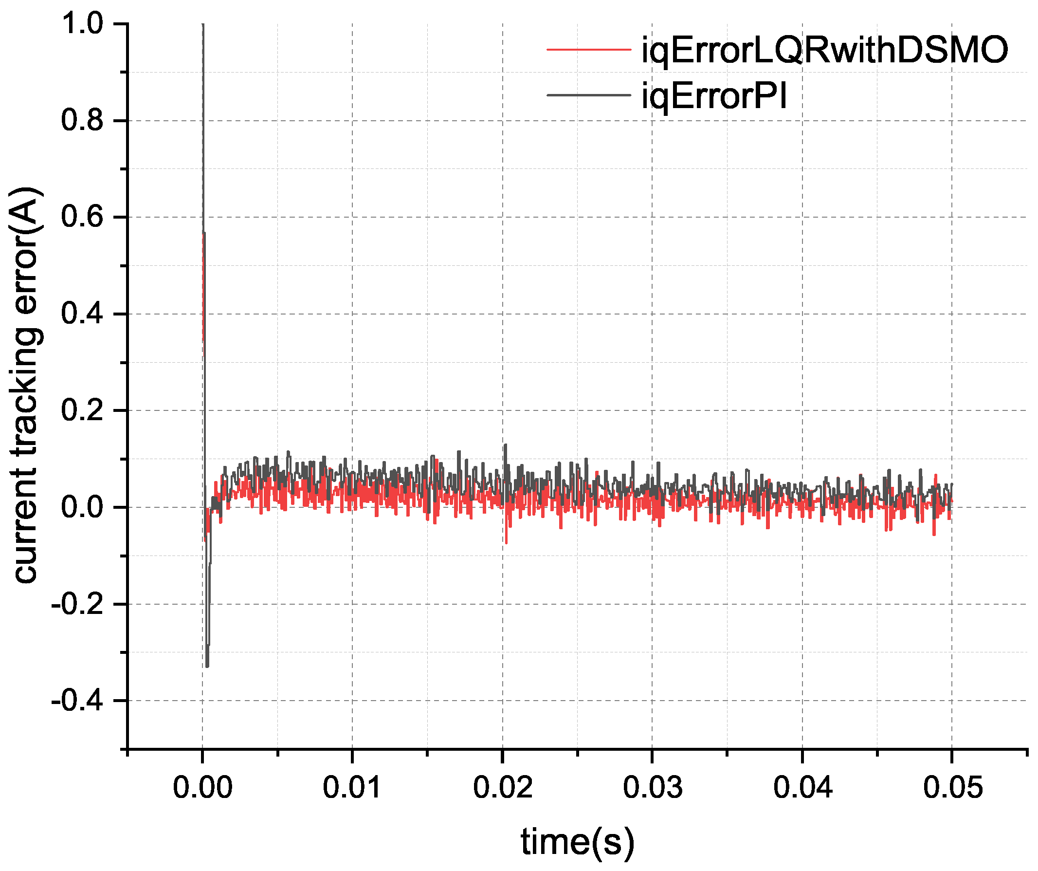
From
Figure 2 and
Figure 3, it can be seen that when the current command suddenly changes, the current of both schemes can quickly rise to the reference value of the command, indicating that the Kp parameter setting of the PI controller is relatively aggressive. However, there is a significant control error in the subsequent PI control, which gradually stabilizes at the reference value over time. Although there is some tracking deviation with the LQR control scheme based on DSMO, it maintains a good control effect. Based on the theoretical analysis in the
Section 2, it can be seen that the disturbance generated during the operation of the motor current loop is the reason for the control error. Although the integral effect in the PI controller has the ability to resist disturbances, the simulated Ki parameter set here is 2000.0, which is obviously more aggressive and can lead to instability in actual hardware motor control. However, it still cannot effectively suppress disturbances in the circuit. Compared to this, the disturbance feedforward scheme based on a sliding mode observer proposed in this paper shows better control performance.
Figure 3 is a comparison of the current tracking error results between the scheme proposed by this paper and the classic PI scheme.
By calculating the root mean square error (RMSE) of the current, the RMSE of the classical PI controller is 0.0695 A, and the root mean square error of the LQR current control based on a disturbance sliding mode observer is 0.0489 A, resulting in an improvement in the control accuracy of approximately 29.64%. Clearly, the control scheme proposed in this paper has achieved the expected results.
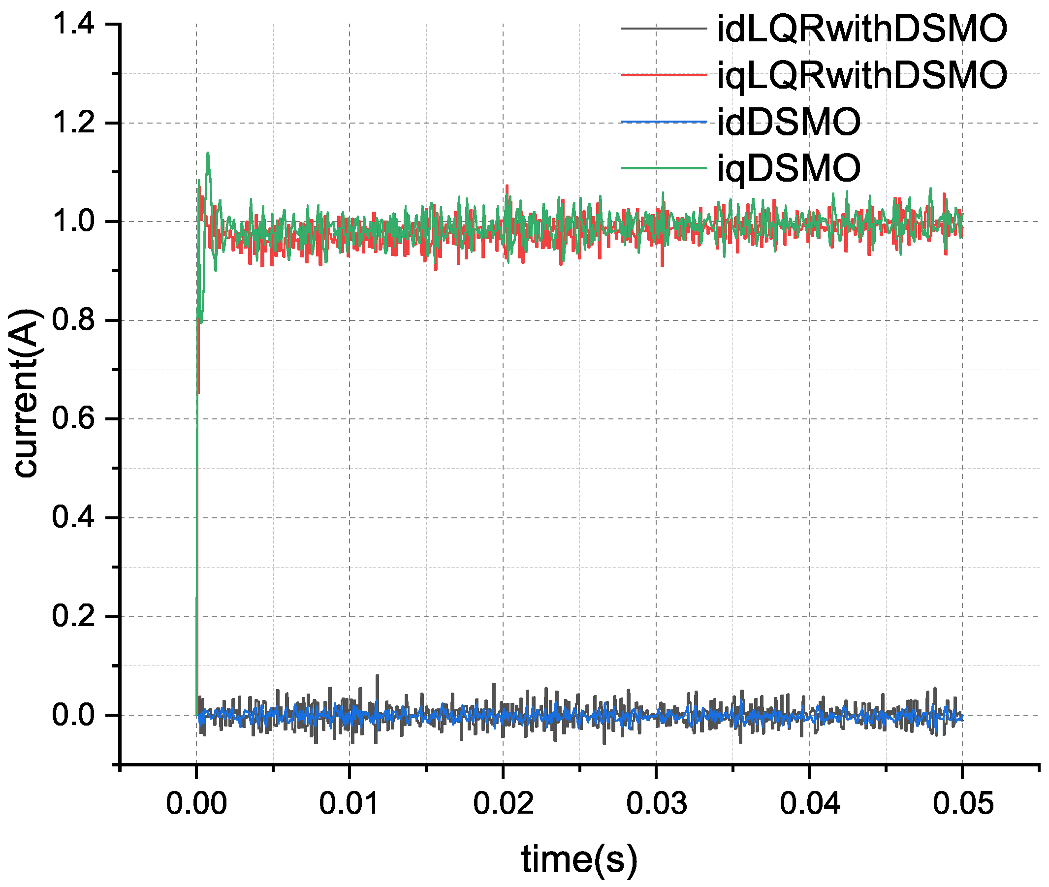
The current tracking effect of the disturbance sliding mode observer is a very intuitive criterion for evaluating the convergence of the observer. The results of the current value estimated by a sliding mode observer and the actual current value are shown in
Figure 4.
In
Figure 4, the red line represents the actual
q-axis current value, and the green line represents the
q-axis current value of the sliding mode observer. It can be seen that the sliding mode observer can quickly converge to the tracked
q-axis current, and the same is true for the
d-axis. This also verifies the correctness of the convergence analysis of the observer in the
Section 3.
The estimation of disturbances in the circuit by the sliding mode observer is shown in
Figure 5.
Under simulation conditions, the back electromotive force term in the circuit can be accurately obtained, as shown in the black curve in the figure. According to the theoretical analysis of the disturbance model Equation (
8), it can be seen that this is a larger part of the
q-axis disturbance. From the simulation results, it can also be seen that the variation trend of the
q-axis disturbance (blue curve) is the same as its main part of the back electromotive force, indicating the effectiveness of the disturbance estimator design.
In order to further verify the performance of the designed control scheme, current loop sweep frequency experiments were conducted under simulation conditions compared with the classical PI controller. The reference value of the current loop adopts a chirp signal with an amplitude of 1.0 A, and the frequency rises from 100 Hz to 1000 Hz within 0.05 s. The result is shown in
Figure 6.
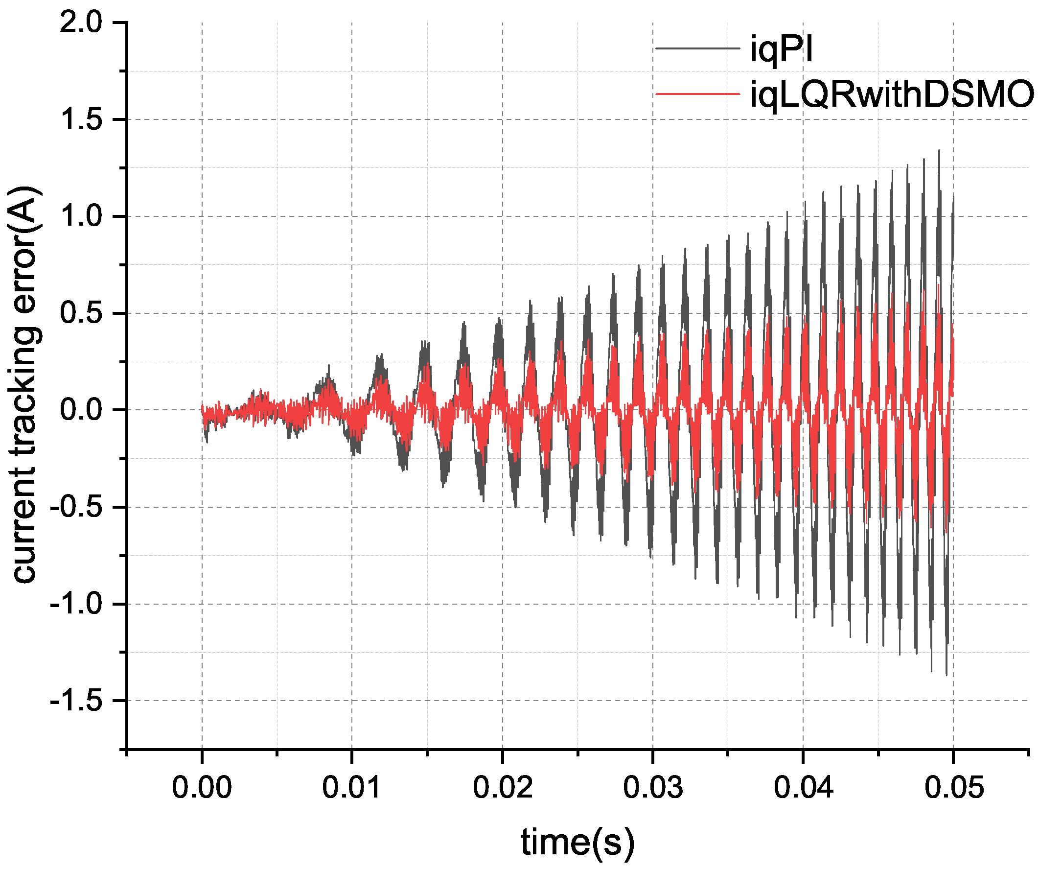
The comparison results of the current tracking error are shown in
Figure 7. From
Figure 7, it can be seen that as the frequency of current changes increases, the tracking error of the classic PI controller significantly increases, with a current tracking RMSE of 0.4289. The current tracking RMSE of the control scheme proposed in this paper is 0.1569, which improves the performance by about 63.41%.
The current tracking variation near the frequency sweep signal of about 1000 Hz is shown in
Figure 8.
In
Figure 8, the green curve represents the reference value of the
q-axis current, the blue curve represents the current tracking result of the control scheme proposed in this paper, and the red curve represents the current tracking result of the classical PI controller. In comparison, the classical PI controller shows a significant phase lag and tracking error.
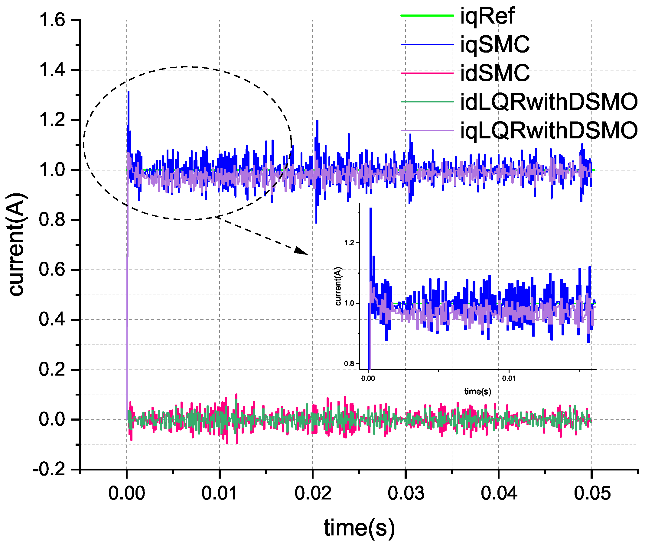
The primary objective of the disturbance observer proposed in this paper is to suppress disturbances within the control loop, which aligns with the goal of direct sliding mode control. To further validate the performance of the method introduced in this paper, a comparative analysis was conducted with an improved sliding mode control scheme. The improved sliding mode control strategy employs a saturation function in lieu of the signum function to mitigate the chattering phenomenon typically associated with traditional sliding mode control, which is a commonly adopted approach. The comparative results between the method proposed in this paper and the improved sliding mode control scheme, as demonstrated through computer simulations, are illustrated in
Figure 9.
The step response current tracking RMSE for the proposed scheme, the improved sliding mode control scheme, and the classical PI control scheme are presented in
Table 3.
From the rise phase of the current in
Figure 9, it can be observed that the current under sliding mode control can rapidly reach the reference current and fluctuate around it, indicating that sliding mode control possesses a strong disturbance rejection capability. However, the dynamic error of these fluctuations also becomes significantly larger. As shown in
Table 3, the calculation results of the RMSE for current tracking demonstrate that the performance of the improved sliding mode control in tracking current is superior to that of the PI controller in terms of root mean square error, but it is not as effective as the method proposed in this paper. This is attributed to the fact that the disturbance rejection and rapid response of sliding mode control are achieved by swiftly changing the direction of the control effort, thereby forcing the system state to oscillate around the sliding surface. Consequently, despite modifications to the switching function in the sliding mode control, the inherent chattering phenomenon remains challenging to eliminate. The comparison of control efforts during the current tracking process is depicted in
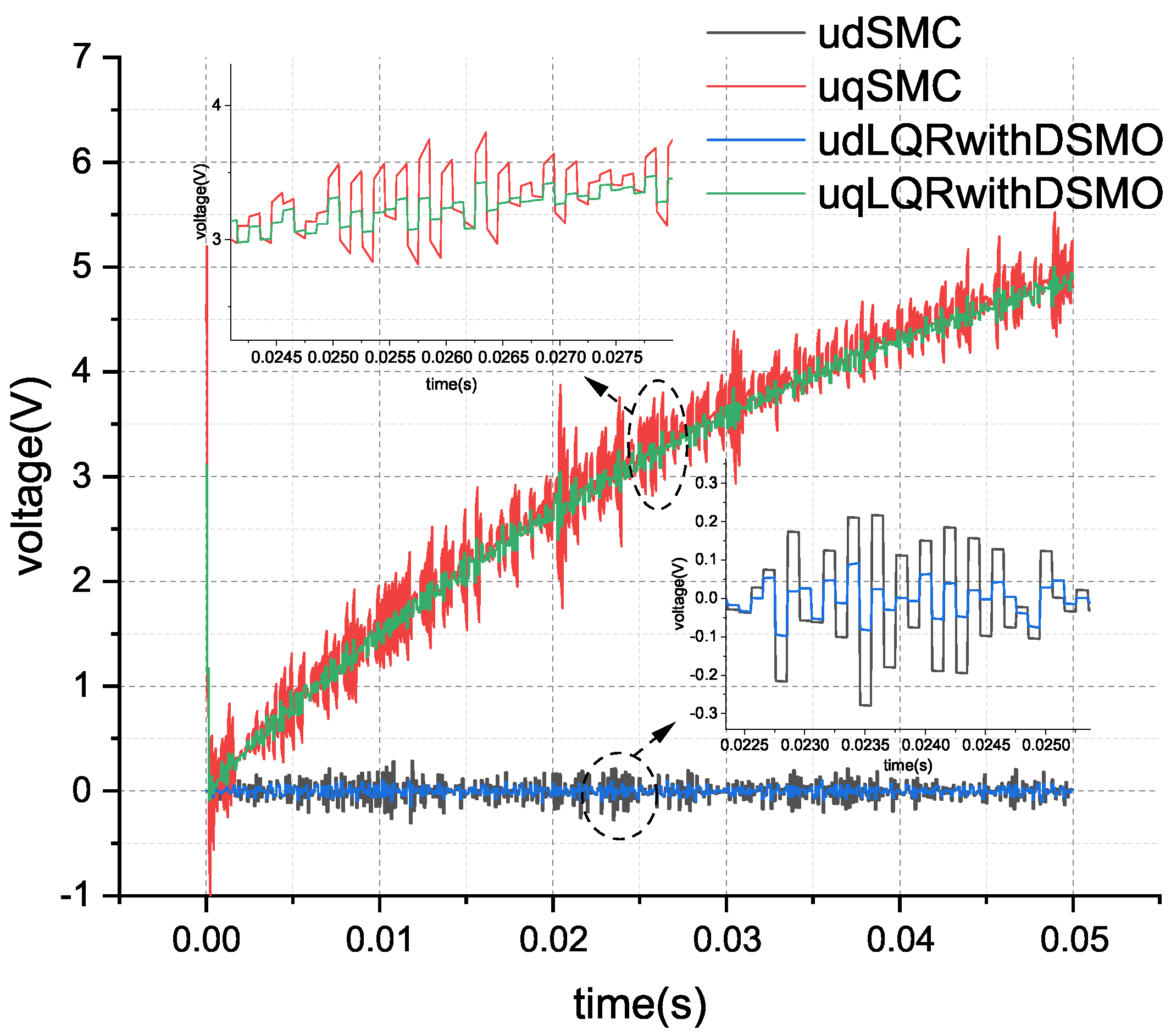
Figure 10.
The simulation results depicted in
Figure 10 reveal that the red curve, labeled ’uqSMC’, represents the control effort of the improved sliding mode control for the
q-axis voltage, while the green curve, marked ‘uqLQRwithDSMO’, corresponds to the control effort of the method proposed in this paper. It is evident that, in order to suppress disturbances, the sliding mode control exhibits a larger fluctuation in its control effort, which can induce vibrations throughout the system and potentially reduce the service life of the mechanical structure.
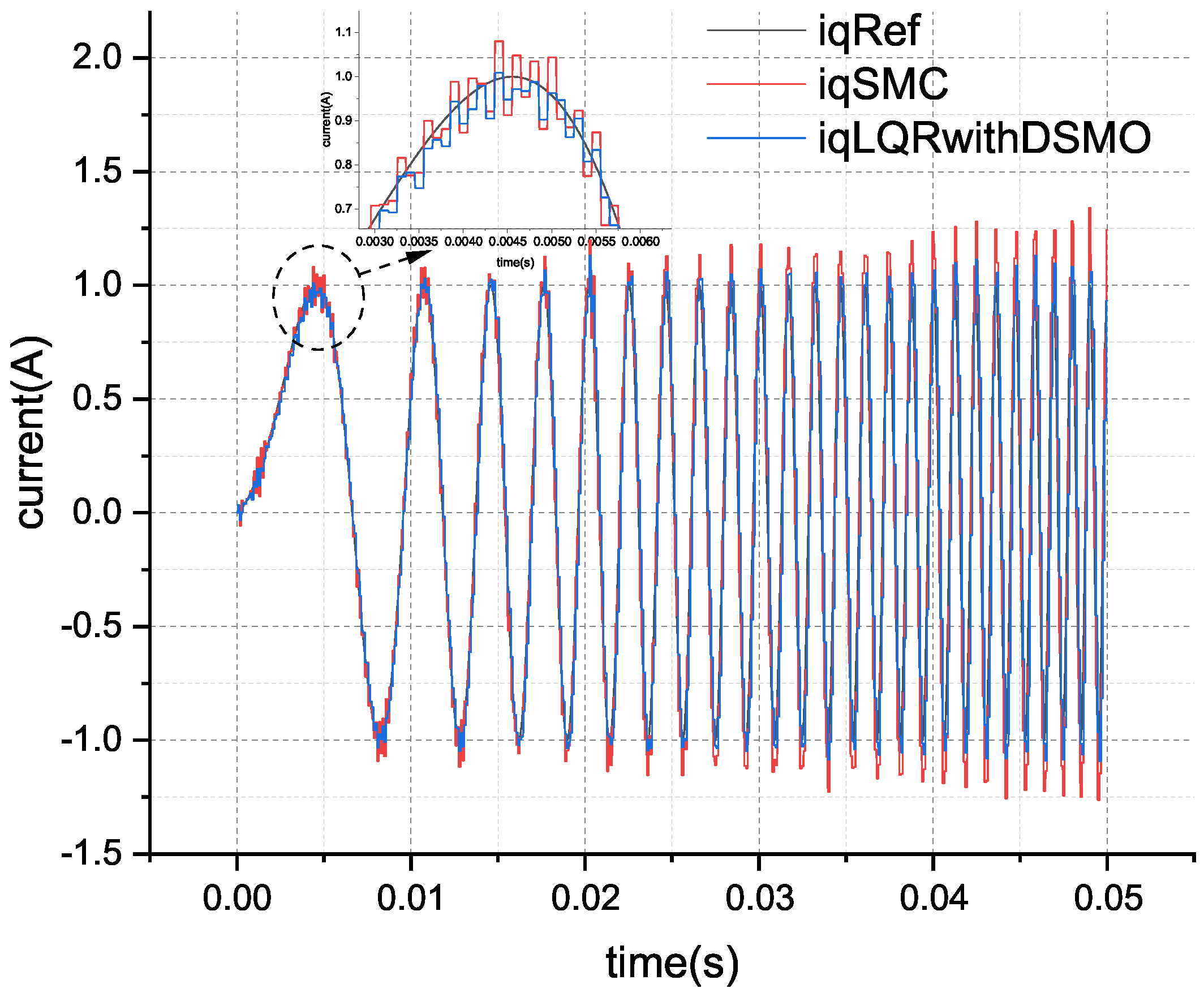
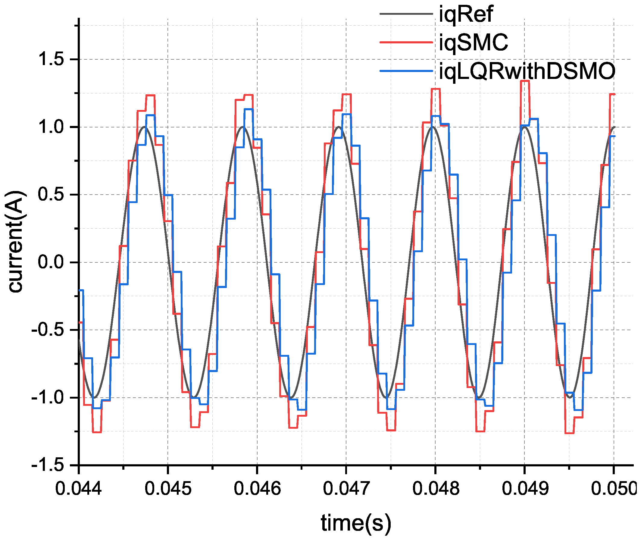
The sweep frequency simulation results for the current loop are illustrated in
Figure 11 and
Figure 12. The sweep frequency current tracking RMSE of the three control schemes is presented in
Table 4.
From
Figure 11 and
Figure 12, it can be observed that the tracking current under sliding mode control fluctuates rapidly around the reference current, yet with considerable error, as indicated in
Table 4, which is still indicative of chattering. It is evident that to achieve good disturbance rejection performance, even with improved sliding mode control, the inherent chattering phenomenon is difficult to eliminate. In contrast, the control method proposed in this paper does not have the aforementioned issues while resisting disturbance.
5.3. Experiment Protocol
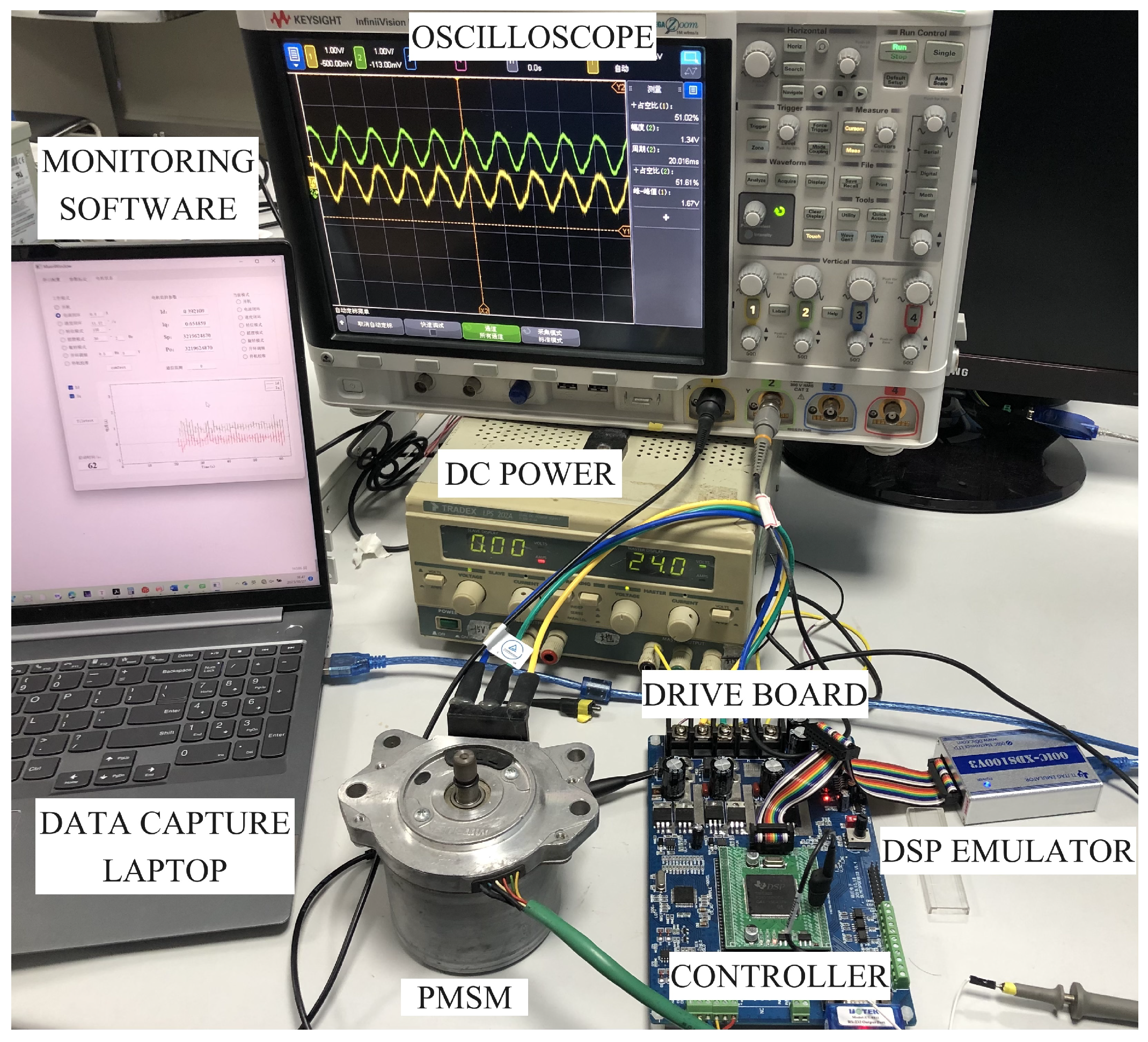
Validation experiments are conducted to compare the classical PI control method used widely in engineering with the current loop control scheme proposed in this paper. The hardware experimental environment used is shown in
Figure 13.
The PMSM tested in the validation experiment is the MITSUBA-PA66-GF30, and the real-time controller 32-bit floating point DSP (TMS320F28335, manufactured by Texas Instruments in Dallas, TX, USA) is used, which can run at 150 MHz system frequency, in order to process the measurement information, the FOC control algorithm, the PI control law, the proposed disturbance observer, and the output SVPWM waveform driving power board.
Two current Hall sensors (ACS758LCB-050B, manufactured by Allegro MicroSystems in Manchester, NH, USA) are used to measure the phase current of the PMSM, which are converted into a digital signal through the 12 bit ADC of DSP. The current of the third phase is calculated using Kirchhoff’s current law for the conversion from a stator -axis to a -axis synchronous coordinate system. A resolver scheme is adopted to measure the shaft rotation by the angle signal acquisition chip (AD2S1205, manufactured by Analog Devices in Norwood, MA, USA), which can achieve 12-bit resolution digital conversion. Six metal oxide semiconductor field effect transistors (HY3610, manufactured by Hooyi Semiconductor, Xi’an, China) are used to construct the motor-driven circuit board in the form of three half-bridge circuits, achieving three-phase command voltage through an inverter supplied by DC 24 V power to drive the PMSM.
The nominal parameters of the PMSM used to validate the proposed observer scheme are given in
Table 5.
5.4. Experiment Results and Discussion
After setting the current loop
q-axis command to 1.0 A and the
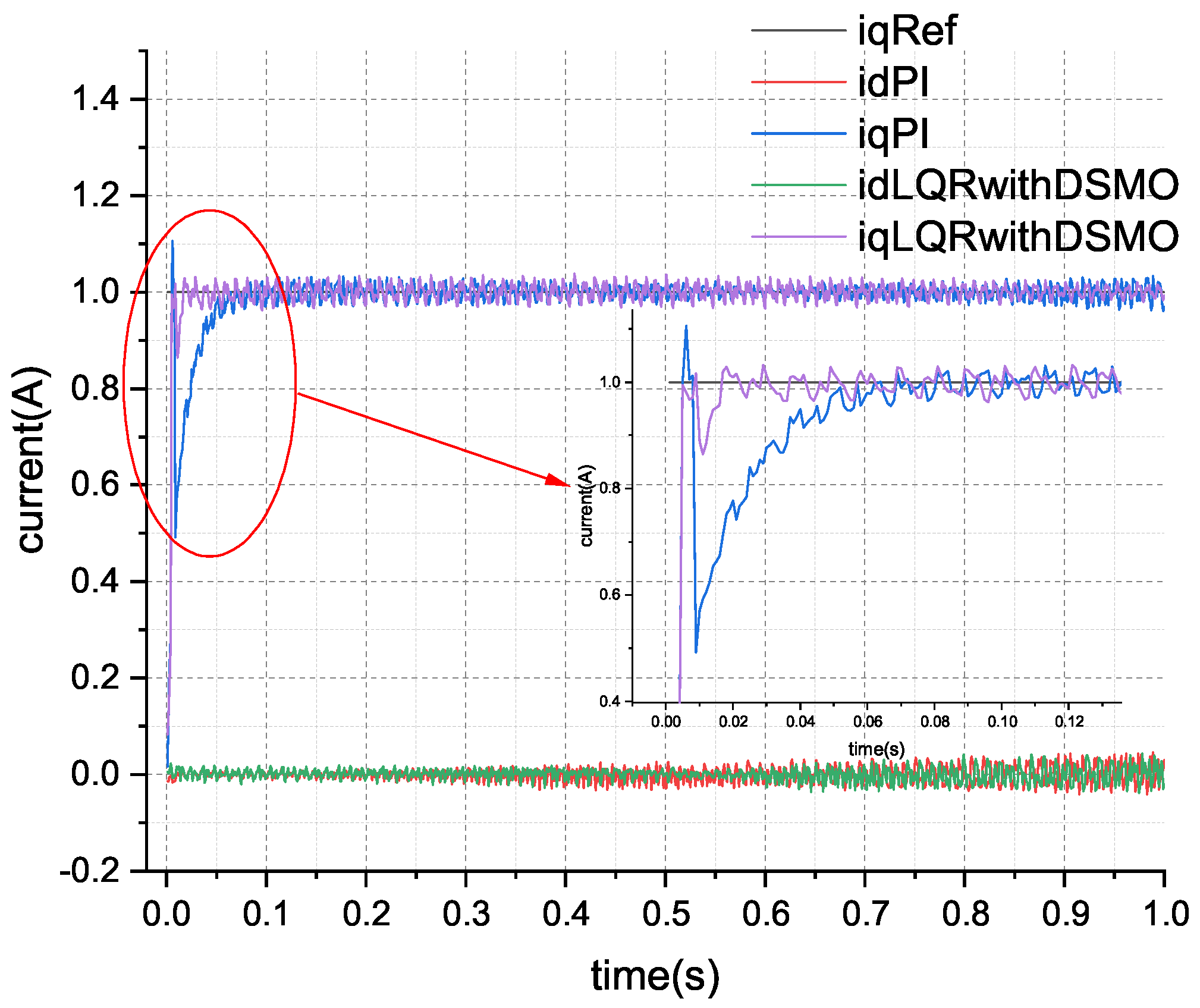
d-axis command to 0.0 A, and starting the current loop control circuit, the comparison results obtained between the proposed control scheme and the classical PI controller current response are shown in
Figure 14.
From the actual comparison results of current tracking, it can be seen that the current of the classic PI controller cannot stabilize at the reference value after rapidly rising above it. This is due to the internal disturbance generated by the circuit after operation, and the control error gradually decreases under the effect of integration. Compared to other methods, the LQR control scheme based on DSMO has a good anti-interference effect and can quickly and stably track the current reference value. The current tracking RMSE of classical PI control is 0.0716 A, while the current tracking RMSE of the LQR scheme based on DSMO is 0.0560 A, resulting in a 21.79% improvement in control performance.
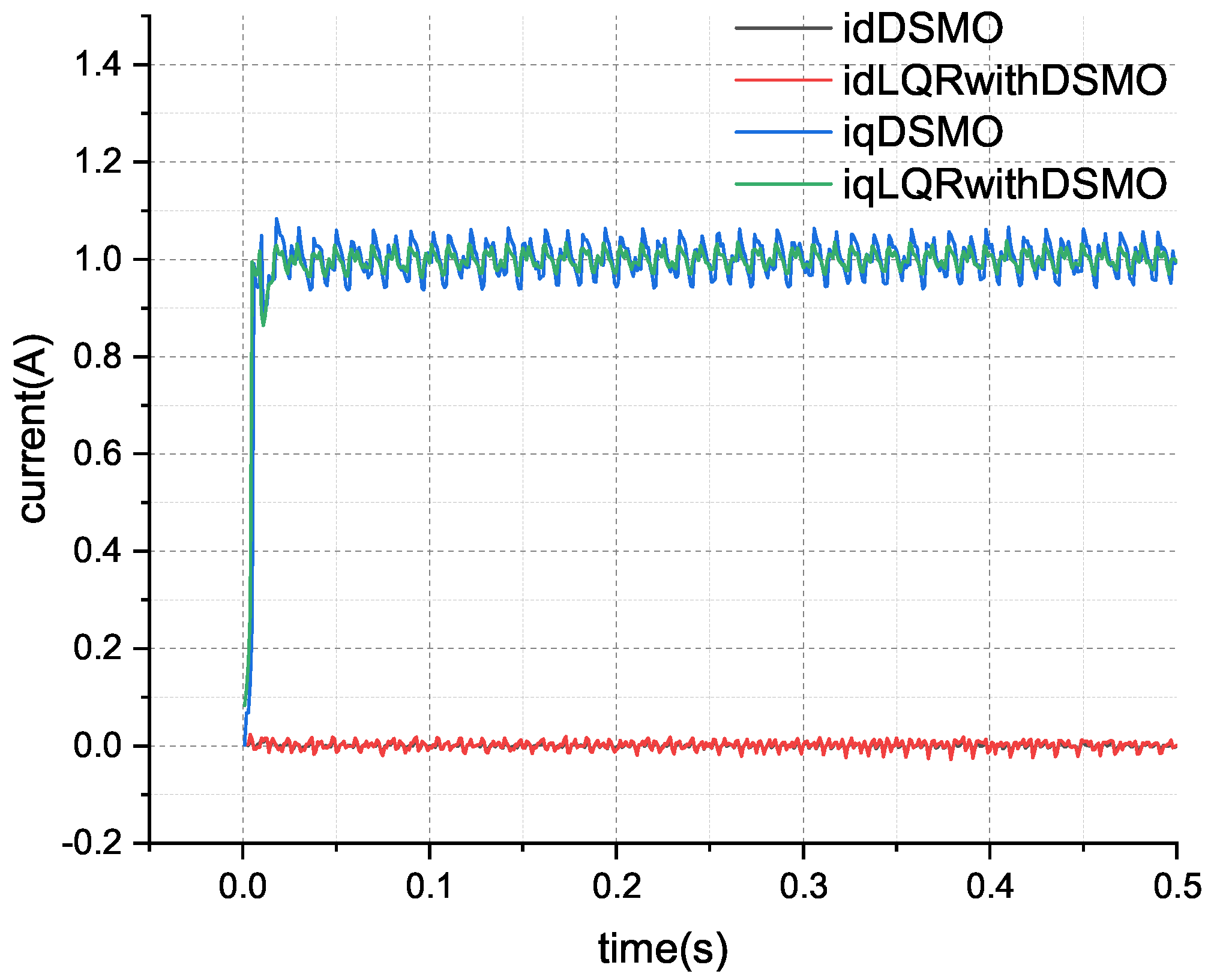
The current state convergence results of DSMO are shown in
Figure 15. From
Figure 15, it can be seen that DSMO can quickly and accurately track the changes in actual current, indicating that the observer has achieved fast convergence. The estimation of disturbances in the
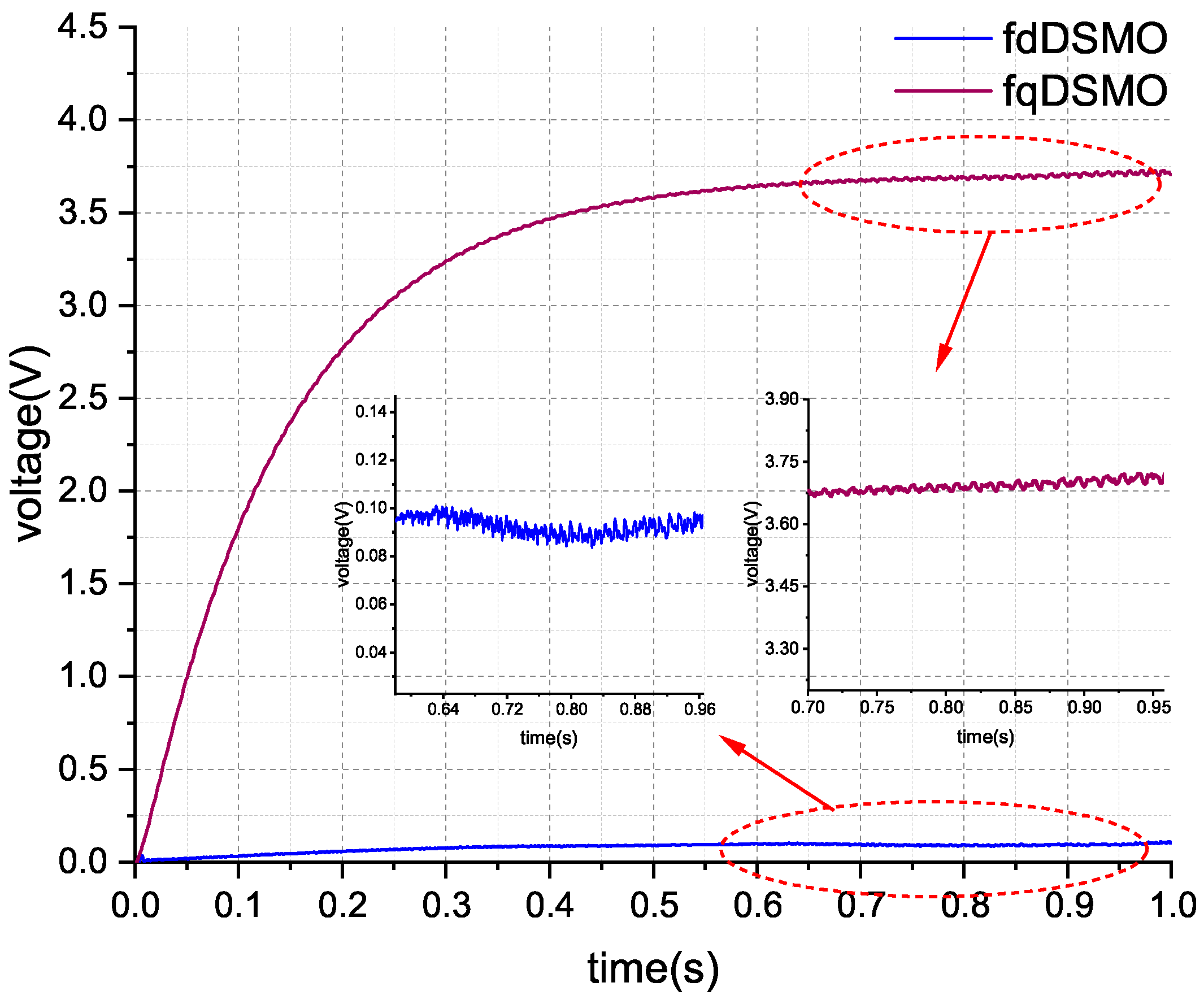
-axis by the sliding mode observer is shown in
Figure 16.
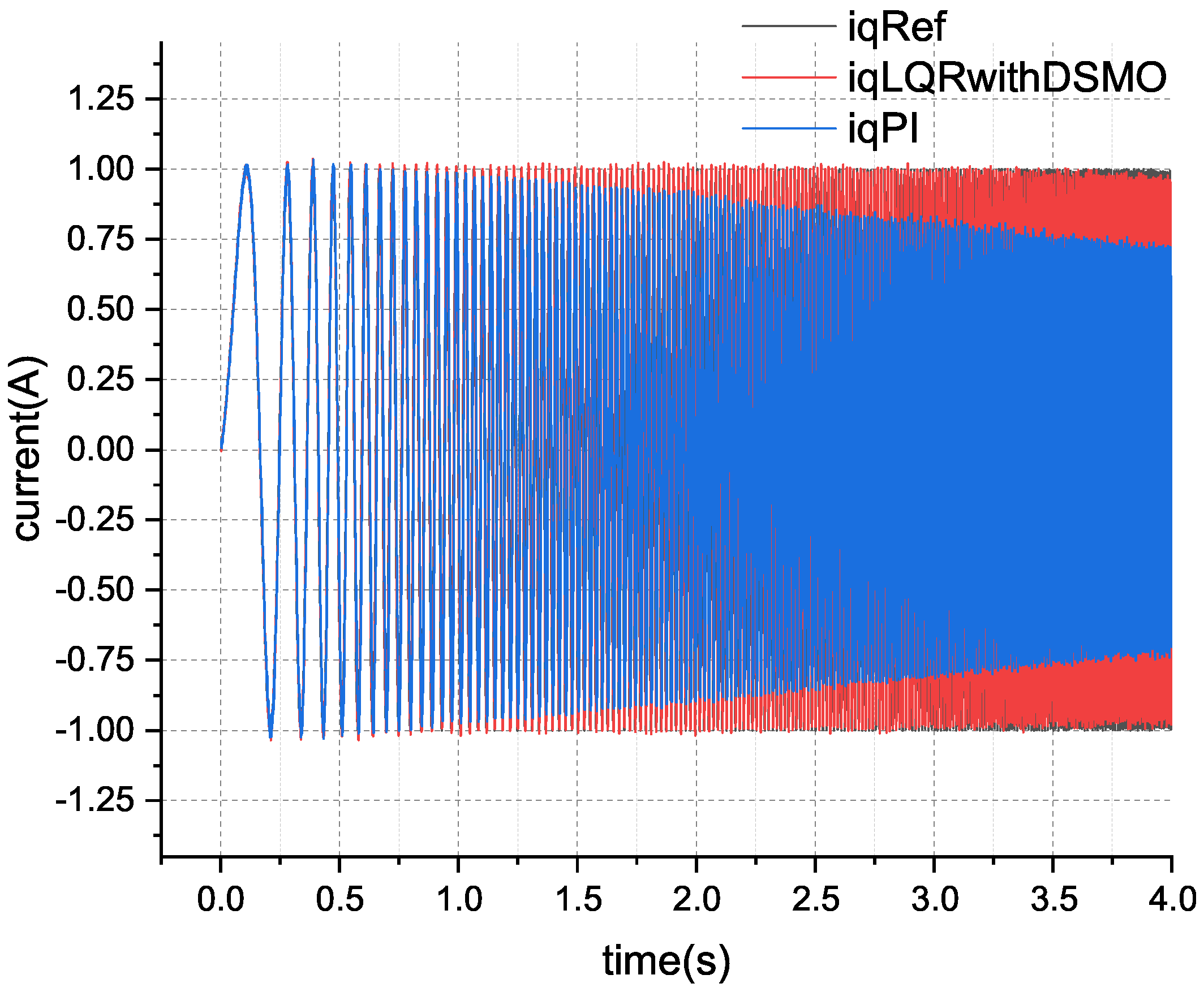
In order to fully verify the performance of the proposed control scheme, a sweep frequency test with an amplitude of 1.0 A and frequency change from 1.0 Hz to 101.0 Hz was conducted in actual PMSM current loop testing experiments, with a frequency increase time of 4.0 s. The results are shown in
Figure 17.
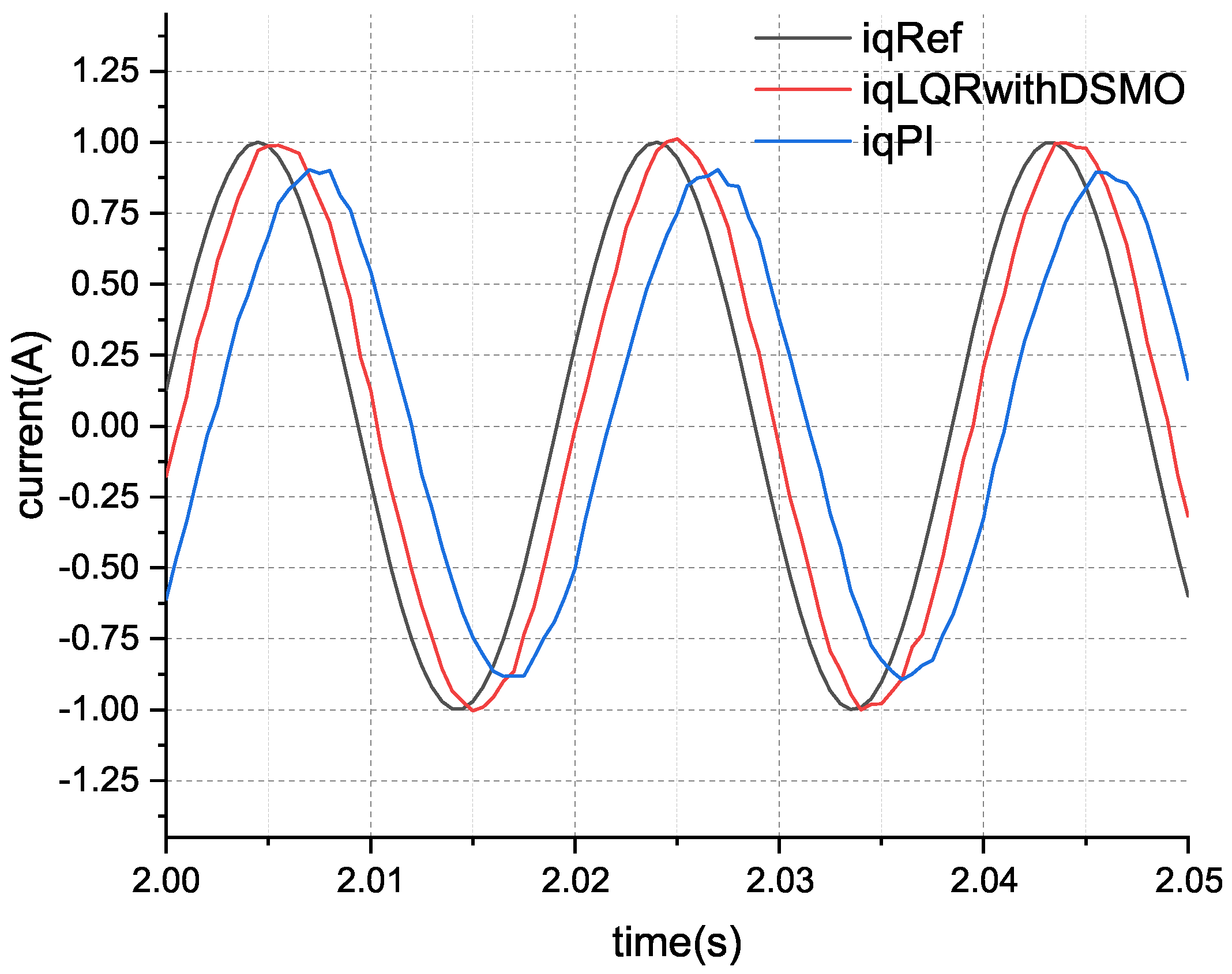
An enlarged diagram of the current tracking during the frequency sweep test is shown in
Figure 18. A comparison of current tracking errors in the frequency sweep test of the two schemes is shown in
Figure 19.
From the comparison results in
Figure 17 and
Figure 18 tests, it can be seen that classical PI control can track the current changes well in the low-frequency range. When the current changes quickly, the tracking effect of LQR control based on DSMO is significantly better than that of classical PI control. From the current amplification diagram during the frequency sweep process, it can be seen that for the current command curve (black curve, iqRef), there is a significant phase delay and tracking error in the classical PI control (blue curve, iqPI) compared to the DSMO-based LQR (red curve, iqLQRwithDSMO). After calculation, the current tracking RMSE of the classical PI control is 0.5621 A, while the current tracking RMSE of the proposed control scheme is 0.2582 A. Under the frequency sweep test conditions, the control accuracy was improved by about 54.07% using the scheme proposed in this paper.
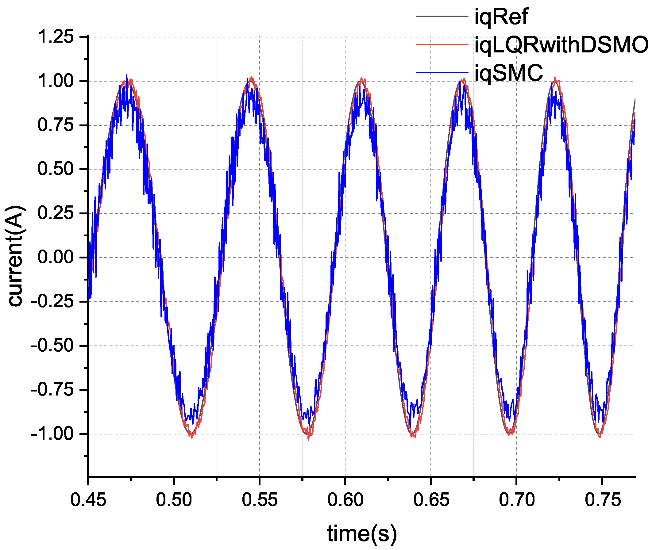
The comparative experimental results between the method proposed in this paper and the improved SMC scheme are shown in
Figure 20. The step response current tracking RMSE for the three control schemes is depicted in
Table 6.
The hardware expriment results in
Figure 20 indicate that the tracking current of the improved sliding mode control exhibits significant fluctuations around the reference value, and the chattering phenomenon is difficult to completely eliminate. The RMSE calculation results for current tracking in
Table 6 show that the tracking performance of the improved sliding mode control is superior to that of the classical PI controller, but it is not as effective as the method proposed in this paper, which is in basic agreement with the simulation results and discussion conclusions. The actual control efforts during the experimental process are compared as shown in
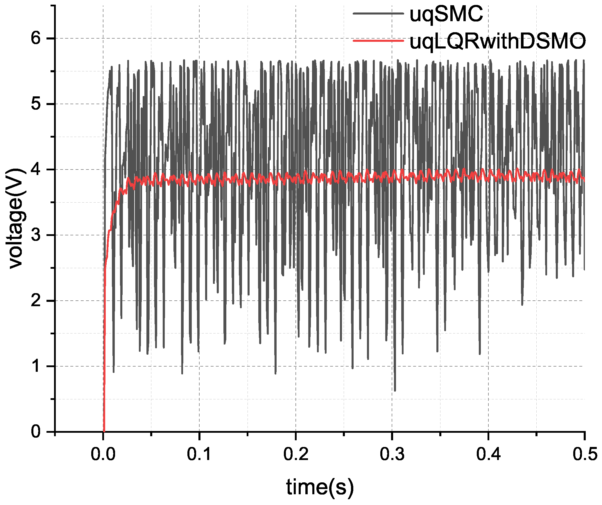
Figure 21.
The experimental validation results depicted in
Figure 21 reveal that the black curve labeled ’uqSMC’ corresponds to the control effort of the
q-axis voltage in the improved sliding mode control, while the red curve marked ‘uqLQRwithDSMO’ represents the actual control effort of the method proposed in this paper. It is evident that, in order to suppress disturbances, the control effort in sliding mode control fluctuates significantly, which may induce vibrations throughout the system and potentially reduce the service life of the mechanical structure. This finding is consistent with the conclusions drawn from the simulation analysis.
The comparative experimental results of the sweep frequency test for the current loop are illustrated in the subsequent
Figure 22 and
Figure 23. The RMSE of the sweep frequency experimental current tracking for the three control schemes is presented in
Table 7.
From
Figure 22 and
Figure 23, it is observed that the actual current under sliding mode control fluctuates rapidly around the reference current, albeit with a significant error, as demonstrated in
Table 7, which is indicative of persistent chattering. To achieve robust disturbance rejection, the improved sliding mode control still struggles to eliminate its inherent chattering issues. In contrast, the control method proposed in this paper effectively resists disturbance without the chattering problem. The actual experimental validation results and analytical conclusions are fundamentally consistent with the simulation findings.

