Abstract
In this paper, we propose the design, development, and testing of high-torque and lightweight actuators suitable for lightweight robotic applications. The detailed design of the actuator module is described, and its performance evaluation is also presented. Further, the mathematical modelling of the actuator is discussed. Various performance analysis tests were carried out for the elucidation of the designed actuator, which included primarily position, velocity, and torque analyses. The position accuracy analysis included position repeatability at the maximum payload for calculating the acceptable tolerance. The velocity elucidation included a velocity test for the variable load. The torque analysis of the actuator was completed at different supply currents. These tests and the results indicate that the proposed actuator has high precision in reaching the desired position and provides a stabilized performance with variable loads up to the limit for which it was designed. Based on the torque output and the weight, the proposed actuator could be a good fit for lightweight robotic applications.
1. Introduction
Robotic technology has become ubiquitous, spanning across various fields such as agriculture [1], search and rescue [2], surgery [3], rehabilitation [4], service [5], healthcare [6], and underwater operations [7]. In recent years, the interaction between humans and robots has surged significantly. It is imperative for human operators to exercise the utmost caution when working alongside robots. In industrial settings where robots are utilized, there is the potential for humans to operate robots beyond a safe operating range. When human operators need to collaborate closely with robots, several crucial parameters, apart from safety, must be taken into consideration. The global market for collaborative robots is projected to undergo substantial growth, with anticipated revenues soaring from USD 981 million in 2020 to an estimated USD 7172 billion by 2026. This surge reflects a remarkable uptick, with the market steadily expanding at an average annual growth rate of approximately 41.2% [8,9]. Factors such as weight, operating power, response time, and accuracy play pivotal roles in designing robot systems intended for close human interaction. Among these considerations, the actuator stands out as a crucial component that significantly influences the weight of such a system [10].
Actuators are integral components in numerous robotic applications, valued for their exceptional precision and accuracy. While there are many high-performance actuators available, their size and weight pose challenges, rendering them less suitable for lightweight robotic applications, especially in collaborative settings. Consequently, the endeavor to develop high-performance actuator modules tailored for lightweight robotics remains a formidable challenge, owing to these constraints. Several researchers have dedicated efforts to enhance various aspects of actuators. Mohammad Salah et al. [11] introduced a backstepping control algorithm coupled with a robust scheme. Their focus was on applying this algorithm to the four-bar linkage mechanism to investigate its dynamic performance across diverse operating conditions, without prior knowledge of the model’s parameters. Their objective was to design a nonlinear controller capable of addressing the intricate behavior associated with the nonlinear dynamics of the four-bar linkage mechanism. However, it is important to note that the algorithm’s validation was confined to simulations and has yet to be tested in real-time scenarios. Similarly, Nan Li et al. [12] proposed a control algorithm for the IMU-based active and safe control of a variable stiffness soft actuator. They asserted that their active and safe control algorithm offered distinct advantages over the passive compliance reaction of a typical soft robot. However, their model had notable limitations. Load estimation at any given position was not achieved, and the proposed model lacked precision due to the omission of dynamic influences and excessive simplifications. These limitations warrant further investigation and refinement of their proposed model.
Yongping Pan et al. [13] introduced a linear proportional–integral–derivative (PID) controller that was theoretically suitable for the tracking control of robotic manipulators powered by compliant actuators. They formulated the control problem into a three-time-scale singular perturbation formula, encompassing a slow time-scale at the rigid robot dynamics, an actual fast time-scale at the actuator dynamics, and a virtual fast time-scale at the controller dynamics. However, their design was applicable only when the spring stiffness exceeded the other parameters of the robot dynamics. Moreover, the tracking accuracy of their PID controller was limited by control gains and spring stiffness, which were attributed to the practical exponential stability. In another study, Julie Legrand et al. [14] presented an integrated capacitance sensor for miniature artificial muscle actuators by replacing two strands of the muscle braid with two conductive wires. This innovation resulted in a miniature muscle actuator with integrated capacitance sensing, maintaining 97% of its contraction length compared to an original McKibben muscle. However, this method introduced a potential error of approximately 8% on the total muscle length range due to loading. Additionally, the muscle with an integrated sensor has not yet undergone testing in closed-loop systems under various environments, and further investigation is needed to study the effect on capacitance measurement.
Yuichi Tazaki [15] introduced a novel leg design for bipedal walking robots, utilizing a six-degrees-of-freedom (6-DOF) parallel link mechanism. This innovative design enabled the integration of all leg actuators within the torso, resulting in a significant reduction in leg inertia. However, it is worth noting that parallel link mechanisms inherently have a limited movable range compared to serial links. In our earlier work [16], we proposed a linear load cell to measure the torque exerted on the shaft of a geared DC actuator controlled by a PID controller. We explored the potential of using minimal sensors to achieve multiple actions performed by the actuator. However, while this approach showed promise, the analysis of the error percentage remained incomplete, and further robust testing and validation were necessary to ensure its reliability and accuracy. In another study focusing on the mechanism of actuators, Gilad Refael et al. [17] explored a straightforward swimming mechanism consisting of two concentric bodies and two passive flaps. This mechanism achieved forward propulsion by symmetrically oscillating its inner body using a single actuator. However, a drawback of their proposed model was the oversight of the open and close times of the flaps, resulting in slow movement. In a related study, Tallapragada P. et al. [18] proposed a mechanism capable of the following two seemingly disparate modes of motion: one on land and the other in water, both governed by a nonholonomic constraint. However, this work lacked detailed information regarding the precise motion of the robot and its swimming efficiency, representing some of its limitations.
Researchers have devised various methods for measuring speed and position in actuators. Marko Nerat et al. [19] introduced a novel fast-filtering method for rotational speed measurements, specifically designed for brushless direct current (BLDC) motor drives. However, it is worth noting that their proposed fast-filtering algorithm operated under the assumption that speed jitter is periodic, which may not always hold true in real-world scenarios. In another study by R. K. Megalingam et al. [20], a Simulink-based model was developed to construct a controller driver system for regulating the position and speed of a BLDC motor using semiconductor switching devices and digital sequential blocks. The model’s validity was confirmed through a prototype setup involving a BLDC motor. Nevertheless, there remained room for improvement regarding the accuracy in this work, and the implementation of error detection and correction measures has not yet been addressed.
In the realm of torque ripple reduction in actuators, Jonathan Terfurth et al. [21] introduced a prototype of a planar-aligned transverse flux machine with spatially distributed phases. This innovative topology allowed for a flatter assembly space compared to conventional transverse flux machines and incorporated a reduction gear. The resulting machine exhibited a low relative torque ripple, making it well-suited for the low-speed, high-torque applications commonly encountered in medical or industrial robotic environments. However, their proposed method did not address efficiency considerations in planar designs, leaving room for further enhancements in efficiency. In a similar study, Besir Celebi et al. [22] presented the ASSISTON-KNEE, a novel self-aligning active exoskeleton for robot-assisted knee rehabilitation. Their approach to improving torque performance involved mechanically low-pass filtering torque ripples using spring elements before application. However, the efficiency of this method was relatively low compared to a previous study [21], indicating potential areas for optimization and efficiency improvement. Tarek Kendjouh et al. [23] focused on enhancing the performance of a toothed-pole variable reluctance machine which was excited by permanent magnets housed in its stator yoke. The primary goal of their research was to mitigate the electromagnetic torque ripples stemming from the structural geometry and supply techniques. By addressing these issues, the efficiency of the machine could be enhanced through a reduction in joule losses. This work represented a significant effort in optimizing the performance of variable reluctance machines, with potential applications in various industrial and automotive settings where torque ripple reduction and energy efficiency are critical considerations.
Akash Varshney et al. [24] noted that gradually applying load to a motor yields superior performance compared to a sudden application. Torque control methods are also applicable in vehicular technology. Researchers have also been directing their efforts towards reducing actuator sizes and altering their shapes. In the research conducted by Lisa Schmit et al. [25], non-inchworm cooperative micro-electrostatic actuators with long-stroke, stepwise displacements were investigated. Aditya K. et al. [26] discussed the effective applications of micro-actuators. Tobias Taufer et al. [27] delved into the utilization of brushless MM122 technology to develop uniquely flat actuators. Over time, researchers have primarily focused on designing high-performance actuators while adhering to constraints such as compact size, light weight, low power consumption, and rapid response time.
The primary contributions of this research work include the following:
- (a)
- The design and fabrication of a lightweight, high-torque actuator with improved performance while minimizing mass.
- (b)
- Kinematic error modeling as the research delved into modeling the kinematic errors associated with the proposed actuator. Understanding and quantifying these errors was crucial for optimizing the performance and accuracy of the actuator in practical applications.
- (c)
- The design and fabrication of a test setup, as a dedicated test setup was designed and fabricated to validate the functionality and performance of the proposed actuator. This setup provided a controlled environment for conducting the experiments and gathering empirical data to assess the actuator’s capabilities.
- (d)
- Performance evaluation and validation, as the research conducted comprehensive performance evaluations and validation tests on the fabricated actuator. Through rigorous testing and analysis, the team aimed to verify the effectiveness and reliability of the proposed model in real-world scenarios, ensuring its suitability for practical applications.
The rest of the paper is organized as follows: We commence with an overview of the system architecture of the actuator, detailing its key components and operational framework. Following this, we delve into the design of the actuator module using SolidWorks 10 and outline the fabrication process for its mechanical components. Subsequently, we present the mathematical modeling of the actuator, elucidating the theoretical underpinnings that govern its functionality and performance characteristics. Moving forward, we describe the experiments conducted to evaluate the actuator’s position repeatability, velocity under variable load conditions, and torque analysis for varying currents. The findings and results derived from these experiments are presented and discussed in the corresponding sections. Finally, we provide a comprehensive summary of our work and draw inferences from the outcomes, offering insights into the implications and potential avenues for future research in this domain.
2. Method
Developing actuators for lightweight robotic applications remains a formidable challenge, primarily due to constraints related to size and weight. In many applications, tasks necessitate greater precision, demanding actuators capable of delivering precise positioning and high torque outputs. The weights of components such as the BLDC motor, harmonic drive (Lead drive, China), and housing parts significantly impact the overall weight of the actuator module. To address this challenge, our proposed actuator incorporates various housing parts for the frameless BLDC motor, encoder, and harmonic drive, featuring hollow structures designed to reduce overall weight while maintaining strength. The design of the output flange serves as a connectivity conduit for the housing parts, wave generator, flex spline, and circular spline. This innovative mechanical alignment approach facilitates a weight reduction without compromising the structural integrity. In the subsequent subsections, we provide a detailed description of the mechanical alignment methodology, along with insights into the design considerations governing its control mechanisms.
2.1. System Architecture
The system architecture for the actuator is illustrated in Figure 1. The actuator comprises three main components: the core BLDC motor, harmonic drive, and hall-effect sensors. The controller receives signals from the hall-effect sensors and generates corresponding three-phase signals to drive the BLDC motor. The harmonic drive, integrated with the BLDC motor, multiplies the torque while reducing the motor’s speed. The PC communicates commands to the controller, with the EPOS4 controller chosen for this evaluation. The EPOS4 controller offers control modes for position, velocity, and current, with a built-in PID for optimal and rapid responses. The core BLDC motor utilized in this actuator is a Maxon BLDC motor, which is compatible with EPOS controllers. The encoder employed is an AksiM encoder, a contactless, off-axis absolute rotary encoder featuring 16 single-turn bits. It comprises an axially magnetized hollow ring and a read-head board. Renowned for its true absolute functionalities, hollow ring design, and high operation speed, the AksiM encoder stands out as a precision device suitable for a wide array of applications.
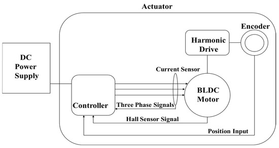
Figure 1.
Actuator system architecture.
2.2. Actuator Module
Figure 2 depicts an articulated view of the developed actuator CAD model, meticulously designed using SolidWorks. The actuator module encompasses key components such as the harmonic drive system, encoder, core motor, and various mechanical housing parts. Notably, the mechanical parts and harmonic drive system are intricately crafted to achieve a reduction in overall weight while simultaneously enhancing performance compared to existing actuators. The core principle of operation entails the amplification of input power generated by the core motor through the harmonic drive system, ultimately manifesting at the load side. Figure 3 provides a comprehensive overview of the various parts comprising the fabricated actuator module. The specifications of the harmonic drive are provided in Table 1.
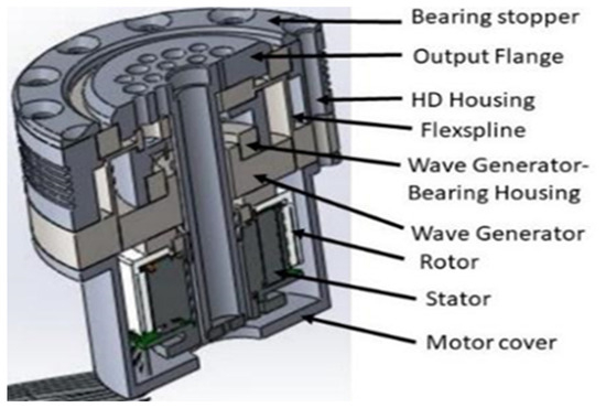
Figure 2.
CAD model of the actuator.
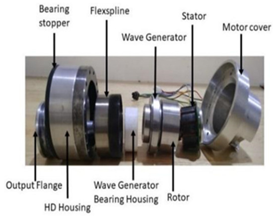
Figure 3.
Actuator parts.

Table 1.
Harmonic drive specifications.
The harmonic drive’s design incorporates a wave generator, circular spline, and flex spline, constituting a three-component system engineered to amplify input power, resulting in an impressive reduction ratio of 1:160 within a compact structure. The characteristics of this system, outlined in Table 1, include a high torque capability of 40 Nm, zero backlash, high position accuracy (1 Arcmin), high stiffness, and co-axial orientation of the input and output. The wave generator, comprising a race ball-bearing attached to an elliptical hub, serves as a high-torque converter, with the core motor shaft mounted to it. The flex spline, a thin cylindrical structure with external teeth at the open end of the cup, is affixed to the wave generator and functions as the output gear. The circular spline, featuring internal teeth and two additional teeth compared to the flex spline, remains constant and is fixed to the housing parts in our configuration.
The mechanical parts of the actuator encompass several components, including the output flange, harmonic drive (HD) housing, bearing stopper, wave generator bearing housing, rotor coupler, stator bearing connector, and motor cover. The design of the output flange, depicted in Figure 3, facilitates the mounting of the encoder at one end of the hollow shaft and features flange-holes for attaching various loads and internal housing parts. Similarly, the design of the HD housing and wave-generator bearing housing, as shown in Figure 3, aids in internally mounting the harmonic drive system. Lastly, the rotor coupler, stator bearing connector, and motor cover, also illustrated in Figure 3, were designed in conjunction with the output flange and HD housing to accommodate the core motor within the harmonic drive system.
2.3. Torque, Power, and Error Modeling
In this research, the core motor utilized for designing the actuator was specified as the Maxon Electronically Commutated (EC) brushless motor. The actuator’s modeling encompassed both electrical and mechanical characteristics. The electrical characteristics of the core motor can be derived by approximating it as a circuit consisting of an inductor, resistor, and back EMF. The resistor model corresponds to the resistance of the winding in the motor, while the back EMF represents the voltage generated by the movement of charged particles within the magnetic field. The inductor is depicted as the inductance generated by the winding in the motor. In our modeling approach, we aimed to derive the actuator transfer function by integrating the core motor transfer function with the harmonic drive parameters.
The electrical characteristics of the motor can be calculated as follows:
where represent the phase voltages; M represents the mutual inductance; L represents the inductance; represent the phase currents; and R represents the resistance of the coil. In employing Equation (1), we assumed that there was no change in the reluctance of the rotor. In addition, the damping factor was assumed to be small and could be neglected.
Therefore, the phase current of the motor can be calculated ( representing the back EMF voltages) in equational form as follows:
where represents the overall inductance of the coil. The mechanical characteristics can be determined using the torque generated, which is directly proportional to the amount of current passing through the core motor, as follows:
where T denotes the torque of the motor, denotes the proportional constant, and i denotes the current flowing through the motor.
The equation for simple torque along with the inertia, load torque, and coefficient of friction is as follows:
From Equations (5) and (6), we can determine the following:
From Equations (2) and (7), we can determine the following:
where represents the back emf constant, represents the angular velocity of the motor, J represents the rotor inertia, B represents the coefficient of friction, and represents the torque of the load. The friction is assumed to be small and neglected in order to arrive at Equation (9). The transfer function of the motor is represented in Equation (9), where the input is the voltage and output is the angular velocity of the motor.
The standard equation for the wave generator, flex spline, and circular spline used in the design of the harmonic drive is defined as follows:
where denotes the rotation of the wave generator, denotes the rotation of the circular spline, denotes the rotation of the flex spline, and N denotes the gear ratio of the harmonic drive.
In our case, the motor shaft was attached to the wave generator, the output was taken at the flex spline, and the circular spline was constant.
Therefore, we determined the following:
From Equation (10), we determined the following:
The angular velocity of the harmonic drive could be calculated by taking the differentiation of rotations of the wave generator.
From Equation (13), we determined the following:
where represents the angular velocity of the wave generator, represents the angular velocity of the circular spline, and represents the angular velocity of the flex spline.
The torque constraint of an ideal harmonic drive system is determined as follows:
where denotes the torque of the wave generator, denotes the torque of the circular spline, and denotes the torque of the flex spline.
A kinematic error is due to imperfections in tooth alignment, incorrect assembly, design error, mechanical machining, and misalignments between the principal axis of the driveshaft and the flex spline. The kinematic error of a position can be calculated as follows:
where represents the kinematic error of the position accuracy, represents the input position, N represents the gear ratio of the harmonic drive, and , theoretically, is the calculated position at output.
The mechanical reduction in the harmonic drive system can be derived as follows:
where represents the number of teeth in the flex spline, represents the number of teeth in the circular spline, and N denotes the gear ratio of the harmonic drive.
The final kinematic error equation can be written as follows:
where is the actual position at output.
The force, torque, and power relationship of the actuator module is as follows:
where ω represents the angular velocity, represents the power of the core motor, and T represents the total torque of the actuator module.
From Equation (9), the output velocity of the harmonic drive end can be calculated as follows:
From Equation (22), the torque and power relationship, the torque of the overall developed actuator module can be calculated as follows:
The speed of the actuator can be calculated using Equation (25), as follows:
where represents the speed of the actuator, represents the resonant frequency of the motor, represents the total number of poles, represents the load inertia, represents spring constant, and represents the gear ratio of the harmonic drive.
Figure 4 depicts the fully assembled developed actuator. The dimensions of the developed actuator were 70 mm × 75 mm, and it had a cylindrical structure with an overall weight of 788 g. The harmonic drive we developed was a CSF 20 series with a reduction ratio of 160.
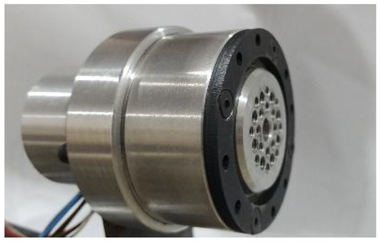
Figure 4.
The actuator fabricated as per the proposed design.
The mechanical housing parts were fabricated using 6000 series aluminum. Mild steel was also used to fabricate the rotor coupler and stator bearing connector. We developed an actuator module using a Maxon EC brushless motor (switzerland) as the core motor. The optimized magnetic circuit with iron winding resulted in a low cogging torque and high torque density. The Maxon EC brushless motor is a multipole motor with eight pole pairs, three-phase winding, a preloaded ball bearing, and a permanent magnet with NdFeB. Table 2 provides the specifications for the actuator that we designed and fabricated.

Table 2.
Actuator specifications.
3. Experiments and Results
The experimental setup shown in Figure 5 was designed in such a way that the actuator could be tested at different operational modes and orientations. The CAD model of the test setup is shown in Figure 6. The various components used to validate our actuator were a PC, a controller, a dial gauge, a DC power supply, standard weights, and an iron link. The iron link was attached to the actuator for placing the variable weights for testing. A power supply of 24 V was provided to the controller from the DC power supply. The controller could run the motor in the following three different modes: a position mode, a velocity mode, and a current mode. In the position mode, we tested the precision of the actuator; in the velocity mode, we measured the performance of the actuator at variable loads; and in the current mode, we evaluated the torque of the actuator.
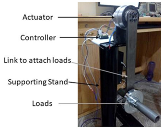
Figure 5.
Actuator test setup.
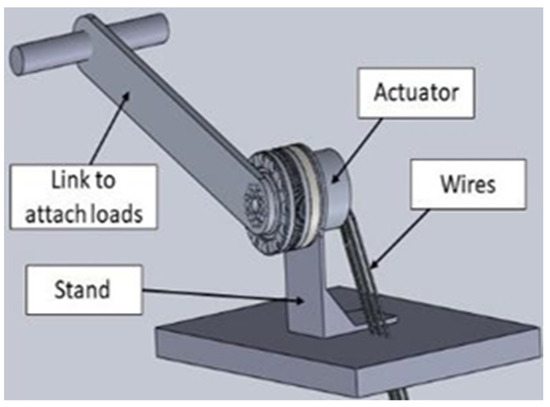
Figure 6.
Test setup of the CAD model.
3.1. Position Repeatability Test
The experimental setup for the position repeatability test is depicted in Figure 7. A dial gauge was used to calculate the error in the position. For calibration, the dial gauge was arranged in such a way that when the actuator was commanded to move, the link hit the tip of the dial gauge. Then, the dial gauge scale was adjusted, and the reference was marked. The actuator moved between two particular positions, and the errors were noted. For each load, the experiment was repeated fifty times and the errors were plotted, as depicted in Figure 8, Figure 9, Figure 10 and Figure 11.
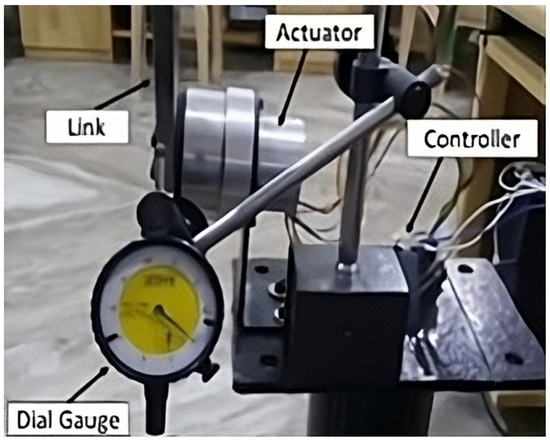
Figure 7.
Repeatability test using the dial gauge.
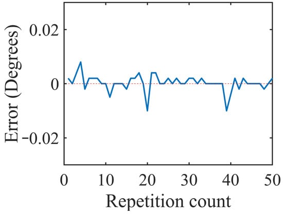
Figure 8.
Position error plot for no load.
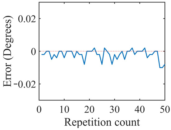
Figure 9.
Position error plot for 33% of the rated load.
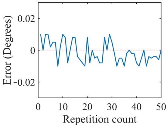
Figure 10.
Position error plot for 66% of the rated load.
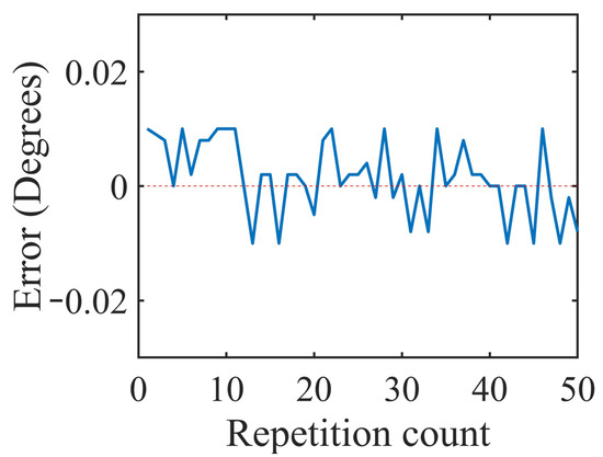
Figure 11.
Position error plot for 100% of the rated load.
The graphs in Figure 8, Figure 9, Figure 10 and Figure 11 were plotted for the errors at the variable loads of 0%, 33%, 66%, and 100% of the rated load, respectively, and the errors in this experiment were defined as the differences between the input position values of the actuator and its actual reach positions. When the actuator moved beyond the input point, then the error had a positive value. If the actuator was not able to reach the desired position and stopped before the input position, then this error was represented with a negative value. The maximum error that occurred was less than 0.003° for all four cases, and the average absolute error was less than 0.0021°. As the load increased, the error in the position also increased, which can be observed in the difference between Figure 8 and Figure 9, but it was less than 0.003°, which was tolerable. The position resolutions of commercial actuators are given in Table 3. The developed actuator had fewer position errors compared to the other actuators listed in Table 3.

Table 3.
Comparison with commercial actuators.
3.2. Velocity Test for Variable Load
From the results of this experiment, we analyzed the deviations of the output angular velocities concerning the input angular velocities for the actuator under varying loads. The input angular velocity represented the velocity supplied to the actuator via the controller interface, while the output angular velocity denoted the instantaneous velocity of the actuator at its output. As shown in Figure 12, the angular velocities were plotted for the different loads, specifically, at 0%, 50%, and 100%. This visualization allowed us to assess how the actuator’s angular velocity responded to changes in load conditions, providing insights into its performance across different operational scenarios.
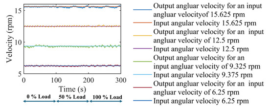
Figure 12.
Velocity deviations for the variable loads.
For each input angular velocity provided, three different load conditions (0%, 50%, and 100% loads) were tested. For instance, when an input angular velocity of 6.25 rpm was supplied to the actuator under these load conditions, the observed output angular velocity deviation from the input velocity fell within the range of −0.28 rpm to 0.18 rpm. Similar deviations for other input angular velocities are documented in Table 4. Overall, considering all cases of varying input angular velocities, as depicted in Figure 12, the deviations in angular velocity at the output of the proposed actuator ranged from −0.22 rpm to 0.19 rpm. It was evident that the deviation in velocity at the actuator output compared to the input remained stable across the different load conditions and did not significantly impact the actuator’s performance.

Table 4.
Angular velocity deviation ranges.
3.3. Torque Analysis for the Variable Applied Current
The experimental setup for the torque analysis test with a variable load is depicted in Figure 13. The torque was directly proportional to the current, and so the current was given as the input to the controller to control the output torque of the actuator. The aluminum link shown in Figure 13 was mounted to the actuator output flange. A weighing machine was used to measure the applied force by the actuator, and it was arranged as shown in Figure 13. When a specific amount of current was provided as an input to the controller, the aluminum link attached to the actuator tried to move and applied force to the weighing machine, as shown in Figure 13. This applied force varied according to the input current. This force was recorded for fifty iterations by each of the different current values. The average value for the fifty readings of force was considered for finding the practical torque provided by the actuator. Table 5 provides information about the theoretical and measured torques of the actuator and the current applied, and Table 6 provides the details of the theoretical and measured relative torques. The theoretical torque was calculated using Equation (5). We observed from Table 5 that the measured torque followed the theoretical torque, with a minimum error percentage of 1.9%.
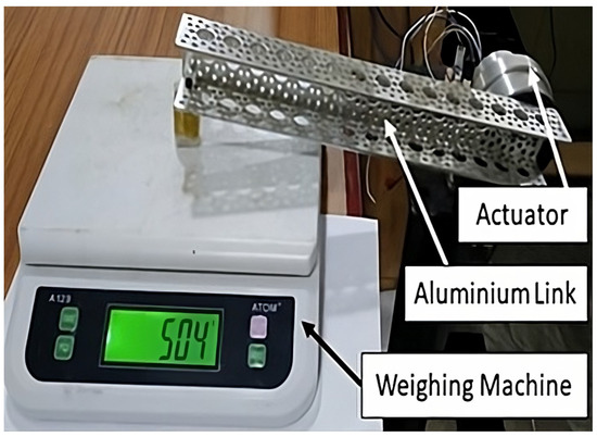
Figure 13.
Torque analysis experimental setup.

Table 5.
Measured torque and theoretical torque analysis, with Kt = 36.9 mNm/A.

Table 6.
Measured relative torque and theoretical relative torque analysis.
4. Conclusions
This paper has presented a thorough exploration of the design, development, and testing phases of a lightweight actuator tailored for high torque and precision in robotics applications. The research delved into modeling the kinematic errors associated with the proposed actuator. The percentage of the kinematic error increased as the weight of the actuator decreased. The challenge was to optimize the kinematic error for a lightweight actuator, which is addressed in this research and which is shown in Table 3. A dedicated test setup was designed and fabricated to validate the functionality and performance of the proposed actuator. This setup provided a controlled environment for conducting the experiments and gathering empirical data to assess the actuator’s capabilities. Through a detailed elucidation of the system’s architecture, SolidWorks modeling, fabrication process, and mathematical modeling, we have provided a comprehensive understanding of the proposed actuator’s capabilities. The experiments conducted, including the position repeatability, velocity tests under variable load, and torque analysis, have demonstrated the actuator’s exceptional precision, stability, and linear characteristics. With a maximum position error of merely 0.003 degrees, a consistent velocity performance across the various load conditions, and a highest torque rating of 20.6 Nm, surpassing its counterparts, our actuator stands out as a promising solution for collaborative robotics applications. The limitation of the proposed actuator is that the torque was measured indirectly using a current, which can always introduce errors because of conversion. This can be addressed using torque sensors which measure the torque directly. Future advancements, including the integration of sensor systems and adaptive control strategies, hold promise for further enhancing the actuator’s performance. Overall, this work contributes to the ongoing evolution of lightweight actuators, paving the way for more efficient and precise robotic systems in diverse fields.
Author Contributions
R.K.M. was responsible for the conceptualization, i.e., the ideas, and the formulation and evolution of the overarching research goals and aims. He conducted the formal analyses, such as the application of the statistical, mathematical, computational, or other formal techniques, to analyze and synthesize the study data. He was also was responsible for the investigations, i.e., conducting the research and investigation processes, and, specifically, he performed the experiments and data/evidence collection. He oversaw the supervision, i.e., the oversight and leadership responsibilities, for the research activities, planning, and execution, including mentorship external to the core team, as well as the development and design of the methodology and the creation of the models, i.e., the methodology. He executed the management and coordination responsibilities for the research activities, planning, and execution, i.e., the project administration. He also handled the preparation, creation, and presentation of the published work, specifically, the writing of the initial draft (including substantive translation), i.e., writing of the original draft and the preparation, creation, and presentation of the published work contributed to by those in the original research group, specifically, the critical review, commentary, and revision, including the pre- and post-publication stages, i.e., the writing (review and editing). S.R.R.V. was responsible for conducting the formal analyses, such as the application of the statistical, mathematical, computational, or other formal techniques, to analyze and synthesize the study data. He was also responsible for the investigations, i.e., conducting the research and investigation processes, and specifically, he performed the experiments and data/evidence collection. He oversaw the methodology for the development and design of the methodology, the creation of the models, and the provision of the study materials, reagents, materials, patients, laboratory samples, animals, instrumentation, computing resources, and other analysis tools, i.e., the resources. S.K.M. conducted the formal analyses, such as the application of the statistical, mathematical, computational, or other formal techniques, to analyze and synthesize the study data. He was also responsible for the investigations, i.e., conducting the research and investigation processes, and specifically, he performed the experiments and data/evidence collection. He oversaw the methodology for the development and design of the methodology, the creation of the models, and the provision of the study materials, reagents, materials, patients, laboratory samples, animals, instrumentation, computing resources, and other analysis tools, i.e., the resources. B.T.P. performed the software programming and software development. He also performed the verification of the overall replication/reproducibility of the results/experiments and other research outputs, i.e., the validation. S.R.S. performed the implementation of the computer code and the supporting algorithms. He also performed the verification of the overall replication/reproducibility of the results/experiments and other research outputs, i.e., the validation. U.S.C.G. tested the existing code components and performed the verification of the overall replication/reproducibility of the results/experiments and other research outputs, i.e., the validation. All authors have read and agreed to the published version of the manuscript.
Funding
This research received no external funding.
Data Availability Statement
The datasets generated during and/or analyzed during the current study are available from the corresponding author upon reasonable request.
Acknowledgments
The authors sincerely thank the Electronics and Communication Engineering department and the Humanitarian Technology (HuT) Labs of Amrita Viswa Vidyapeetham, Amritapuri Campus, for their help and support in conducting this research.
Conflicts of Interest
The authors declare no conflicts of interest that are relevant to the contents of this article. The authors have no relevant financial or non-financial interests to disclose. The funders had no role in the design of the study; in the collection, analyses, or interpretation of data; in the writing of the manuscript; or in the decision to publish the results.
References
- Megalingam, R.K.; Manoharan, S.K.; Mohan, S.M.; Vadivel, S.R.R.; Gangireddy, R.; Ghanta, S.; Kotte, S.; Perugupally, S.T.; Sivanantham, V. Amaran: An Unmanned Robotic Coconut Tree Climber and Harvester. IEEE/ASME Trans. Mechatron. 2021, 26, 288–299. [Google Scholar] [CrossRef]
- Megalingam, R.K.; Vadivel, S.R.R.; Rajendraprasad, A.; Raj, A.; Baskar, S.; Babu, R.B.M. Development and evaluation of a search-and-rescue robot Paripreksya 2.0 for WRS 2020. Adv. Robot. 2022, 36, 1120–1133. [Google Scholar] [CrossRef]
- Wang, Z.; Liu, Z.; Ma, Q.; Cheng, A.; Liu, Y.-H.; Kim, S.; Deguet, A.; Reiter, A.; Kazanzides, P.; Taylor, R.H. Vision-Based Calibration of Dual RCM-Based Robot Arms in Human-Robot Collaborative Minimally Invasive Surgery. IEEE Robot. Autom. Lett. 2018, 3, 672–679. [Google Scholar] [CrossRef]
- Megalingam, R.K.; Rajendraprasad, A.; Raj, A.; Raghavan, D.; Teja, C.R.; Sreekanth, S.; Sankaran, R. Self-E: A self-driving wheelchair for elders and physically challenged. Int. J. Intell. Robot. Appl. 2021, 5, 477–493. [Google Scholar] [CrossRef]
- Megalingam, R.K.; Raj, A.; Manoharan, S.K.; Egumadiri, V. App Based Teleoperated UV Disinfectant Robot for COVID Cause. In Proceedings of the 2021 Second International Conference on Electronics and Sustainable Communication Systems (ICESC), Coimbatore, India, 4–6 August 2021; pp. 277–281. [Google Scholar] [CrossRef]
- Megalingam, R.K.; Manoharan, S.K.; Mohandas, S.M.; Reddy, C.P.K.; Vijay, E.; Naveen, P.N.V.K.; Chandrika, D. Wearable Hand Orthotic Device for Rehabilitation: Hand Therapy with Multi-Mode Control and Real-Time Feedback. Appl. Sci. 2023, 13, 3976. [Google Scholar] [CrossRef]
- Li, A.; Ye, L.; Yanqing, J.; Yueming, L.; Jian, C.; Jiayu, H. Soft-Switching Proximate Time Optimal Heading Control for Underactuated Autonomous Underwater Vehicle. IEEE Access 2019, 7, 143233–143249. [Google Scholar] [CrossRef]
- Liu, B.; Fu, W.; Wang, W.; Gao, Z.; Li, R.; Peng, L.; Du, H.; Chen, X. Research on Cobot Action Decision-Making Method Based on Intuitionistic Fuzzy Set and Game Theory. IEEE Access 2022, 10, 103349–103363. [Google Scholar] [CrossRef]
- Van de Perre, G.; Hubert, T.; Verstraten, T.; Vanderborght, B. Investigating the Potential of Flexible Links for Increased Payload to Mass Ratios for Collaborative Robotics. IEEE Access 2023, 11, 15981–15995. [Google Scholar] [CrossRef]
- Zhang, W.; Xu, Y.; Zhou, G. Research on a Novel Transverse Flux Permanent Magnet Motor with Hybrid Stator Core and Disk-Type Rotor for Industrial Robot Applications. IEEE Trans. Ind. Electron. 2021, 68, 11223–11233. [Google Scholar] [CrossRef]
- Salah, M.; Al-Jarrah, A.; Tatlicioglu, E.; Banihani, S. Robust Backstepping Control for a Four-Bar Linkage Mechanism Driven by a DC Motor. J. Intell. Robot. Syst. 2019, 94, 327–338. [Google Scholar] [CrossRef]
- Lin, N.; Wu, P.; Wang, M.; Wei, J.; Yang, F.; Xu, S.; Ye, Z.; Chen, X. IMU-Based Active Safe Control of a Variable Stiffness Soft Actuator. IEEE Robot. Autom. Lett. 2019, 4, 1247–1254. [Google Scholar] [CrossRef]
- Pan, Y.; Li, X.; Yu, H. Efficient PID Tracking Control of Robotic Manipulators Driven by Compliant Actuators. IEEE Trans. Control Syst. Technol. 2019, 27, 915–922. [Google Scholar] [CrossRef]
- Legrand, J.; Loenders, B.; Vos, A.; Schoevaerdts, L.; Poorten, E.V. Integrated Capacitance Sensing for Miniature Artificial Muscle Actuators. IEEE Sens. J. 2020, 20, 1363–1372. [Google Scholar] [CrossRef]
- Tazaki, Y. Parallel link-based light-weight leg design for bipedal robots. In Proceedings of the IEEE-RAS 19th International Conference on Humanoid Robots (Humanoids), Toronto, ON, Canada, 15–17 October 2019. [Google Scholar] [CrossRef]
- Megalingam, R.K.; Vadivel, S.R.R.; Prem, A.; Avvari, V.S.Y.; Sairam, B.C.S.C.; Konduri, S. Test Setup for Analysis of Torque on DC Motor Shaft and its Possible Applications. In Proceedings of the International Conference on Communication and Signal Processing (ICCSP), Chennai, India, 4–6 April 2019. [Google Scholar]
- Refael, G.; Degani, A. A Single-Actuated Swimming Robot: Design, Modelling, and Experiments. J. Intell. Robot. Syst. 2019, 94, 471–489. [Google Scholar] [CrossRef]
- Tallapragada, P. A swimming robot with an internal rotor as a nonholonomic system. In Proceedings of the 2015 American Control Conference (ACC), Chicago, IL, USA, 1–3 July 2015; pp. 657–662. [Google Scholar] [CrossRef]
- Nerat, M.; Vrancic, D. A Novel Fast-Filtering Method for Rotational Speed of the BLDC Motor Drive Applied to Valve Actuator. IEEE/ASME Trans. Mechatron. 2016, 21, 1479–1486. [Google Scholar] [CrossRef]
- Megalingam, R.K.; Vadivel, S.R.R.; Pula, B.T.; Sathi, S.R.; Gupta, U.S.C. Motor Control Design for Position Measurement and Speed Control. In Proceedings of the International Conference on Communication and Signal Processing, Chennai, India, 4–6 April 2019. [Google Scholar]
- Terfurth, J.; Schmid, M.; Parspour, N. Planar Aligned Transverse Flux Machine with Integrated Reduction Gear. In Proceedings of the 2020 International Conference on Electrical Machines (ICEM), Gothenburg, Sweden, 23–26 August 2020; pp. 714–720. [Google Scholar] [CrossRef]
- Terfurth, J.; Waldhof, M.; Schmid, M.; Weber, J.; Keller, M.; Parspour, N. Design and Evaluation of a Spatially Distributed and Gear-Integrated Transverse Flux Machine. IEEE Trans. Ind. Electron. 2023, 70, 5065–5073. [Google Scholar] [CrossRef]
- Kendjouh, T.; Guerroudj, C.; Charpentier, J.-F.; Bracikowski, N.; Hadjout, L.; Bekhouche, L. Contribution to Improve Magnetic Performance and Torque Ripple Reduction of the Low-Speed DSPM Machine. Actuators 2023, 12, 195. [Google Scholar] [CrossRef]
- Varshney, A.; Dwivedi, B. Performance analysis of a BLDC drive under varying load. In Proceedings of the IEEE 1st International Conference on Power Electronics, Intelligent Control and Energy Systems, Delhi, India, 4–6 July 2016. [Google Scholar]
- Schmitt, L.; Conrad, P.; Kopp, A.; Ament, C.; Hoffmann, M. Non-Inchworm Electrostatic Cooperative Micro-Stepper-Actuator Systems with Long Stroke. Actuators 2023, 12, 150. [Google Scholar] [CrossRef]
- Aditya, K.; Udupa, G.; Sreedharan, P. Robotic gripper drive by flexible microactuator based on an innovative technique. In Proceedings of the 2010 IEEE Workshop on Advanced Robotics and its Social Impacts, Seoul, Republic of Korea, 26–28 October 2010. [Google Scholar]
- Taufer, T.; Billet, L. Compact BLDC & stepper motor technology for ultra-slim actuators. In Proceedings of the IKMT 2015; 10. ETG/GMM-Symposium Innovative Small Drives and Micro-Motor Systems, Cologne, Germany, 14–15 September 2015; pp. 1–6. [Google Scholar]
- KinovaActuator. Available online: https://www.kinovarobotics.com/sites/default/files/AS-ACT-KA58-KA75-SP-INT-EN%202018041.2%20%28KINOVA%E2%84%A2%20Actuator%20series%20KA75%2B%20KA-58%20Specifications%29 (accessed on 22 February 2024).
- Hebi-Robotics. Available online: http://docs.hebi.us/resources/datasheets/X-eriesDatasheet.pdf (accessed on 22 February 2024).
Disclaimer/Publisher’s Note: The statements, opinions and data contained in all publications are solely those of the individual author(s) and contributor(s) and not of MDPI and/or the editor(s). MDPI and/or the editor(s) disclaim responsibility for any injury to people or property resulting from any ideas, methods, instructions or products referred to in the content. |
© 2024 by the authors. Licensee MDPI, Basel, Switzerland. This article is an open access article distributed under the terms and conditions of the Creative Commons Attribution (CC BY) license (https://creativecommons.org/licenses/by/4.0/).