Abstract
A new design for humanoid arms is presented based on a tripod mechanism that is actuated by linear servomotors. A specific prototype is built and tested, with the results of performance characterization verifying a possible implementation on the LARMbot humanoid. The design solves the main requirements in terms of a high payload ratio with respect to arm weight by using a tripod architecture with parallel manipulator behavior. The built prototype is assembled with commercial components to match the expectations for low-cost user-oriented features. The test results show satisfactory operation characteristics both in motion and force performance, which will ensure a future successful implementation in the LARMbot humanoid structure.
1. Introduction
Humanoid robots, as used in research and applications, including market solutions, are designed with a mechanical structure that is strongly inspired by human anatomy. Since the first humanoid robot, WABOT-1, was designed by Ikiro Katao in the early 1970s at Waseda University in Tokyo, Japan [1], the limbs have been conceived with bulky anthropomorphic-shaped structures with actuators and sensors. Examples of these humanoid robots include famous solutions with very successful designs such as ASIMO [2], WABIAN [3], HRP [4], Johnnie and Lola [5], HUBO [6], ATLAS [7], and BHR [8]. These robots represent different experiences with similarities in activities worldwide.
Today, challenges for humanoid robots can be still recognized in terms of increasing humanoid capabilities, such as walking on various unstructured terrains, preventing falls and/or including suitable protections [9,10,11,12], and advanced cognitive-based interaction with the environment and humans [13,14,15,16,17]. In current humanoids, the arms are designed with anthropomorphic structures [18,19,20], which, although replicating the characteristics and capabilities of the human arm, show limitations, especially in load capacity, due to the serial kinematic structure with revolute joints [21,22].
Humanoid solutions have been attempted and investigated, spanning from very sophisticated and complex features to very simple low-cost operation-limited capabilities. Indeed, there is a growing interest in the community towards practical solutions, mainly in service fields, focusing on solutions with low-cost user-oriented designs, even if they have limited capabilities. Among these research interests, the LARMbot humanoid has been developed with different conceptual designs since the beginning of the 2000s, and a prototype was developed in 2016 [23,24,25]. The LARMbot humanoid is characterized by a low-cost efficient design that is based on parallel mechanism architectures using market components and 3D-printed parts. The parallel mechanism architectures used in all the main body parts are aimed at providing good performance in motion and force capacity, inspired by the muscle–skeleton human anatomy, despite the limited characteristics of the components and 3D-printed parts [24]. In particular, the limb structure has been designed using the simplest parallel tripod architecture by replicating the functioning of the muscle–skeleton human anatomy with synergistic and antagonistic features [25]. However, experiences with the built prototypes have highlighted possibilities for improvement by revising the original designs and attempting to have common structures for the limbs.
In this paper, considering previous designs and experiences reported, for example, in [23,24,25], a new tripod-based mechanism is presented for a new humanoid arm based on a 3-SPR joint mechanism. The tripod structure mechanism is actually well known and applied in robotics, but mainly in industrial manipulators, such as Tricept made by various robot manufacturers. However, in the case of humanoid robots, it is a novelty because the structures of the arms of humanoid robots are designed with an anthropomorphic serial kinematic chain structure, with parallel kinematic chain structures using the actuating part as a parallel kinematic chain being rare. A redesigned solution is developed with features that can be used for both legs and arms by looking at the similarities of human muscle–skeleton limb structures, with the functioning based on the synergistic and antagonistic operation of the muscles. A prototype solution for a humanoid arm is built with the LARMbot characteristics of low-cost user-oriented design and operation by using market components and 3D-printed parts. The feasibility of the prototype is tested successfully, including a characterization of the operation performance of the tripod-based arm, whose features are well suited for an improvement of the humanoid LARMbot.
2. Materials and Methods
The conceptual design of a tripod mechanism for a humanoid arm is developed based on the requirements and motivations, which also helps in defining a practical solution that is well-suited for future improvements of the LARMbot humanoid. The materials considered for this development include market components and 3D-printed parts, which are fundamental aspects to achieve the expected low-cost user-oriented solution. The methods for design definition are based on the kinematic design of a tripod parallel mechanism and its CAD modeling, leading to a prototype construction that can be useful for implementation in a new LARMbot humanoid. These methods are also useful for the validation and characterization of the obtained new humanoid arm design.
2.1. Design and Operation Requirements
The requirements for the design and construction of a prototype for a new humanoid arm were defined considering the functionality of the previous humanoid prototype, as shown in Figure 1a, with particular reference to the leg and arm structures subsequently tested, as shown in Figure 1b,c. Furthermore, the requirements and peculiarities of the structures and operations for humanoid robots, shown in Figure 2, were considered for the implementation of the tripod structure and also for the humanoid arm, as per improvements in functional performance as well as structural compactness.
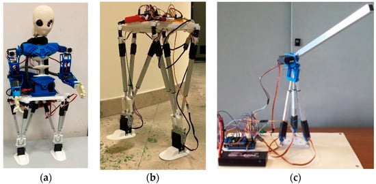
Figure 1.
LARMbot humanoid: (a) 2018 full prototype [23,24]; (b) leg module prototype in 2020; (c) new arm prototype in 2021 [25].
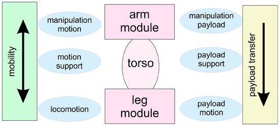
Figure 2.
A scheme for design and operation requirements.
In particular, in Figure 1a [23,24], we want to emphasize how the humanoid robot LARMbot is characterized by mechanisms with a parallel structure in the torso, based on a parallel cable actuation mechanism. This determines a wide range of movement for the torso, approximately 20 deg in all directions, as well as a high load capacity of approximately 10 kg along with its own weight of 800 g. At the time LARMbot was conceived, this torso solution suggested the implementation of a parallel manipulator for the legs, which was designed as shown in Figure 1a, with a mechanism using three actuators non-converging at the ankle point with operating complexity that was overcome with the solution shown in Figure 1b [25] by adopting the tripod architecture. The positive experience with the structure shown in Figure 1b for the legs, which ensured an improvement in the range of movement of approximately 30 degrees in all directions with a load capacity similar to that of the torso, suggested adopting the tripod architecture also for the arm structure, but with a hybrid solution represented in Figure 1c [23,24]. The first experience of this new humanoid arm with the hybrid parallel–serial kinematic structure is based on the tripod part of the arm that creates the shoulder joint, resulting in a larger load capacity and robustness of the full arm. The serial part of the forearm with the elbow joint still showed limited functionality both in the range of movement and in the load capacity, affecting the entire structure of the humanoid arm so much as to suggest the implementation of a tripod mechanism for the entire arm when adequately sized, with dimensions well-proportioned to the humanoid’s torso.
A revised consideration of the entire humanoid structure with its fundamental functional capabilities was necessary in order to define characteristic requirements for a new humanoid arm that will be integrated into the humanoid structure to ensure synergy and coordination typical for humanoid functioning. In Figure 2, the structural and functional characteristics are summarized by considering a modular structure of a humanoid with the subsystems of legs, torso, and arms that ensure the typical humanoid coordinated characteristics of manipulation and locomotion with adequate load capacity. In particular, it is indicated that the requirements and mobility characteristics of a humanoid can depend on the movement coordination of all three modules, requiring adequate proportionate design. Furthermore, it is emphasized that the load capacity of a humanoid depends on the three modules in a sequential manner; i.e., the load capacity of the arm system for manipulation depends on the support capacity of the torso and finally on the capability of the legs to support the entire structure loaded by the load. Therefore, the structure and functionality of a humanoid arm must be thought of and conditioned by the structural and functional characteristics according to the characteristics of the torso and the legs, as well as the function of the purposes designed for the entire structure.
In consideration of the summary presented in Figure 1 and Figure 2, the requirements for designing a new humanoid arm with a tripod structure for the LARMbot humanoid can be summarized as follows: a length of approximately 50 cm, proportionate to the structure of the torso, with a mobility of approximately 30 degrees and a load capacity of approximately 5 kg, consistent with that ensured by the torso and legs.
2.2. Design Solution with Tripod Mechanism
The tripod structure of the new humanoid arm for LARMbot is presented in Figure 3. In particular, Figure 3a shows the conceptual design of the arm, including the wrist joint on which a two-fingered hand is installed. The scheme also shows the respective actuators m1 and m2, which are part of the load for the tripod mechanism that is operated by the three links with linear actuators L1, L2, and L3. The fixed platform creates an attachment plate on the torso structure as the shoulder frame, while the mobile platform is created with the plate on the convergence mechanism of the three links where the m1 wrist motor is installed. The shoulder frame is designed as the base frame of the tripod architecture with a specific symmetric configuration of an equilateral triangle to facilitate the assembly configuration as a function of the main expected performance direction. The functional kinematic design is represented by the model in Figure 3, which indicates the universal-type joints for the connections of the linear actuators to the plate of the shoulder platform, the linear joints for the actuated tripod links, and finally, the convergence joint of the three links with the original three-body mechanism connected by a system of five revolute pairs, as presented in [25].
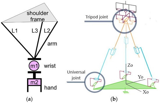
Figure 3.
New design of humanoid arm based on tripod mechanism: (a) conceptual scheme; (b) kinematic design.
Figure 4 shows the CAD design developed for the realization of the kinematic design shown in Figure 3b, modeling commercial components for the universal joints and the linear actuators that create the tripod architecture, while the structural and support parts were modeled for manufacturing using lab 3D printing technology. These commercial components and 3D-printed parts have been selected and developed with the characteristics of low cost and easy use in both the assembly and operational functioning of the prototype. In particular, the geometries of the parts have been designed as a function of the dimensions that can ensure rigidity and solidity, as well as dimensional compactness, considering solutions that are easy to produce via 3D printer using commercial PLA.
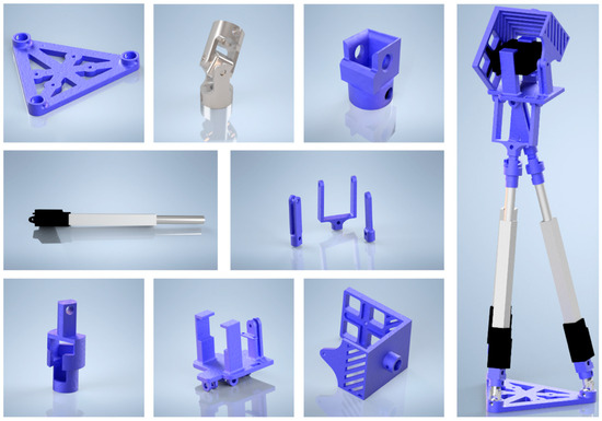
Figure 4.
CAD design of the humanoid arm of the tripod arm shown in Figure 3 with 3D-printed parts and commercial linear actuators.
2.3. Prototype Assembly
The CAD model shown in Figure 4 was also used to verify the structural and functional feasibility of the arm structure proposed in Figure 3 in order to produce the prototype shown in Figure 5a. Figure 4 shows the components used to build the prototype in Figure 5a using commercial products, and the parts were adequately produced using a 3D printer.
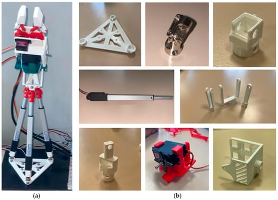
Figure 5.
Prototype of the humanoid tripod arm of the arm shown in Figure 5: (a) full arm; (b) 3D-printed parts, and commercial linear actuators.
The prototype is characterized by a light structure with parts that are easily replaceable, and the assembly is based on simple connections fixed with small screws, facilitating both proper fixing and easy disassembly if necessary. The characteristic elements are the three linear actuators which create the tripod structure that is secured by the 3-axis converging mechanism. The mobile platform of the 3-axis converging houses the wrist actuator whose mobile frame is equipped with a two-finger gripper operated by a small servomotor.
The prototype thus constructed meets the requirements and expectations for a compact and efficient humanoid arm for LARMbot measuring approximately 40 cm in length, including the two-finger hand, with a shoulder attachment plate of 10 × 10 × 10 cm3, for a total weight of approximately 300 g. The overall cost of the prototype can be estimated at less than EUR 400.
2.4. Modeling
The prototype can be moved by using a model-based algorithm that determines the position of the wrist joint from lengths L1, L2, and L3 of each linear actuator. To solve the forward kinematic problem with reference to the frame in Figure 3b, the position of the center of the tripod joint can be computed as the intersection of three spheres, each centered on one of the base universal joints (located at a distance of length a from the reference frame and equally spaced around the z-axis), with a radius equal to the length of the respective actuator:
These closed-form Equations (1)–(3) represent the kinematic problem of the system that has been solved to obtain the open-loop controlled motion in the desired paths for testing the prototypes’ performance.
3. Results
Several laboratory tests were conducted to validate and characterize the structure and function of the arm prototype for the LARMbot humanoid. Tests were carried out to verify the ability to move and manipulate the hand and a load using the two-finger hand. The reported results refer to tests for the validation of the proposed design, including initial performance characterization. The tests were conducted to assess the maximum motion range with an open-loop controlled operation.
Figure 6 shows snapshots of the two experiments that highlight the satisfactory performance of the prototype in these modes. Figure 6a shows a manipulation test with no load on the hand, while Figure 6b shows a test with a load made of a piece of metal of about 200 g. The test results are shown in Figure 7, Figure 8 and Figure 9, using the data acquired from the sensors appropriately installed to monitor the functionality of the prototype in terms of movement and power consumption. They are installed with a design that does not limit the arm motion and can also be used for future motion control.
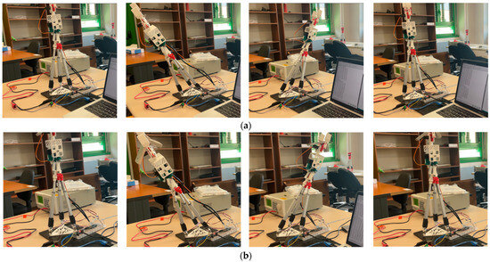
Figure 6.
Snapshots of the test: (a) without payload; (b) with payload.

Figure 7.
Acquired results during the test shown in Figure 6 in terms of angles: (a) without load; (b) with load.

Figure 8.
Acquired results during the test shown in Figure 6 in terms of acceleration of wrist point: (a) without load; (b) with load.

Figure 9.
Acquired results during the test in Figure 6 in terms of current consumption: (a) without load; (b) with load.
An IMU sensor is installed on the wrist platform to monitor the motion in terms of angles and linear acceleration with respect to an internal reference system with the XY plane lying on the platform in the wrist. The angles are measured around the X- and Y-axes, while the linear accelerations are evaluated with respect to the reference axes. The IMU acquisitions are referred to as an XYZ reference system on the fixed platform, as shown in Figure 3b, with the home configuration labeled as XoYoZo.
A current acquisition sensor is used to evaluate power consumption to ensure the efficiency of future implementation on the LARMbot humanoid, considering the need to limit power usage according to the capacity of the humanoid’s batteries to ensure its autonomy.
Figure 7 shows the movement results of the two tests in terms of the bending angles around the X- and Y-directions, which show a sufficiently gradual and regular movement with a maximum range of just over 60 deg. It should be noted that, in the case of manipulation with a load, as shown in Figure 7b, the characteristics of the angular motion are preserved even if a vibration is noted between 6.0 and 8.0 s, probably due to the movement of the load inside the hand. The range of motion of the built prototype reaches more than 60 deg, as indicated in the results shown in Figure 7, and is quite close to the theoretical possible motion range of the kinematic design.
The acceleration of the plots shown in Figure 8 refers to the acceleration sensed by the IMU that is installed on the wrist. Figure 8 shows the plots of the acceleration components acquired in the two tests, which confirm the fact that the load does not seem to significantly influence the characteristics of the motion since the time evolution and the numerical values are preserved, despite encountering a certain variation in the interval between 6.0 and 8.0 s. Considering the lack of excessive speed in the movement tested in cycles of approximately 5 s, the accelerations are modest in numerical value, showing an efficient smoothness of movement of the arm in both modes.
Finally, as shown in Figure 9, the acquisition of the actuation current for all the actuators of the tripod, including the wrist to keep it in a stationary position, shows a cyclical trend corresponding well to the tested movement of alternating inclination, especially along the Y direction as indicated in Figure 7, with a current variation limited to approximately a maximum of 350 mA. This trend of the power supply current, and therefore of power consumption, is not only acceptable for the actuators used but it is well-suited to the expected limited power consumption. The characteristics of the energy consumed by the prototype are investigated with the reported test results in Figure 9, in terms of servomotor feeding current at 12 V during open-loop controlled motion at the maximum range, swinging in all directions with and without a heavy payload. The good results can be represented by a maximum of 350 mA during motion with no payload against a maximum of 420 mA during motion with a payload.
In summary, the tested prototype, although not exhibiting high performance, works satisfactorily with the expected motion capability and load capacity (200 g against a full arm weight of about 300 g) that can be properly used when implementing the arm in the torso of the LARMbot humanoid. Future work can be planned to improve the motion range and payload capacity of the arm design with better linear actuators, both with increased stroke and force capacity.
4. Conclusions
The need to review the design of the arm for the LARMbot humanoid in order to have similar characteristics as other humanoid modules was addressed by revising the design requirements, aiming at a solution that satisfies the peculiar characteristics of the LARMbot in terms of compactness, motion capabilities, and payload by using mechanism structures with parallel architecture. The arm is designed with a tripod structure similar to the one already implemented for the legs of the LARMbot humanoid, with a design that is aimed at using low-cost components and non-commercial parts produced via 3D printing. The built prototype shows satisfactory characteristics, as reported by the results of the experimental tests conducted to validate and characterize the prototype in terms of performance in motion and load capacity. The motion range is detected with a range of more than 60 deg and the payload capacity is validated, with a ratio nearly equal to one with respect to the arm’s own weight while using 420 mA for servomotor feeding.
Author Contributions
Conceptualization, M.C., M.R. and S.B.; methodology, M.C. and S.B.; software, S.B.; validation, M.R. and S.B.; formal analysis, M.C., M.R. and S.B.; investigation, M.C., M.R. and S.B.; resources, M.C.; data curation, M.R. and S.B.; writing—original draft preparation, M.C. and S.B.; writing—review and editing, M.C., M.R. and S.B.; visualization, M.C. and S.B.; supervision M.C.; project administration, M.C.; funding acquisition, M.C. All authors have read and agreed to the published version of the manuscript.
Funding
This research received no external funding.
Data Availability Statement
The original contributions presented in the study are included in the article, further inquiries can be directed to the corresponding author.
Acknowledgments
The second author wishes to thank SeaTech-School of Engineering, University of Toulon, France, for the support of an internship period at the laboratory of Robot Mechatronics of the University of Rome Tor Vergata during 2023.
Conflicts of Interest
The authors declare no conflicts of interest.
References
- Lim, H.-O.; Takanishi, A. Biped Walking Robots Created at Waseda University: WL and WABIAN Family. Philos. Trans. R. Soc. A Math. Phys. Eng. Sci. 2007, 365, 49–64. [Google Scholar] [CrossRef] [PubMed]
- Sakagami, Y.; Watanabe, R.; Aoyama, C.; Matsunaga, S.; Higaki, N.; Fujimura, K. The intelligent ASIMO: System overview and integration. In Proceedings of the IEEE/RSJ International Conference on Intelligent Robots and Systems, Lausanne, Switzerland, 30 September–4 October 2002; pp. 2478–2483. [Google Scholar] [CrossRef]
- Ogura, Y.; Aikawa, H.; Shimomura, K.; Kondo, H.; Morishima, A.; Lim, H.O.; Takanishi, A. Development of a new humanoid robot WABIAN-2. In Proceedings of the 2006 IEEE International Conference on Robotics and Automation, ICRA 2006, Orlando, FL, USA, 15–19 May 2006; pp. 76–81. [Google Scholar] [CrossRef]
- Kaneko, K.; Kanehiro, F.; Kajita, S. Humanoid Robot HRP-2. In Proceedings of the IEEE International Conference on Robotics and Automation, New Orleans, LA, USA, 26 April–1 May 2004; pp. 1083–1090. [Google Scholar] [CrossRef]
- Buschmann, T.; Gienger, M. TUM Robots (e.g., Johnnie, Lola). In Humanoid Robotics: A Reference; Goswami, A., Vadakkepat, P., Eds.; Springer: Dordrecht, The Netherlands, 2017. [Google Scholar] [CrossRef]
- Oh, J.-H.; Hanson, D.; Kim, W.-S.; Han, Y.; Kim, J.-Y.; Park, I.-W. Design of Android type Humanoid Robot Albert HUBO. In Proceedings of the 2006 IEEE/RSJ International Conference on Intelligent Robots and Systems, Beijing, China, 9–15 October 2006; pp. 1428–1433. [Google Scholar] [CrossRef]
- Kuindersma, S.; Deits, R.; Fallon, M.; Valenzuela, A.; Dai, H.; Permenter, F.; Koolen, T.; Marion, P.; Tedrake, R. Optimization-based locomotion planning, estimation, and control design for the atlas humanoid robot. Auton. Robot. 2016, 40, 429–455. [Google Scholar] [CrossRef]
- Yu, Z.; Huang, Q.; Ma, G.; Chen, X.; Zhang, W.; Li, J.; Gao, J. Design and development of the humanoid robot BHR-5. Adv. Mech. Eng. 2014, 6, 852937. [Google Scholar] [CrossRef]
- Chignoli, M.; Kim, D.; Stanger-Jones, E.; Kim, S. The MIT humanoid robot: Design, motion planning, and control for acrobatic behaviors. In Proceedings of the 2020 IEEE-RAS 20th International Conference on Humanoid Robots (Humanoids), Munich, Germany, 19–21 July 2021; pp. 1–8. [Google Scholar]
- Kashyap, A.K.; Parhi, D.R.; Muni, M.K.; Pandey, K.K. A hybrid technique for path planning of humanoid robot NAO in static and dynamic terrains. Appl. Soft Comput. 2020, 96, 106581. [Google Scholar] [CrossRef]
- Ayala, A.; Cruz, F.; Campos, D.; Rubio, R.; Fernandes, B.; Dazeley, R. A comparison of humanoid robot simulators: A quantitative approach. In Proceedings of the 2020 Joint IEEE 10th International Conference on Development and Learning and Epigenetic Robotics (ICDL-EpiRob), Valparaiso, Chile, 26–30 October 2020; pp. 1–6. [Google Scholar]
- Darvish, K.; Penco, L.; Ramos, J.; Cisneros, R.; Pratt, J.; Yoshida, E.; Ivaldi, S.; Pucci, D. Teleoperation of humanoid robots: A survey. IEEE Trans. Robot. 2023, 39, 1706–1727. [Google Scholar] [CrossRef]
- Fox, J.; Gambino, A. Relationship development with humanoid social robots: Applying interpersonal theories to human–robot interaction. Cyberpsychol. Behav. Soc. Netw. 2021, 24, 294–299. [Google Scholar] [CrossRef] [PubMed]
- Mara, M.; Stein, J.P.; Latoschik, M.E.; Lugrin, B.; Schreiner, C.; Hostettler, R.; Appel, M. User responses to a humanoid robot observed in real life, virtual reality, 3D and 2D. Front. Psychol. 2021, 12, 633178. [Google Scholar] [CrossRef] [PubMed]
- Mukherjee, S.; Baral, M.M.; Pal, S.K.; Chittipaka, V.; Roy, R.; Alam, K. Humanoid robot in healthcare: A systematic review and future research directions. In Proceedings of the 2022 International Conference on Machine Learning, Big Data, Cloud and Parallel Computing (COM-IT-CON), Faridabad, India, 26–27 May 2022; Volume 1, pp. 822–826. [Google Scholar]
- Yousif, J. Humanoid robot as assistant tutor for autistic children. Int. J. Comput. Appl. Sci. 2020, 8, 8–13. [Google Scholar]
- Kiilavuori, H.; Sariola, V.; Peltola, M.J.; Hietanen, J.K. Making eye contact with a robot: Psychophysiological responses to eye contact with a human and with a humanoid robot. Biol. Psychol. 2021, 158, 107989. [Google Scholar] [CrossRef] [PubMed]
- Yang, A.; Chen, Y.; Naeem, W.; Fei, M.; Chen, L. Humanoid motion planning of robotic arm based on human arm action feature and reinforcement learning. Mechatronics 2021, 78, 102630. [Google Scholar] [CrossRef]
- Ramón, J.L.; Calvo, R.; Trujillo, A.; Pomares, J.; Felicetti, L. Trajectory optimization and control of a free-floating two-arm humanoid robot. J. Guid. Control Dyn. 2022, 45, 1661–1675. [Google Scholar] [CrossRef]
- Wei, Y.; Zhao, J. Designing human-like behaviors for anthropomorphic arm in humanoid robot NAO. Robotica 2020, 38, 1205–1226. [Google Scholar] [CrossRef]
- Huang, K.; Xian, Y.; Zhen, S.; Sun, H. Robust control design for a planar humanoid robot arm with high strength composite gear and experimental validation. Mech. Syst. Signal Process. 2021, 155, 107442. [Google Scholar] [CrossRef]
- Chowdhury, D.; Park, Y.E.; Jung, I.; Lee, S. Characterization of Exterior Parts for 3D-Printed Humanoid Robot Arm with Various Patterns and Thicknesses. Polymers 2024, 16, 988. [Google Scholar] [CrossRef] [PubMed]
- Ceccarelli, M. A History of LARMbot humanoid. In Proceedings of the of 2024 IFToMM Symposium on History of Machines and Mechanism, Ankara, Türkiye, 18–20 April 2024. Paper No. 23, in print. [Google Scholar]
- Ceccarelli, M.; Russo, M.; Morales-Cruz, C. Parallel Architectures for Humanoid Robots. Robotics 2020, 9, 75. [Google Scholar] [CrossRef]
- Fort, A.; Laribi, M.A.; Ceccarelli, M. Design and performance of a LARMbot PK arm prototype. Int. J. Humanoid Robot. 2022, 19, 2250009. [Google Scholar] [CrossRef]
Disclaimer/Publisher’s Note: The statements, opinions and data contained in all publications are solely those of the individual author(s) and contributor(s) and not of MDPI and/or the editor(s). MDPI and/or the editor(s) disclaim responsibility for any injury to people or property resulting from any ideas, methods, instructions or products referred to in the content. |
© 2024 by the authors. Licensee MDPI, Basel, Switzerland. This article is an open access article distributed under the terms and conditions of the Creative Commons Attribution (CC BY) license (https://creativecommons.org/licenses/by/4.0/).