Abstract
A hydraulic support is one of the most important pieces of equipment in fully mechanized coal mining, and its stability and reliability will have a direct impact on fully mechanized coal mining. In order to deeply elucidate the dynamic working characteristics of a hydraulic support during lifting, lowering, and moving, and to provide theoretical support for further optimizing the stability and reliability of a hydraulic support, the dynamic characteristics of a hydraulic support are studied in this paper. Firstly, in order to study the dynamic working characteristics of hydraulic support lifting, a rigid–flexible coupling dynamic simulation model of a hydraulic support is established; in order to study the dynamic working characteristics of hydraulic support moving, a microcontact dynamic model of a hydraulic support and the caving face roof and floor based on G-W contact theory is proposed, and the first rigid–flexible–mechanical–hydraulic coupling dynamic simulation system of a hydraulic support and the roof and floor of a caving face is established in the industry. Then, based on this foundation, simulation experiments are conducted for hydraulic support lifting, moving without pressure, and moving with pressure, respectively. The working characteristic parameters of the hydraulic support are collected and analyzed. The results show that working speed, working height, surface contact conditions, residual working resistance, and impact load have different effects on the stability and reliability of the hydraulic support. This study can provide in-depth technical support and theoretical guidance for understanding and improving the dynamic working characteristics of the hydraulic support.
1. Introduction
Coal is China’s most important primary energy source. Up to 2050, coal will still make up over 54 per cent of Chinese energy consumption. Therefore, in the near and long term, the safety, efficiency, and cleanliness of coal resources will remain a significant problematic for Chinese coal industry [1,2,3]. Intelligent mining is the key link to realize the intelligentization of coal mines, and it is also the core technical means to reduce the number of caving faces and ensure the safety of personnel [4,5,6]. The automated continuous and stable coordinated operation of a set of fully mechanized mining equipment is the foundation of smart mining [7,8]. A hydraulic support provides a safe working space for caving face and promotes its operation through interaction with surrounding rock and mining equipment. It is one of the most significant pieces of equipment in the fully mechanized coal mining face [9]. In addition to bearing static gravity load from the roof, the hydraulic support also needs to cooperate with a shearer and scraper conveyor to perform dynamic movement of lowering, moving, and lifting to achieve the purpose of controlling the roof. The hydraulic support’s working performance has a significant impact on the stability and reliability of coal caving face mining [10]. Therefore, carrying out in-depth research on hydraulic supports holds considerable significance.
Many scholars have studied hydraulic supports. With respect to the response and load characteristics of a hydraulic support, Zeng et al. discussed the different responses of a hydraulic support in the process of roof rotation by employing a mechanical–hydraulic joint simulation model. Based on this model, the working law of a hydraulic support is analyzed, and the results show that the peak values of pressure and flow increase continuously with the increase in roof rotation speed [11]. Ren et al. designed a hydraulic support model with a reduced scale of 1:2, analyzed its response characteristics under a dynamic impact load and verified the dynamic impact experiment of the whole hydraulic support in ADAMS. The experimental results show that the impact resistance of a hydraulic support depends largely on the initial support conditions, and different vertical stiffness will affect the energy distribution ratio of the whole support system [12]. Zeng et al. studied the influence of pin clearance on the attitude and dynamic characteristics of a hydraulic support considering the different distribution of pin clearance. The results show that when the front end of top beam is loaded, the mechanical curve of each hinge point is higher than that of the rear end. The maximum load fluctuation coefficient reaches 1.04 for the hinge point on the side without clearance, while for the hinge point on the side with clearance, some hinge points cannot play a supporting role [13]. Wang et al. studied the adaptability of impact dynamic load under roof beam on the basis of analyzing specific parameters. In addition, the impact coefficient I and excitation coefficient E are introduced to transform the analysis results, and the evaluation method of response degree of top beam under the impact load is optimized, and the adaptability variation law of impact dynamic load under different impact working conditions is explored [14]. Yang et al. simulated the stress state of the hinge joint of the support when different forms of loads acted on the roof beam, and identified the critical loads of different hinge joints. The results show that under the impact load of 6000 kN, the hinge joint between the roof beam and the shield beam is the most dangerous hinge position [15]. Xie et al. studied the force response characteristics of the hinge joint between the roof beam and the shield beam and the vibration response characteristics of the column system when the roof beam and the shield beam are subjected to impact loads. The results show that the dynamic response of each hinge point of a hydraulic support reaches peak value when the impact load acts on the roof beam and shield beam simultaneously. As the impact load moves toward the goaf, the hinge point force presents different pressure relief characteristics [16]. Zeng et al. studied the dynamic response characteristics of the shield support supported by four pillars under symmetrical and asymmetrical load conditions when the roof beam and shield beam bear the impact load. The results show that under the conditions of a single roof beam impact load, the front pillar is most sensitive to the impact load at the front end of the roof beam. When considering different initial load ratios of columns, the hinge point of the top roof-shield beam has the highest sensitivity to the change in initial load ratio, and when the initial support force of front column is insufficient, the bearing capacity of the support will be weakened the most [17]. Meng et al. studied the load distribution law of a hydraulic support bearing points under an impact load. The results show that different hinge points show typical non-uniformity characteristics in the loading process, and the proposed mechanical–hydraulic coupling collaborative simulation method can more accurately obtain the hinge risk points of a hydraulic support [18]. Meng et al. established a dynamic simulation model of a hydraulic support based on rigid–flexible coupling, and obtained the force transmission law of support nodes by applying impact loads to different positions on the top beam. The results show that under static load, the support presents obvious variable stiffness characteristics, and the load borne by the rear end of the top beam is higher than that of the front end [19]. Cao et al. applied impact loads to different positions of the front roof beam of the support in order to study the stress variation and adaptability of the ultra-high hydraulic support under impact loads. By doing so, dynamic response characteristics of columns and hinge points at different positions and strengths can be obtained. The research results show that when impact loads of different intensities act on the whole front roof beam of the support, the force borne by the pin shaft at the column and hinge point will produce a greater impact, thus reducing the adaptability of the support [20].
With regard to the position and attitude analysis of a hydraulic support, Zeng et al. proved the necessity of studying the clearance of a hydraulic support and analyzed the influence of the clearance between front and rear columns, the clearance size, and the different oil inlet driving modes on the stability of a hydraulic support, and then considered the attitude change in a hydraulic support caused by clearance and clearance size [21]. Ge et al. proposed a virtual adjustment method of the support attitude under the propulsion state of a hydraulic support group, and tested it in the Unity 3D virtual software package [22]. Hao et al. used virtual and physical point clouds to reconstruct the attitude of the shearer and hydraulic support group in turn to evaluate the risk level of reconstructed attitude of the hydraulic support group, and proposed a method to evaluate the attitude risk level of the hydraulic support group based on reconstructed attitude information. Experimental results confirmed that the method based on point cloud and digital twin is feasible in the attitude reconstruction of the hydraulic support group [23]. Shi et al.‘s analysis of factors affecting operation performance by hybrid machine learning model for operation state provides eight indexes for evaluating a backfilling hydraulic support, and the results show that the relevant evaluation results are in good agreement with the actual support interval of a backfilling hydraulic support [24]. Guo et al. designed a miniature four-pillar hydraulic support for caving coal and performed a non-standard design transformation on the components needed for the hydraulic system. Based on an RC model concept, a perfect hydraulic measurement and control system was configured, and the mechanical properties of the support were tested accordingly. The results show that the micro-support can meet the controllability and multivariate requirements in the test by controlling the pump pressure and cooperating with the hydraulic valve under the premise of similar structure and bearing characteristics [25]. Liu et al. established 30 numerical simulation models for experiments by using a discrete element method numerical simulation software package based on a continuous medium. The results show that with the increase in the caving interval, the amount of single caving increases [26]. Jiao et al. reconstructed the position and attitude of the hydraulic support, completed the virtual decision making, virtual execution, and strategy optimization of the virtual space adjustment behavior, and finally realized the self-adjustment of the position and attitude of the support [27]. Li et al. realized different parameter configurations in the process of following machine automation according to the principle of three-machine cooperation, an established support behavior process decision model, and a supporting equipment linearity collaborative control model of coal mining technology, and previewed the decision model in a virtual scene. Finally, the TCP protocol was used to establish virtual and real interaction channels, and the decision model was verified via a semi-physical simulation experiment [28]. Based on the stable pressure supply principle of adapting a reasonable liquid supply flow rate in advance according to the action characteristics of the support, combined with the characteristics of a multi-pump + variable-frequency liquid supply mode, Fu et al. put forward the overlapping cooperative control logic of liquid supply and support; according to the principle of hydraulic transmission, they derived the solution equation of a hydraulic support by following the speed and hydraulic system pressure change rate under overlapping cooperative logic [29]. Cai et al. proposed a relative attitude reconstruction method of a hydraulic support based on a digital twin drive. The accurate position and attitude of the hydraulic support were deduced in the virtual space driven by the actual laser sensor information, and the 3D attitude reconstruction was realized [30].
On the subject of hydraulic support structure optimization, Hu et al. studied the discriminant formula of a mobile ram participating in the mechanical balance of the support and the stability judgment criterion of the standard form of the support critical load. The results show that the mobile ram participates in the mechanical balance of an up–down inclined working face, which greatly improves the stability of the support [31]. Wan et al. proposed a new balance jack structure and verified the performance of the pressure relief buffer protection process based on AMESim, optimizing the discharge hole. The results show that this new type of balance jack can realize rapid buffer unloading when the hydraulic support is impacted, and has better impact resistance [32]. Stoiński et al. performed bench tests of hydraulic cylinders with a diameter of 0.32 m to verify the calculations and test methods. The results indicate that the best and economically sound direction is to use numerical analysis for model testing and validate these results based on studies of hydraulic leg models used at reduced scales [33]. Zhang et al. analyzed the mechanical properties of hydraulic supports under full impact and partial impact of the roof, designed the anti-impact structure, and proved the reliability of the structure. The results show that the anti-impact structure reduces the stress and stress fluctuation of the column, and effectively reduces the deformation of the weak structure of the hydraulic support [34]. Zeng et al. established a two-way FSI model based on FSI theory, and analyzed the structural change in the column and the flow field characteristics in a cylinder block under an impact load. The results show that the impact load has a significant impact on the hydraulic cylinder, the cylinder pressure increases, and eddy currents appear on both sides of the bottom [35].
The above research focuses on many aspects of hydraulic supports, such as load-bearing performance, response characteristics, position analysis, structural optimization, and response analysis. In the fully mechanized caving face, the hydraulic support not only withstands the static load from the roof but also collaborates with the shearer and scraper conveyor to dynamically lower, move, and lift, thus facilitating roof control. It is imperative to study the working characteristics of a hydraulic support in this dynamic process, but the existing research in this field is limited, and there are many aspects to be improved. Firstly, the load of a hydraulic support is equivalent to one or more forces in previous studies, but the actual situation should be the complex contact force between a hydraulic support and the caving face roof and floor, which will lead to inaccurate analysis results. Secondly, the research on hydraulic support moving is experimental, and the main focus is on analyzing and optimizing the hydraulic system, but there is limited clarity regarding the working response characteristics of the hydraulic support itself. Thirdly, previous studies focused on the different ways and methods of the support moving with pressure, and did not study the difference in working characteristics between the support moving with pressure and the support moving without pressure. Finally, existing studies have analyzed the lifting or moving process separately, without systematically studying it as a whole.
For the purposes of further clarifying the dynamic characteristics of the support lifting, lowering, and moving, a microcontact dynamic model of a hydraulic support and the caving face roof and floor based on G-W contact theory is proposed, and a rigid–flexible–mechanical–hydraulic coupling model of a hydraulic support and caving face is established. This paper provides the parameters for contact simulation between a hydraulic support and the caving face roof and floor, an accurate simulation model for a hydraulic support moving, and in-depth technical support and theoretical guidance for understanding and improving the dynamic working characteristics of a hydraulic support.
The primary innovations in this paper are as follows:
- (1)
- The micro-dynamic model of a hydraulic support and the caving face roof and floor contact based on G-W contact theory is innovatively constructed, and an accurate contact stiffness measurement is obtained for the first time through theoretical deduction, which provides an accurate simulation parameter setting method for simulation research.
- (2)
- A rigid–flexible–mechanical–hydraulic coupling dynamic model of a hydraulic support and the caving face roof and floor is established, and the accurate simulation of the interaction characteristics between a hydraulic support and the caving face is realized.
- (3)
- A dynamic simulation system for the horizontal forward movement of the hydraulic support in industry is established for the first time, which reveals the dynamic working characteristics of the support moving from the perspective of macro- and micro-characteristics.
- (4)
- A comparative analysis of response characteristics of the support moving with or without pressure is carried out, which provides theoretical support for selecting support moving mode.
- (5)
- The process of lifting, moving, and lowering the hydraulic support is studied systematically, and its dynamic working characteristics are studied comprehensively.
The detailed work of this paper is as follows. In Section 2, the rigid–flexible coupling dynamic simulation model of a hydraulic support is established and the dynamic working characteristics of a hydraulic support lifting support are studied through this system. Section 3 studies the contact theory of a hydraulic support base and caving face floor and an equivalent stiffness theory of hydraulic cylinder based on G-W theory, and establishes a rigid–flexible–mechanical–hydraulic coupling dynamic simulation system of a hydraulic support and the caving face roof and floor, and studies the dynamic working characteristics of a hydraulic support moving. Section 4 studies the dynamic working characteristics of a hydraulic support with pressure, and compares the response characteristics of a hydraulic support with and without pressure. Section 5 gives some conclusions.
2. Materials and Methods
2.1. Dynamic Working Characteristics of Hydraulic Support Lifting
2.1.1. Establishment of Rigid–Flexible Coupling Dynamics Simulation Model for Hydraulic Support
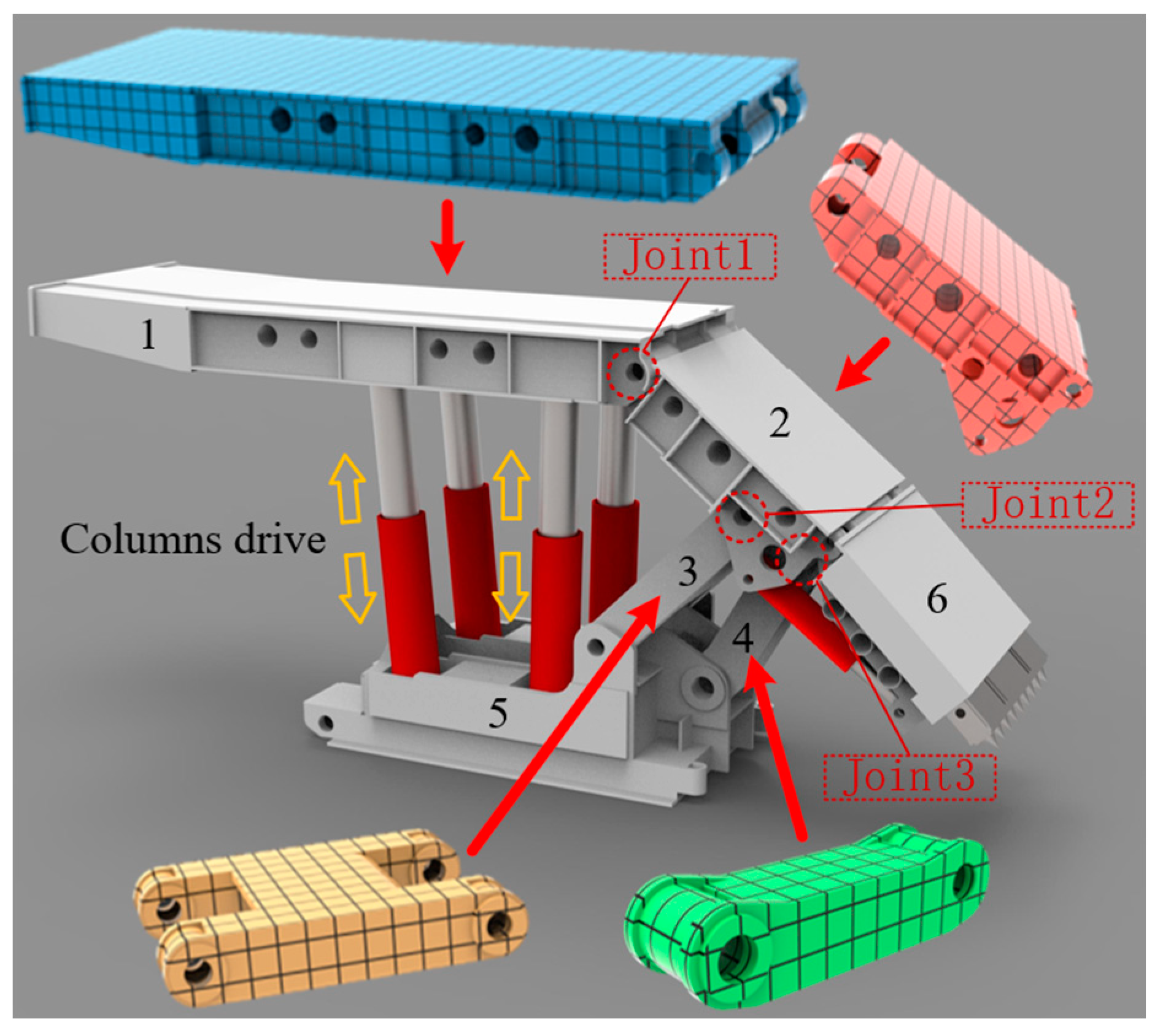
Figure 1 displays the caving coal hydraulic support by the top beam, shield beam, tail beam, base, and other parts, for the purposes of modifying the hydraulic support components’ response to be closer to the actual conditions, with the use of the Hypermesh pre-processing software package for hydraulic support flexibility. The material of support structure is defined as structural steel with density of 7860 kg/m3, Young’s modulus of 2.1 × 10¹¹ Pa, and Poisson’s ratio of 0.3, and the rigid node area set up at the hinge joint of the rotating pair is designed to enhance force transmission at the hinge point [36]. To facilitate the lifting support motion, additional column drives have been installed on the front and rear columns.
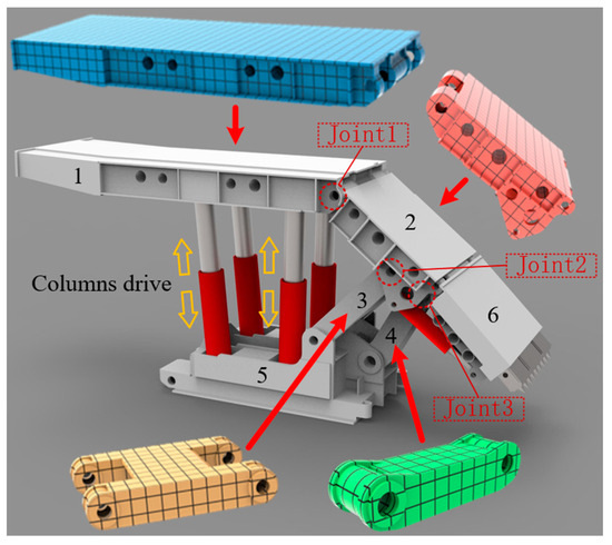
Figure 1.
Rigid–flexible coupling simulation model of hydraulic support. 1—top beam; 2—shield beam; 3—front connecting rod; 4—rear connecting rod; 5—base; 6—tail beam; Joint1—hinge point of top beam and shield beam; Joint2—shield beam and front-connecting rod hinge point; Joint3—shield beam and rear-connecting rod hinge point.
The simulation environment is as follows: ADAMS-2020 version is used for simulation, dynamic analysis type is default, dynamic integration solver is GSTIFF, dynamic integration format I3, dynamic allowable error is 0.001, kinematic allowable error is 0.0001, timestep is 0.001 s, optimization algorithm is MSCADS-MMFD, optimization tolerance is 0.001, optimization maximum iteration number is 100, optimization forward differentiation, Jacobi form integrator type is T:F:F:T: F:F:T:F, initial condition tolerance is 1 × 10⁻¹⁰, contact surface tolerance is 300, linear solver type is automatic, linear solver stability is 0.01.
2.1.2. Experiment of Hydraulic Support Lifting under Different Lifting Heights
To understand the influence of different lifting and lowering heights of support on its dynamic working characteristics, the front and rear columns are driven to descend by 30 mm, 45 mm, 60 mm, 75 mm, and 90 mm at a speed of 30 mm/s, and the support is lowered twice and lifted twice respectively. The hydraulic support starts at a height of 2500 mm, and the top outside of the top beam runs parallel to the bottom surface of the base.
2.1.3. Experiment of Hydraulic Support Lifting under Different Lifting Speeds
To investigate the impact of varying lifting and lowering speeds on the dynamic operational attributes of the support, the front and rear columns were operated to lower the support twice and subsequently lift it twice. This was performed at lifting speeds of 10 mm per second, 20 mm per second, 30 mm per second, 40 mm per second, and 50 mm per second, with a consistent single movement magnitude of 60 mm.
2.2. Dynamic Working Characteristics of Hydraulic Support Moving
2.2.1. Study on Microscopic Contact Theory between Hydraulic Support and Roof and Floor of Caving Face
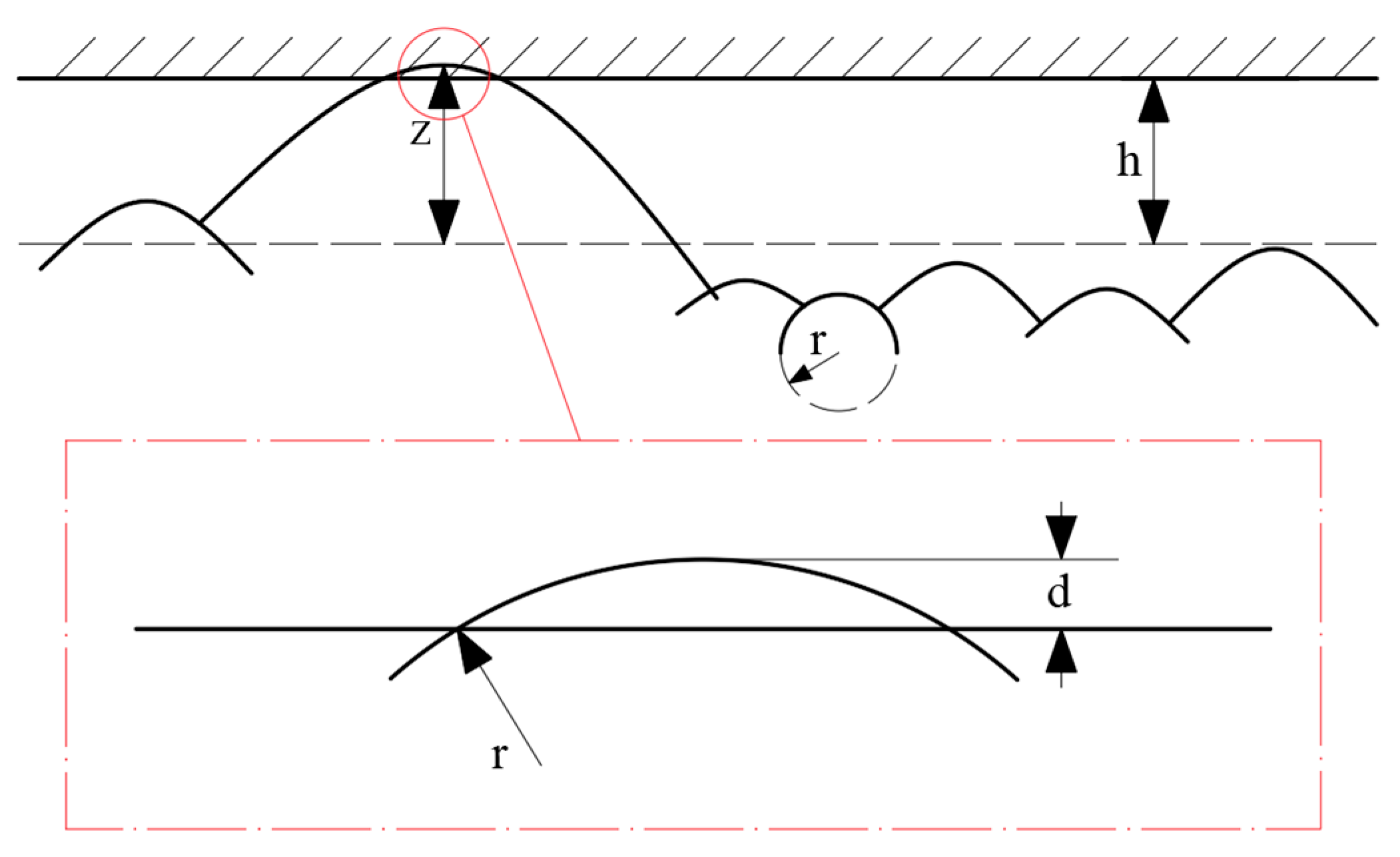
In the context of the caving face, when the support comes into interaction with the caving face, their interaction is modeled as a rigid surface meeting a rough surface based on the G-W theoretical model. Each micro-convex body on the surface is considered independent, without influencing one another, and all are treated as spherical micro-convex bodies with identical curvature radius [37]. The heights of the micro-convex bodies are distributed according to a Gaussian distribution. The contact model can be seen in Figure 2.
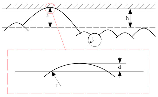
Figure 2.
Contact model of rough surface.
Under the assumption that the distance between two planes is denoted as h, and neglecting the elastic interaction between the micro-convex bodies, if the height of a micro-convex body is greater than h, it will be in contact with the rigid plane. The depth of indentation for a micro-convex body with height z can be calculated as d = z − h. Based on Hertzian contact theory, the contact behavior between these surfaces can be further analyzed:
Contact area of individual micro-convex body:
Force on individual micro-convex body:
Contact stiffness of individual micro-convex body:
According to Hertzian contact theory, the total number of micro-convex body in contact is
where: N represents the total number of micro-convex bodies, is a density function of contact area of micro-convex body, is the nominal contact area, is the dissemination function of height z of convex body satisfying Gaussian distribution, E is the modulus of elasticity of rough surface.
From Equations (1)–(4), by integrating over all micro-convex bodies, we obtain:
Total contact area
Total contact force
Total contact stiffness
2.2.2. Construction of Rigid–Flexible–Mechanical–Hydraulic Coupling Simulation Model of Hydraulic Support and Floor of Caving Face
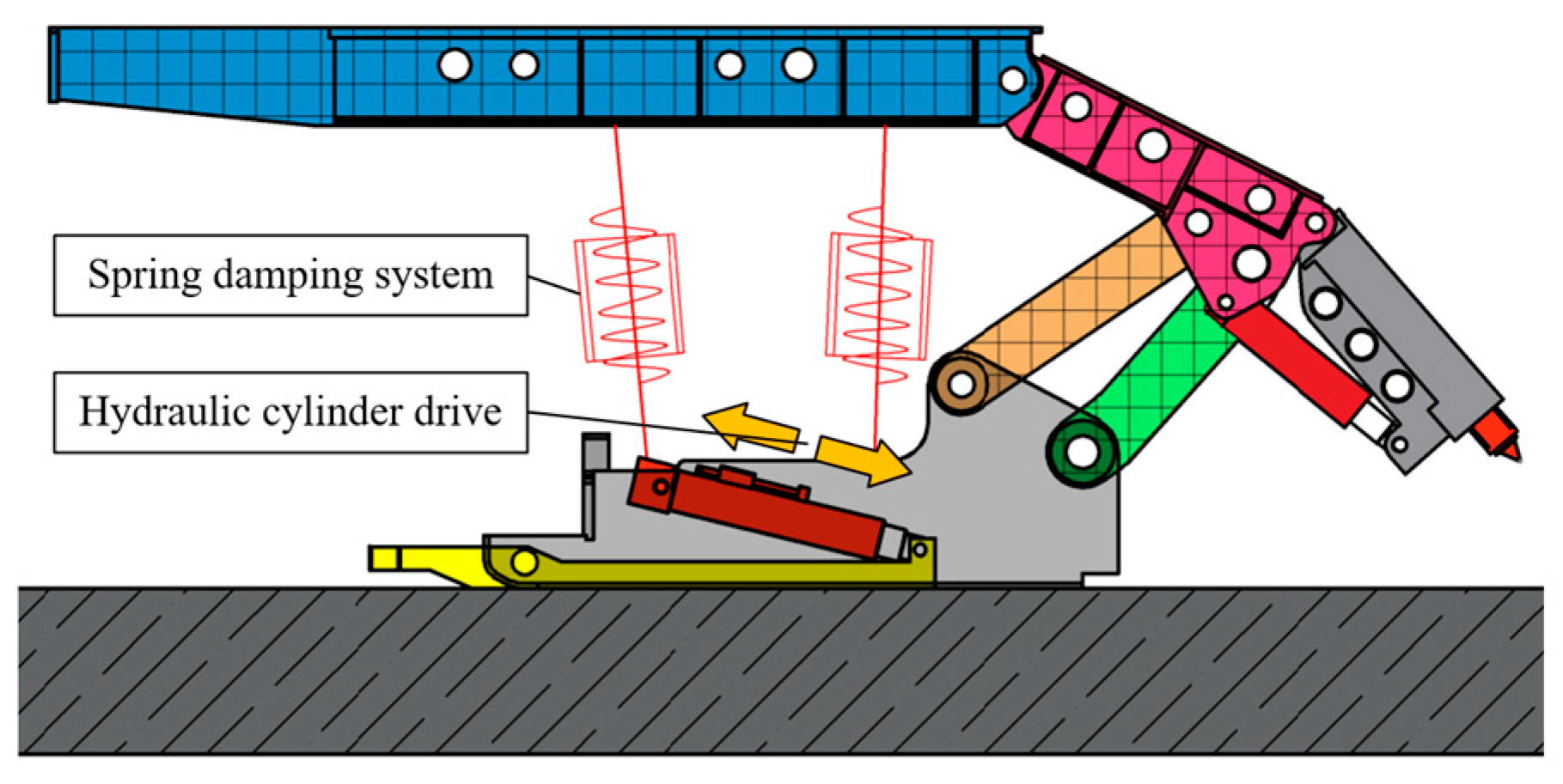
During the hydraulic support operation, the compression of the emulsion in the column cylinder leads to the manifestation of elastic properties as a result of applied force [38]. To enhance the rigid–flexible coupling dynamics simulation model of a hydraulic support depicted in Figure 1, the column is substituted with a spring damping system. Table 1 illustrates the structural attributes of the hydraulic cylinder and the physical properties of the emulsion.

Table 1.
Hydraulic cylinder attributes.
The total equivalent stiffness of the hydraulic cylinder can be obtained from Equation (8). Following this, the relationship between the equivalent stiffness of the hydraulic cylinder and the support height is established, completing the construction of the spring damping system. In Equation (8), the total equivalent stiffness of the hydraulic cylinder is the sum of the equivalent stiffness ka of the oil in the rodless cavity and the equivalent stiffness kb of the oil in the rod cavity, as shown below:
The equation variables are defined as follows: ka—equivalent stiffness of oil in rodless chamber; kb—equivalent stiffness of oil in rod chamber; A1—cross-sectional area of rodless chamber piston in cylinder; A2—cross-sectional area of rod chamber in cylinder; L—effective stroke of hydraulic cylinder; L1—current fluid level in cylinder rodless chamber; x—vibration displacement of system; V1—volume of oil in rodless chamber of hydraulic cylinder; V2—volume of fluid in cylinder rod chamber; Va—volume of oil in hydraulic line of rodless chamber in cylinder; Vb—the volume of fluid in a hydraulic line with a rod chamber in a hydraulic cylinder.
A cuboid entity is generated under the hydraulic support base as caving face floor, and the material is gangue, the density is 2800 kg/m3, the elastic modulus is 34 GPa, and the Poisson ratio is 0.3. Set the floor of caving face and hydraulic support base as collision contact, reasonably set the contact stiffness according to formula, complete the hydraulic support and caving face floor rigid–flexible–mechanical–hydraulic coupling simulation model construction [39,40], as shown in Figure 3, and realize the hydraulic support moving action by driving the pushing hydraulic cylinder.
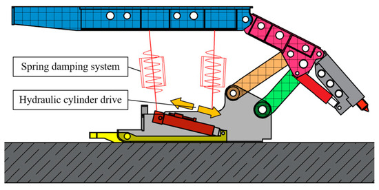
Figure 3.
Rigid–flexible–mechanical–hydraulic coupling simulation model of hydraulic support and caving face floor.
2.2.3. Experiment of Hydraulic Support Moving under Different Moving Speeds
In order to study the dynamic working characteristics of a hydraulic support at different moving speeds, the hydraulic support was moved at speeds of 100 mm per second, 200 mm per second, 300 mm per second, 400 mm per second, and 500 mm per second, respectively, at the working height of 2500 mm. In order to make the hydraulic support move from stable state, the hydraulic support was set to begin moving by the second, and the moving distance was 600 mm.
2.2.4. Experiment of Hydraulic Support Moving under Different Moving Heights
In order to study the dynamic working characteristics of a hydraulic support at different moving speeds, under the working height of 100 mm/s, the support was moved at the support heights of 2200 mm, 2300 mm, 2400 mm, 2500 mm and 2600 mm respectively. The moving action was set begin moving by the second, and the moving distance was 600 mm.
2.2.5. Experiment of Hydraulic Support Moving under Different Floor Conditions
When the hydraulic support is moving, the hydraulic support base contacts and rubs against the caving face floor, and there may be some floating coal that has not been cleaned up on the caving face floor. In order to explore the effect of the caving face floor conditions on the support movement, the caving face floor is divided into three categories: ① If the floating coal on the floor is cleaned thoroughly, the support will make contact with the floor gangue directly. ② If the floating coal on the floor is not cleaned thoroughly and some floating coal remains, the support will make contact with the coal gangue mixture, assuming that coal and gangue have the same influence on the contact conditions. ③ If there is a lot of floating coal on the floor, the support base is in direct contact with the coal. The material characteristics of coal, gangue, and support structure are shown in the table. According to the material characteristics shown in Table 2, contact stiffness for three types of contact conditions was calculated by the contact theory formula, and friction force parameters were displayed in Table 3.
Table 2.
Material parameters.
Table 3.
Friction parameters.
The support moving height of 2500 mm and the support moving speed of 100 mm/s are adopted to carry out the support moving simulation experiment, and the equivalent contact stiffness and friction coefficient under three kinds of floor contact conditions are adopted respectively.
2.3. Dynamic Working Characteristics of Hydraulic Support Moving with Pressure
For unstable or easily broken roof, roof instability may occur during the short working cycle of support lowering, moving, and lifting. The dynamic characteristics of support under varying working conditions are studied to investigate the effects of pressure on its performance.
2.3.1. Construction of Rigid–Flexible–Mechanical–Hydraulic Coupling Model of Hydraulic Support and Caving Face Roof and Floor
To investigate the dynamic operational characteristics of a hydraulic support during the process of pressure-induced support movement, a simulation roof is constructed above the top beam using a rigid–flexible–mechanical–hydraulic coupled simulation model of hydraulic support and caving face floor, as depicted in Figure 4. The material being simulated is coal [41]. A translational connection is established between the earth and the roof, with the translation track aligned with the force of gravity.
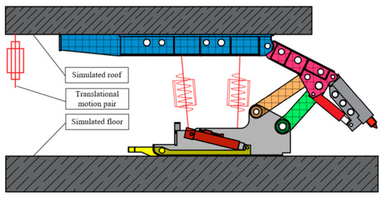
Figure 4.
Rigid–flexible–mechanical–hydraulic coupling simulation model of hydraulic support and caving face.
2.3.2. Experiment of Hydraulic Support Moving with Pressure under Different Heights
For the purpose of studying the influence of support moving height on support moving with pressure, support moving simulation experiments were carried out at support moving speed of 100 mm/s and residual working resistance of 500 kN at support moving heights of 2200 mm, 2300 mm, 2400 mm, 2500 mm and 2600 mm, respectively [42].
2.3.3. Experiment of Hydraulic Support Moving with Pressure under Different Speeds
For the purpose of studying the influence of support moving height on support moving with pressure, support moving simulation experiments were carried out at support moving height of 2500 mm and residual working resistance of 500 kN at support moving speeds of 100 mm per second, 200 mm per second, 300 mm per second, 400 mm per second, and 500 mm per second [43].
2.3.4. Experiment of Hydraulic Support Moving under Different Residual Working Resistance
In order to study and compare the influence of different load conditions on the working characteristics of a hydraulic support with pressure, under the conditions of support height of 2500 mm and speed of 100 mm/s, these experiments were carried out under different load conditions, with residual working resistances of 500 kN, 1000 kN, 1500 kN, 2000 kN, and 2500 kN, respectively.
2.3.5. Experiment of Hydraulic Support Moving with Pressure under Different Floor Conditions
With the aim of studying the effect of changed floor contact conditions on the work characteristics of a hydraulic support moving with pressure, simulation experiments were carried out with the equivalent contact stiffness and friction coefficient under three different floor contact conditions under the working conditions of residual working resistance of 500 kN at a moving height of 2500 mm and a moving speed of 100 mm/s.
2.3.6. Experiment of Hydraulic Support Moving with Pressure under Impact Load
In order to study that working characteristic of support under impact load, the support was driven to move with pressure under the working conditions of height 2500 mm, speed 100 mm/s, and working resistance 2500 kN, and the moving distance was 600 mm. Impact loads were applied 3 s after support transfer; impact loads were 250 kN, 500 kN, 750 kN, 1000 kN, 1250 kN, 1500 kN, 1750 kN, and 2000 kN, respectively; and impact time was 0.01 s.
3. Results
3.1. Results of Hydraulic Support Lifting Experiments
The angular acceleration of the hinge point of the four-bar linkage obtained from the simulation experiment of the lifting support is shown in Figure 5, and the response force diagram of the front column and the rear column is shown in Figure 6. Meanwhile, in order to describe the difference in dynamic response stability more clearly, the standard deviation is used to describe the fluctuation degree of response. In order to make the description of results more intuitive, the fluctuation coefficient FC is introduced to represent the standard deviation. The standard deviation calculation formula is shown in Equation (9).
where n is the total number of all data in the sample and u is the average of all data in the sample. The larger the fluctuation coefficient λ, the greater the degree of fluctuation in the stable response, indicating poorer stability. Conversely, the smaller fluctuation coefficient λ on behalf of the smaller response fluctuation degree, the better the stability.
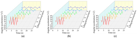
Figure 5.
Angular acceleration of hinge point of four-bar linkage in simulation under different lifting heights. (a) Joint1. (b) Joint2. (c) Joint3.
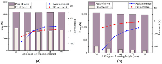
Figure 6.
Column response force in simulation under different lifting heights. (a) Front column. (b) Rear column.
According to Figure 5, with the height of the lifting support decreasing, it is noticeable that the peak value of each hinge point angular acceleration of the four-bar linkage displays a clear increase, and the fluctuation frequency is higher. When the height of lifting decreases from 45 mm to 30 mm, the angular acceleration changes most obviously.
According to the alterations in peak response force and fluctuation coefficient of the front column in Figure 6a, by increasing the height of the lifting support, it is noticeable that the peak response force and fluctuation coefficient of the front column exhibit a non-monotonic trend. Initially, they decrease, followed by an increase. When the lifting support height transitions from 30 mm to 60 mm, both the peak value of the front column response force and the fluctuation coefficient decrease, with the rate of decrease diminishing as the height increases. Subsequently, as the lifting support height changes from 60 mm to 90 mm, the peak value of the front column response force and the fluctuation coefficient start to rise, with the rate of increase intensifying as the height increases. According to the variation in peak response force and fluctuation coefficient of the rear column in Figure 6b, it can be found that with the increase in the height of the lifting support, the peak response force and fluctuation coefficient of the rear column present a monotonic decreasing trend, and the decreasing amplitude decreases with the increase in height.
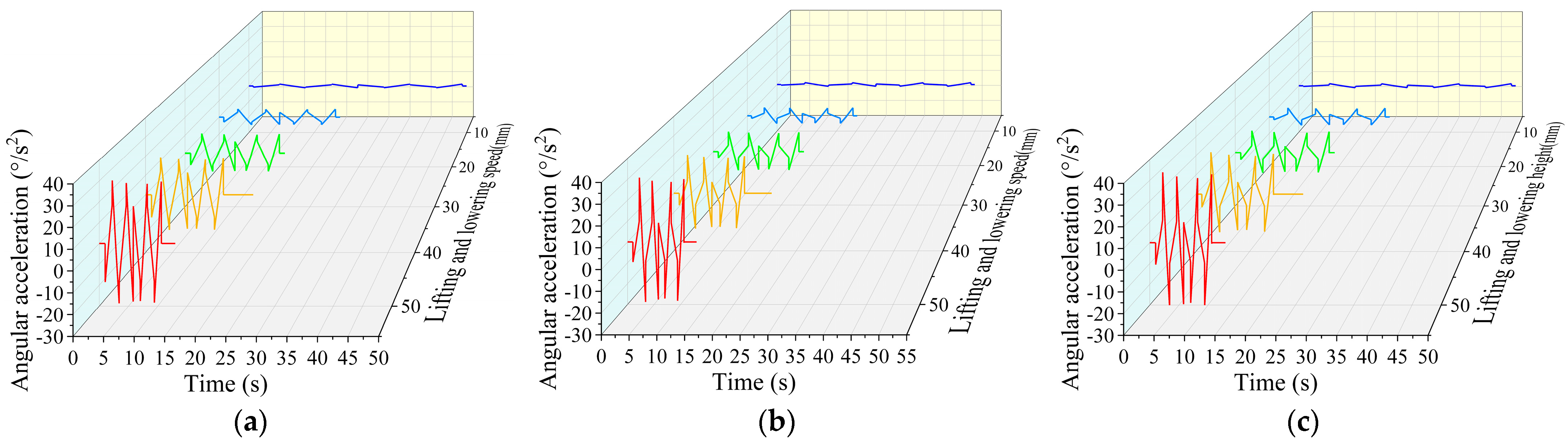
Through the experiment of a hydraulic support lifting under different speeds, the hinge point angular acceleration of the four-bar linkage is depicted in Figure 7, while the response force of both the front and rear columns can be observed in Figure 8.
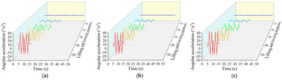
Figure 7.
Angular acceleration of hinge point of four-bar linkage in simulation under different lifting speeds. (a) Joint1. (b) Joint2. (c) Joint3.

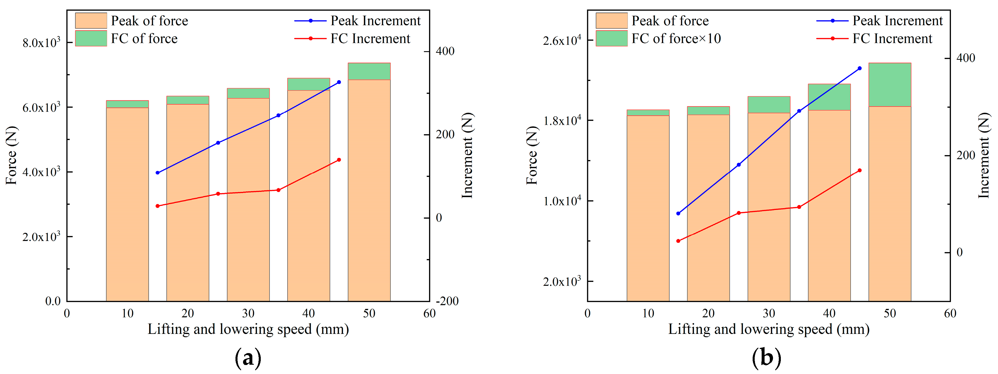
Figure 8.
Column response force in simulation under different lifting speeds. (a) Front column. (b) Rear column.
According to Figure 7, with the speed of the lifting support increasing, each hinge point’s angular acceleration peak of the four-bar linkage significantly increases, and the fluctuation frequency is higher.
According to Figure 8a,b, the front and rear columns response forces exhibit similar trends, with the rear column demonstrating significantly higher response forces compared to the front column. The peak response force and wave coefficient in the front column escalates with the lifting support speed, showing a linear increase in amplitude with the speed.
The analysis results indicate that an increase in lifting speed will notably affect the stability of the hydraulic support four-bar linkage, the load stability of the front and rear columns, and the peak response force. Moreover, this impact becomes more pronounced at higher speeds.
3.2. Results of Hydraulic Support Moving Experiments
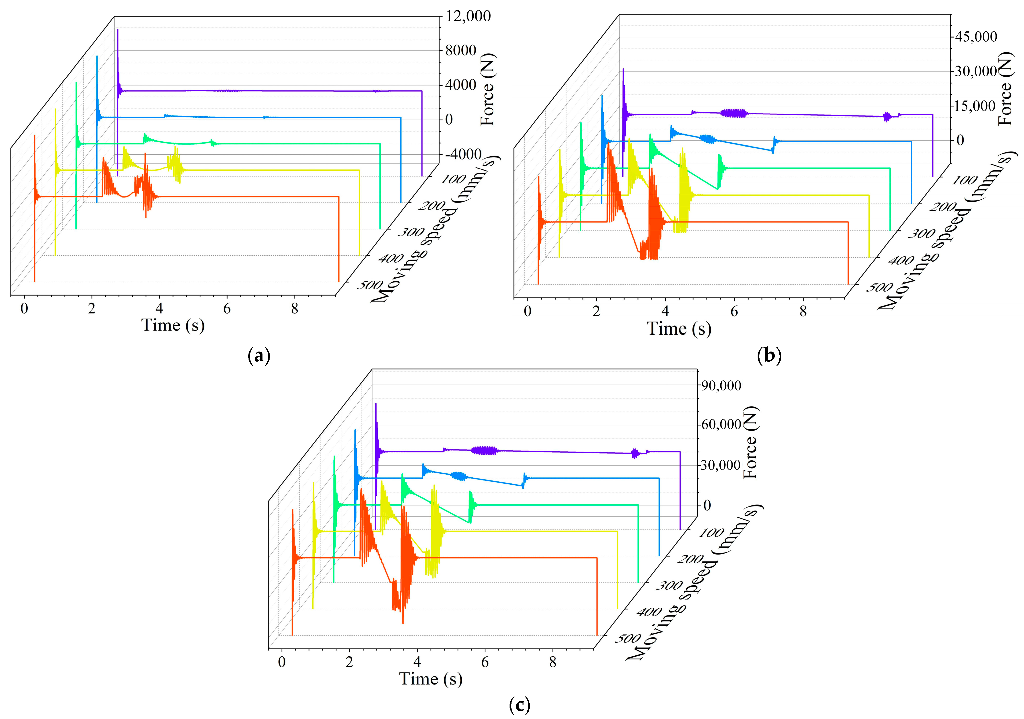
Through simulation experiments of a hydraulic support moving under different speeds, the forces of each hinge point of the four-bar linkage and columns of a hydraulic support are obtained as shown in Figure 9 and Figure 10, and the acceleration of top beam is shown in Figure 11.
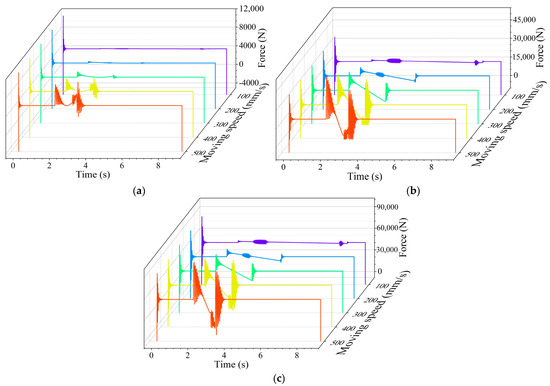
Figure 9.
Response force of hinge point of four-bar linkage in simulation under different moving speeds. (a) Joint1. (b) Joint2. (c) Joint3.
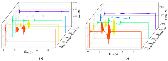
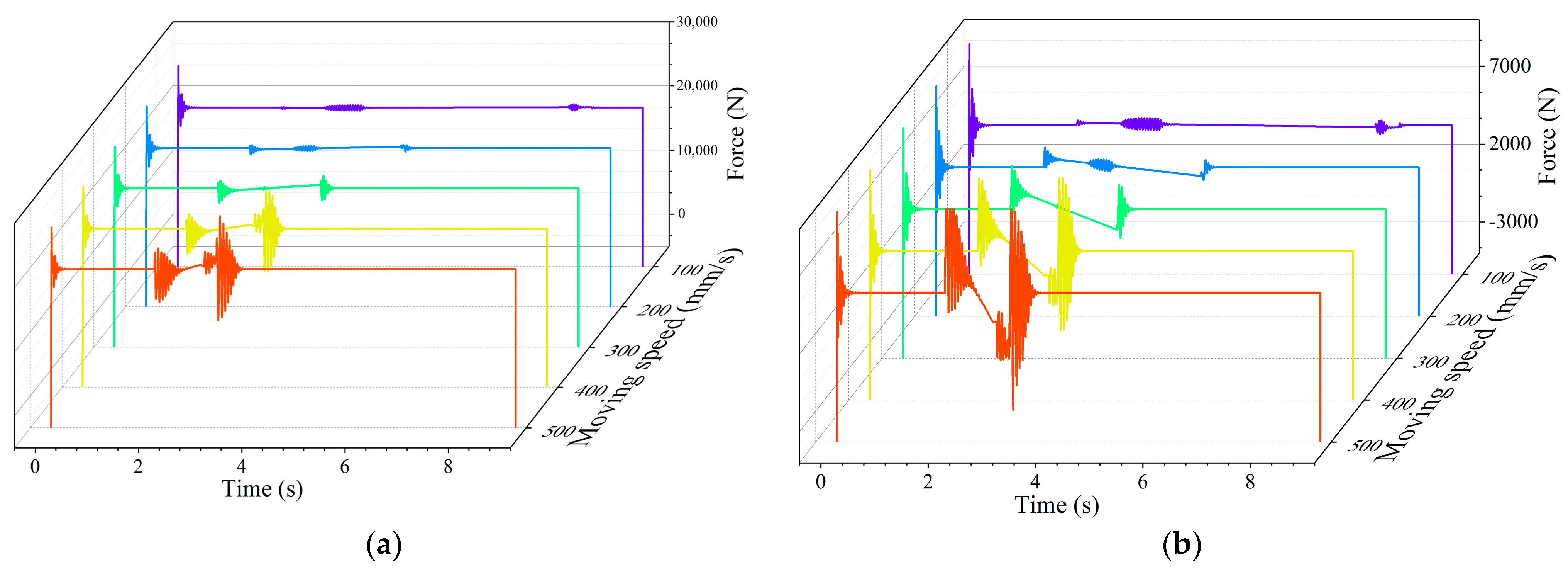
Figure 10.
Column response force in simulation under different moving speeds. (a) Front column. (b) Rear column.

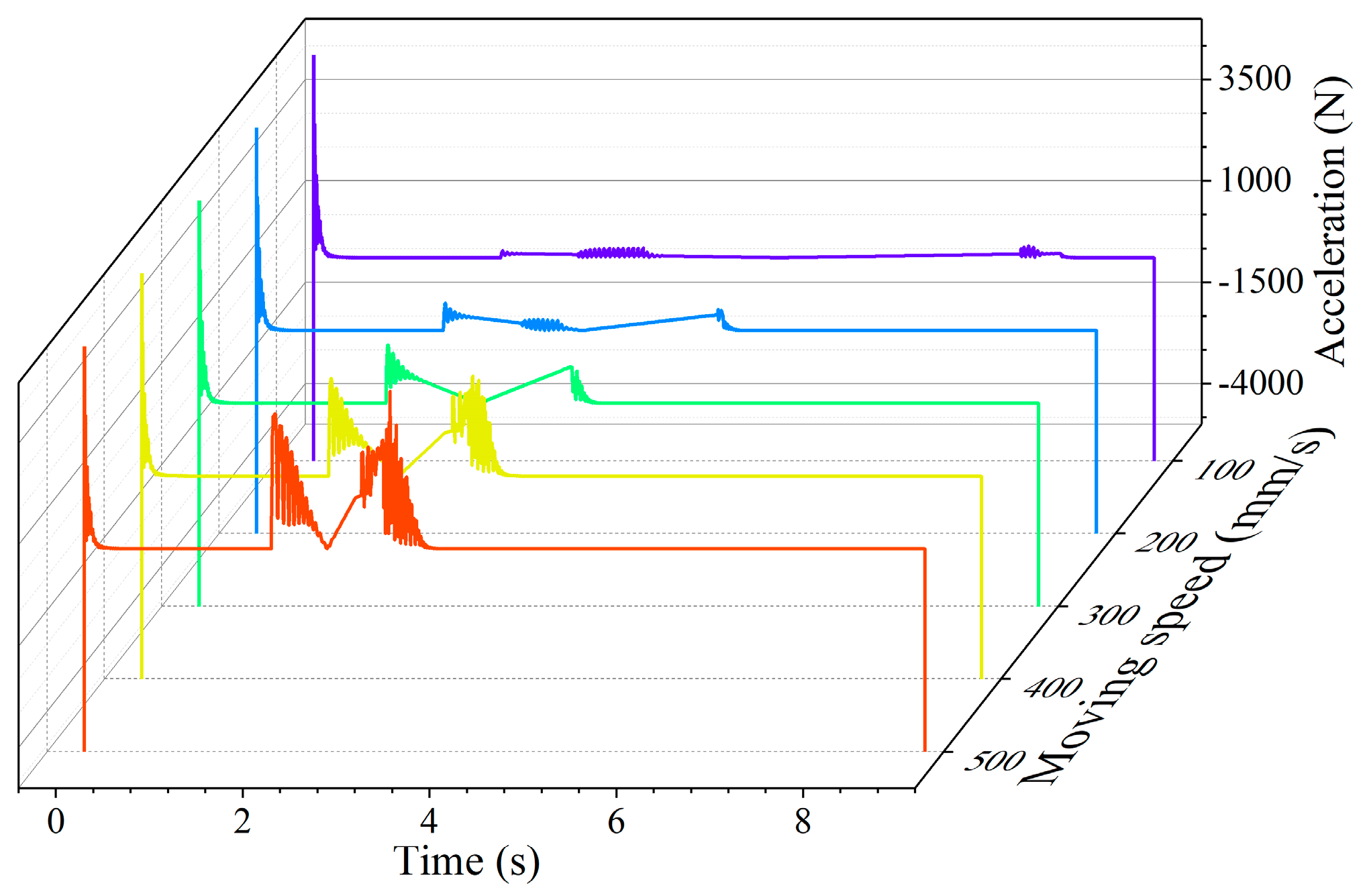
Figure 11.
Acceleration of top beam in simulation under different moving speeds.
Figure 9 shows the force variation in each hinge point in four-bar linkage of the support with the change under moving speed. It is apparent from the curve in the figure that as the support moving speed increases, the peak force value at each hinge point shows a significant rise, along with a notable increase in the fluctuation range. At the beginning of simulation, the hinge force fluctuates obviously at every speed, and then stabilizes rapidly, which is caused by the first contact between the hydraulic support base and the caving face floor, which produces a large contact force. This process is the change stage from unbalanced state to stable state of the support. At the beginning and end of the moving support, the force at each hinge point increases obviously, and stabilizes after fluctuation.
The response force of Joint1 changes slightly at low speeds of 100 mm/s and 200 mm/s, and the response force decreases first and then increases during support moving.
In the process of the support moving, the response forces at Joint2 and Joint3 demonstrate a consistent decline trend, and unstable fluctuations occur in the joint force at the low speed of 100 mm/s and 200 mm/s.
It can be seen from Figure 10 that the peak response force and fluctuation range in the front and rear columns increase significantly when the moving speed increases. The response force in column fluctuates significantly at the beginning of simulation and at the beginning and end of the support moving. Unstable fluctuations of column response force occurs in the procedure of the support moving at low speed of 100 mm/s and 200 mm/s. In the procedure of the support moving, the response force in the front column increases while the force in the rear column decreases.
The acceleration curve of the top beam under different moving speeds is shown in Figure 11. When moving speed increases, the peak value and fluctuation range of top beam acceleration obviously increase. The acceleration of the top beam fluctuates obviously at the beginning of the simulation and at the beginning and end of the support movement. The response force in the column exhibits unstable fluctuations while transferring the support at both 100 mm/s and 200 mm/s low-speed conditions. During the support transfer beyond 100 mm/s, the acceleration of the top beam initially decreases and then increases. However, the change trend is not clearly evident when transferring the support at the low speed of 100 mm/s.
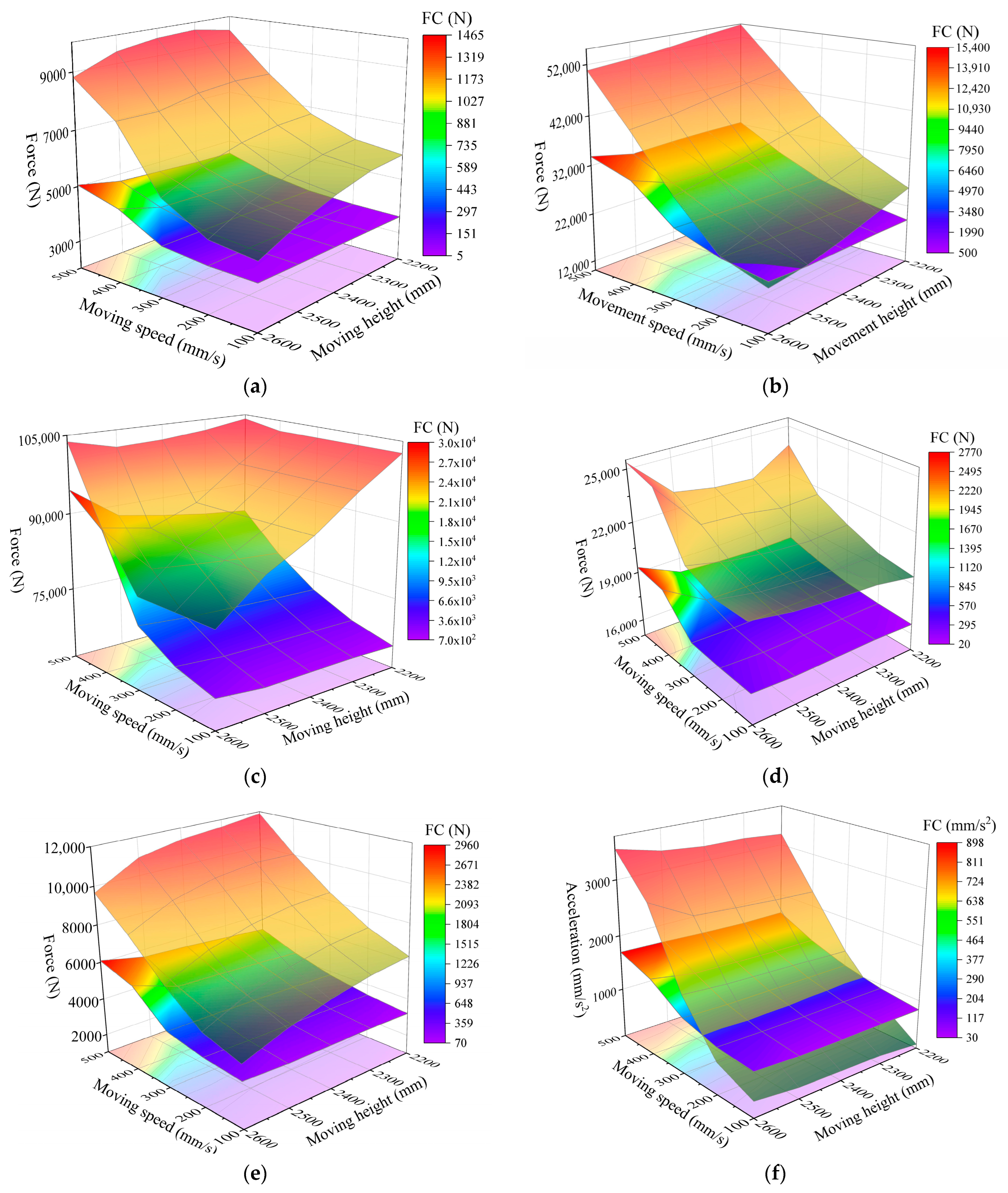
When the simulation of the support moving without pressure under each height and speed in sequence was completed, we obtained the reaction force at each pivot point, the reaction force at the column, and the acceleration of the top beam in the hydraulic support quadrilateral linkage. Because the change trend was not obvious enough from the time domain curve, in order to obtain the change characteristics accurately, we took the peak value and fluctuation coefficient of each group of data. The upper surface of the figure is the peak value. A scale is provided on the right side of the figure. The middle surface is the wave coefficient, using the Z axis scale. Since the middle surface is partially obscured by the upper surface, the color of the middle surface is mapped on the lower surface to assist in characterizing the wave coefficient. Figure 12 shows the characteristics of the hinge point response force, column response force, and top beam acceleration of the hydraulic support four-bar linkage under different support moving speeds and heights.

Figure 12.
Response of hydraulic support in simulation under different moving speeds and moving heights. (a) Response force of Joint1. (b) Response force of Joint2. (c) Response force of Joint3. (d) Response force of front column. (e) Response force of rear column. (f) Acceleration of top beam.
Figure 12a–c show the force response characteristics of each hinge point of the hydraulic support four-bar linkage at different moving heights and speeds. From the diagram, it is evident that the stress variation patterns of every hinge point in the four-bar linkage remain largely consistent. As the height of the moving support increase, the fluctuation coefficient of the hinge point force increases, while the peak value decreases. Similarly, as the speed of movement increases, both the peak response force and the fluctuation coefficient of each hinge point experience an increase. The height of the moving support significantly influences the peak response force of the hinge point when the support moves at a low speed, whereas its influence becomes marginal at high speeds. When the moving speed is 500 mm/s, the peak response force of Joint1 and Joint3 increases first and then decreases, and decreases first and then increases, with the increasing of moving height, but the change in amplitude is not large. When the height of the moving support is small, the speed of the moving support has a significant impact on the peak response force of the hinge point. However, when the height of the moving support is large, the peak response force of the hinge point becomes even more sensitive to changes in the speed of the moving support. On the contrary, the fluctuation coefficient of the hinge point is more sensitive to the height of the moving support when moving the support at high speed, and the fluctuation coefficient of the hinge point response force is more sensitive to the speed of the moving support when moving the support at a low position.
The column response force characteristics are shown in Figure 12d,e. The variation trend of the response force fluctuation coefficient of the front and rear columns is basically the same. With the increase in the support moving speed, the column response force fluctuation coefficient increases. The support moving height has a greater influence on the column response force peak value at low speed, while the influence is smaller at high speeds. The peak value of the column response force is more responsive to changes in the support movement height at low speeds. The fluctuation coefficient of the column force tends to increase with the support movement height, showing a greater sensitivity to height changes at high speeds and to speed changes at lower positions. With an increase in the support movement speed, the peak value of the front column response force rises, remaining relatively constant within the 100–300 mm/s range of the support movement heights. Within the 400–500 mm/s range, the movement speed initially decreases and then increases with the rising movement height. Conversely, the peak response force of the rear column decreases with the support movement height but increases with the movement speed.
The acceleration characteristics of the top beam during the support moving process are shown in Figure 12f. The peak acceleration and fluctuation coefficient of the top beam reach their maximum values at the height of 2600 mm and the moving speed of 500 mm/s. The peak value and fluctuation coefficient of the top beam acceleration increase with the speed of the moving support, and the peak value of the top beam acceleration increases with the height of the moving support, but the amplitude is less than that in line with the speed of the moving support. When the height of the moving support changes, the peak value and fluctuation coefficient of top beam acceleration are relatively stable, which proves that the acceleration response of the top beam is more sensitive to the speed of the moving support.
Through the simulation experiment of the hydraulic support moving under different floor conditions, the response parameters of the hydraulic support are obtained as shown in Figure 13.

Figure 13.
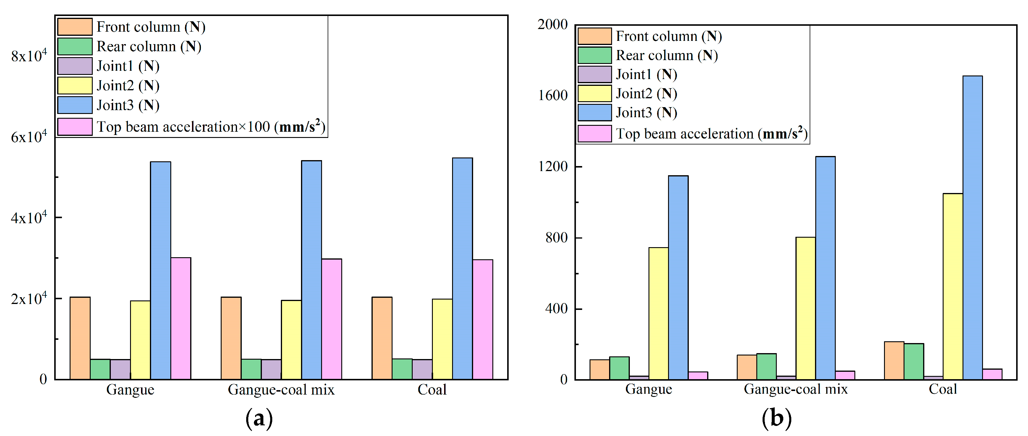
Response of hydraulic support in simulation under different floor contact conditions. (a) Peak. (b) Fluctuation coefficient.
According to the examination of the hydraulic support response results in Figure 13, it can be inferred that the peak value of the hydraulic support response has no obvious change under different floor contact conditions, while the response fluctuation coefficient is minimal under pure gangue floor contact conditions, and maximal under pure coal floor contact conditions, and the value under mixed coal gangue contact conditions is between the two. This indicates that with the increase in floating coal in floor, the response fluctuation in the hydraulic support moving is greater.
3.3. Results of Hydraulic Support Moving with Pressure Experiments
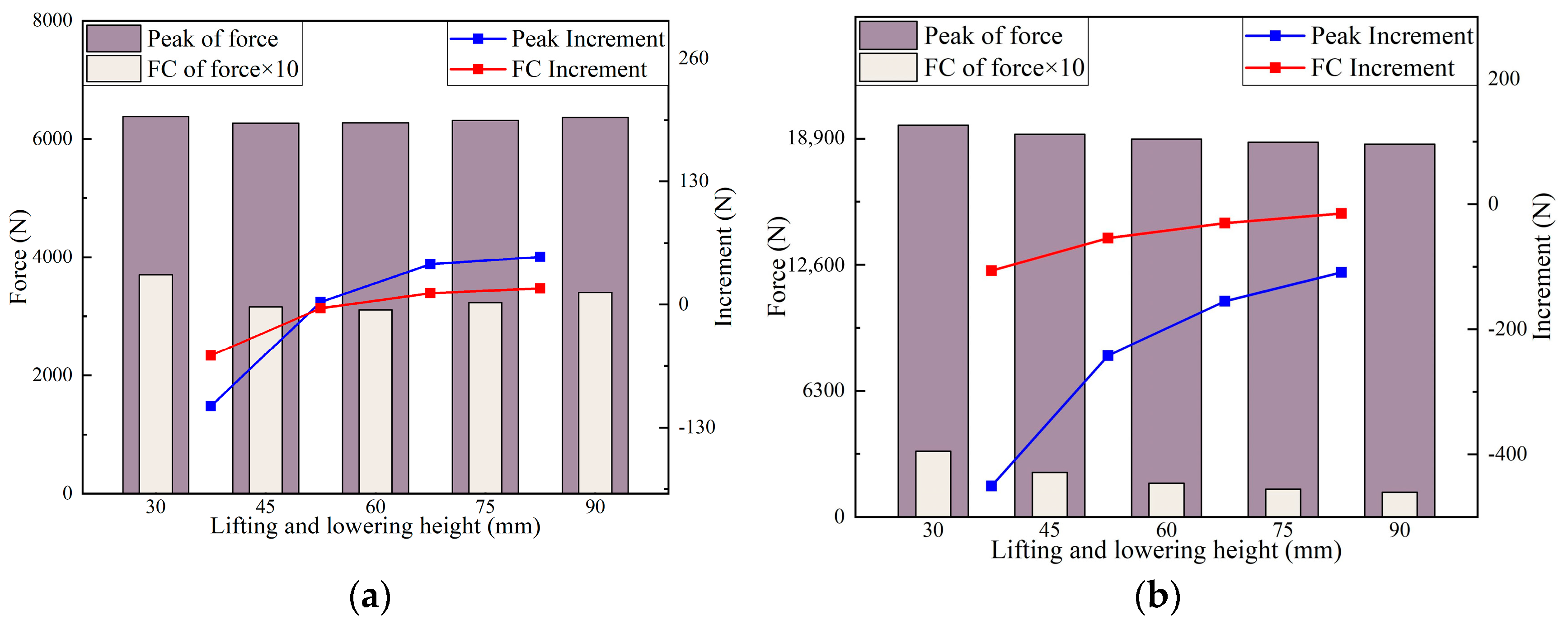
Through the simulation experiment of a hydraulic support moving with pressure under different height, various response parameters of the hydraulic support were obtained as shown in Figure 14.
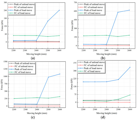
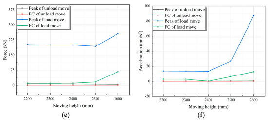
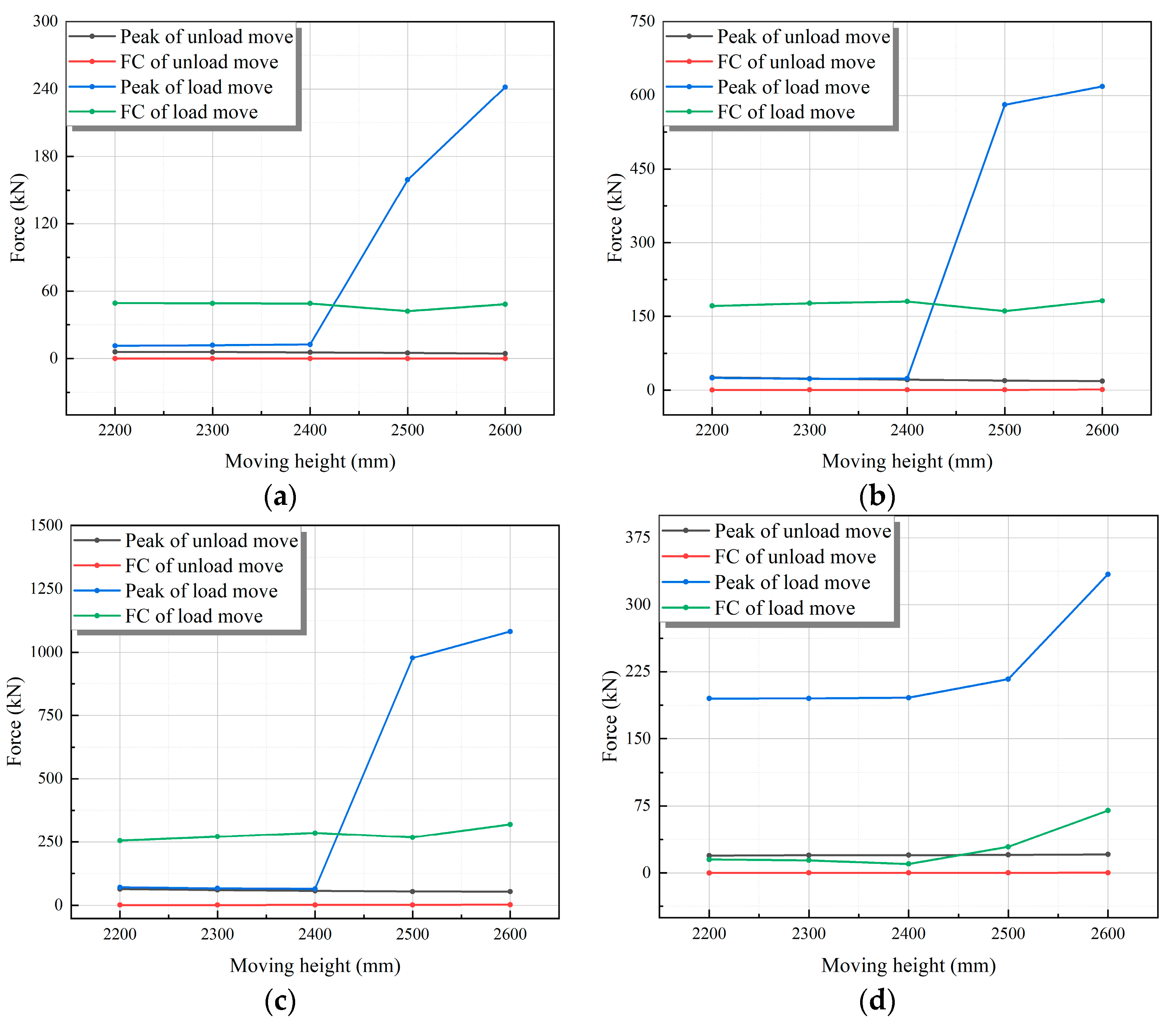
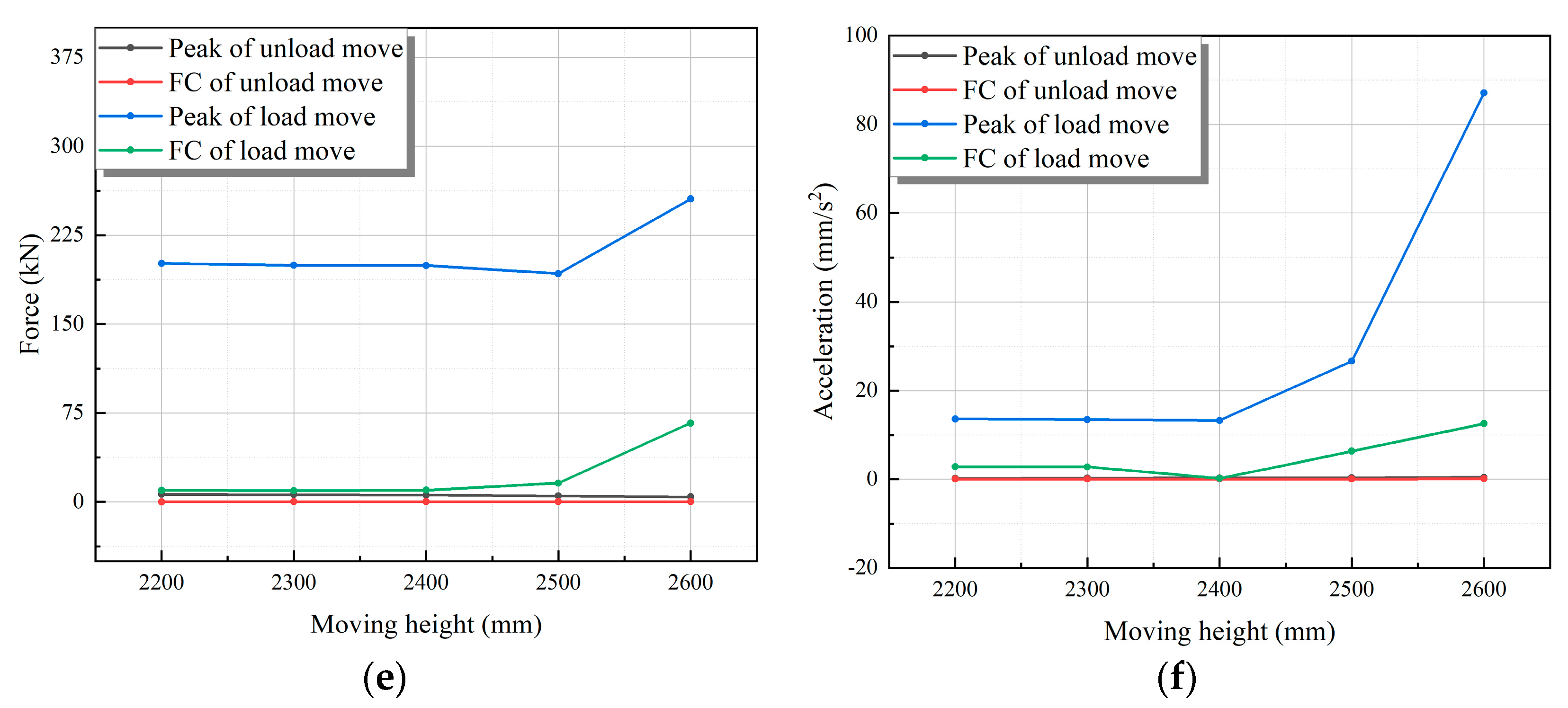
Figure 14.
Response of hydraulic support moving with and without pressure in simulation under different heights. (a) Response force of Joint1. (b) Response force of Joint2. (c) Response force of Joint3. (d) Response force of front column. (e) Response force of rear column. (f) Acceleration of top beam.
The response comparison between the support with pressure and without pressure under different moving speed is shown in Figure 14. The change trend is basically the same. The peak response force and fluctuation coefficient of the hydraulic support with pressure are greater than those of the hydraulic support without pressure. With the increase in moving height, the overall trend is increasing. The peak response force and the fluctuation coefficient change smoothly when the moving height increases from 2200 mm to 2400 mm, but increase significantly when the moving height increases from 2400 mm to 2600 mm.
Through the simulation experiment of the hydraulic support moving with pressure under different moving speeds, the response parameters of the hydraulic support were obtained as shown in Figure 15.
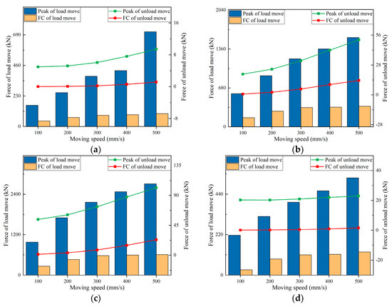
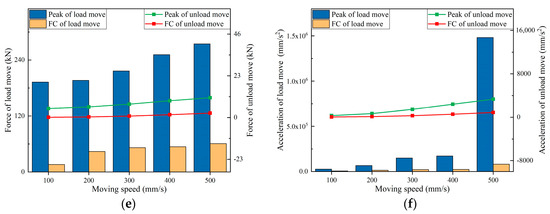
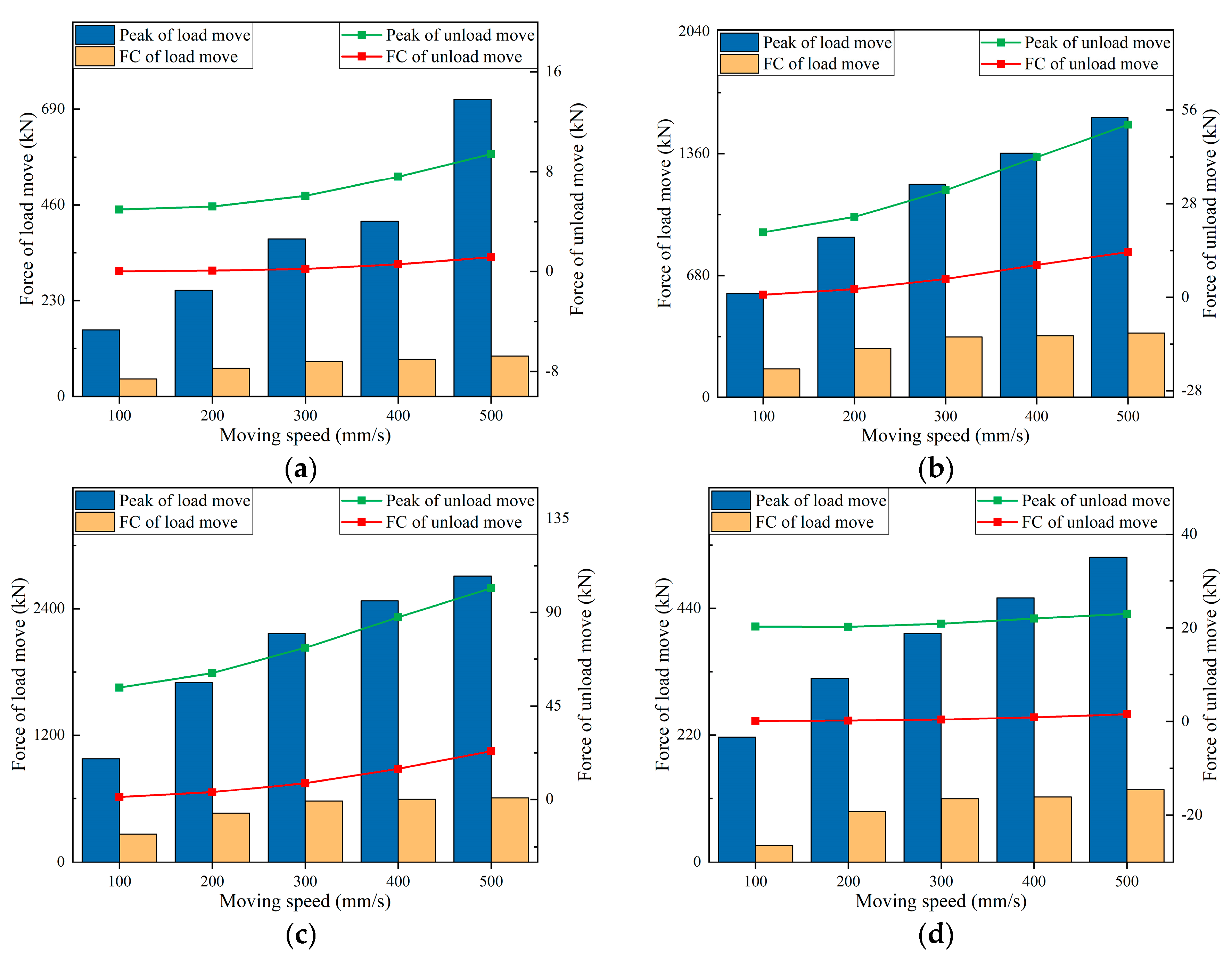
Figure 15.
Response of hydraulic support moving with and without pressure in simulation under different speeds. (a) Response force of Joint1. (b) Response force of Joint2. (c) Response force of Joint3. (d) Response force of front column. (e) Response force of rear column. (f) Acceleration of top beam.
The response comparison between the support with pressure and without pressure under different support moving speeds is shown in Figure 15, and its variation trend is basically the same. The peak response force and fluctuation coefficient when moving with pressure are greater than those when moving without pressure, and both show an increasing trend with the rise in moving speed. As the speed increases from 400 mm/s to 500 mm/s, the response force at Joint1 hinge point and the acceleration of the top beam show a notable increase.
Through the experiments of a hydraulic support moving with pressure under different residual working resistance, the response characteristics of the hydraulic support were obtained as shown in Figure 16.
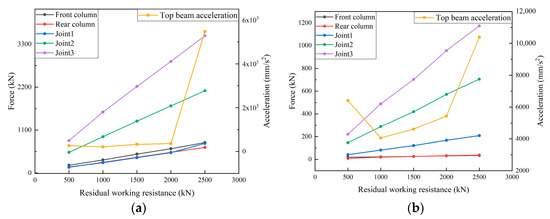
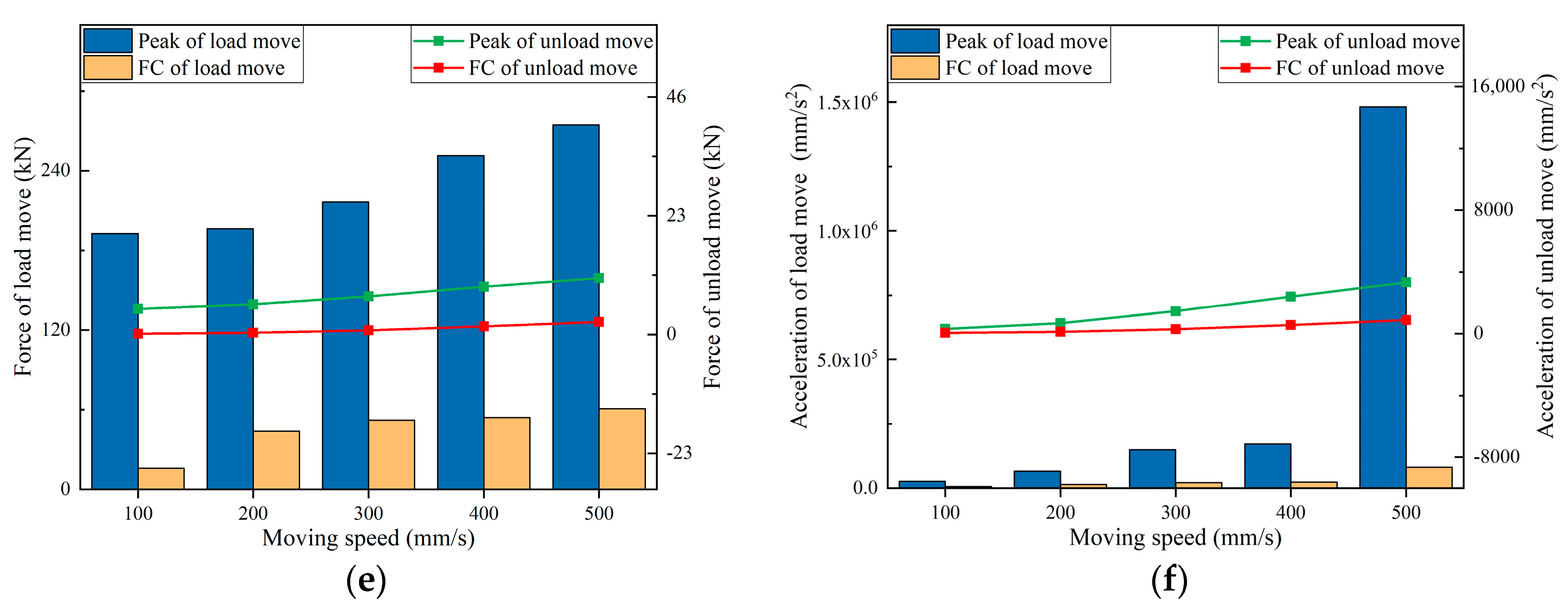
Figure 16.
Response of hydraulic support in simulation under different residual working resistance. (a) Peak. (b) Fluctuation coefficient.
From Figure 16, it is evident that as the residual working resistance increases, the peak value and fluctuation coefficient of the response force at the hinge point of the four-bar linkage clearly increase. Furthermore, the peak value of the response force in the front and rear columns shows a significant increase, while its fluctuation coefficient exhibits no obvious change. The peak acceleration of top beam changes smoothly when the working resistance is 500–2000 kN, and increases greatly when the residual working resistance increases from 2000 kN to 2500 kN. The fluctuation coefficient of top beam acceleration diminishes first and then rises with the grow of working resistance, the minimum value appears at the working resistance of 1000 kN, and the maximum value appears at 2500 kN. The analysis results show that residual working resistance has a significant effect on the stability of the support moving with pressure, and proper residual working resistance should be carefully selected.
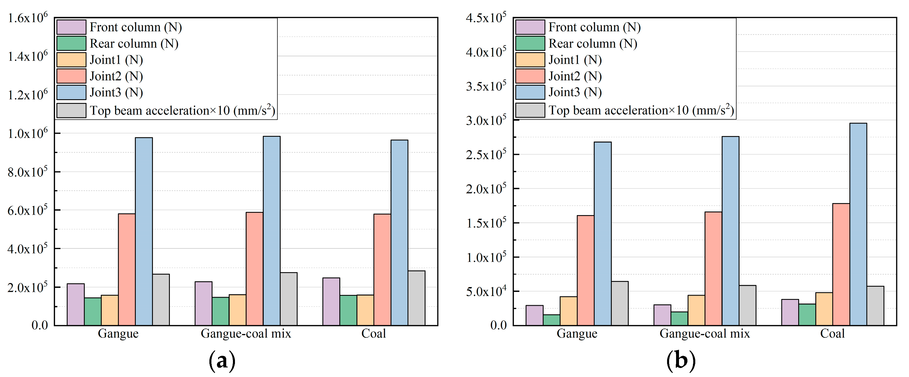
Through the simulation experiments of the hydraulic support moving with pressure under different contact conditions of floor, the response parameters of the support were obtained as shown in Figure 17.
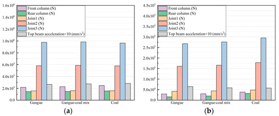
Figure 17.
Response of hydraulic support moving with pressure in simulation under different floor conditions. (a) Peak. (b) Fluctuation coefficient.
It can be seen from Figure 17 that the peak value of the hydraulic support response moving with pressure has no obvious change under different floor contact conditions, while the response fluctuation coefficient is the smallest under pure gangue floor contact conditions, and the largest under pure coal floor contact conditions, and the value under mixed coal gangue contact conditions is between the two. This indicates that the response fluctuation of the hydraulic support moving with pressure becomes larger with the increase in floating coal in floor.
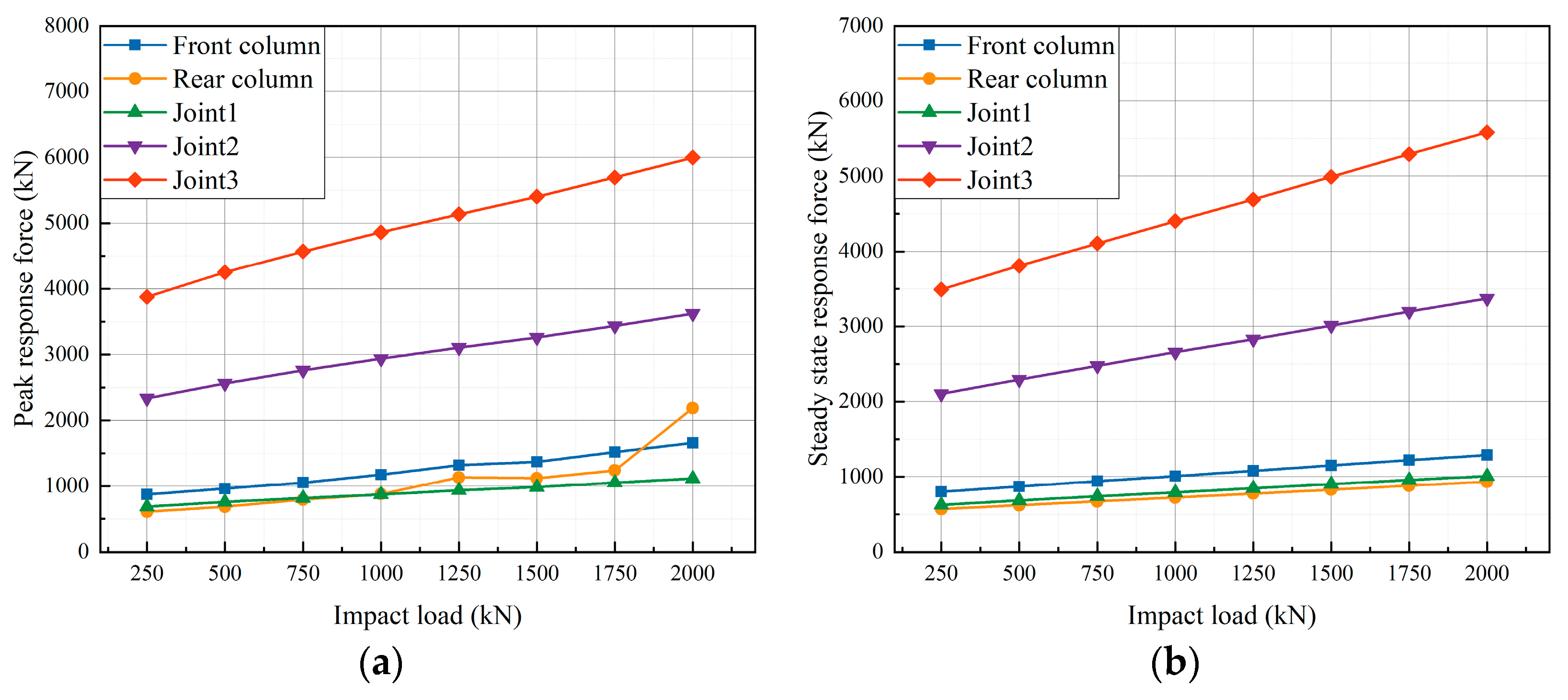
Through the simulation experiment of the hydraulic support moving with pressure under the impact load, resulting in the impact response of the support depicted in Figure 18.
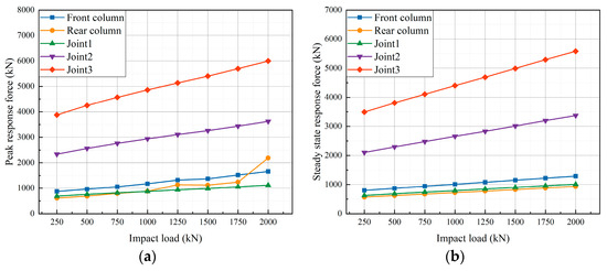
Figure 18.
Response of hydraulic support moving with pressure in simulation under different impact loads. (a) Peak. (b) Fluctuation coefficient.
In Figure 18, the peak response force and steady-state response force resulting from various impact loads during the movement of the hydraulic support with pressure are illustrated. The analysis indicates that both the peak response force and steady-state response force at the hinge point of the hydraulic support four-bar linkage increase linearly with the rise in the impact load. Similarly, the steady-state response force in the front and rear columns also exhibits a linear increase with the impact load. The peak response force demonstrates an increasing trend with noticeable fluctuations. Specifically, as the impact load increases from 1750 kN to 2000 kN, the peak response force experiences a substantial increase of 948.05 kN. These findings highlight the significant effect of the impact load on the stability of the support, with stability notably decreasing under higher impact loads.
4. Discussion
The analysis of the response of hydraulic support columns under an impact load in reference [14] is based on the ADAMS software package 2020, and the support components are treated with flexibility. Both this study and reference [14] used contact stiffness and penetration depth to calculate the contact force between the coal mining face and the support. Reference [14] does not explain how to calculate the contact stiffness. However, this study is based on the G-W contact theory and a micro dynamic theoretical model of the contact between the hydraulic support and the roof and floor of the caving face. For the first time, an accurate contact stiffness is obtained through theoretical derivation. Complex contact forces are generated by the contact between the hydraulic support and the roof and floor of the caving face instead of static loading to analyze the hydraulic support. Moreover, both this article and reference [14] treat the column as an equivalent spring damping system, but this article provides detailed calculations of the spring stiffness to further modify the simulation to be closer to actual working conditions.
Both this study and reference [14] studied the stability of hydraulic supports by analyzing the response force between the components and the hinge points of the hydraulic support. However, reference [14] only studied the hydraulic support under static load conditions, while this study considered the dynamic process of the hydraulic support and conducted in-depth research on various components with larger responses, obtaining comprehensive response parameters of the hydraulic support.
This study is based on the G-W contact theory and a micro dynamic theoretical model of the contact between the hydraulic support and the roof and floor of the caving face. For the first time, accurate surface contact stiffness is obtained through theoretical derivation. The complex contact force generated by the contact between the hydraulic support and the roof and floor of the caving face is used to analyze the hydraulic support instead of static loading. Reference [44] applied the Hertz theory to derive the contact force and contact stiffness of a rigid body in contact with a random elastic rough surface. The obtained expression is basically consistent with the results derived in this study. The direct derivation results in reference [44] are consistent with the three-dimensional simulation experimental results of rough surface contact in reference [45].
In summary, compared with reference [14], in a response analysis of a hydraulic support, this study establishes a micro-dynamic model based on G-W contact theory to accurately calculate the surface contact stiffness and calculate the equivalent spring stiffness of a hydraulic column in detail, so that the simulation is closer to the actual working conditions. Moreover, this study considers the dynamic processes and responses of multiple components more comprehensively than reference [14]. In addition, the theoretical derivation results of this study are basically consistent with the Hertz theoretical derivation results in reference [44], and are consistent with the experimental verification in reference [45], further ensuring the reliability of the study. The above comparison indicates that the model construction method, research method, and simulation parameter setting based on the theoretical research in this study have a scientific basis, and the results obtained are also reliable.
5. Conclusions
Based on the G-W contact theory, the paper innovatively puts forward a microcontact dynamic model of a hydraulic support and the caving face roof and floor, establishes a rigid–flexible–mechanical–hydraulic coupling dynamic simulation model of a hydraulic support and the caving face roof and floor, and obtains the following conclusions through a simulation analysis of lifting, lowering, and moving under various conditions:
- (1)
- With the increase in the height of the support lifting, the peak angular acceleration of the hinge point of the four-bar linkage decreases, and the fluctuation frequency decreases; the response force of the front column decreases first and then increases, and the rear column decreases. The peak value and fluctuation of angular acceleration at the hinge point of the four-bar linkage increase with the increase in the speed of the lifting; the response force trend of the front and rear pillars is similar, but the rear pillar is obviously higher than the front pillar. In practical application, the relationship between the speed of the lifting and the stability of the system should be balanced, and the state of the rear column should be mainly detected. Hydraulic supports need to be designed with the height and speed of the lifting in mind to ensure that the support maintains stability and safety under various operating conditions.
- (2)
- The response of the hydraulic support is affected by different contact conditions of the floor, and the increase in floating coal on the floor will lead to a greater fluctuation in the response when moving the support. In actual fully mechanized coal mining, it is necessary to consider the influence of different floor conditions on the support stability, and it may be necessary to adjust the working parameters of the support to strengthen the adaptability to different floors.
- (3)
- The peak value and fluctuation of response stress are larger when the support is moving with pressure than when moving without pressure, and increase with the height and speed of the moving. This shows that the response of the structure will increase significantly due to the influence of an extra load when the hydraulic support is moving with pressure. When selecting the mode of the support moving with pressure, the working conditions should be carefully analyzed, and the speed and height should be controlled.
- (4)
- With the increase in the moving support height, the fluctuation of the hinge point force increases and the peak value decreases, and with the increase in the support moving speed, the peak value and fluctuation of the hinge point force increase. Under different height and speed conditions, the sensitivity of the response to the change in height or speed of the moving support is different. The height and speed of the moving support will affect the response of the hydraulic support structure obviously, so it is necessary to choose an appropriate height and speed of the support moving according to working conditions.
- (5)
- The increase in residual working resistance will lead to the increase in the response of the four-bar linkage and column, which will affect the stability of the support moving. The residual working resistance should be carefully selected.
- (6)
- When subjected to the impact load during the support moving, the response force of the four-bar linkage and column increases linearly and fluctuates obviously when the support is impacted. When designing hydraulic supports, it is necessary to consider the possible impact loads and take measures to enhance the impact resistance of hydraulic supports to ensure that they can maintain stability and safety when subjected to the impact load.
The research in this paper provides a theoretical model and accurate simulation parameter setting method for the simulation research of surface contact between objects, provides an accurate rigid–flexible–mechanical–hydraulic coupling simulation model for the hydraulic support moving, provides a theoretical basis for the hydraulic support moving mode selection, and provides technical guidance for the hydraulic support design and optimization.
The main advantage of this research method lies in putting forward a micro-dynamic model of a hydraulic support and the caving face roof and floor based on G-W contact theory, establishing a rigid–flexible–mechanical–hydraulic coupling dynamic simulation model of a hydraulic support and the roof and floor of the caving face, and revealing the dynamic working characteristics of the support moving from the perspective of macro- and micro-characteristics. This study systematically studied the lifting, moving, and lowering process of a hydraulic support, and comprehensively studied its dynamic working characteristics. The limitations of this research method lie in using an equivalent spring damping system instead of a column, and using a driving kinematic pair instead of the simulation of a real hydraulic system, and when calculating the stiffness of the equivalent spring damping system, the influence of cylinder wall deformation and the entrapped bubbles in the hydraulic system is not considered, which leads to a certain gap between the simulation and the actual working conditions.
The future research directions are as follows: (1) further research on the control strategy and operation mode of a hydraulic support during lifting, lowering, and moving to improve the stability, safety, and efficiency of the mining face; (2) the combination of mechanical engineering, hydraulic pressure, control theory, and other disciplines to conduct comprehensive research and propose more comprehensive and systematic solutions to meet the requirements under different working conditions; (3) consideration of the real working conditions of a hydraulic system, including cylinder wall deformation, the entrapped bubbles, and other factors relating to hydraulic systems, thus improving the reliability of simulation.
Author Contributions
Conceptualization, methodology, investigation, writing—review and editing, project administration, funding acquisition, Y.Y.; writing—original draft preparation, Y.Y. and B.X.; formal analysis, B.X.; Software, B.X.; data curation, B.X. All authors have read and agreed to the published version of the manuscript.
Funding
This work was supported by National Natural Science Foundation of China (Grant No. 52304143), National Natural Science Foundation of Shandong Province (Grant No. ZR2022QE022), Innovation Ability Improvement Project of Science and Technology smes in Shandong Province (Grant No. 2023TSGC0334, 2022TSGC2413), and Jining City key research and development project (Grant No. 2023KJHZ001, 2022HHCG012).
Data Availability Statement
Data will be made available on request.
Conflicts of Interest
The authors declare no conflicts of interest.
References
- Liu, F.; Guo LZhao, L. Coal safety zone and green low-carbon technology path under the dual carbon background. J. China Coal Soc. 2022, 47, 1–15. [Google Scholar]
- Wang, G. New technological progress of coal mine intelligence and its problems. Coal Sci. Technol. 2022, 50, 1–27. [Google Scholar]
- Guofa, W.A.N.G.; Shihua, R.E.N.; Yihui, P.A.N.G.; Sijian, Q. Development Achievements of Coal Industry during the 13th Five Year Plan and Implementation Path of “Dual Carbon” Goals. Coal Sci. Technol. 2021, 49, 1–8. [Google Scholar]
- Li, Q. The view of technological innovation in coal industry under the vision of carbon neutralization. Int. J. Coal Sci. Technol. 2021, 8, 1197–1207. [Google Scholar] [CrossRef]
- Wang, G.; Ren, H.; Zhao, G.; Zhang, D.; Wen, Z.; Meng, L.; Gong, S. Research and practice of intelligent coal mine technology systems in China. Int. J. Coal Sci. Technol. 2022, 9, 19–35. [Google Scholar] [CrossRef] [PubMed]
- Ren, H.; Gong, S.; Liu, X.; Lyu, Y.; Wen, Z.; Liu, W.; Zhang, S. Research and Application of Key Technologies for Intelligent Mining of Kilometer Deep Wells in Coal Mines. Coal Sci. Technol. 2021, 49, 149–158. [Google Scholar]
- Ren, H.; Zhao, G.; Zhou, J.; Wen, Z.; Ding, Y.; Li, S. Intelligent mining equipment full pose measurement and virtual simulation control technology. J. China Coal Soc. 2020, 45, 956–971. [Google Scholar]
- He, X.; Lu, J.; Hu, B.; Dai, Y. Research and application of intelligent mining technology based on pure water hydraulic technology. Coal Sci. Technol. 2021, 49, 113–118. [Google Scholar]
- Yang, L.; Li, Y.; Wu, S. Research on Reasonable Working Resistance of Fully Mechanized Mining Support in Close Distance Coal Mine Goaf. Coal Sci. Technol. 2020, 48, 189–194. [Google Scholar]
- Liu, Q.; Xu, G.; Lu, Z.; Zhang, Z. Research and application of comprehensive evaluation and early warning model for hydraulic support working conditions. Coal Sci. Technol. 2022, 50, 198–206. [Google Scholar]
- Zeng, Q.; Ma, C.; Meng, Z.; Xu, P.; Lei, X. Analysis of Mechanical-hydraulic Cooperative Response of Hydraulic Support under Roof Rotary Impact. IEEE Access 2023, 11, 51408–51420. [Google Scholar] [CrossRef]
- Ren, H.; Zhang, D.; Gong, S.; Zhou, K.; Xi, C.; He, M.; Li, T. Dynamic impact experiment and response characteristics analysis for 1: 2 reduced-scale model of hydraulic support. Int. J. Min. Sci. Technol. 2021, 31, 347–356. [Google Scholar] [CrossRef]
- Zeng, Q.; Xu, P.; Meng, Z.; Ma, C.; Lei, X. Posture and dynamics analysis of hydraulic support with joint clearance under impact load. Machines 2023, 11, 159. [Google Scholar] [CrossRef]
- Wang, D.; Zeng, X.; Wang, G.; Li, R. Adaptability analysis of four-leg hydraulic support with large mining height under impact dynamic load. Shock Vib. 2022, 2022, 2168871. [Google Scholar] [CrossRef]
- Yang, Z.K.; Sun, Z.Y.; Jiang, S.B.; Mao, Q.H.; Liu, P.; Xu, C.Z. Structural analysis on impact-mechanical properties of ultra-high hydraulic support. Int. J. Simul. Model 2020, 19, 17–28. [Google Scholar] [CrossRef]
- Xie, Y.; Zeng, Q.; Jiang, K.; Meng, Z.; Li, Q.; Zhang, J. Investigation of dynamic behaviour of four-leg hydraulic support under double-impact load. Stroj. Vestn. J. Mech. Eng. 2022, 68, 385–394. [Google Scholar] [CrossRef]
- Zeng, Q.; Xu, P.; Meng, Z.; Wan, L. Dynamic response characteristics analysis of four column chock shield support under impact load. Coal Sci. Technol. 2023, 51, 437–445. [Google Scholar]
- Meng, Z.; Ma, C.; Xie, Y. Influence of impact load form on dynamic response of chock-shield support. Maint. Reliab./Eksploat. i Niezawodnosc 2023, 25, 168316. [Google Scholar] [CrossRef]
- Meng, Z.S.; Zhang, J.M.; Xie, Y.Y.; Lu, Z.G.; Zeng, Q.L. Analysis of the force response of a double-canopy hydraulic support under impact loads. Int. J. Simul. Model 2021, 20, 766–777. [Google Scholar] [CrossRef]
- Cao, L.; Yan, P.; Xi, W.; Zhang, X.; Jin, X.; Yang, H. Study on the bearing characteristics of overrun hydraulic support under impact loading. Front. Earth Sci. 2023, 11, 1180389. [Google Scholar] [CrossRef]
- Zeng, Q.; Li, Y.; Yang, Y. Dynamic Analysis of Hydraulic Support with Single Clearance. Stroj. Vestn./J. Mech. Eng. 2021, 67, 53–66. [Google Scholar] [CrossRef]
- Ge, X.; Xie, J.; Wang, X.; Liu, Y.; Shi, H. A virtual adjustment method and experimental study of the support attitude of hydraulic support groups in propulsion state. Measurement 2020, 158, 107743. [Google Scholar] [CrossRef]
- Hao, Z.; Xie, J.; Wang, X.; Feng, Z.; Meng, H. A method for reconstructing the pose of hydraulic support group based on point cloud and digital twin. Measurement 2024, 225, 113977. [Google Scholar] [CrossRef]
- Shi, P.; Zhang, J.; Yan, H.; Zhang, Y.; Zhang, Q.; Feng, W. Evaluation of Operating Performance of Backfilling Hydraulic Support Using Six Hybrid Machine Learning Models. Minerals 2022, 12, 1388. [Google Scholar] [CrossRef]
- Guo, J.; Guo, X.; Feng, G.; Guo, Y.; Wen, X.; Li, L.; Wang, Z.; Huang, W.; Kang, L. Design and adaptability research of micro four pillar hydraulic support for coal caving. J. China Coal Soc. 2022, 1–14. [Google Scholar] [CrossRef]
- Liu, C.; Li, H. Numerical simulation of realistic top coal caving intervals under different top coal thicknesses in longwall top coal caving working face. Sci. Rep. 2021, 11, 13254. [Google Scholar] [CrossRef] [PubMed]
- Jiao, X.; Xie, J.; Wang, X.; Yan, Z.; Hao, Z.; Wang, X. Intelligent decision method for the position and attitude self-adjustment of hydraulic support groups driven by a digital twin system. Measurement 2022, 202, 111722. [Google Scholar] [CrossRef]
- Li, J.; Guo, Q.; Gao, B.; Bian, Q.; Wang, D. Virtual Debugging Method for Hydraulic Support Group Following Process Based on Digital Twin. Coal Sci. Technol. 2023; 1–11. [Google Scholar]
- Fu, X.; Wang, R.; Zhao, Y.; Yang, Y. Adaptive Stable Pressure Supply Control Method for Hydraulic Support Operation Based on Overlapping Collaborative Logic. J. China Coal Soc. 2020, 45, 1891–1900. [Google Scholar]
- Cai, N.; Xie, J.; Wang, X.; Liu, S.; Du, W. Method for the Relative Pose Reconstruction of Hydraulic Supports Driven by Digital Twins. IEEE Sens. J. 2023, 23, 4707–4719. [Google Scholar] [CrossRef]
- Xiangpeng, H.; Xiaodong, J.; Yang, L.; Yan, D. Study on instability mechanism of hydraulic support in downdip and updip coal face. Alex. Eng. J. 2023, 81, 304–318. [Google Scholar] [CrossRef]
- Wan, L.; Yu, X.; Zeng, X.; Ma, D.; Wang, J.; Meng, Z.; Zhang, H. Performance analysis of the new balance jack of anti-impact ground pressure hydraulic support. Alex. Eng. J. 2023, 62, 157–167. [Google Scholar] [CrossRef]
- Stoiński, K.; Płonka, M.; Świątek, J. Dynamics of large diameter hydraulic legs under applied test methods. Arch. Min. Sci. 2022, 67, 259–273. [Google Scholar]
- Zhang, Q.; Zhang, R. Studies on the performance of impact resistant structure of hydraulic support in fully mechanized mining face under rock burst. J. Theor. Appl. Mech. 2022, 60, 649–658. [Google Scholar] [CrossRef]
- Zeng, Q.; Li, Z.; Wan, L.; Ma, D.; Wang, J. Research on Dynamic Characteristics of Canopy and Column of Hydraulic Support under Impact Load. Energies 2022, 15, 4638. [Google Scholar] [CrossRef]
- Pang, Y.; Liu, X.; Wang, H.; Jiang, Z.; Guan, S.; Zhang, Z.; Wang, W. Support attitude and height analysis method of hydraulic support based on jack stroke drive. J. Min. Saf. Eng. 2023, 40, 1231–1242. [Google Scholar]
- Popov, V.L. Contact Mechanics and Friction; Springer: Berlin/Heidelberg, Germany, 2010. [Google Scholar]
- Tian, Z.; Jing, S.; Gao, S.; Zhang, J. Establishment and simulation of dynamic model of backfilling hydraulic support with six columns. J. Vibroeng. 2020, 22, 486–497. [Google Scholar] [CrossRef]
- Wang, S.; Li, X.; Qin, Q. Study on surrounding rock control and support stability of Ultra-large height mining face. Energies 2022, 15, 6811. [Google Scholar] [CrossRef]
- Cao, L.; Jin, X.; Qin, J.; Zhang, X.; Gao, L. Research on the hydraulic support top beam based on dynamic load bearing. Front. Earth Sci. 2023, 11, 1171342. [Google Scholar] [CrossRef]
- Guan, E.; Miao, H.; Li, P.; Liu, J.; Zhao, Y. Dynamic model analysis of hydraulic support. Adv. Mech. Eng. 2019, 11, 1687814018820143. [Google Scholar] [CrossRef]
- Zhang, K.; Sun, Z.; Liu, Y.; Li, Y.; Du, M.; Ma, Y.; Wei, X.; Xu, Y.; Wang, X.; Yu, T. Advanced hydraulic support posture perception method and experimental verification based on information fusion technology. J. China Coal Soc. 2023, 48, 345–356. [Google Scholar]
- Ding, H.; Wang, Y.; Zhang, H. Robust Output Feedback Position Control of Hydraulic Support with Neural Network Compensator. Actuators 2023, 12, 263. [Google Scholar] [CrossRef]
- Pohrt, R.; Popov, V.L. Contact stiffness of randomly rough surfaces. Sci. Rep. 2013, 3, 3293. [Google Scholar] [CrossRef] [PubMed]
- Pohrt, R.; Popov, V.L. Investigation of the dry normal contact between fractal rough surfaces using the reduction method, comparison to 3D simulations. Phys. Mesomech. 2012, 15, 275–279. [Google Scholar] [CrossRef]


Disclaimer/Publisher’s Note: The statements, opinions and data contained in all publications are solely those of the individual author(s) and contributor(s) and not of MDPI and/or the editor(s). MDPI and/or the editor(s) disclaim responsibility for any injury to people or property resulting from any ideas, methods, instructions or products referred to in the content. |
© 2024 by the authors. Licensee MDPI, Basel, Switzerland. This article is an open access article distributed under the terms and conditions of the Creative Commons Attribution (CC BY) license (https://creativecommons.org/licenses/by/4.0/).