Abstract
Exoskeletons are being explored for assisting motion therapy for neurological impairment-related rehabilitation. Soft robotic exoskeletons are gaining more attention for upper-extremity applications due to their simplistic actuation mechanisms and compliant nature. To regain fine motor hand functions, it is desired to have both hand and wrist motions in a coordinated fashion, as most daily living tasks require a combination of both hand and wrist joint motions. However, a soft robotic exoskeleton with hand and wrist motion together is an underdeveloped area. This paper presents a pneumatically actuated soft robotic exoskeleton designed to provide coordinated assistive motion to the hand and wrist joints using PD-based feedback control. The results showed the potential of the exoskeleton to provide flexion/extension rehabilitation exercises and task-oriented rehabilitation practices. Additionally, the results have confirmed that the implemented PD control ensures that the exoskeleton reaches the targeted angular trajectories and velocities. Two modes, full and partial assistance, were successfully tested to verify the ability of the exoskeleton to accommodate varying levels of impairment.
1. Introduction
Upper-extremity functions are drastically affected by neurological conditions and disorders, such as stroke, cerebral palsy, spinal cord injury, etc. For instance, approximately 65% of stroke survivors exhibit motor dysfunction in their upper limbs six months after the neurological incident [1]. Upper-limb disabilities exert a substantial influence on an individual’s quality of life, as they impede the ability to autonomously engage in daily living activities [2]. Motion therapy is widely applied to regain lost functions through task-oriented training, where the patient practices functional tasks like object manipulation repetitively. Motion assistive devices, such as exoskeletons and end-effector robots, are gaining popularity to complement conventional therapy and improve rehabilitation [3,4]. Although end-effector systems have their own advantages, exoskeletons are being studied as a favorable approach for upper limb rehabilitation, particularly for the hand, as they allow engagement in functional tasks to rehabilitate fine motor control [5].
Among upper body joints, the hand and wrist are the most important for object-handling tasks, while the elbow and shoulder joints help to reach a target object [6]. Both rigid and soft robotic exoskeletons have been well explored for assisting the movements of the hand [7,8,9,10] and wrist [11,12,13] joints. Regarding hand rehabilitation robotic devices, many different types (end-effector-based, active, and passive) have been studied and reviewed for their advantages and disadvantages [7]. Heo et al. [8] stated that, despite significant development in hand exoskeletons, there is limited use of the exoskeletons for other upper body joints. Rehabilitation therapy using robot-assisted hand exoskeleton devices enhances the recovery of stroke patients [9]. After the development of rigid robotic hand exoskeletons, Haghshenas-Jaryani et al. [10] developed a soft robotic hand exoskeleton to overcome the disadvantages of rigid robotics. In the case of wrist joint exoskeletons, studies [11,12] present rigid robotic wrist exoskeleton designs, while [13] developed a soft robotic design of a wrist exoskeleton. However, these works [7,8,9,10,11,12,13] studied the hand and wrist joints separately. Incorporating a wrist joint into the hand exoskeleton holds significant importance in rehabilitation [14]. Hand rehabilitation often necessitates maintaining a neutral hand position during certain exercises. Many people with neurological conditions have contracture or stiffness of the wrist joint that restricts hand functions. Moreover, the majority of everyday manipulation tasks require coordinated movements of both the hand and wrist joints to carry out daily activities effectively. Therefore, it is desirable to have exoskeletons that assist both hand and wrist joints together. Only very few exoskeletons have been investigated that assist both the hand and wrist joints together. One such system, proposed by Troncossi et al. [15], is a motor-driven exoskeleton for post-stroke rehabilitation using brain signals to control flexion/extension of the hand and wrist joints. Another motor-driven exoskeleton [16] was developed for coordinated hand and wrist rehabilitation for the motor recovery of stroke patients. Additionally, two cable-driven hand–wrist exoskeletons [17,18] have been reported for post-stroke patients. The above examples are based on conventional rigid robotic approaches, which have known limitations in size, complexity, and safety [2]. With recent advances [19,20], soft robotics is gaining momentum for upper-extremity applications due to their simpler actuation mechanisms, adaptive fitting to upper-extremity kinematics, and inherent compliant nature [2]. To the best of our knowledge, there is no existing pneumatically actuated soft robotic exoskeleton with combined hand and wrist motion assistance [2]. Based on the advantages of soft robotics for human interaction applications, a soft robotic exoskeleton is needed for combined hand and wrist joints. This work provides the following novel contributions:
- A pneumatically actuated soft exoskeleton that combines both hand and wrist joints for assistive rehabilitation.
- Assistance in a variety of task-specific exercises involving coordinated movements of finger and wrist joints.
- A partial assistance mode that adapts the level of assistance according to the patient’s stage of recovery.
This paper presents a soft robotic hand and wrist exoskeleton that uses pneumatic soft actuators (actuators are designed based on our patented technology [21] (patent US 1,091,2701)) for applying motion to the fingers and wrist joints. In this work, the exoskeleton was fabricated and tested for its feasibility in assisting flexion/extension rehabilitation exercises such as continuous passive motion (CPM) and task-specific rehabilitation practices [22,23,24]. For the task-specific practices, two distinct tasks were performed: a dumbbell exercise and an object pick and place task. To test the capability of the system to adapt to varying functional ability levels, all the tests were performed in two different modes: full assistance and partial assistance. The full assistance mode is intended for patients who cannot move their joints voluntarily. The partial assistance mode is designed for patients who are starting to recover or have some residual mobility, where the exoskeleton will allow the patient to perform an exercise to the best of their ability and then assist them in completing motions as needed.
2. System Description
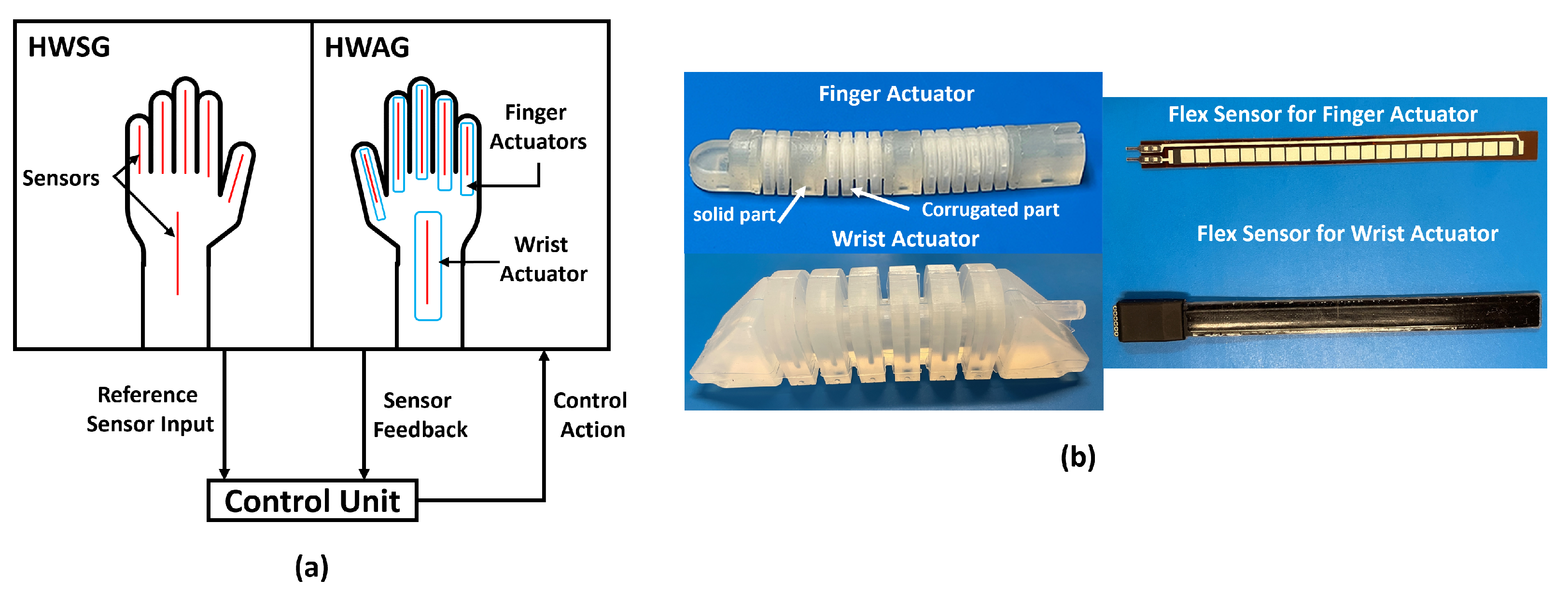
The system consists of a hand and wrist exoskeleton (HWE) and a pneumatic control unit (Figure 1). Each component of the system is described below.
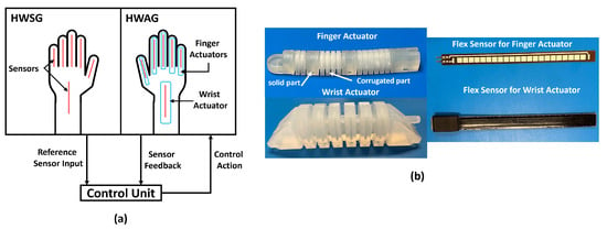
Figure 1.
(a) Soft robotic hand and wrist exoskeleton system for rehabilitation, consisting of a hand and wrist exoskeleton and a pneumatic control unit; (b) a finger and a wrist actuator along with corresponding flex sensors.
2.1. Hand and Wrist Exoskeleton
The HWE comprises six soft pneumatic actuators: one actuator for each finger and one for the wrist. The actuators are made of silicone rubber and designed as hollow structures with a corrugated geometry to allow for expansion and angular motion, which can be found in more detail in our previous reports [10,13]. The actuators are secured on the dorsal side of the hand to apply flexion to the fingers and wrist. A flex sensor is placed beneath each actuator to measure the real-time angle and velocity of the finger and wrist joints. The angle given by each flex sensor is the flexion/extension angle of each joint and is denoted by . The data from flex sensors provide feedback to a pneumatic control unit to send the control action (air flow rate) to the actuators to achieve the required angles and velocities of joints. Our previous works showed the design, numerical simulations, range of motion studies, and force calculation for finger [10] and wrist [13] actuators. From these studies, the flexion/extension ranges of motion for the fingers and wrist are /0° and /−45°, respectively. The torques produced by finger and wrist actuators at 70 kPa pressure are 0.06 Nm and 1.8 Nm, respectively. The corrugated structures of each finger actuator are designed to correspond to the MCP, PIP, and DIP joints of the fingers and thumb, with the ability to achieve the natural human range of motion of those joints. The only differentiation between finger designs is the solid sections that link the corrugated structures together, where the solid sections are different lengths according to the average size of adult male hands.
2.2. Fabrication
CAD models of the actuators for each finger (thumb, index, middle, ring, and little) and the wrist were created with SOLIDWORKS software. Using these CAD models, molds were designed and 3D-printed using a stereolithography printer (ProJet 6000 HD SLA). The molds were designed for a polymer compression molding process, where silicone rubber (XIAMETER® RTV-4234-T4, Xiameter®, Krayden (Denver, CO, USA)) material was used. A detailed manufacturing process for the finger and wrist actuators is explained in [10,13], respectively.
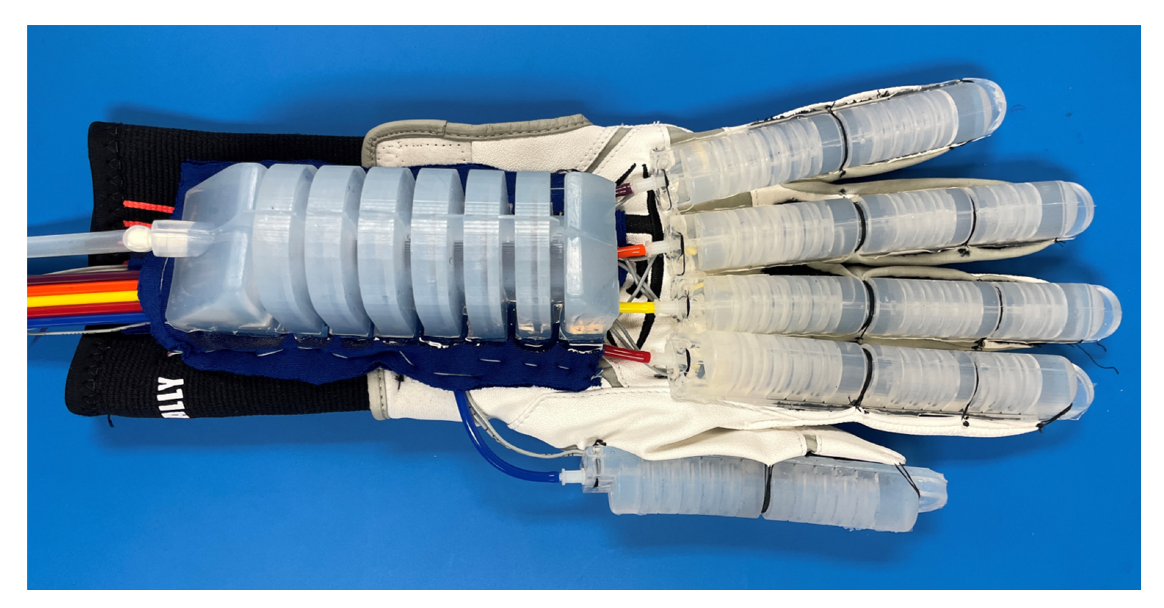
To assemble the entire HWE, a commercially available glove and wrist sleeve were sewn together to create a foundation for attaching the actuators and flex sensors. The flex sensors were embedded beneath each actuator, and all the soft actuators were secured on the dorsal side of the wearable garment, as shown in Figure 2. To attach the flex sensors for fingers, pockets were sewn on the glove, where the flex sensors were placed inside the pockets. For the wrist joint, a flex sensor was bonded to the wrist sleeve using silicone material. Actuators were sewn to the glove and wrist sleeve on top of the sensors. Resistance-based flex sensors (https://www.sparkfun.com/products/8606 (accessed on 5 January 2024)) were used for the finger actuators, and a capacitance-based flex sensor (https://www.nitto.com/jp/ja/nbt/products/1-axis-soft-flex-sensor/ (accessed on 5 January 2024)) was used for the wrist. Both of these sensors measure the bending angle . Resistance-based flex sensors are not capable of bi-directional angle measurements, but they are sufficient for sensing finger motions. Capacitance-based flex sensors can measure in both directions, which is required for sensing wrist motion.
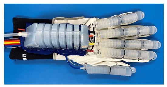
Figure 2.
Soft robotic hand and wrist exoskeleton.
2.3. Pneumatic Control Unit Architecture
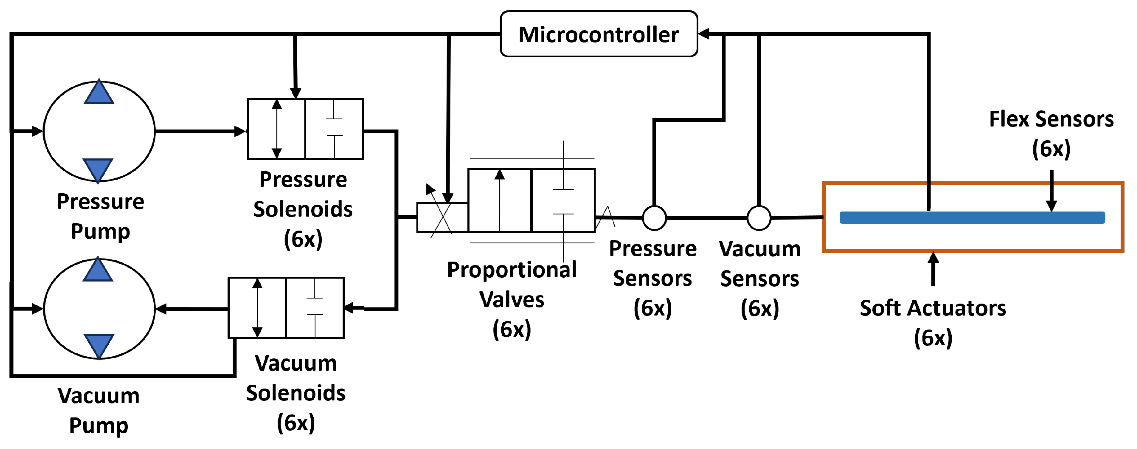
A pneumatic control unit is used to achieve the required angular movement of the finger and wrist joints by using feedback from each flex sensor to control the pneumatic actuation. As shown in Figure 3, this unit consists of electronic (six flex sensors, six pressure sensors, six vacuum sensors) and pneumatic (six soft actuators, six proportional valves, six pressure solenoid valves, six vacuum solenoid valves, one pressure pump, one vacuum pump) components, and a microcontroller is used to control the operation of each component. Pressure and vacuum sensors are used to measure the pressure/vacuum in each actuator to ensure that the pressure/vacuum stays within safe limits. The flex sensors and pressure sensors provide real-time data to the microcontroller so that they can command the valves to open/close accordingly to achieve the desired finger and wrist movements. Solenoid valves are used to interchange the direction of airflow to create pressure or vacuum, which flexes or extends the actuators, respectively. Proportional valves are used to change the airflow rate to the actuators by using a pulse width modulation (PWM) signal from the microcontroller to vary the orifice size. Therefore, the air flow rate (PWM signal) is the required control action to control angular movement and velocity of the finger and wrist joints. The model, dimensions, and weight of each component of the control box are listed in Table 1. The total weight of the control box, including all of the components, is 1.4 kg.
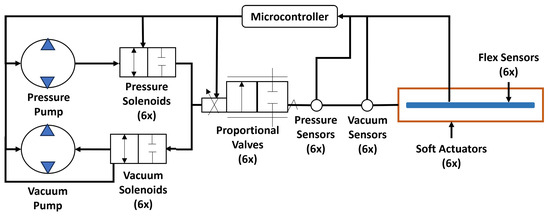
Figure 3.
Schematic diagram of all the components of the pneumatic control unit used for hand and wrist exoskeleton system.

Table 1.
Specifications of components used in control box.
3. Hand and Wrist Exoskeleton Control Algorithm
A PD-based control is used for the soft robotic hand and wrist exoskeleton system (Figure 4). The reference angle and velocity values (, ) are chosen according to the rehabilitation exercises being performed, and they act as input for the closed-loop PD controller. The control algorithm ensures that the finger and wrist joints follow the reference input trajectories (, ). The flex sensors provide current angle and velocity data (, ), which are feedback for the controller. Due to the noise seen in the raw angle data () from flex sensors, spectral analysis is performed, and the data are filtered through a first-order low-pass filter with a cut-off frequency of 1 Hz. Further, velocity is computed using the filtered angle data from the flex sensors. As shown in Equation (1), errors e and are computed by finding the difference between the reference values (, ) and feedback values (, ). The PD controller utilizes these errors to compute the PWM signal that would initiate the required control action. This calculated PWM signal is fed to the proportional valves to control the airflow rate such that the actuators achieve the targeted angle and velocity set by the reference input trajectories. The control action () is calculated according to Equation (2). The PWM signal should vary between 0 () and 4096 () to operate the proportional valve. When the PWM signal is ≤0, the proportional valve is fully closed; conversely, when the PWM signal is ≥4096, the proportional valve is fully open.

Figure 4.
PD control for soft robotic hand and wrist exoskeleton.
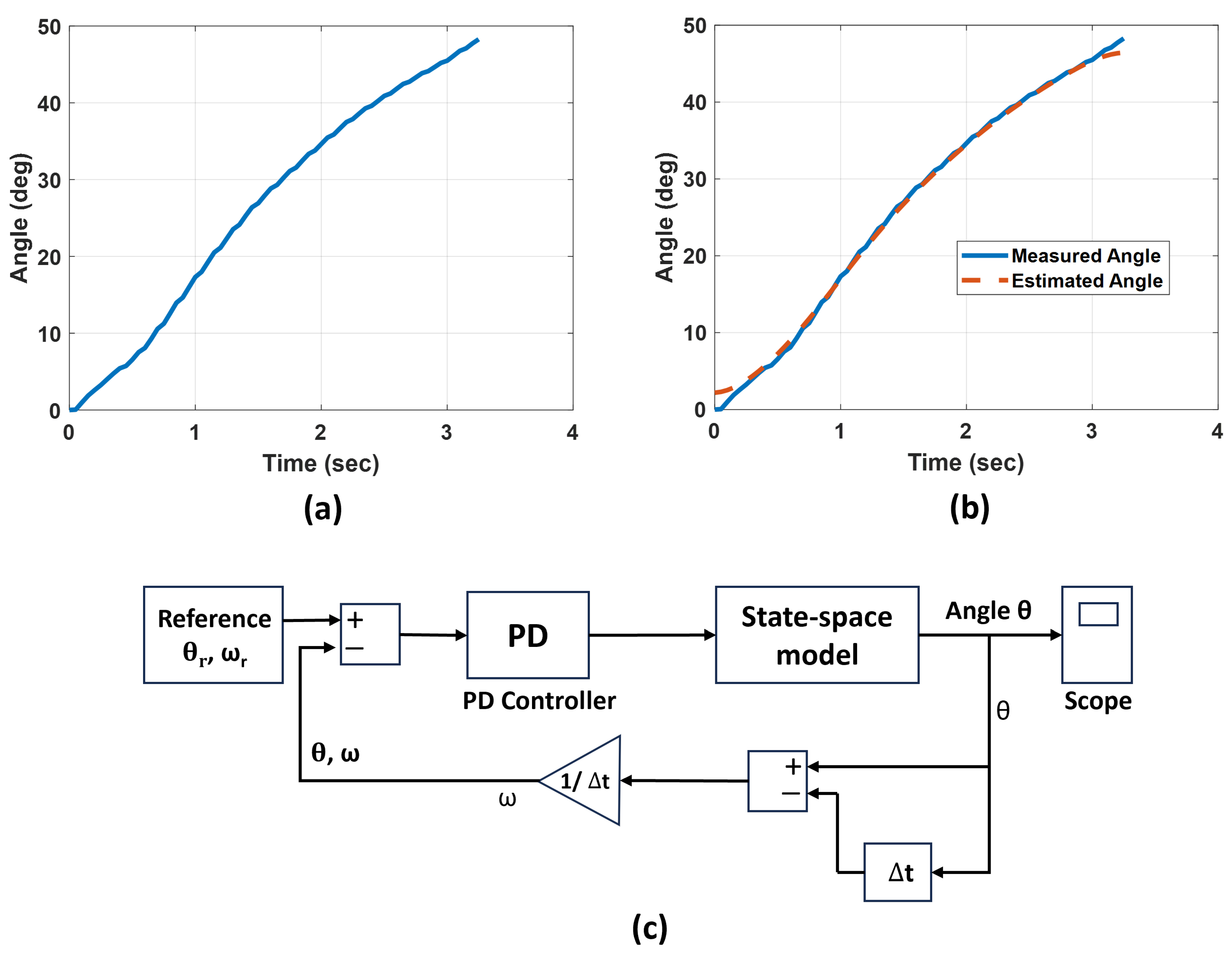
Here, and are the parameters of the PD control algorithm. The and control parameters are determined for each actuator by their model estimation. For example, the estimation process for the wrist actuator includes recording the experimental data of the bending angle of the wrist actuator, as shown in Figure 5a. These data are collected while PWM is 2500, which means the proportional valve is approximately 60% open. This PWM is chosen as the operation of the system is smooth without any jerks at this value. Despite the soft actuator’s bending behavior being nonlinear, experimental findings indicate that a linear approximation is acceptable when the system functions within an angular motion range of 0–50 degrees. Therefore, the input PWM to the proportional valve and the output bending angle of the soft robotic actuator can be approximated as a linear system.
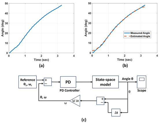
Figure 5.
Control parameters estimation (a) experimental recorded wrist angle, (b) output of the state-space model compared with experimental values, (c) simulation model of control with estimated state-space model.
The state-space formulation [25] for a linear time-invariant dynamic system can be stated as follows:
Here, x is the state vector, y is the system output, u is the system input, A is the state matrix, B is the input matrix, C is the output matrix, and is the input time delay. In our case, the system output y is angle and the system input u is the PWM signal to the proportional valve.
To determine the model parameters of a soft pneumatic actuator, the system input PWM is maintained as a constant, while the system output angle is obtained through experimentation (Figure 5a). By utilizing experimental data comprising PWM and , the system can be estimated by employing an iterative estimation technique aimed at minimizing prediction errors between the experimental data and the estimated system output [26]. Therefore, using the input data (PWM = 2500) to the proportional valve and the acquired output data , the state-space model is identified. The state matrix A, input matrix B, and output matrix C are estimated. The output of the estimated state-space model is compared with the experimental recording shown in Figure 5b.
Using the estimated state-space model, a simulation model of the control algorithm is constructed in Matlab/Simulink, as shown in Figure 5c. The simulation model has a state-space model block, a reference command block, and a PD control block. Using the simulation method, the PD parameters of the wrist actuator are estimated. The estimated parameters and are 8 and 6.5, respectively. These values are further tuned using the experimental data, which resulted in = 8.1 and = 6.7.
The finger actuators have different geometry, but the same linear trend of experimental data is found for the finger actuators in the linear range of 0–180 degrees. Therefore, the same procedure (as discussed above for the wrist actuator) is followed to estimate and parameters for finger actuators.
Table 2 shows the tuned values of and parameters.

Table 2.
Tuned control parameters and for finger and wrist actuators.
Figure 4 also shows the two modes: full assistance and partial assistance. In the full assistance mode, the controller will control the exoskeleton to provide assistance to reach the desired trajectories without any wait time. In the partial assistance mode, the controller will wait for t seconds for the user to try to reach the target joint angles. If the user cannot reach the required joint angles after t seconds, the controller will assist further. The time t can be selected by the physician according to the patient’s mobility or the therapy requirements.
4. Experimental Setup
4.1. Exercises for Experimental Tests
To understand the capabilities of the HWE to assist a user (no participants were recruited for this study. All the experimental tests were performed on one of our team members. At our institution, we are permitted to perform benchtop tests among research staff during the development phase of research without any IRB or regulatory approval) in performing rehabilitation exercises, the system was programmed to assist in three hand and wrist exercises while the PD control was verified for its performance. The three different exercises were as follows: (1) flexion/extension, (2) a dumbbell exercise, and (3) an object pick and place task. The first exercise is a ROM exercise, commonly used to rehabilitate hand and wrist joints. The other two exercises are task-specific and were chosen due to the importance of testing the HWE’s capability to assist in functional tasks that are known to effectively restore motor function [22,23,24]. All exercises were performed in two different modes: full assistance mode and partial assistance mode. In the full assistance mode, the user keeps their hand in a relaxed position without any voluntary movement so that the exoskeleton provides full assistance for flexion/extension motion to the finger and wrist joints. In the partial assistance mode, the control system is designed to wait for a set time of t seconds to allow the user to attempt to reach the reference angle themselves, and if they cannot reach it within the timeframe, the system will activate to assist the user in completing the remaining angular trajectory. During the data collection for the partial assistance mode, the volunteer was asked to perform the specified motion and to stop moving before reaching the reference trajectory to allow the system to assist in completing the targeted motion. Overall, a total of six tests were performed (three types of exercises; two modes per exercise), where the volunteer performed an exercise three times consecutively for each test.
Before performing the test, the reference angles () for each joint were determined by having a user perform the exercise to record the angle values required to complete the task. Those values were used as input reference angles for the PD controller to perform the test. Reference velocities () were set to /s and /s for the fingers and wrist, respectively, for all exercises. After setting the inputs, the sequence of flexion/extension of the fingers and wrist joints was set in the algorithm to perform the required task. During each test, the achieved angles were recorded to estimate the error between the input reference () and the achieved angles ().
4.1.1. Flexion/Extension Exercise
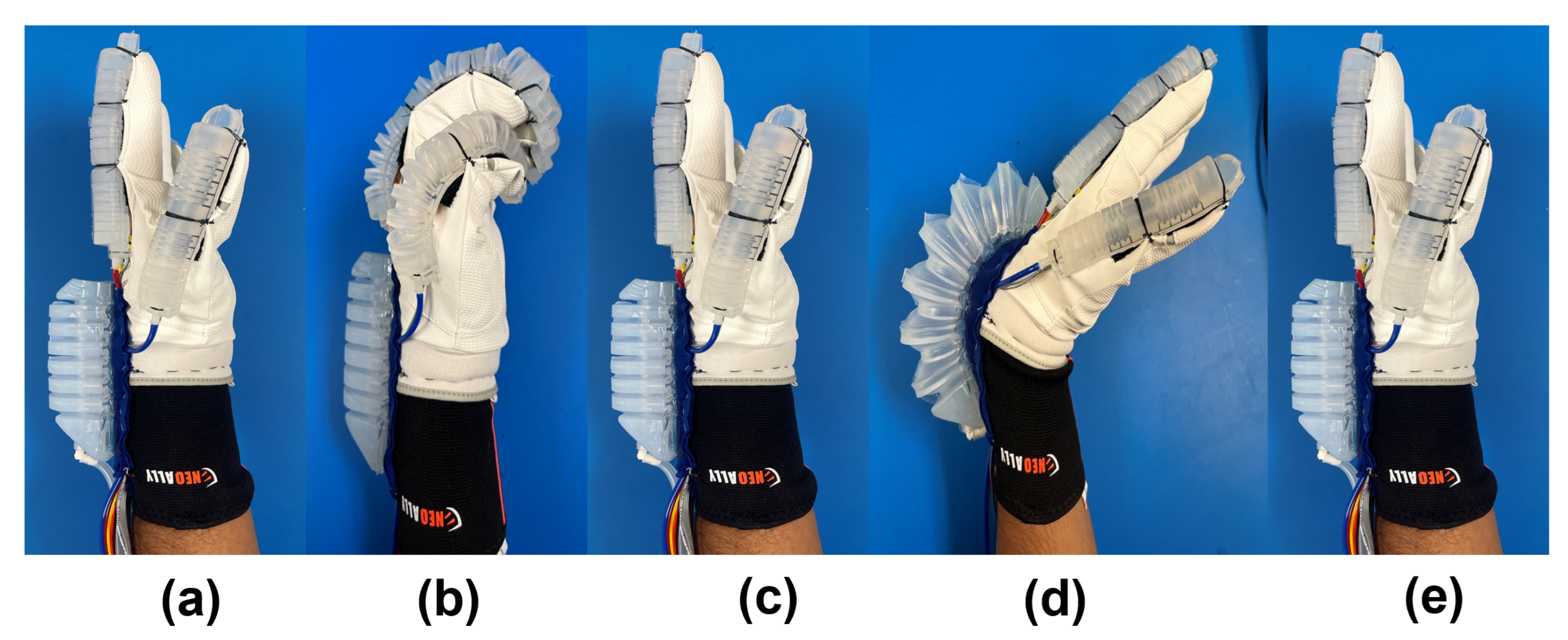
The flexion/extension rehabilitation exercise was performed following the steps shown in Figure 6. First, (a) the hand and wrist start at a relaxed neutral position. Next, (b) the finger actuators were pressurized to flex, and (c) then they were vacuumed to extend back to 0 degrees. Finally, (d) the wrist actuator was pressurized to create flexion movement of the wrist joint, (e) followed by vacuuming to extend the wrist joint back to 0 degrees.
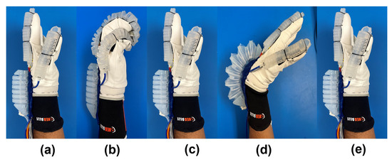
Figure 6.
Steps involving the sequential flexion/extension rehabilitation exercise for finger and wrist joints using the exoskeleton: (a) relaxed neutral position, (b) fingers flexion, (c) fingers extension, (d) wrist flexion, and (e) wrist extension.
For the flexion/extension (CPM) rehabilitation exercise, the reference flexion/extension angles () for the fingers and wrist were set to /0° and /0°, respectively. These set angles can be chosen based on the user’s range of motion (ROM). The thumb flexion/extension was set to a higher angle /0° to avoid interference with the fingers during flexion. During flexion, the thumb was flexed first, followed by the fingers to cover the thumb, to further minimize obstruction among the thumb and fingers.
4.1.2. Dumbbell Exercise
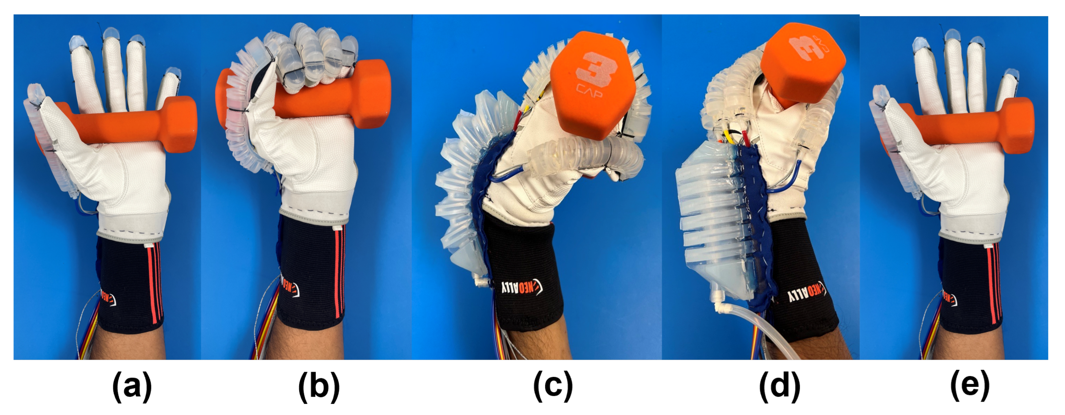
To demonstrate a task-oriented rehabilitation exercise, a dumbbell exercise was performed in the five steps shown in Figure 7. First, (a) a dumbbell was placed in the hand without any movement of the hand or wrist. (b) The finger actuators were pressurized to flex (: thumb = , index = , middle = , ring = , little = ) and hold the dumbbell. (c) The wrist actuator was pressurized to flex (: wrist = ) the joint and perform the dumbbell exercise. (d) The wrist actuator was vacuumed to extend the joint back to the initial position. Last, (e) the fingers were extended to release the dumbbell.
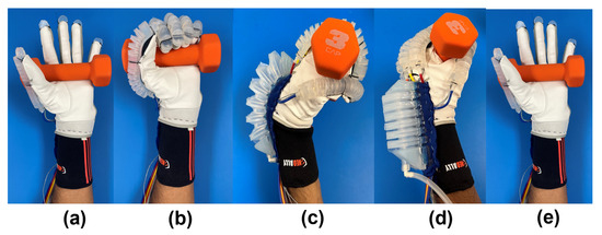
Figure 7.
Steps involving sequential flexion/extension of the finger and wrist joints using exoskeleton for performing a dumbbell exercise.
4.1.3. Object Pick and Place
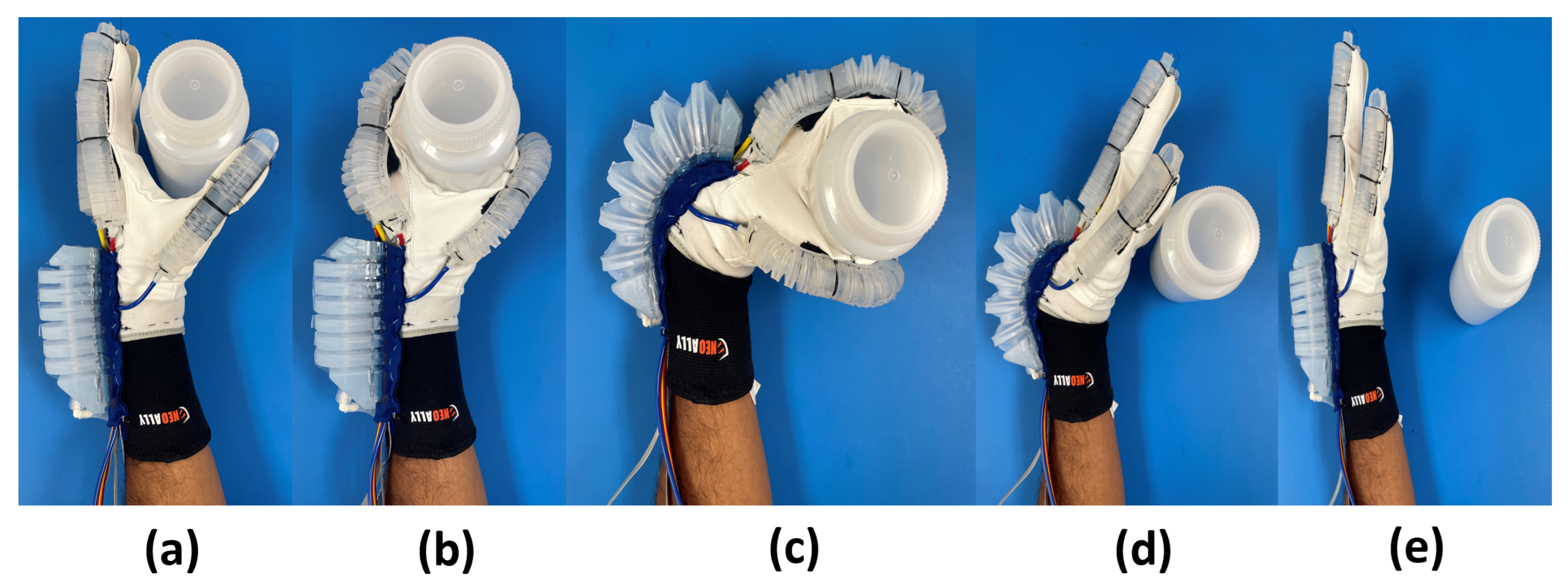
The object pick and place task was performed in the five steps shown in Figure 8. First, (a) the hand was placed at an initial position close to the object. Next, (b) the finger actuators were pressurized to flex (: thumb = , index = , middle = , ring = , little = ) and grasp the object. (c) The wrist actuator was pressurized to flex (: wrist = ) the joint and move the object from its initial position to the target position. (d) The finger actuators were vacuumed to extend and place the object at the target position. Finally, (e) the wrist actuator was vacuumed to extend the joint, returning the hand back to the initial position.
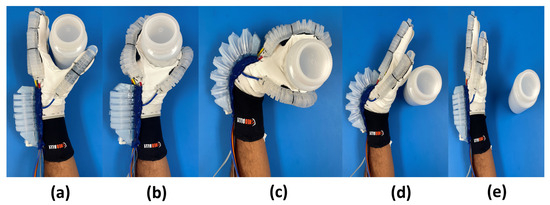
Figure 8.
Steps involving sequential flexion/extension of the finger and wrist joints using exoskeleton for performing an object pick and place task.
5. Experimental Results
The purpose of the data analysis is to verify that the PD control was able to ensure the fingers and wrist actuator could assist the human in reaching the reference angles, as well as to ensure the system performed the finger and wrist motions in the correct sequence for each exercise. During each exercise, the reference angle and velocity values (, ) are set for each flexion/extension movement. The PD controller ensures that the system follows the required reference movements. The error between the reference angles () and the average of the achieved angles () for the three cycles shows the performance of the PD controller. As discussed earlier, each test was performed in two modes. In the case of the partial assistance mode, a wait time t was set for 5 s, where the volunteer was allowed to move at any velocity during this time while also maintaining a joint angle that is well below .
5.1. Flexion/Extension Exercise
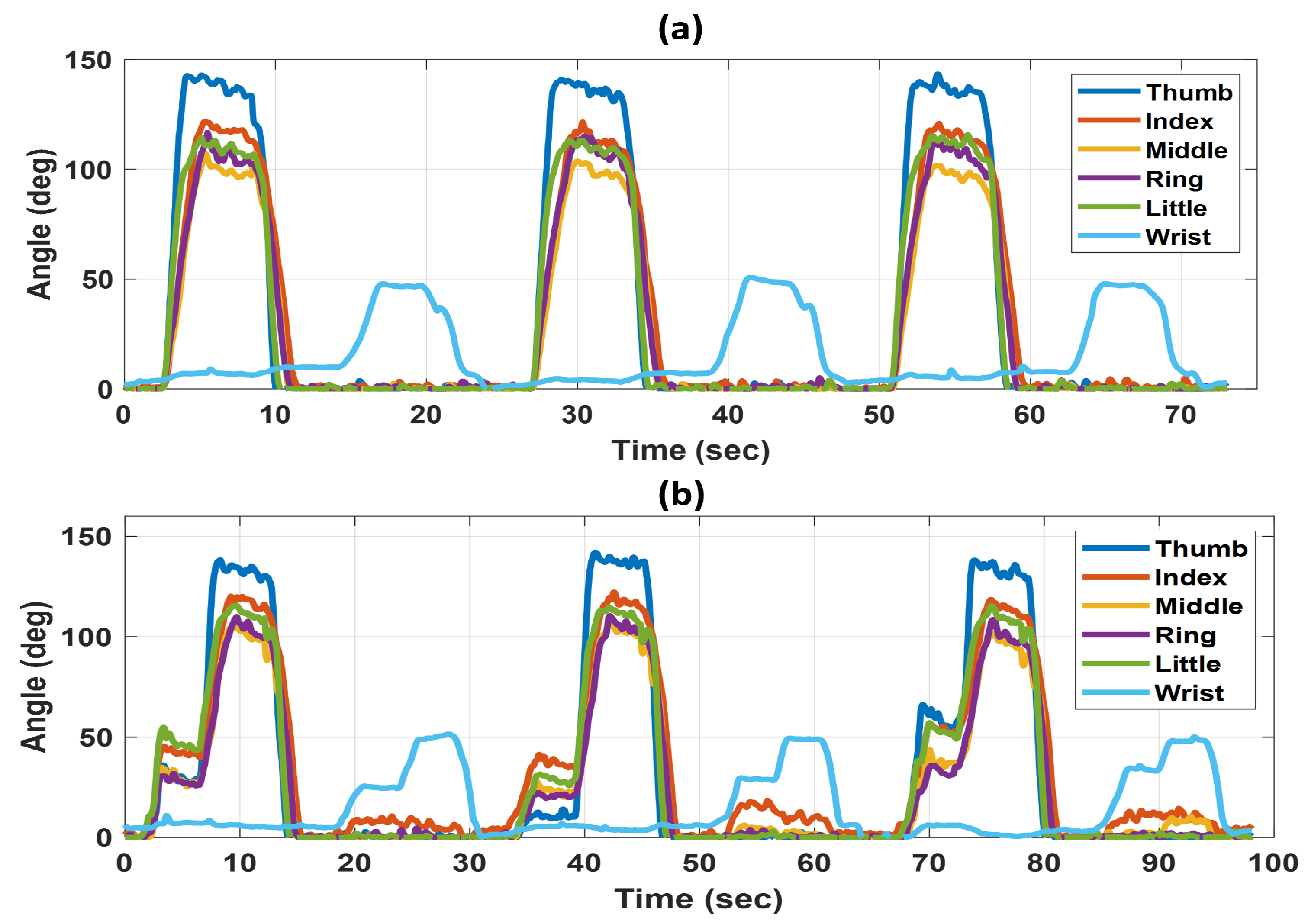
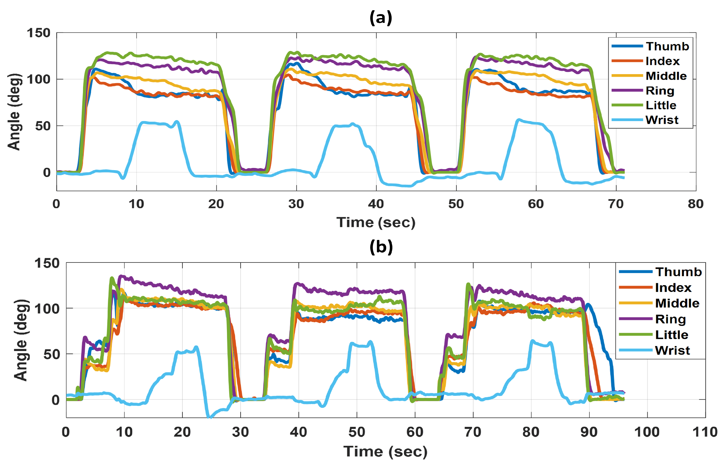
Figure 9 shows the change in angle for each joint during the flexion/extension exercise in the two different modes. The exercise was performed for three cycles, as shown in Figure 9a, with full assistance from the exoskeleton. Each cycle consists of flexion/extension of the fingers and wrist in sequence. Figure 9b shows the partial assistance mode. In this mode, at the beginning of each flexion movement, the system waited for 5 s before initiating motion assistance. From Figure 9b, it is clear that when the user does not achieve the input reference values for the fingers (thumb = , other fingers = ) and wrist (), then the exoskeleton assists in finishing the remaining trajectory.
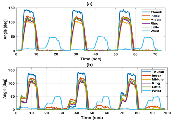
Figure 9.
Change in joint angles over time for three flexion/extension cycles in (a) full assistance mode and (b) partial assistance mode.
The results from Figure 9 show that the HWE can assist the user in performing flexion/extension exercises. The PD controller helps to reach the desired reference inputs for each finger and wrist joint in both full and partial assistance modes. In the full assistance mode, the average errors in the angles achieved for the thumb, index, middle, ring, little, and wrist joints are , , , , , and , respectively. In the partial assistance mode, the average errors in the angles achieved for the thumb, index, middle, ring, little, and wrist joints are , , , , , and , respectively.
5.2. Dumbbell Exercise
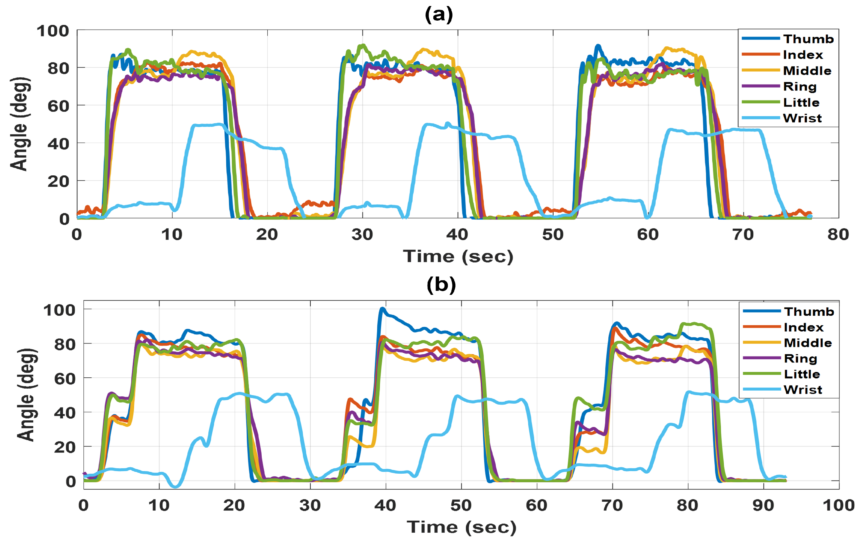
As discussed in the experimental setup section, the dumbbell exercise was performed in five steps. Figure 10a,b show the changes in angles for all joints in the full and partial assistance modes, respectively, while performing three repetitions of the dumbbell exercise.
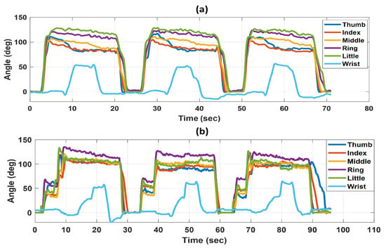
Figure 10.
Change in joint angles over time for three cycles of the dumbbell exercise in (a) full assistance mode and (b) partial assistance mode.
The results from Figure 10 show that the HWE can assist the user in performing dumbbell exercises in the correct sequence. The PD controller helps to reach the desired reference inputs for each finger and wrist joint in both full and partial assistance modes. In the full assistance mode, the average errors in the angles achieved for the thumb, index, middle, ring, little, and wrist joints are , , , , , and , respectively. In the partial assistance mode, the average errors in the angles achieved for the thumb, index, middle, ring, little, and wrist joints are , , , , , and , respectively.
5.3. Object Pick and Place
As discussed in the experimental setup section, the object pick and place task was performed in five steps. Figure 11a,b show the changes in angles of all joints for the full and partial assistance modes, respectively, while picking and placing an object three times.
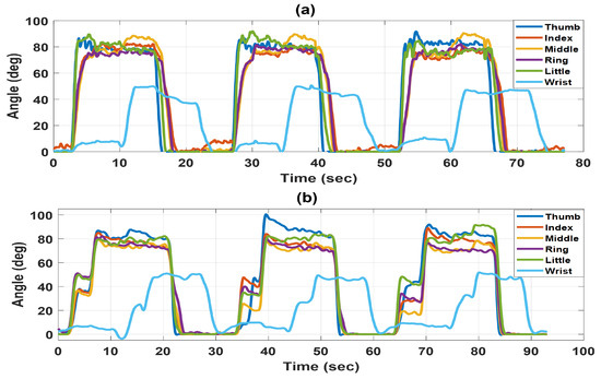
Figure 11.
Change in joint angles over time for three cycles of the pick and place exercise in (a) full assistance mode and (b) partial assistance mode.
The results from Figure 11 show that the HWE can assist the user in performing the object pick and place task in the correct sequence. The PD controller helps to reach the desired reference inputs for each finger and wrist joint in both full and partial assistance modes. In the full assistance mode, the average errors in the angles achieved for the thumb, index, middle, ring, little, and wrist joints are , , , , , and , respectively. In the partial assistance mode, the average errors in the angles achieved for the thumb, index, middle, ring, little, and wrist joints are , , , , , and , respectively.
6. Discussion
The results from the three experimental tests verify that the exoskeleton can be used for continuous passive motion (CPM) rehabilitation as well as task-oriented rehabilitation exercises due to its capability to flex and extend joints of the hand and wrist in a variety of sequences. The exoskeleton enables the user or physician to select the targeted range of motion for any rehabilitation exercise to accommodate various ranges of motion and speeds using PD control. More task-oriented exercises involving hand and wrist movement can be explored, similar to the dumbbell exercise and object pick and place task. The exoskeleton is capable of assisting motion in both full and partial assistance modes. This implies that the exoskeleton can be used to provide compensatory movement based on the user’s mobility. However, the compensation of joint stiffness and spastic response were not evaluated as the test was performed with a healthy volunteer. The partial assistance mode can be utilized to evaluate the motor recovery of a patient by monitoring the angle at which they reach before assistance is provided by the exoskeleton.
As the experimental tests were performed by a human user rather than using an anthropomorphic model, there is some noise in the angle values. We have observed that there are errors between the set reference and the achieved angle values. Contributions to these errors can come from how the human user bends their fingers and holds the object during reference data collection versus during the actual test. Additionally, the control parameters are estimated by approximating the bending of the actuators as a linear system, which could cause some of the errors. In the partial assistance mode of the flexion/extension exercise (Figure 9b), there are some noticeable small movements of the finger joints during flexion of the wrist joint. These small movements were observed to be from the natural movement of the user’s fingers during wrist flexion. In these experiments, the partial assistance mode is only applied during flexion of the joints. If the patient has contractions in their hands, they could benefit from practicing extending their hands, and in the partial assistance mode, there can be a set time to give them a chance to extend their hand before the vacuum provides assistance in extension. One of the main limitations of this exoskeleton is that the wrist joint is only designed for flexion/extension and, therefore, cannot be used for radial/ulnar deviation exercises. A video has been added as a Supplementary Material to show the functionality of the pneumatically actuated soft robotic hand and wrist exoskeleton.
7. Conclusions
This work demonstrated a soft robotic hand–wrist exoskeleton controlled using a single PD-based controller to provide assistance to hand and wrist joints in a coordinated manner. The exoskeleton can be programmed to create different sequences of hand and wrist movements. Also, the controller was successfully tested for two modes: full assistance and partial assistance from the exoskeleton. In the future, force sensors will be embedded into the exoskeleton that will allow us to control the grip force according to the object to be handled in a task. Additionally, the wrist actuator will be modified to allow for radial/ulnar deviation motion assistance. Future work will also include testing the exoskeleton with targeted conditions such as post-stroke hand and wrist impairments.
Supplementary Materials
The following supporting information can be downloaded at: https://www.mdpi.com/article/10.3390/act13050180/s1. The video shows the functionality of the hand and wrist exoskeleton.
Author Contributions
Conceptualization, I.S., A.J., Y.G. and M.B.J.W.; methodology, I.S., Y.G. and M.B.J.W.; software, T.R., I.S., B.B. and Y.G.; validation, T.R., I.S., Y.G. and B.B.; formal analysis, T.R., I.S., B.B., A.J., R.M. and M.B.J.W.; writing—original draft preparation, T.R., I.S., A.J. and M.B.J.W.; writing—review and editing, I.S., A.J. and M.B.J.W.; supervision, R.M. and M.B.J.W. All authors have read and agreed to the published version of the manuscript.
Funding
This research received no external funding.
Data Availability Statement
The raw data supporting the conclusions of this article will be made available by the authors on request.
Acknowledgments
We want to thank Veysel Erel and Aida Nasirian for their help during the manufacturing of actuators.
Conflicts of Interest
The authors declare no conflicts of interest.
Abbreviations
The following abbreviations are used in this manuscript:
| PD | Proportional derivative |
| CPM | Continuous passive motion |
| HWE | Hand and wrist exoskeleton |
| PWM | Pulse width modulation |
References
- Askim, T.; Bernhardt, J.; Salvesen, Ø.; Indredavik, B. Physical activity early after stroke and its association to functional outcome 3 months later. J. Stroke Cerebrovasc. Dis. 2014, 23, e305–e312. [Google Scholar] [CrossRef] [PubMed]
- Bardi, E.; Gandolla, M.; Braghin, F.; Resta, F.; Pedrocchi, A.L.; Ambrosini, E. Upper limb soft robotic wearable devices: A systematic review. J. Neuroeng. Rehabil. 2022, 19, 87. [Google Scholar] [CrossRef] [PubMed]
- Longatelli, V.; Antonietti, A.; Biffi, E.; Diella, E.; D’Angelo, M.G.; Rossini, M.; Molteni, F.; Bocciolone, M.; Pedrocchi, A.; Gandolla, M. User-centred assistive SystEm for arm Functions in neUromuscuLar subjects (USEFUL): A randomized controlled study. J. Neuroeng. Rehabil. 2021, 18, 4. [Google Scholar] [CrossRef] [PubMed]
- Molteni, F.; Gasperini, G.; Cannaviello, G.; Guanziroli, E. Exoskeleton and end-effector robots for upper and lower limbs rehabilitation: Narrative review. PM R 2018, 10, S174–S188. [Google Scholar] [CrossRef] [PubMed]
- Moggio, L.; de Sire, A.; Marotta, N.; Demeco, A.; Ammendolia, A. Exoskeleton versus end-effector robot-assisted therapy for finger-hand motor recovery in stroke survivors: Systematic review and meta-analysis. Top. Stroke Rehabil. 2022, 29, 539–550. [Google Scholar] [CrossRef] [PubMed]
- Reissner, L.; Fischer, G.; List, R.; Giovanoli, P.; Calcagni, M. Assessment of hand function during activities of daily living using motion tracking cameras: A systematic review. Proc. Inst. Mech. Eng. Part H J. Eng. Med. 2019, 233, 764–783. [Google Scholar] [CrossRef] [PubMed]
- Balasubramanian, S.; Klein, J.; Burdet, E. Robot-assisted rehabilitation of hand function. Curr. Opin. Neurol. 2019, 23, 661–670. [Google Scholar] [CrossRef] [PubMed]
- Heo, P.; Gu, G.M.; Lee, S.J.; Rhee, K.; Kim, J. Current hand exoskeleton technologies for rehabilitation and assistive engineering. Int. J. Precis. Eng. Manuf. 2012, 13, 807–824. [Google Scholar] [CrossRef]
- Lum, P.S.; Godfrey, S.B.; Brokaw, E.B.; Holley, R.J.; Nichols, D. Robotic approaches for rehabilitation of hand function after stroke. Am. J. Phys. Med. Rehabil. 2012, 91, S242–S254. [Google Scholar] [CrossRef] [PubMed]
- Haghshenas-Jaryani, M.; Manvar, M.; Wijesundara, M.B. Torque characterization of a novel pneumatic soft-and-rigid hybrid actuator. In Dynamic Systems and Control Conference; American Society of Mechanical Engineers: New York, NY, USA, 2017; Volume 58271, p. V001T30A007. [Google Scholar]
- Fulton, P.V.; Löhlein, S.; Paredes-Acuña, N.; Berberich, N.; Cheng, G. Wrist Exoskeleton Design for Pronation and Supination using Mirrored Movement Control. In Proceedings of the 2021 20th International Conference on Advanced Robotics (ICAR), Ljubljana, Slovenia, 6–10 December 2021; IEEE: Piscateville, NJ, USA, 2021; pp. 575–580. [Google Scholar]
- Greco, C.; Weerakkody, T.H.; Cichella, V.; Pagnotta, L.; Lamuta, C. Lightweight Bioinspired Exoskeleton for Wrist Rehabilitation Powered by Twisted and Coiled Artificial Muscles. Robotics 2023, 12, 27. [Google Scholar] [CrossRef]
- Singh, I.; Erel, V.; Gu, Y.; Lindsay, A.R.; Patterson, R.M.; Swank, C.; Wijesundara, M.B. Development of Soft Pneumatic Actuator Based Wrist Exoskeleton for Assistive Motion. In Proceedings of the 2023 IEEE/ASME International Conference on Advanced Intelligent Mechatronics (AIM), Seattle, WA, USA, 28–30 June 2023; IEEE: Piscateville, NJ, USA, 2023; pp. 359–366. [Google Scholar]
- Ates, S.; Haarman, C.J.; Stienen, A.H. SCRIPT passive orthosis: Design of interactive hand and wrist exoskeleton for rehabilitation at home after stroke. Auton. Robot. 2017, 41, 711–723. [Google Scholar] [CrossRef]
- Troncossi, M.; Mozaffari Foumashi, M.; Mazzotti, C.; Zannoli, D.; Parenti-Castelli, V. Design and manufacturing of a hand-and-wrist exoskeleton prototype for the rehabilitation of post-stroke patients. Quaderni del DIEM–GMA. In Atti della Sesta Giornata di Studio Ettore Funaioli; 2012; pp. 111–120. Available online: https://www.researchgate.net/publication/258278331_Design_and_Manufacturing_of_a_Hand-and-Wrist_Exoskeleton_Prototype_for_the_Rehabilitation_of_Post-Stroke_Patients (accessed on 5 January 2024).
- Pezent, E.; Rose, C.G.; Deshpande, A.D.; O’Malley, M.K. Design and characterization of the OpenWrist: A robotic wrist exoskeleton for coordinated hand-wrist rehabilitation. In Proceedings of the 2017 International Conference on Rehabilitation Robotics (ICORR), London, UK, 17–20 July 2017; IEEE: Piscateville, NJ, USA, 2017; pp. 720–725. [Google Scholar]
- Amirabdollahian, F.; Ates, S.; Basteris, A.; Cesario, A.; Buurke, J.; Hermens, H.; Hofs, D.; Johansson, E.; Mountain, G.; Nasr, N.; et al. Design, development and deployment of a hand/wrist exoskeleton for home-based rehabilitation after stroke-SCRIPT project. Robotica 2014, 32, 1331–1346. [Google Scholar] [CrossRef]
- Rose, C.G.; Sergi, F.; Yun, Y.; Madden, K.; Deshpande, A.D.; O’Malley, M.K. Characterization of a hand-wrist exoskeleton, READAPT, via kinematic analysis of redundant pointing tasks. In Proceedings of the 2015 IEEE International Conference on Rehabilitation Robotics (ICORR), Singapore, 11–14 August 2015; IEEE: Piscateville, NJ, USA, 2015; pp. 205–210. [Google Scholar]
- Shahid, T.; Gouwanda, D.; Nurzaman, S.G.; Gopalai, A.A. Moving toward soft robotics: A decade review of the design of hand exoskeletons. Biomimetics 2018, 3, 17. [Google Scholar] [CrossRef] [PubMed]
- Pérez Vidal, A.F.; Rumbo Morales, J.Y.; Ortiz Torres, G.; Sorcia Vázquez, F.D.J.; Cruz Rojas, A.; Brizuela Mendoza, J.A.; Rodríguez Cerda, J.C. Soft exoskeletons: Development, requirements, and challenges of the last decade. Actuators 2021, 10, 166. [Google Scholar] [CrossRef]
- Wijesundara, M.B.J.; Carrigan, W.; Haghshenas Jaryani, M. Fluid-Driven Actuators and Related Methods. U.S. Patent 1,091,2701, 9 February 2021. [Google Scholar]
- Bosch, J.; O’Donnell, M.J.; Barreca, S.; Thabane, L.; Wishart, L. Does task-oriented practice improve upper extremity motor recovery after stroke? A systematic review. ISRN Stroke 2014, 2014, 504910. [Google Scholar] [CrossRef]
- Winstein, C.J.; Wolf, S.L.; Dromerick, A.W.; Lane, C.J.; Nelsen, M.A.; Lewthwaite, R.; Cen, S.Y.; Azen, S.P. Effect of a task-oriented rehabilitation program on upper extremity recovery following motor stroke: The ICARE randomized clinical trial. JAMA 2016, 315, 571–581. [Google Scholar] [CrossRef] [PubMed]
- Alsubiheen, A.M.; Choi, W.; Yu, W.; Lee, H. The effect of task-oriented activities training on upper-limb function, daily activities, and quality of life in chronic stroke patients: A randomized controlled trial. Int. J. Environ. Res. Public Health 2022, 19, 14125. [Google Scholar] [CrossRef] [PubMed]
- Mikova, L.; Gmiterko, A.; Hroncova, D. State space representation of dynamical systems. Am. J. Mech. Eng. 2016, 4, 385–389. [Google Scholar]
- Van Overschee, P.; De Moor, B. Subspace Identification for Linear Systems: Theory—Implementation—Applications; Springer Science & Business Media: Berlin/Heidelberg, Germany, 2012. [Google Scholar]
Disclaimer/Publisher’s Note: The statements, opinions and data contained in all publications are solely those of the individual author(s) and contributor(s) and not of MDPI and/or the editor(s). MDPI and/or the editor(s) disclaim responsibility for any injury to people or property resulting from any ideas, methods, instructions or products referred to in the content. |
© 2024 by the authors. Licensee MDPI, Basel, Switzerland. This article is an open access article distributed under the terms and conditions of the Creative Commons Attribution (CC BY) license (https://creativecommons.org/licenses/by/4.0/).

