Abstract
Handling suspended loads in cluttered environments is critical due to the oscillations arising while the load is traveling. Exploiting active control algorithms is often unviable in industrial applications, due to the necessity of installing sensors on the load side, which is expensive and often impractical due to technological limitations. In this light, this paper proposes a trajectory planning method for underactuated, non-flat, non-minimum phase spatial gantry crane moving in structured cluttered environments. The method relies on model inversion. First, the system dynamics is partitioned into actuated and unactuated coordinates and then the load displacements are described as a non-linear separable function of these. The unactuated dynamic is unstable; hence, the displacement, velocity, and acceleration references are modified through the output redefinition technique. Finally, platform trajectory is computed, and the desired displacements of the load are obtained. The effectiveness of the proposed method is assessed through numerical and experimental tests performed on a laboratory testbed composed by an Adept Quattro robot moving a pendulum. The load is moved in a cluttered environment, and collisions are avoided while simultaneously tracking the prescribed trajectory effectively.
1. Introduction
Cranes are widely employed devices for handling heavy-weight goods during manufacturing processes [1]. These devices consist of a platform moving along a linear, planar, or spatial trajectory to transport a load which is connected to the platform through wires, ropes, or chains. This architecture leads to a pendulum-like dynamic that is prone to the onset of oscillations during the motion. Controlling oscillating loads is not a trivial task. In particular, in the presence of structured cluttered environments with obstacles, avoiding collisions is fundamental for safety reasons; moreover, in the meantime, achieving adequate performances in terms of trajectory tracking and contouring is important to fulfill the manufacturing requirements. Such a problem is often tackled through the adoption of advanced motion planning algorithms to avoid the installation of additional sensors on the load side, which are needed if feedback control is adopted. On the other hand, semi-active and active control techniques are widely adopted due to their flexibility and robustness, which is major with respect to open-loop methods (see, e.g., [2] and the references therein).
Motion planning methods for multibody systems, devoted to precise track a reference trajectory, are often based on the inversion of the system dynamic model [3,4]. The solution of such problem is not trivial in the case of underactuated systems, where the number of a system’s degrees of freedom (DOFs) is greater than the number of independent actuators [5]. In this scenario, the actuated coordinate trajectory should be computed to achieve the desired displacements, which are reasonably referred to the load to satisfy a certain manufacturing task [6]. This problem has been mainly tackled by the researchers using the servo constraint method [7,8], which introduces rheonomous active constraints for the desired displacements.
Many underactuated systems are non-minimum phases for certain outputs of interest [6,9]. Motion planning for these kinds of systems is even more challenging; indeed, the system internal dynamics is unstable [10]. Hence, the model inversion yields a set of ODEs that diverge during their numerical integrations [6,11]. This problem has been tackled in [11] for flexible robotic arms. Lately, the servo constraint method has been applied in [12,13] through the output redefinition technique, which refines the desired output to stabilize the ODEs describing the system internal dynamics enabling their integration. It should be noted that this method relies on a linearized combination of the output with respect to the actuated and unactuated generalized coordinates. Output redefinition, integrated mechanical design through a counter-weight mass and state control, has been used and compared in [14] to control a parallel robot with flexible links. Recently, funnel control has been proposed in [15] for non-minimum phase manipulators, and then it has been used in [16] together with the servo-constraint method. A direct multiple shooting method has been proposed in [17] for underactuated manipulators. Robustness requirements have been included in the literature when dealing with the problem of trajectory tracking by relaxing some conditions related to the exact attainment of the desired load trajectory (see, e.g., [18]).
Besides proposing methods for the trajectory tracking of underactuated systems, some papers considered the issues related to handling loads by means of cranes in cluttered environments. In particular, in [19], a method for the simultaneous path-tracking and load swing damping in cranes moving in a workspace with obstacles has been proposed. A hybrid approach [20] with both feedforward and feedback controllers has been proposed for a cluttered work environment. A flatness-based method, for a crane moving in the presence of obstacles, has been developed in [21]. The adoption of a cascade tracking controller together with trajectory planning has been proposed in [22] for an environment with obstacles. Recently, non-linear model predictive control has also been applied in [23] to a gantry crane to avoid obstacles. The collision avoidance problem has also been tackled in [24] for a double-pendulum moved through a linear platform.
The literature review highlights that the control of non-minimum phase underactuated systems, in particular cranes, is an actual topic of both industrial and academic research interest. In this light, this paper proposes a model inversion method to precisely track the desired trajectory in an underactuated, non-flat, non-minimum phase gantry crane. It should be noted that a remarkable feature of the proposed method is being capable of handling position references of just differentiability class C2 in contrast to flatness-based approaches, such as in [5,21]. Indeed, if the system is flat, these methods require high-order polynomials that impose high actuation forces and speeds. Moreover, another important feature of the proposed method is that it ensures finding a causal solution; hence, no pre-actuation is required.
The proposed method relies on the partitioning of the system model into actuated and unactuated coordinates; then, by exploiting the representation of the desired output as a non-linear separable function of these coordinates, it can provide the system internal dynamics. Since the system comprises a non-minimum phase, the internal dynamics are stabilized through the output redefinition technique. Then, the trajectories of the three actuated coordinates of the spatial crane are computed by defining a non-linear map between the actuated and unactuated coordinates, which is again a strength of the proposed method with respect to those proposed in the literature, which often rely on linearization.
The effectiveness of the method, together with its ease of implementation and its low computational effort, is assessed through numerical simulations on the model of a spatial gantry crane moving a suspended load. Then, experiments are carried out on a laboratory testbed composed by an Adept Quattro robot, which mimics the actuated platform, and a pendulum representing the suspended load. The system displacements are collected through Vicon high-speed infrared cameras. The capability of achieving high performances with negligible tracking and contouring errors, also avoiding collisions in a cluttered environment with obstacles, is demonstrated.
Besides providing a motion planning method which is effective and precise in trajectory tracking, the main contributions of the proposed work are the following:
- A complex system, which is not common in the literature, is considered here. The system features an additional degree of freedom with respect to the previous work of the authors [9], and it allows us to impose an additional controlled output and hence perform a spatial task.
- A comprehensive approach is proposed to handle the problem of tip control in the presence of structured obstacles. The resulting method therefore covers the issue of designing smooth reference trajectories and translates them into suitable commanded trajectories for the actuated coordinates.
- The experimental application to some complex test cases—by exploiting an industrial setup—is proposed, and experimental benchmarking against other methods is carried out.
2. Model of the System
Let us consider a spatial gantry crane moving a suspended load. The system is sketched in Figure 1. The platform coordinates are denoted through vector . Two unactuated independent coordinates are adopted to represent the relative motion between the platform and the suspended load, and they are collected in vector . is the angle between the pendulum projection on the xz plane and the vertical z axis, and is the angle measured from the xz plane, leading to the suspended load coordinate vector [25]:
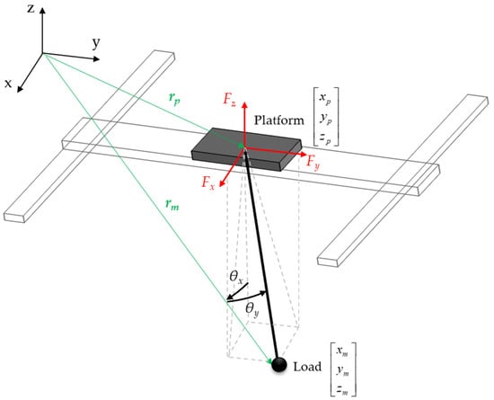
Figure 1.
Sketch of the spatial overhead crane with the suspended load.
The system has 5 degrees of freedom (DOFs) that are collected into the vector with independent coordinates .
Exploiting the Lagrange formalism and minimal coordinates representation, the non-linear model of the system is obtained through Ordinary Differential Equations, which can be written in the following concise form:
The mass matrix M(q) is
where s( ) and c( ), respectively, denote the sine and cosine trigonometric functions. The crane platform masses are, respectively, Mx, My, and Mz; m is the suspended load mass. Vector h collects the centripetal terms, as follows:
The gravitational and damping forces are gathered in vector g, which is defined as follows:
where g represents gravity acceleration. Damping is modeled through the viscous friction terms related to the crane platform (cx, cy, cz) and to the load (cθx, cθy). Finally, three independent actuation forces are assumed, which are collected in vector .
The constant actuation matrix is with being the 3 × 3 identity matrix and being the 3 × 2 null matrix. Then, rank(B) = 3, i.e., the system is underactuated since the number of independent actuators is lower with respect to the number of DOFs [9].
3. The Proposed Trajectory Planning Method
3.1. Method Formulation
The goal of the proposed paper is to make the coordinates rm of the suspended load track the desired position reference defined through the reference trajectory , thus leading for the following trajectory design problem: compute such that
Equation (6) is often denoted as the servo-constraint [7,8,26].
Additionally, it is required that rp has no pre-actuation; therefore, just causal solutions are wanted.
It should be noted that the task consists of precisely tracking both the spatial path and the trajectory in time while avoiding uncontrolled oscillations of the suspended load.
The non-linear model in Equation (2) can be conveniently written in the following concise, partitioned form:
Let us now consider just the second row of matrix Equation (7):
Such ODEs represent the relative motion between the platform and the suspended load, described through the angular coordinates ; hence, it represents the dynamics of the unactuated coordinates when excited by gravity forces and by the motion of the actuated ones, rp. These equations are usually denoted as the second-order nonholonomic constraint [27], which defines the feasible trajectories. Additionally, it is not integrable [27] and hence cannot be brought back to an algebraic one.
Equation (8) can be transformed into the so-called internal dynamics by writing it as a function of the unactuated coordinates and of the related reference (and their time derivatives) by removing the dependence on the actuated coordinates. To this end, the internal dynamics can be obtained by exploiting the formulation of the controlled output as a separable function of rp and :
with
The servo-constraint in Equation (6) is therefore written as follows:
The derivatives of Equation (11) with respect to time yields the servo-constraints at a velocity level of
and at acceleration level of
Matrix J is the Jacobian matrix:
while vector collects the centripetal acceleration terms:
The substitution of Equation (13) in Equation (8) yields the exact formulation of the internal dynamics, i.e., no linearization is required despite the non-linear relationship between rp and :
The ODEs in Equation (16) can be solved through a numerical integration to compute the trajectory of required for making load tracking the imposed reference while satisfying the second-order nonholonomic constraints (i.e., those that are allowed by the system dynamics).
Let , , and denote such position, speed, and acceleration vectors solving Equation (16), respectively. Then, the consistent trajectory of the actuated coordinates can be obtained by inverting the servo-constraints in Equations (11)–(13) as follows:
As long as Equation (17) is solvable, these values are, in principle, the optimal trajectory to be commanded to the crane platform to make the load track the desired output.
3.2. Analysis of the Internal Dynamics
For certain choices of the desired output, the system becomes a “non-minimum phase” [9,14,16]. Controlling non-minimum phase systems is cumbersome since their internal dynamics are unstable [28]; hence, they cannot be integrated since diverging outputs are obtained.
A common approach to assess if the internal dynamics are unstable consists of the analysis of zero dynamics [11], which are the internal dynamics where the output is constrained to be zero for all the time. Hence, zero dynamics are obtained by setting in Equation (17), i.e.,
Equation (18) is now independent from the reference trajectory; further, it can be linearized with respect to a stable equilibrium point, such as . Now, if the linearized counterpart of Equation (18) has some eigenvalues lying on the right half of the complex plane (i.e., their real part is positive), then the numerical integration of Equation (16) will be unstable.
3.3. Redefinition of the Output
The internal dynamics’ stabilization goal is pursued in this paper through the “output redefinition” strategy, as proposed by the authors in [9]. Output redefinition is performed by modifying the original output into a fictious one to stabilize internal dynamics and enable the numerical integration of Equation (16).
In this light, in this paper, the length of the cable is redefined by imposing a different length of the cable lr, where 0 < lr < l, in such a way that
In turn, the redefined desired output and its time derivatives and become
The internal dynamics with the redefined output is simply inferred from Equation (18), i.e.,
Then, the stable ODE in Equation (21) can be numerically integrated with the numerical methods proposed in the literature for multibody systems (see, e.g., [29]), providing , , , which can be substituted in Equation (17) with the redefined length lr to obtain the command trajectory for the actuated coordinates.
In this paper, by linearizing Equation (21) and setting , the redefined zero dynamics becomes
Equation (22) highlights that with the original output, i.e., lr = l, zero dynamics’ mass matrix is null, leading to two infinite value positive eigenvalues. Then, the system’s zero dynamics are stabilized by redefining the output.
4. Method Assessment
4.1. Simulations and Experiments
The proposed method effectiveness is assessed through numerical simulations performed in MATLAB-Simulink to track two spatial trajectories with the load, i.e., by setting . The values of the system parameters, employed in the proposed model-based method to design the trajectories, are summarized in Table 1.

Table 1.
System parameter values.
The trajectories that will be considered are
- A spatial Archimedean spiral (Section 4.2).
- A complex path with obstacles (Section 4.3).
For all the tests that are proposed hereafter, the numerical integration is performed using a Runge–Kutta ODE4 integration scheme with a step size equal to 1 ms.
Moreover, the obtained trajectories are tested on a laboratory testbed composed by an Adept Quattro parallel robot (Livermore, CA, USA) mimicking the platform and a pendulum, which is the suspended load. The displacements of the robot and of the load are recorded through Vicon Vantage V5 motion capture cameras (Yarnton, Oxford, UK) with sample frequency set to 400 Hz. The experimental setup is shown in Figure 2.
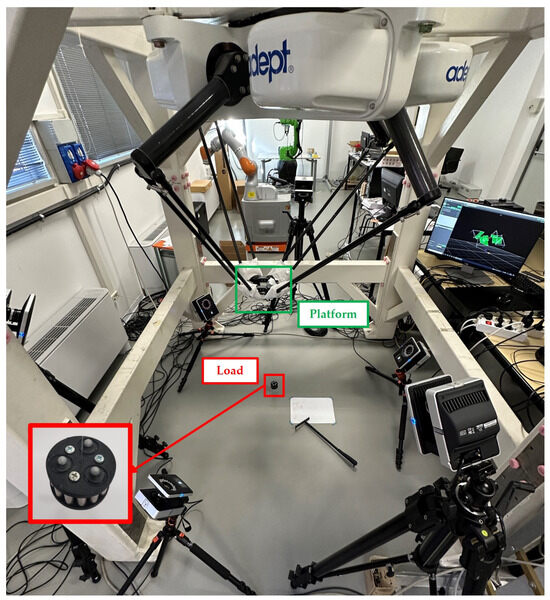
Figure 2.
The experimental setup.
4.2. Archimedean Spiral: Results
In this test, the desired displacements for the suspended load are defined according to an Archimedean spiral. The trajectory is defined through , where the number of revolutions is N = 5, a = 0.15 m is the initial radius, and b = a/N. The angle is , which varies according to a rest-to-rest 5th degree polynomial law of motion with a motion time equal to 15 s and a 2 s rest time after the motion. The following equations hold for the motion of the load mass in the x and y directions:
A rest-to-rest 5th degree polynomial law is also adopted to define the desired motion in the z direction with = 0.3 m. The reference trajectory in the time domain for all the coordinates is shown in Figure 3a; in the cartesian space, it is shown in Figure 3b.
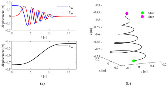
Figure 3.
Archimedean spiral: (a) desired load displacements in the time domain; (b) desired load trajectory in the space.
The proposed algorithm is applied to compute the trajectory of the actuated platform coordinates, which are shown in Figure 4. As expected, the evolution of the actuated coordinates is remarkably different with respect to the reference trajectory. Indeed, the motion planning aims at compensating for the unactuated pendulum dynamics. Then, the obtained actuated coordinate trajectory is applied to the model of the system, and the obtained load trajectory is shown in Figure 4. It highlights that the load trajectory matches the desired reference. Hence, the proposed algorithm is valid for tracking the desired spatial trajectory.
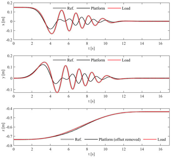
Figure 4.
Archimedean spiral numerical results: reference trajectory, platform, and load displacements.
The Adept Quattro robot platform is also commanded (in the experimental setup in Figure 2) with the platform coordinates previously computed. The spatial displacements of the robot, pendulum, and the desired trajectory are shown in Figure 5. Once again, the results provide evidence that the desired motion is correctly achieved, corroborating the effectiveness of the proposed method. Figure 6 shows a comparison of the simulated and experimental results for both the platform and for the suspended load. Figure 6a compares the actual platform trajectory and the planned one: differences are due to the robot controller bandwidth and to the motion interpolation algorithm (which are implemented in the native Adept controller). In addition, Figure 6b compares the trajectories of the pendulum’s tip, whose motion is slightly perturbated by the mentioned uncertainty sources.
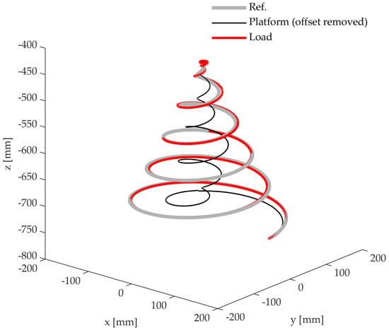
Figure 5.
Archimedean spiral experimental results: reference trajectory, platform, and load displacements in the workspace.
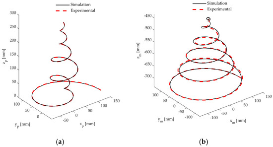
Figure 6.
Archimedean spiral comparison of the simulated and experimental results: (a) platform; (b) suspended load.
An evaluation of the impact of model parameter’s uncertainty is performed through numerical robustness. The effects of a variation of the model parameters with respect to those adopted in the motion planning stage were considered by varying both the load mass m and the load damping coefficients cθx, cθy (denoted for brevity cθ). In detail, the mass varied in the range of ±50% with respect to the nominal value and the damping of ±30%. Then, the obtained load trajectory was computed in the system’s simulator while using the nominal platform trajectory (i.e., the one planned by assuming nominal model parameters), which was compared with the one obtained by assuming nominal model parameters. The effect of such perturbation on the load tracking capability was computed by considering
with
Superscript “pert” denotes the load trajectory obtained by perturbing the load mass and damping, while “nom” denotes the trajectory obtained by simulating the system with its nominal parameters. Figure 7 shows the RMS value , where it is possible to note that < 1.1 mm for all the perturbation sets, and this value is obtained for the largest parameter variations (i.e., when the load mass increases by +50% and the load damping is reduced to −30%).
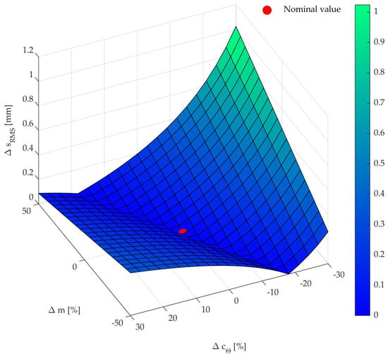
Figure 7.
RMS value of the load trajectory variation while perturbing the load mass and damping coefficients simultaneously.
4.3. Path with Obstacles: Results
A sample trajectory, with motion time equal to 30 s, is partitioned as follows:
- 1st part: Rest-to-motion 5th degree polynomial.
- 2nd part: Constant speed along two axes (null on the third).
- 3rd part: Spline 4-3-4 trajectory.
- 4th part: Constant speed along an axis (null on the other two axes).
- 5th part: Motion-to-rest 5th degree polynomial.
A rest phase of 5 s is imposed after the motion phase to evaluate the residual oscillations.
The trajectory, which is composed of 24 points (summarized in Table 2), is designed to overcome the 5 obstacles sketched in Figure 8, and the motion is executed starting from a vertex of the workspace and ending on the laterally opposed vertex. The overall motion path in the workspace with obstacles is shown in Figure 8, while the trajectory of the desired load position, velocity, and acceleration is provided in Figure 9.

Table 2.
Points used to generate the trajectory in the path with obstacles.
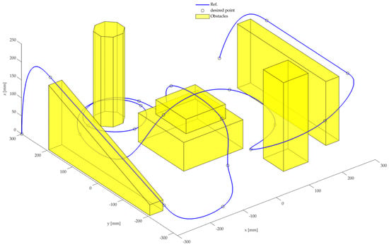
Figure 8.
Reference trajectory in the workspace with obstacles.
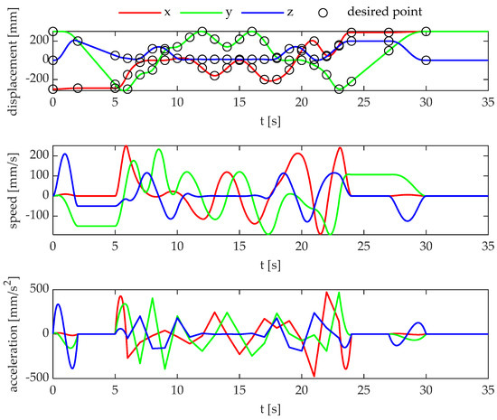
Figure 9.
Path with obstacles: reference trajectory.
The motion planning algorithm proposed in this paper is applied to compute the platform displacements, and then the obtained load trajectory is simulated in MATLAB/Simulink (version R2022a), allowing us to obtain the results that are shown in Figure 10. It is evident that the load properly tracks the desired reference; hence, the method also handles tight maneuver spaces. Therefore, it is capable of avoiding obstacles in cluttered environments. Further, it simultaneously ensures remarkable performances in terms of trajectory and path tracking.
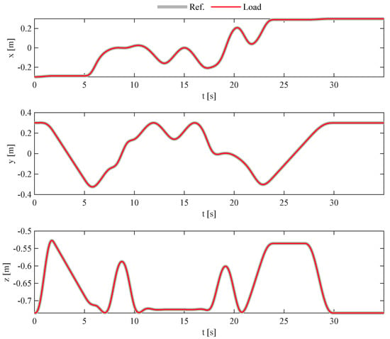
Figure 10.
Path with obstacles. Numerical results: reference trajectory, platform, and load displacements.
The platform’s trajectory obtained with the proposed method is applied to the experimental setup shown in Figure 2. Moreover, it was compared to the results obtained with the application of the input shaping technique [30,31] (also denoted as “IS”) and by applying the desired trajectory directly to the platform (hereafter denoted as “Rigid” planning), thus neglecting the flexible dynamics of the load.
The displacements of the load in the experimental tests with the application of different platform trajectories are shown in Figure 11, while the top and side views of the same tests are shown, respectively, in Figure 12a,b for ease of understanding. It is worth noting that the experimental tests were conducted to obtain the results that are shown in Figure 9 and Figure 10, without the presence of obstacles in the workspace, which were excluded to obtain a fair comparison between the methods and to avoid unwanted oscillations caused by impacts.
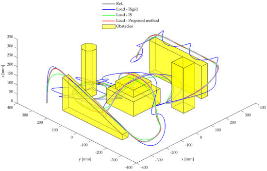
Figure 11.
Path with obstacles. Experimental results with three-dimensional view: reference trajectory and load displacements with different methods.
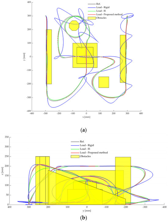
Figure 12.
Path with obstacles. Experimental results with different methods: top (a) and side (b) views.
The experimental results highlight that the desired trajectory is correctly tracked with the proposed method. Conversely, the IS smooths the trajectory in case of spatial references, and the load tracks a different path with respect to the desired one. The results are even worse in the case of rigid planning; indeed, the load oscillates, and the obtained displacements are completely different with respect to the target ones. In addition, the abovementioned tests suggest that, once the obstacles are installed, the proposed method can avoid collisions with the obstacles, while IS and rigid planning cannot.
The obstacles were manufactured with polystyrene and installed in the system, and the same tests with different methods, which are discussed in Figure 11 and Figure 12, were performed once again. In particular, Figure 13, Figure 14 and Figure 15 provide some meaningful snapshots that were taken during the experimental tests. The frames in Figure 13, together with the previously mentioned results, provide evidence that no collisions were experienced through the proposed method. Indeed, the obstacles were not touched by the load, which correctly tracked the prescribed reference. Conversely, in the case of application of the trajectory computed through the IS technique, Figure 14c reports the first impact experienced against the top level of the middle two-level obstacle and another impact with the same obstacle, which is shown in Figure 14f. Moreover, Figure 14d,e show the collisions with the octagonal base prism. Additionally, in Figure 14g, the impact with the square base prism is provided; in the subsequent Figure 14h,i, such obstacle collapsed on the floor.
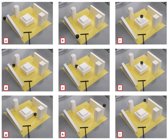
Figure 13.
Experimental snapshots in the path with obstacle test: the proposed method: (a) start, (b–h) intermediate frames, (i) end.
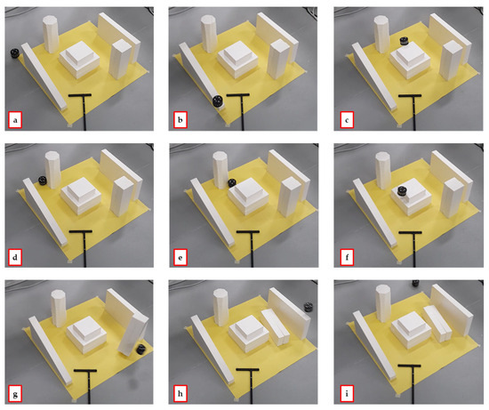
Figure 14.
Experimental snapshots in the path with obstacle test: input shaping: (a) start, (b–h) intermediate frames, (i) end.
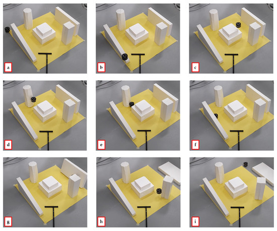
Figure 15.
Experimental snapshots in the path with obstacle test: rigid planning: (a) start, (b–h) intermediate frames, (i) end.
The difficulties are exacerbated in the case of “Rigid” motion planning; indeed, Figure 15d–h show a sequence of impacts leading to undesired motion or, even worse, to a collapse of the obstacles in the workspace.
5. Conclusions
This paper proposes the application of a trajectory tracking method developed by the authors to the challenging problem of a spatial gantry crane moving a suspended load in a structured, cluttered environment. The method is capable of handling underactuated, non-flat, non-minimum phase systems, and it aims to plan the motion of an actuated platform through model inversion. The proposed technique relies on the partitioning of the coordinates into actuated and unactuated ones, and then the load displacements are described as a non-linear separable function of these coordinates. Since the load unactuated dynamics is non-minimum phase, its inversion is non-trivial. Indeed, it is unstable and then its numerical integration is unviable. Then, the desired output, i.e., the suspended load trajectory, is redefined through the output redefinition technique, which stabilizes the unactuated internal dynamics. Once the unactuated coordinates are obtained through numerical integration, the platform trajectory is finally computed through the non-linear map defined between the actuated and unactuated coordinates.
The effectiveness of the proposed method is tested in two challenging scenarios: the execution of a spatial Archimedean spiral with motion time equal to 15 s and in the tracking of a spatial path in a structured cluttered environment in the presence of five obstacles. First, numerical results are carried out, highlighting the effectiveness of the method. In particular, the effectiveness of the proposed method is confirmed by the low tracking error obtained, whose maximum value is 0.8 mm along the x-axis for the spiral and 0.25 mm on the y-axis for the path with obstacles. Secondly, experimental tests are performed on a laboratory testbed composed by an Adept Quattro parallel robot, which mimics the actuated platform, and a suspended load. The experimental results, again, confirm the benefits of the proposed method and support its efficacy in executing challenging paths in the presence of obstacles. In our future works, the proposed method will be improved and extended to be applied to systems with more degrees of underactuation.
Author Contributions
Conceptualization, J.B., D.R. and I.T.; methodology, J.B., D.R. and I.T.; software, J.B. and I.T.; validation, J.B. and I.T.; formal analysis, J.B., D.R. and I.T.; investigation, J.B., D.R. and I.T.; resources, D.R.; data curation, I.T.; writing—original draft preparation, D.R. and I.T.; writing—review and editing, J.B., D.R. and I.T.; visualization, I.T.; supervision, D.R.; project administration, D.R.; funding acquisition, D.R. All authors have read and agreed to the published version of the manuscript.
Funding
This research was funded by the Ministero dell’Università e della Ricerca PRIN 2020 “Extending Robotic Manipulation Capabilities by Cooperative Mobile and Flexible Multi-Robot Systems (Co-MiR)” (Prot. 2020CMEFPK).
Data Availability Statement
The dataset used in this study can be made available upon request from the authors.
Acknowledgments
The authors would like to thank Martino Verziaggi for providing help in the execution of the tests.
Conflicts of Interest
The authors declare no conflicts of interest.
References
- Mojallizadeh, M.R.; Brogliato, B.; Prieur, C. Modeling and Control of Overhead Cranes: A Tutorial Overview and Perspectives. Annu. Rev. Control 2023, 56, 100877. [Google Scholar] [CrossRef]
- Richiedei, D.; Tamellin, I.; Trevisani, A. Beyond the Tuned Mass Damper: A Comparative Study of Passive Approaches to Vibration Absorption through Antiresonance Assignment. Arch. Comput. Methods Eng. 2021, 29, 519–544. [Google Scholar] [CrossRef]
- Devasia, S. Optimal Output Trajectory Redesign for Invertible Systems. J. Guid. Control Dyn. 1996, 19, 1189–1191. [Google Scholar] [CrossRef]
- Devasia, S.; Chen, D.; Paden, B. Nonlinear Inversion-Based Output Tracking. IEEE Trans. Autom. Control 1996, 41, 930–942. [Google Scholar] [CrossRef]
- Tonan, M.; Doria, A.; Bottin, M.; Rosati, G. Oscillation-Free Point-to-Point Motions of Planar Differentially Flat under-Actuated Robots: A Laplace Transform Method. Robotica 2024, 42, 1262–1280. [Google Scholar] [CrossRef]
- Bettega, J.; Richiedei, D.; Tamellin, I.; Trevisani, A. Stable Inverse Dynamics for Feedforward Control of Nonminimum-Phase Underactuated Systems. J. Mech. Robot. 2023, 15, 031002. [Google Scholar] [CrossRef]
- Blajer, W.; Kołodziejczyk, K. Control of Underactuated Mechanical Systems with Servo-Constraints. Nonlinear Dyn. 2007, 50, 781–791. [Google Scholar] [CrossRef]
- Seifried, R.; Blajer, W. Analysis of Servo-Constraint Problems for Underactuated Multibody Systems. Mech. Sci. 2013, 4, 113–129. [Google Scholar] [CrossRef]
- Bettega, J.; Richiedei, D.; Tamellin, I.; Trevisani, A. Model Inversion for Precise Path and Trajectory Tracking in an Underactuated, Non-Minimum Phase, Spatial Overhead Crane. J. Vib. Eng. Technol. 2023, 11, 3841–3857. [Google Scholar] [CrossRef]
- Bastos, G. Analysis of Internal Dynamics in Trajectory Tracking Problems. Int. J. Dyn. Control 2023, 11, 2870–2885. [Google Scholar] [CrossRef]
- De Luca, A.; Lucibello, P.; Ulivi, A.G. Inversion Techniques for Trajectory Control of Flexible Robot Arms. J. Robot. Syst. 1989, 6, 325–344. [Google Scholar] [CrossRef]
- Seifried, R. Two Approaches for Feedforward Control and Optimal Design of Underactuated Multibody Systems. Multibody Syst. Dyn. 2012, 27, 75–93. [Google Scholar] [CrossRef]
- Seifried, R. Integrated Mechanical and Control Design of Underactuated Multibody Systems. Nonlinear Dyn. 2012, 67, 1539–1557. [Google Scholar] [CrossRef]
- Morlock, M.; Meyer, N.; Pick, M.-A.; Seifried, R. Real-Time Trajectory Tracking Control of a Parallel Robot with Flexible Links. Mech. Mach. Theory 2021, 158, 104220. [Google Scholar] [CrossRef]
- Berger, T.; Lanza, L. Output Tracking for a Non-Minimum Phase Robotic Manipulator. IFAC-Pap. 2021, 54, 178–185. [Google Scholar] [CrossRef]
- Berger, T.; Drücker, S.; Lanza, L.; Reis, T.; Seifried, R. Tracking Control for Underactuated Non-Minimum Phase Multibody Systems. Nonlinear Dyn. 2021, 104, 3671–3699. [Google Scholar] [CrossRef]
- Bastos, G.; Brüls, O. Analysis of Open-Loop Control Design and Parallel Computation for Underactuated Manipulators. Acta Mech. 2020, 231, 2439–2456. [Google Scholar] [CrossRef]
- Boscariol, P.; Richiedei, D. Robust Point-to-Point Trajectory Planning for Nonlinear Underactuated Systems: Theory and Experimental Assessment. Robot. Comput. Integr. Manuf. 2018, 50, 256–265. [Google Scholar] [CrossRef]
- Boschetti, G.; Caracciolo, R.; Richiedei, D.; Trevisani, A. A Non-Time Based Controller for Load Swing Damping and Path-Tracking in Robotic Cranes. J. Intell. Robot. Syst. 2014, 76, 201–217. [Google Scholar] [CrossRef]
- Kołodziejczyk, K.; Blajer, W. Motion Planning and Control of Gantry Cranes in Cluttered Work Environment. IET Control Theory Appl. 2007, 1, 1370–1379. [Google Scholar] [CrossRef]
- Blajer, W.; Kołodziejczyk, K. Improved DAE Formulation for Inverse Dynamics Simulation of Cranes. Multibody Syst. Dyn. 2011, 25, 131–143. [Google Scholar] [CrossRef]
- Vu, M.N.; Lobe, A.; Beck, F.; Weingartshofer, T.; Hartl-Nesic, C.; Kugi, A. Fast Trajectory Planning and Control of a Lab-Scale 3D Gantry Crane for a Moving Target in an Environment with Obstacles. Control Eng. Pract. 2022, 126, 105255. [Google Scholar] [CrossRef]
- Iftikhar, S.; Faqir, O.J.; Kemgan, E.C. Nonlinear Model Predictive Control of an Overhead Laboratory-Scale Gantry Crane with Obstacle Avoidance. In Proceedings of the 2019 IEEE Conference on Control Technology and Applications (CCTA), Hong Kong, China, 19–21 August 2019; pp. 382–387. [Google Scholar]
- Zhang, W.; Chen, H.; Chen, H.; Liu, W. A Time Optimal Trajectory Planning Method for Double-Pendulum Crane Systems with Obstacle Avoidance. IEEE Access 2021, 9, 13022–13030. [Google Scholar] [CrossRef]
- Boschetti, G.; Caracciolo, R.; Richiedei, D.; Trevisani, A. Moving the Suspended Load of an Overhead Crane along a Pre-Specified Path: A Non-Time Based Approach. Robot. Comput. Integr. Manuf. 2014, 30, 256–264. [Google Scholar] [CrossRef]
- Blajer, W. The Use of Servo-Constraints in the Inverse Dynamics Analysis of Underactuated Multibody Systems. J. Comput. Nonlinear Dyn. 2014, 9, 041008. [Google Scholar] [CrossRef]
- Oriolo, G.; Nakamura, Y. Control of Mechanical Systems with Second-Order Nonholonomic Constraints: Underactuated Manipulators. In Proceedings of the 30th IEEE Conference on Decision and Control, Brighton, UK, 11–13 December 1991; pp. 2398–2403. [Google Scholar]
- Berger, T. Tracking with Prescribed Performance for Linear Non-Minimum Phase Systems. Automatica 2020, 115, 108909. [Google Scholar] [CrossRef]
- García de Jalón, J. Kinematic and Dynamic Simulation of Multibody Systems The Real-Time Challenge; Springer: New York, NY, USA, 1994; Volume 71. [Google Scholar]
- Peláez, G.; Pelaez, G.; Perez, J.M.; Vizán, A.; Bautista, E. Input Shaping Reference Commands for Trajectory Following Cartesian Machines. Control Eng. Pr. 2005, 13, 941–958. [Google Scholar] [CrossRef]
- Singhose, W. Command Shaping for Flexible Systems: A Review of the First 50 Years. Int. J. Precis. Eng. Manuf. 2009, 10, 153–168. [Google Scholar] [CrossRef]
Disclaimer/Publisher’s Note: The statements, opinions and data contained in all publications are solely those of the individual author(s) and contributor(s) and not of MDPI and/or the editor(s). MDPI and/or the editor(s) disclaim responsibility for any injury to people or property resulting from any ideas, methods, instructions or products referred to in the content. |
© 2024 by the authors. Licensee MDPI, Basel, Switzerland. This article is an open access article distributed under the terms and conditions of the Creative Commons Attribution (CC BY) license (https://creativecommons.org/licenses/by/4.0/).