Article

Configuration of the Power Reflux Hydro-Mechanical Transmission System

1
State Key Laboratory of Mechanical Transmission for Advanced Equipment, Chongqing University, Chongqing 400044, China
2
College of Mechanical and Vehicle Engineering, Chongqing University, Chongqing 400044, China
3
College of Instrumentation & Electrical Engineering, Jilin University, Changchun 130061, China
4
State Key Laboratory of Intelligent Agricultural Power Equipment, Luoyang 471003, China
*
Author to whom correspondence should be addressed.
Actuators 2024, 13(4), 120; https://doi.org/10.3390/act13040120
Submission received: 4 February 2024 / Revised: 15 March 2024 / Accepted: 21 March 2024 / Published: 23 March 2024

Abstract

:
The hydro-mechanical transmission system (HMTS) operates either in power split transmission mode (PSTM) or power reflux transmission mode (PRTM). Although PRTM is often ignored as a transition mode, this study reveals that the HMTS operating in the PRTM can accumulate the power input from the power source in the form of reflux power (in some references, scholars also refer to the reflux power as circulating power), thereby enabling the HMTS to exhibit a similar transmission performance as hydrodynamic transmission systems. Accordingly, this study applies the PRTM to the starting of construction vehicles and refers to the HMTS operating only in the PRTM as the power reflux hydro-mechanical transmission system (PHTS). By analyzing the internal relationship between the configuration and the power flow, transmission characteristics, energy storage mechanism, and energy loss mechanism of the PHTS, the optimal PHTS configuration suitable for construction vehicles was explored. The results indicate that reasonable configurations can enable the PHTS to significantly improve the efficiency of the construction vehicle transmission system, reducing energy consumption while ensuring power performance. Expanding the displacement ratio control range of the hydraulic speed regulation mechanism and combining the PRTM with the PSTM in an orderly manner can widen the high-efficiency range of the vehicle transmission system without increasing the number of vehicle gears.

1. Introduction

As a universal component of automatic transmission, torque converters have been widely used in construction vehicles owing to their unique power performance [1,2]. However, torque converters have low transmission efficiency and a narrow high-efficiency range, posing a difficult problem that hinders the wider application of hydrodynamic transmission [3,4]. Therefore, recent research has focused on developing a new transmission system suitable for construction vehicles.
In single power flow transmission systems, the hydrostatic transmission system (HST), composed of a pump and a motor, is the only transmission system with both low-speed torque increase (the low-speed torque increase characteristic is a transmission characteristic that can ensure that the power source always rotates at high speed; the system speed ratio is inversely proportional to the torque ratio; and the maximum torque can be output at a zero speed ratio) and stepless speed regulation, except for automatic transmission. Some scholars have attempted to use HST to compensate for the shortcomings of the torque converter [5,6]. However, large-displacement pumps and motors are expensive, and the transmission efficiency of HST is extremely low under ultra-high-pressure operating conditions [7]. Therefore, HST has been partially used in low-horsepower, compact vehicles, but it is still not widely used in construction vehicles.
In dual power flow transmission systems, the hydro-mechanical transmission system (HMTS) is most suitable for heavy-duty vehicles. HMTS comprises hydrostatic and mechanical transmissions that transmit power in parallel [8]. This system exhibits the stability of hydrostatic transmission and the efficiency of mechanical transmission, and it can achieve high-power, high-efficiency stepless speed change transmission, therefore constituting an ideal transmission form [9].
In the early stages of design, the HMTS was primarily utilized for steering in military tracked vehicles, belonging to one of the dual differential transmission systems [10]. At this point, the two transmission paths of the HMTS transmitted power in parallel and unidirectionally, and only one power split transmission mode existed within the system. However, with the development of vehicle transmission technology, the HMTS began to be applied to transmissions, and this type of transmission has been commonly referred to as the hydro-mechanical continuously variable transmission (HMCVT) [11]. Many scholars have conducted a significant amount of research on HMCVT. Rossetti and Macor introduced the basic structural characteristics of HMCVT; established the mathematical models of mechanical, hydraulic, and control systems; and optimized the transmission efficiency and the structural dimensions of the transmission as the objective function using a multi-objective particle swarm algorithm. Their results can increase the maximum efficiency of the transmission system to 84~85.5% [12]. Pettersson et al. used engineering vehicles as the application object and proposed a novel HMCVT based on a shared pressure rail for the transmission system and secondary controlled work hydraulics, which reduced the weight of the wheel loader work equipment by 30% [13]. Liu et al. proposed a two-stage input coupling layout multi-stage HMCVT based on a two-phase power distribution mechanism. The proposed HMCVT presents a mean efficiency of about 83% in a wide speed range [14]. Considering all-terrain vehicles as the research object, Wu et al. designed an HMCVT equipped with a single planetary gear, and they used an active disturbance rejection control algorithm with feedforward compensation to regulate the speed ratio, which can control the overshoot of the actual speed ratio at around 3.75% [15].
In addition to theoretical research, many companies have launched mature HMCVT products, which have been widely used in vehicle transmission systems. As early as the 1970s, the American corporation Sundstrand developed the DMT-15 and DMT-25 HMCVTs for heavy-duty vehicles [16]. The Vario-type HMCVT developed by the German corporation Fendt is widely used in various high-power tractors. To improve the transmission efficiency, the hydraulic motor of the Vario is set at a 45° angle to the energy storage shaft, and the hydraulic transmission system has an ultimate pressure of 55 MPa [17,18]. The ZF Eccom series of HMCVT from ZF Group in Germany adopted a closed-loop system of low-power pumps and motors, with four stepless speed regulation segments in both the forward and reverse directions. ZF Eccom mainly operates within a range of hydraulic power split ratios of less than 10%, and the average transmission efficiency exceeds 80% [19]. In addition, Caterpillar (USA), Komatsu (Japan), JCB (UK), and Deutz-Fahr (Italy), among others, use HMCVT extensively on bulldozers, loaders, excavators, and other related high-horsepower vehicles [20,21].
HMCVT has a wide range of applications, and its structural forms are diverse. However, a thorough review of the literature reveals that, whether in theoretical research or production applications, almost all HMCVTs not only start with hydrostatic transmission, but also include two transmission modes: power split transmission mode and power reflux transmission mode. In the power reflux transmission mode, part of the power input from the power source is output externally, while the rest is stored within the system in the form of reflux power [22]. Affected by the reflux power, the efficiency of the power reflux transmission mode is lower than that of the power split transmission mode, and it has higher strength requirements for transmission components [23]. Therefore, the power split transmission mode has received more attention, whereas the power reflux transmission mode has rarely been mentioned. However, research has revealed that the power reflux transmission mode can accumulate the power input from the power source in the form of reflux power; thus, the HMTS in the power reflux transmission mode has similar transmission performance as the hydrodynamic transmission system, which not only ensures that the engine maintains high-speed operation at zero vehicle speed and avoids stalling, but also improves the vehicle’s ability to start and overcome obstacles. Although the efficiency of the power reflux transmission mode is lower than that of the power split transmission mode, reasonable configuration can cause the HMTS in the power reflux transmission mode to have significantly higher transmission efficiency than the torque converter.
The phenomenon of power reflux in power reflux transmission mode has received the attention of Professor Sun, who presented the following conclusions after comparing the HMTS with the torque converter: ① The hydrodynamic internal reflux phenomenon generated by the circulation of the fluid medium provides a pathway for energy accumulation, which is the fundamental reason for the torque converter being able to achieve low-speed torque increase characteristics [24]; ② having the power reflux transmission feature is a prerequisite for the transmission system to achieve the low-speed torque increase characteristic; and ③ owing to the high efficiency of mechanical transmission, it is possible to replace the hydrodynamic internal reflux transmission system of a torque converter with a power external reflux transmission system composed of a stepless speed regulation component and a differential gear train (DGT) [25].
Based on the aforementioned viewpoints, this study applies the power reflux transmission mode of the HMTS to the starting of a construction vehicle, and refers to the HMTS operating only in the power reflux transmission mode as the power reflux hydro-mechanical transmission system (PHTS). Based on the power coupling forms of the HMTS, two basic configurations of PHTS, namely, the split-shaft power reflux hydro-mechanical transmission system (S-PHTS) and the combined-shaft power reflux hydro-mechanical transmission system (C-PHTS), are investigated. Based on the differences in the layout forms of the closed-loop hydraulic system (CLHS) and DGT, this paper enumerates 12 PHTS configurations in each basic configuration. By comparing and analyzing the internal relationship between the configuration and the power flow, transmission characteristics, and energy loss mechanism of the PHTS, the optimal PHTS configuration suitable for construction vehicles is explored.
The research reveals that significant differences exist between the transmission characteristics of C-PHTS and S-PHTS. Reasonable configurations can enable PHTS to significantly improve the efficiency of the construction vehicle’s transmission system, reducing energy consumption while ensuring power performance. Expanding the displacement ratio control range of the CLHS and combining the power reflux and power split transmission modes in an orderly manner can widen the high-efficiency range of the vehicle transmission system without increasing the number of vehicle gears. The research on PHTS configuration not only provides a theoretical foundation for understanding, exploring, and applying PHTS, but also conducts a detailed analysis and comparison of the configurations of PHTS. While helping to understand the PHTS, it also theoretically proves that replacing the hydrodynamic internal reflux transmission system with a hydrostatic external reflux transmission system is feasible.
This paper is organized as follows: Section 2 introduces the basic configurations of the single planetary gear PHTS as well as the transmission characteristics and layout method of the CLHS. Section 3 enumerates all potential configurations of the PHTS and analyzes the power flow transmission characteristics of various configurations, as well as the energy storage mechanism of the PHTS. Section 4 calculates the speed regulation characteristics, transmission efficiency characteristics, low-speed torque increase characteristics, and maximum torque ratio of the PHTS. It also compares the transmission efficiency characteristics of the S-PHTS and C-PHTS, exploring the fundamental reasons for their efficiency difference. Section 5 analyses the feasibility of the PHTS configurations and searches for the best PHTS configuration suitable for construction vehicles by comparing it with the transmission efficiency of the torque converter. Conclusions are presented in Section 6.

2. Configuration Principle of the PHTS

2.1. Basic Configuration of the PHTS

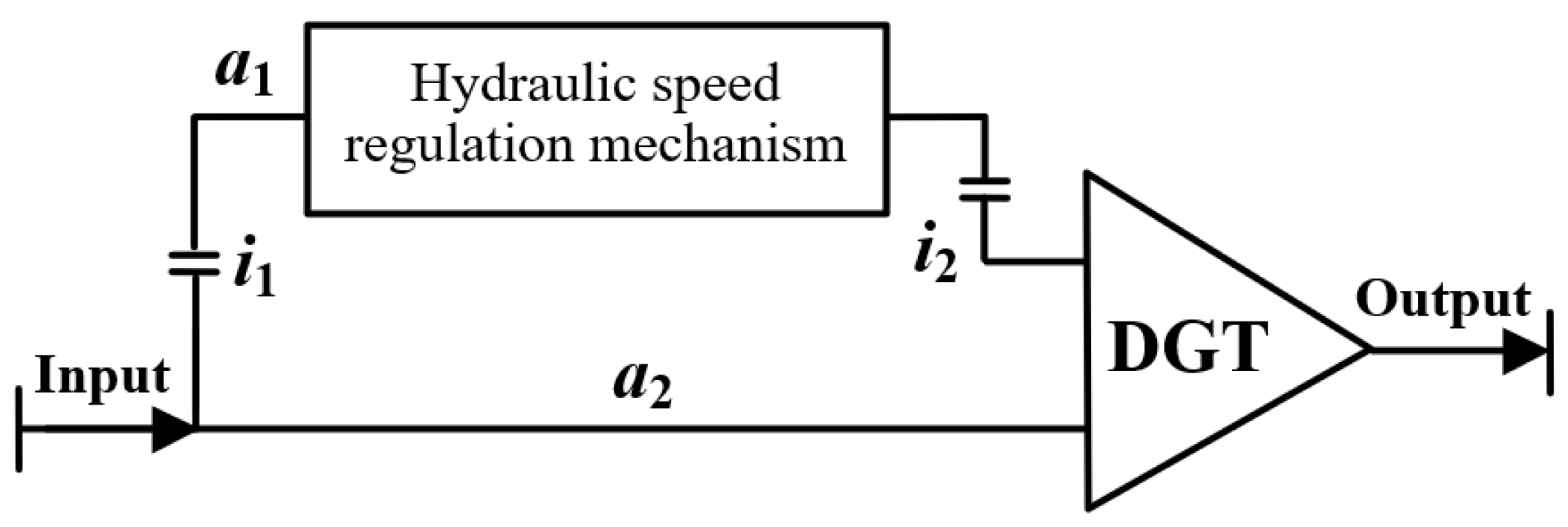
In a hydro-mechanical transmission system, the DGT can serve as both a power split device on the input side of the system and a power-combining device on the output side of the system [26]. When only one set of planetary gear exists in the system, the power-coupling form of the system can be divided into output- and input-coupling types according to the difference in the distribution position of the DGT, as shown in Figure 1.
As shown in Figure 1, both coupling forms can achieve power splitting and combining. The combining of power in the output-coupling mechanism is accomplished through a fixed-axis gear, i1. However, a fixed-axis gear has only one degree of freedom. When the rotation speed of the output shaft is zero, the rotation speed of the a1 shaft in the output-coupling mechanism is zero. At this point, there is no power transmission within the output-coupling mechanism, and the power reflux cannot be achieved. The transmission system lacks low-speed torque increase characteristics during vehicle starting. Therefore, a PHTS cannot select the output-coupling form to transmit power.
The input-coupling mechanism splits the power at the power input side and combines it using the DGT. Because the DGT has two degrees of freedom, when the output shaft rotation speed of the system is zero, the remaining two planetary gear elements that are not connected to the output shaft can still rotate in a relatively proportional relationship, creating conditions for the formation of power reflux. By controlling the hydraulic speed regulation mechanism, the power flow distribution state can be changed, and the system speed ratio can achieve active regulation. When the power reflux occurs, the system exhibits flexible transmission, preventing the engine from changing the working conditions owing to the complex environment and avoiding flameout due to a sudden increase in vehicle load. Therefore, this study selected the input-coupling form as the power-coupling form for the PHTS.
Figure 1b illustrates the power-coupling form of the PHTS and provides a basic configuration for the PHTS. This paper defines the system composed of the configuration shown in Figure 1b as split-shaft power reflux hydro-mechanical transmission system (S-PHTS). Figure 1b shows that both the a1 and a2 shafts rotate around their own axes, and the hydraulic speed regulation mechanism can be arranged on either the a2 or a1 shaft. When the hydraulic speed regulation mechanism is arranged on the a1 shaft, the PHTS forms another basic configuration, as shown in Figure 2. To facilitate the distinction, the system composed of the configuration shown in Figure 2 is defined as a combined-shaft power reflux hydro-mechanical transmission system (C-PHTS).
A comparison of Figure 1b and Figure 2 shows that, when the number of fixed-axis gears remains unchanged and only one set of planetary gear exists, the PHTS exists only in the two basic configurations shown in the S-PHTS and C-PHTS. However, the S-PHTS and C-PHTS exhibit significant differences in their transmission characteristics.

2.2. Structural Form of Hydraulic Speed Regulation Mechanism

Generally, the CLHS comprises an axial piston pump and an axial piston motor. It has the advantages of low pressure loss, high control accuracy, and high power density, all of which are suitable for high-pressure, high-flow, and high-power transmission conditions [11,27]. In HMCVT, the CLHS has been widely used as the main speed regulation component. Because construction vehicles bear large loads and operate in harsh environments, the CLHS is also justifiably retained as a hydraulic speed regulation mechanism in the PHTS.
The CLHS can control the displacement using the pump or motor. According to the difference in the regulation mode, there are three typical structural forms of the CLHS, as shown in Figure 3.
As shown in Figure 3, variable-displacement pump regulation, variable-displacement motor regulation, and variable-displacement pump–motor co-regulation are the three types of displacement regulation methods in the CLHS. According to the differences in displacement regulation methods, the CLHS includes three types of closed systems, namely, the variable displacement pump-fixed displacement motor closed-loop system (VP-FM), the fixed displacement pump-variable displacement motor closed-loop system (FP-VM), and the variable displacement pump-variable displacement motor closed-loop system (VP-VM).
In a CLHS, the displacement ratio, ε, is generally used to describe the operating status of the pump and the motor [28]. The displacement ratio is defined as the ratio of the actual displacement of the variable-displacement hydraulic components to that of the fixed-displacement hydraulic components. From the law of conservation of energy, when the volumetric efficiency is not considered, the pump–motor rotation speed and displacement ratio of the function are as follows:
ε = D V D F = n F n V
where DV and DF are the actual displacements (cm3/r) of the variable- and fixed-displacement hydraulic components, respectively, and nV and nF are the actual rotation speeds (rpm) of the variable- and fixed-displacement hydraulic components, respectively. It is worth noting that, in references related to HMCVT, the displacement ratio is often defined as the ratio of the actual displacement of the pump to that of the motor. This definition is directional and ignores the functional changes of hydraulic components, which is beneficial for simplifying HMCVT. However, the two displacement ratio definitions are essentially the same.
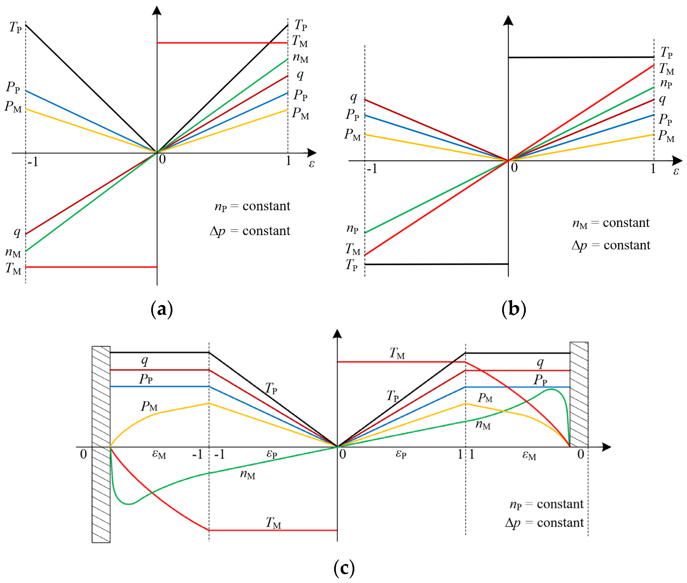
Because the pump and motor displacement regulation ranges in the CLHS are generally equal, the displacement ratio of the CLHS varies in the range of [−1, 1]. Based on Ref. [11], the partial characteristics of the CLHS are as shown in Figure 4.
Figure 4a shows a strong linear relationship between the rotation speed of the fixed-displacement motor and the displacement ratio in VP-FM. When the system pressure difference is constant, the VP-FM exhibits a constant torque output characteristic. As shown in Figure 4b, the transmission characteristics of the FP-VM, such as the rotation speed, flow rate, and power, still have strong linear relationships with the displacement ratio. The input torque of the fixed-displacement pump may remain high, even at small displacement ratios. When the pressure difference in the system is constant, the FP-VM exhibits constant torque input characteristics.
As shown in Figure 4c, when the input rotation speed of the variable-displacement pump remains constant, the output rotation speed of the VP-VM increases and the output torque rapidly decreases as the swashplate inclination of the variable displacement motor decreases. When the output torque decreases to a point where the load cannot be overcome, the motor abruptly stops rotating. Therefore, when using the VP-VM and FP-VM, it should be ensured that the variable-displacement motor remains permanently connected to the power source. The VP-VM has a larger range of displacement ratios, which can widen the speed regulation range of the transmission system. However, considering factors such as cost and efficiency, the use of the VP-VM should be minimized in non-essential scenarios.

3. Power-Flow Transmission Characteristics of PHTS

Affected by the reflux power, the power transmission mechanism of the PHTS is considerably different from those of most transmission systems. To conduct in-depth research on the PHTS, the study of the power-flow transmission characteristics of the PHTS must be prioritized.
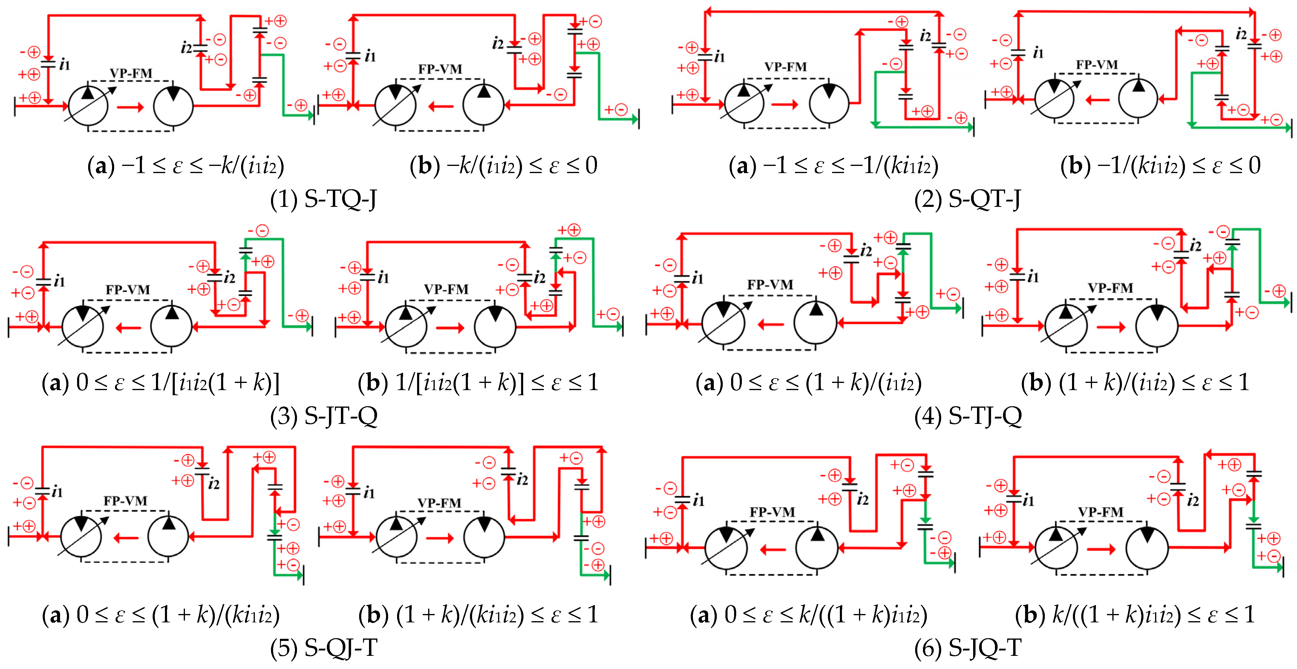
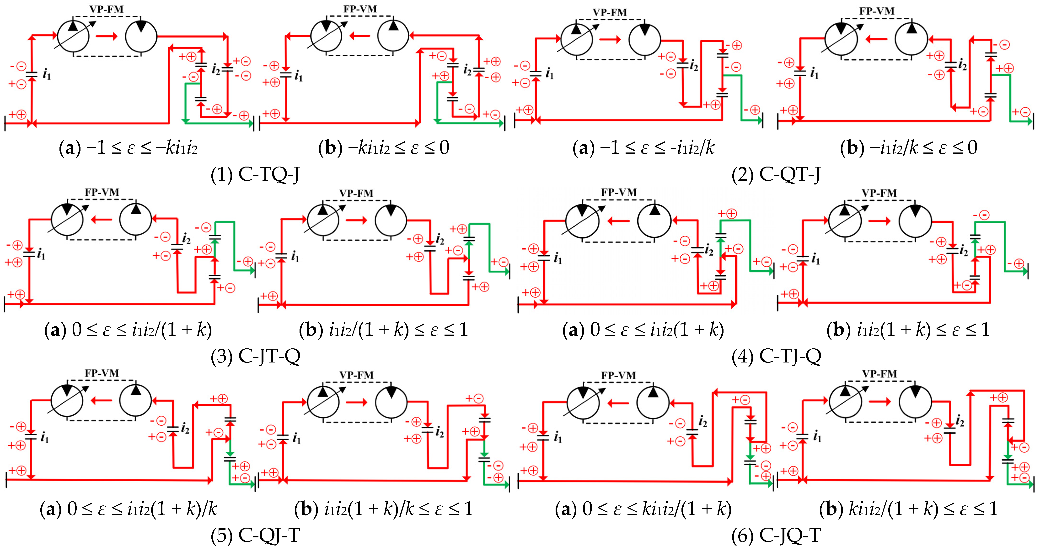
The structure of an internal–external meshing single-row planetary gear (IMSPG) is simple and compact, and it has high transmission efficiency. It is widely used in vehicle transmission systems [29]. When the PHTS uses an IMSPG as the DGT, all possible configurations and power-flow transmission states of the PHTS are as shown in Figure 5 and Figure 6.
As shown in Figure 5 and Figure 6, 12 power-flow transmission states exist for each of the S-PHTS and C-PHTS. To ensure that power can be transmitted in the desired manner, the structure form, layout method, and regulation method of the CLHS should be significantly different, even in different power-flow transmission states of the same DGT connection form. Therefore, Figure 5 and Figure 6 not only analyze the power-flow, but also, accordingly, provide 24 PHTS configurations. In the PHTS, the selection of the DGT input and output elements and the displacement ratio of the CLHS collectively determine the direction of the power flow in the system. Each configuration of the CLHS must be controlled within the specified displacement ratio range; otherwise, the configuration may be ineffective.
In each DGT connection form, the S-PHTS and C-PHTS also have two configurations with opposite output shaft rotation speeds and power-flow directions. When the displacement ratio of the configuration is allowed to be regulated to 0, the entire power is transmitted to the DGT from the mechanical path, and only a small portion of the power is refluxed via the CLHS; in contrast, when the displacement ratio of the configuration is not allowed to be regulated to 0, the entire power is transmitted to the DGT from the CLHS, and only a small portion of the power is refluxed via the mechanical path. The power-flow transmission direction of the CLHS determines the power-flow transmission direction of the PHTS. When the DGT connection form and the system output shaft rotation speed direction are the same, the reflux-power transmission directions of the S-PHTS and C-PHTS are opposite.
The power-flow transmission characteristics of the system show that the PHTS is equivalent to an energy storage mechanism, and the power input from the power source into the system can be accumulated within the system. In the process of reflux-power accumulation, the system differential pressure of the CLHS increases accordingly. When the stored power in the system reaches the level required to overcome the external resistance, the PHTS can instantaneously release the output torque that exceeds the maximum torque of the power source, thereby achieving increased torque. However, the stored power of the PHTS does not increase indefinitely. When the power stored in the PHTS increases to a certain critical value, the power loss in the system rises rapidly in the form of heat generation, leakage, friction, etc., owing to the influence of the bearings, gears, pump, and motors. When the input power of the power source is equal to the system power loss, the energy stored in the PHTS reaches a steady state, wherein the system has the maximum torque ratio.

4. Transmission Characterization of PHTS

The PHTS exists in various configurations, which may result in different performance characteristics. To further explore the PHTS and develop a new configuration suitable for construction vehicles that exhibits high transmission efficiency, wide speed regulation range, and low-speed torque increase characteristics, the transmission characteristics of the PHTS must be analyzed.

4.1. Speed Regulation Characteristics of the PHTS

The speed regulation characteristic of the PHTS is its speed ratio characteristic. For ease of calculation, the system speed ratio, ib, is defined as the ratio of the PHTS output shaft rotation speed to the input shaft rotation speed. In this paper, the S-TQ-JN configuration shown in Figure 5(1a) is used as an example to illustrate the method for calculating the speed regulation characteristics of the PHTS.
In the S-TQ-JN configuration, i1 and i2 are represented as
{ i 1 = n e / n a 1 i 2 = n a 1 / n r
where ne is the rotation speed of the power source (rpm) and na1 is the rotation speed of the a1 shaft (rpm).
From Equation (2), the rotation speed of the gear ring is expressed as
n r = n e / ( i 1 i 2 )
From Equation (1), the relationship between the sun wheel rotation speed and displacement ratio ε is
n s = ε n e
The IMSPG is a planetary gear mechanism in which the sun and ring gears rotate in opposite directions, and the rotation speed relationship of the planetary gear elements is given by
n s + k n r ( 1 + k ) n p = 0
where ns, nr, and np represent the rotation speeds (rpm) of the sun gear, ring gear, and planet carrier, respectively, and k is a characteristic parameter of the planetary gear. Generally, the value range of k is 4/3–4.
By substituting Equations (3) and (4) into Equation (5), the rotation speed of the planetary carrier, which is the rotation speed of the output shaft of the PHTS, can be determined as
n p = ( ε n e + k n e / ( i 1 i 2 ) ) / ( 1 + k )
From Equation (6), the system speed ratio ib1 of the S-TQ-JN configuration can be derived as
i b 1 = n p / n e = [ ε + ( k / i 1 i 2 ) ] / ( 1 + k )
The speed ratio calculation method for the remaining PHTS configurations is similar to that of S-TQ-JN. After clarifying the rotation speed relationship among the planetary gear elements and power source, the rotation speed of the output shaft of the PHTS can be calculated using Equation (5), thus obtaining the functional relationship between the PHTS speed ratio ib and the displacement ratio ε, as shown in Table 1.
Table 1 shows that the installation position of the CLHS and the connection form of the DGT jointly affect the speed regulation characteristics of the PHTS. To effectively compare the basic configurations of the PHTS, the configurations with the same DGT connection form in the S-PHTS and C-PHTS should have the same displacement ratio control range. Therefore, in this study, the structural parameters are selected as k = 2 and i1 = i2 = 2 for the S-PHTS and as k = 2 and i1 = i2 = 0.5 for the C-PHTS. Using these parameters as examples, the transmission characteristics of the PHTS are compared and explained. The corresponding speed regulation characteristics of the PHTS are shown in Figure 7.
Figure 7 reveals a linear relationship between the system speed ratio of the PHTS and the displacement ratio of the CLHS. The PHTS possesses the largest speed regulation range when the sun wheel is connected to the output shaft of the system. In contrast, it has the smallest speed regulation range with the planetary carrier as the output shaft. If the displacement ratio is sufficiently large, the speed ratios of the same type of configurations will be equal at a certain displacement ratio.

4.2. Transmission Efficiency Characteristics of the PHTS

4.2.1. Calculation of the Transmission Efficiency

A PHTS is a typical closed-loop planetary transmission system, and the transmission form of the power flow is complex. To accurately reflect the loss of power within the PHTS, the transmission efficiency of the PHTS is calculated using the engaging power method [30]. Considering the efficiency calculation for S-TQ-JN as an example, the rotation speed relationship possessed by the two transmission paths of this configuration is
{ i sI = n s / n e = ε i rI = n r / n e = 1 / i 1 i 2
where I represents the input shaft of the PHTS.
The conversion speed ratios i p s r and i p r s are defined as follows:
{ i ps r = ( n p n r ) / ( n s n r ) i pr s = ( n p n s ) / ( n r n s )
Incorporating Equation (5) into Equation (9) reveals that
i ps r = 1 / ( 1 + k ) ; i pr s = k / ( 1 + k )
From Equations (8) and (10), i p I r and i p I s can be derived.
i pI r = i ps r i sI = ε / ( 1 + k )
i pI s = i pr s i rI = k / ( ( 1 + k ) i 1 i 2 )
For ε ∈ [−1, −k/(i1i2)], i p I r i p I s < 0 and | i p I r | > | i p I s |. The transmission efficiency ηTJ of S-TQ-JN can be expressed as
η TJ = 1 / [ 1 + | 1 / i b 1 | [ | i pI s i pr s i pI | φ X + | i pI s | ( 1 η g ) + | i pI r | ( 1 η P-M ) / η P-M ] ]
where φX is the transmission loss coefficient of the DGT when the planetary carrier is fixed, ηg is the total transmission efficiency of fixed-axis gears i1 and i2, and ηP-M is the transmission efficiency of the CLHS.
In this study, a CLHS composed of a variable displacement axial piston pump and a fixed-displacement axial piston motor (rated displacement of 125 cm3/r) is used as an example. The interpolation method was used to fit the transmission efficiency, and the functional relationship among the transmission efficiency of the CLHS, system differential pressure, and displacement ratio was determined.
η P-M = j = 0 4 i = 0 j A ε i Δ p j i
The fitted coefficient matrix is the following:
A = [ A 1 A 2 A 3 ] T { A 1 = [ 0.652 0.01319 4.471 9.645 × 10 5 1.279 ] A 2 = [ 10.71 3.063 × 10 7 2.174 × 10 5 5.897 × 10 3 12.66 ] A 3 = [ 3.537 × 10 10 3.56 × 10 8 2.02 × 10 6 4.484 × 10 3 5.694 ]
where A is a polynomial coefficient matrix and Δp is the system differential pressure (bar).
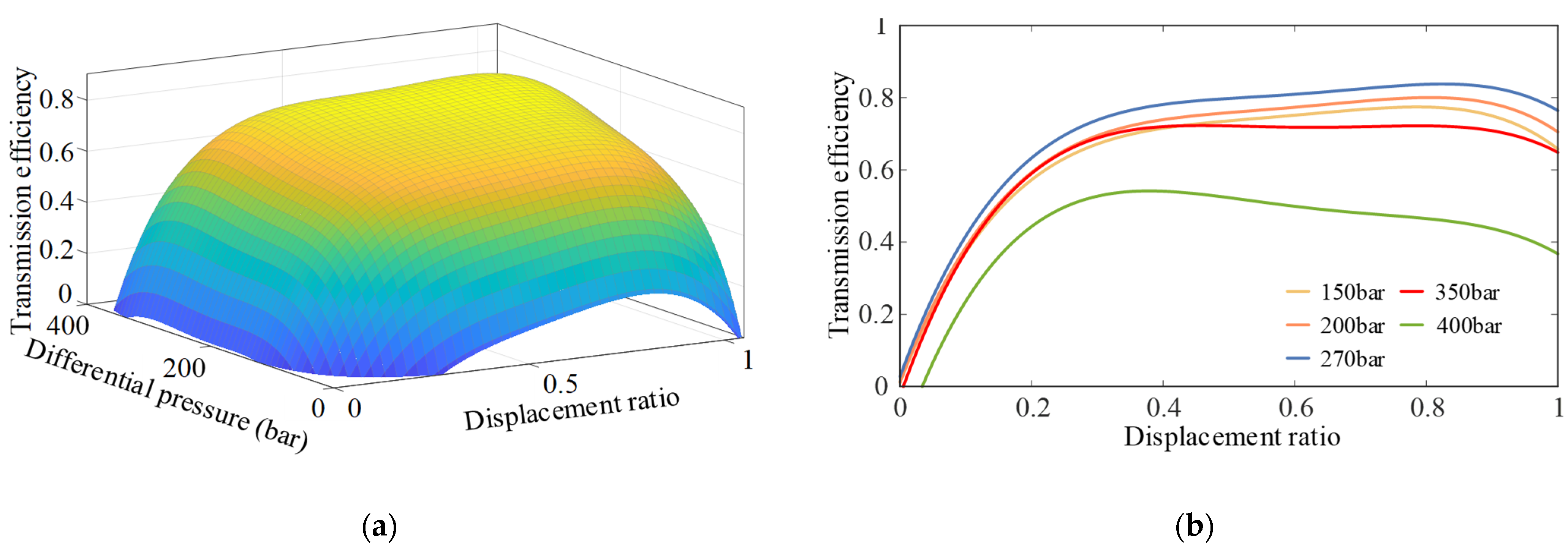
Based on Equation (14), the transmission efficiency characteristics of the CLHS are as shown in Figure 8.
As shown in Figure 8, with the increasing pressure difference, the transmission efficiency of the CLHS first increases and then decreases. When the pressure difference reaches 400 bar, the transmission efficiency of the CLHS does not exceed 53%. Therefore, in the design process, the maximum pressure difference across the CLHS must not exceed 350 bar. Within the main operational range, the CLHS achieves its highest efficiency at Δp = 270 bar, whereas its efficiency is lowest at Δp = 350 bar.
Ref. [31] shows that when the rated displacements are equal, the displacement regulation method has a minimal effect on the transmission efficiency of the CLHS. Therefore, Equation (14) was uniformly used as the efficiency model of the CLHS in the calculation of the PHTS configuration. Referring to the efficiency calculation methods for S-TQ-JN, the transmission efficiency characteristics of the remaining PHTS configurations can be calculated as listed in Table 2.
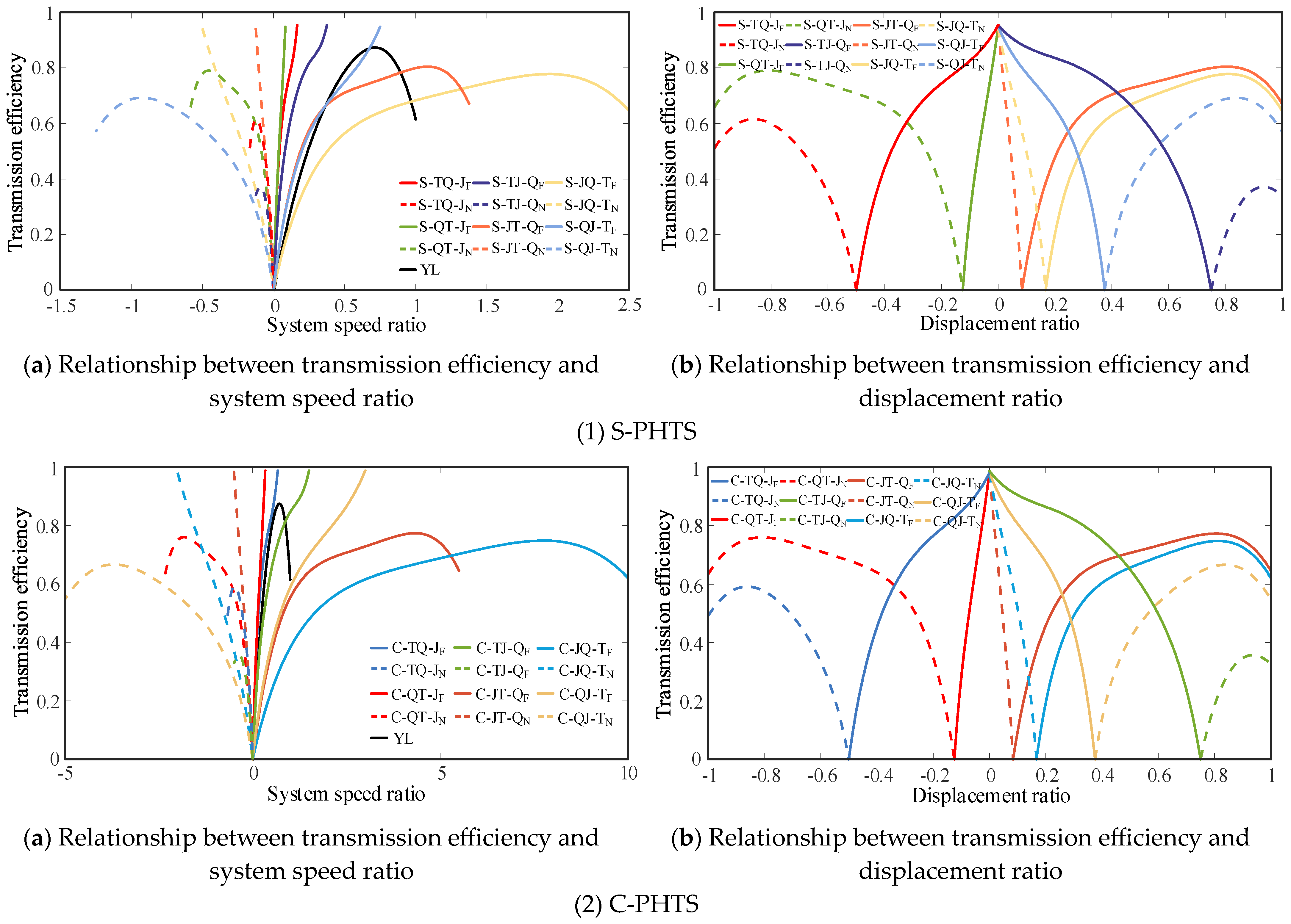
The calculations in Table 1 and Table 2 reveal that a correlation exists between the transmission efficiency of the PHTS and the displacement ratio. The efficiency characteristic curve of the PHTS is shown in Figure 9.
As shown in Figure 9, when the displacement ratio control range of the configuration does not include zero, that is, the rotation speed of the fixed-displacement hydraulic component cannot be adjusted to 0, no purely mechanical transmission condition exists in the configuration, and the transmission efficiency shows a trend of increasing and then decreasing with the change in the speed ratio or displacement ratio. In high-speed driving conditions, this type of configuration is not conducive to improving the transmission efficiency of the vehicle. Additionally, the transmission efficiency of this configuration is generally low, and compared with the torque converter, it has no obvious efficiency advantage. Therefore, the relevant configurations whose displacement ratio control range does not include zero are non-advantageous and should be avoided in vehicle transmission systems.
When the DGT connection forms and the displacement ratio control ranges of the S-PHTS and C-PHTS are identical, the efficiency characteristic curves of the S-PHTS and C-PHTS exhibit similar trends. To clearly show the efficiency difference between the S-PHTS and C-PHTS and to study the effect of structural forms on the transmission efficiency, the efficiency characteristics of the two basic configurations must be compared.

4.2.2. Efficiency Comparison between C-PHTS and S-PHTS

Because the C-PHTS and S-PHTS have different configurations, their power loss mechanisms should be different. As shown in Figure 5 and Figure 6, both C-PHTS and S-PHTS have two reflux transmission forms. The power loss mechanism of the PHTS in different reflux transmission forms is shown in Figure 10.
As shown in Figure 10, when the PHTS transmits power in hydraulic–mechanical reflux transmission form, the instantaneous system input power and reflux power are all transmitted to the DGT via the hydraulic path; when the PHTS transmits power in mechanical–hydraulic reflux transmission form, only the reflux power is transmitted via the hydraulic path. Because the reflux power is only a part of the total input power of the DGT and the transmission efficiency of the CLHS is considerably lower than that of gears or mechanical transmission shafts, the mechanical–hydraulic reflux transmission form of the PHTS is more conducive to improving transmission efficiency.
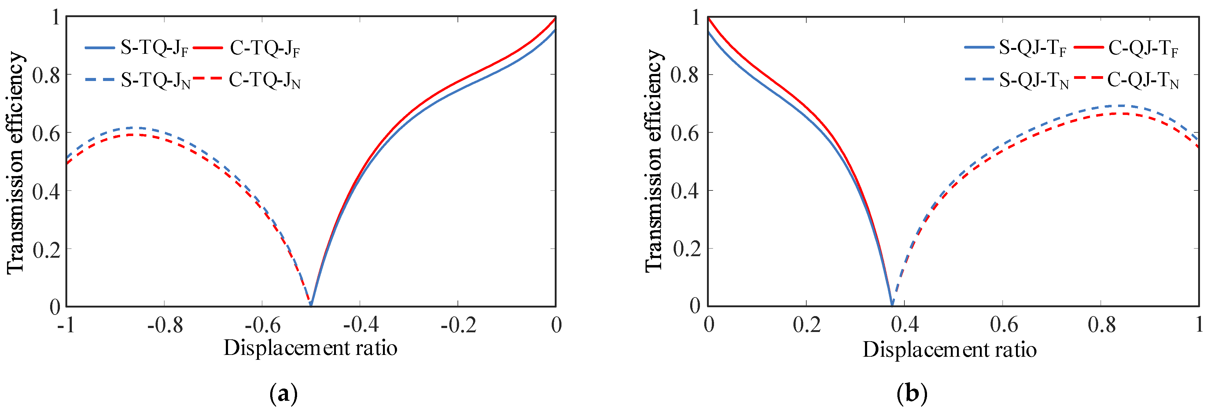
To compare the efficiency characteristics of the C-PHTS and S-PHTS, this study considers eight PHTS configurations in the two connection forms of TQ-J and QJ-T as examples for analysis, as shown in Figure 11.
Figure 5 and Figure 6 show that, among the eight configurations shown in Figure 11, S-TQ-JF, C-TQ-JF, S-QJ-TF, and S-QJ-TF transmit power through the mechanical–hydraulic reflux transmission form, whereas S-TQ-JN, C-TQ-JN, S-QJ-TN, and S-QJ-TN transmit power through the hydraulic–mechanical reflux transmission form. Comparing the efficiency curves of the aforementioned configurations reveals that, for the same DGT connection form and displacement ratio control range, the C-PHTS configuration has higher transmission efficiency when the PHTS is configured in the mechanical–hydraulic reflux transmission form. Conversely, the S-PHTS configuration exhibits higher transmission efficiency when the PHTS is configured in the hydraulic–mechanical reflux transmission form. The closer the system speed ratio is to zero, the smaller the difference in efficiency between the C-PHTS and S-PHTS becomes. Note that, while Figure 11 only randomly presents two types of DGT connection forms, the aforementioned rules are valid for any DGT connection form of the PHTS.
Figure 10(1b,2b) show that, in the mechanical–hydraulic reflux transmission form, the power losses Pls1 and Plc1 in the S-PHTS and C-PHTS, respectively, can be expressed as follows.
{ P ls 1 = P tm P tm η g + P tm η g b P tm η P-M b η g P lc 1 = P tm b P tm η P-M b η g
where Ptm is the total power input to the mechanical transmission path (kW) and b is the power reflux ratio, defined as the ratio of the reflux power to the total power input to the DGT, where b ∈ [0, 1].
The difference Pd1 in power loss between the two basic configurations is
P d 1 = | P ls 1 P lc 1 | = P tm ( 1 η g ) ( 1 b )
Equation (16) shows that Pd1 is negatively correlated with ηg and b. In the mechanical–hydraulic reflux transmission form, as the absolute value of the displacement ratio |ε| becomes larger, it results in a system speed ratio closer to zero, a smaller output power of the PHTS, and a larger b. When the PHTS system speed ratio stabilizes at zero, all the power contributes to the power reflux, i.e., b = 1. Therefore, |ε| is positively correlated with b, Pd1 is negatively correlated with |ε|, and C-PHTS has higher transmission efficiency.
Similarly, Figure 10(1a,2a) show that, in the hydraulic–mechanical reflux transmission form, the power losses Pls2 and Plc2 in the S-PHTS and C-PHTS, respectively, can be expressed as follows.
{ P ls 2 = P th P th η P-M + P th η P-M b P th η P-M b η g P lc 2 = P th P th η P-M η g
where Pth is the total power input to the hydraulic transmission path (kW).
The difference Pd2 in power loss between the two basic configurations is calculated as
P d 2 = | P ls 2 P lc 2 | = P th η P-M ( 1 η g ) | b 1 |
Equation (18) shows that Pd2 is not only negatively correlated with ηg and b, but also correlated with the transmission efficiency of the CLHS. In the hydraulic–mechanical reflux transmission form, the smaller |ε| is, the closer the PHTS system speed ratio is to zero, and the larger b becomes. When the speed ratio is zero, all the power contributes to the power reflux, i.e., b = 1. Therefore, |ε| is negatively correlated with b, Pd1 is positively correlated with |ε|, and the S-PHTS has higher transmission efficiency.

4.3. Low-Speed Torque Increase Characteristics of the PHTS

The torque ratio is the main index that reflects the low-speed torque increase characteristic of a PHTS. When the system configuration and structural parameters are determined, the torque ratio of the PHTS depends on the displacement ratio and transmission efficiency of the CLHS. Considering the S-TQ-JN configuration as an example, the relationship between the rotation speed of the DGT input element and that of the power source is
{ n s = ε n e n r = n e / ( i 1 i 2 )
Based on Figure 5(1a), the power transmission relationship within the S-TQ-JN can be expressed as
( | P r | η g + | P e | ) η P-M = | P s |
where Pr is the power transmitted by the gear ring (kW), Pe is the input power of the power source (kW), and Ps is the power transmitted by the sun wheel (kW).
Incorporating Equation (19) into Equation (20) yields
| T r | i 1 i 2 η g + | T e | = | ε | η P-M | T s |
where Ts, Tr, and Tp represent the torques (Nm) of the sun gear, ring gear, and planet carrier, respectively.
The torque relationship among the gear ring, planetary carrier, and sun wheel of the DGT is given by
{ | T r | = k | T s | | T p | = ( 1 + k ) | T s |
Incorporating Equation (22) into Equation (21) yields the expression for the torque ratio of S-TQ-JN, as follows:
K = | T j | / | T e | = ( 1 + k ) η P-M i 1 i 2 / [ | ε | i 1 i 2 k η g η P-M ]
Based on the above calculations, the torque ratios for all PHTS configurations can be expressed as shown in Table 3.
Table 2 and Table 3 show that both the torque and system speed ratios of the PHTS have a functional relationship with ε when the structural parameters of the system are determined. Therefore, the relationship between the torque and system speed ratios can be established by ε. Figure 12 shows the relationship curves of the torque ratios for the PHTS configurations that transmit power in the mechanical–hydraulic reflux transmission form.
Figure 12 shows that, when the DGT connection form and the displacement ratio control range are identical for the S-PHTS and C-PHTS, the S-PHTS has a larger torque ratio but a relatively narrow speed regulation range, whereas the C-PHTS has a smaller torque ratio but a wider speed regulation range. When the rotation speed of the input shaft is constant and the load is sufficiently large, the system speed ratio of the PHTS is 0. In this condition, the system does not output power externally; all the power is stored in the form of reflux power, and the reflux power in the system can reach the maximum value. At this point, the law of conservation of energy states that the output shaft of the system can output the maximum torque and that a maximum torque ratio exists in the PHTS.
Although the two basic configurations share the same transmission principle and both have a maximum torque ratio when the system speed ratio is 0, differences exist in the calculation methods for the maximum torque ratio of the S-PHTS and C-PHTS owing to the influence of the structural form. This paper considers S-TQ-JF and C-TQ-JF as examples for illustration.
Table 3 shows that the torque ratio of S-TQ-JF can be expressed as follows:
K SJF = ( 1 + k ) η g i 1 i 2 k | ε | i 1 i 2 η g η P-M
Figure 6 and Table 1 show that the control range of the displacement ratio ε of C-TQ-JF is [−k/i1i2, 0]. When ε = −k/i1i2, the system speed ratio of S-TQ-JF is 0. At this time, the torque ratio of S-TQ-JF can be expressed as
K SJF = ( 1 + k ) η g [ k / ( i 1 i 2 ) ] ( 1 η g η pm ) = ( 1 + k ) η g | ε | max ( 1 η g η pm )
where ηpm is the transmission efficiency of the CLHS when the displacement ratio of the CLHS is maximum or minimum (|ε| = |ε|max).
Equation (25) shows that KSJF is maximum when the determinant |ε|max (1 − ηgηpm) is minimum. The maximum torque ratio of S-TQ-JF depends on k, i1i2, and ηpm. Reference [32] states that, in vehicle transmission systems, the transmission ratio of a single-stage external cylindrical gear train is generally between 0.6 and 2.8. Therefore, when calculating the maximum torque ratio of the S-PHTS, the range of i1i2 should be limited to [0.36, 7.84].
Based on Table 3, the torque ratio of C-TQ-JF is
K CJF = ( 1 + k ) k [ 1 ( | ε | / ( k i 1 i 2 ) ) η g η P-M ]
The control range of the displacement ratio ε for C-TQ-JF is [−ki1i2, 0]. When ε = −ki1i2, the system speed ratio of C-TQ-JF is 0. At this point, the torque ratio of C-TQ-JF can be expressed as
K CJF = ( 1 + k ) k ( 1 η g η P-M )
The CLHS efficiency model described in Equation (14) indicates that the CLHS has a maximum transmission efficiency ηpmmax (ηpmmax = 0.837) when the pressure difference is 270 bar and the displacement ratio is 0.85. Accordingly, the maximum torque ratio of C-TQ-JF can be calculated as
K CJF max = ( 1 + k ) k ( 1 η g η p m max ) = ( 1 + k ) 0.196 k
To sum up, when k is a constant, the maximum torque ratio of the C-PHTS is only related to the maximum transmission efficiency of the CLHS; however, the maximum torque ratio of the S-PHTS is related to the displacement ratio and transmission efficiency of the CLHS in the vehicle starting condition, and more factors must be considered during design optimization. Referring to the previous calculation process, the maximum torque ratio for the configurations described in Figure 12 can be calculated for different k values. The calculation results are shown in Table 4.
From Table 4, the maximum torque ratio of C-QJ-TF and C-JQ-TN is relatively small. For most sets of structural parameters, these two configurations cannot meet the requirements for use in construction vehicles and have limited optimization potential. Therefore, the C-QJ-TF and C-JQ-TN configurations are not suitable for construction vehicles.

5. Feasibility Analysis of the PHTS

The analysis of PHTS characteristics reveals that, among the configurations listed in Table 4, the ten configurations, except C-QJ-TF and C-JQ-TN, have good efficiency characteristics and large torque ratios. To accurately evaluate the aforementioned ten configurations and clearly explain the influence of configuration parameters on transmission characteristics, the upper limit of the system speed ratio of the configurations must be analyzed.
Table 1 shows that all configurations listed in Table 4 have speed ratio upper limits when the displacement ratio is 0. Among them, the speed ratio upper limit of the C-PHTS is related only to k, whereas that of the S-PHTS is related to both k and i1i2. Therefore, when calculating the speed ratio upper limit of the S-PHTS, the range of i1i2 values must be considered.
Considering S-QT-JF as an example, the control range of the displacement ratio ε of the configuration is [−1/(ki1i2), 0]. Because |ε| 1, the numerical relationship between k and i1i2 is
i 1 i 2 [ 1 / k , + ] [ 0.36 , 7.84 ]
The maximum speed ratio upper limit ibmax for S-QT-JF can be expressed as
i b max = 1 i 1 i 2 ( 1 + k )
ibmax can be calculated by incorporating the value of k into Equation (30).
k = { 1.5 2 3 4 i 1 i 2 { [ 0.66 , 7.84 ] [ 0.5 , 7.84 ] [ 0.36 , 7.84 ] [ 0.36 , 7.84 ] i b max = { 0.61 0.66 0.69 0.55
Note that, in the form of mechanical–hydraulic reflux transmission, the speed ratio upper limit |ib| of the S-PHTS is positively related to |ε|max. When |ε|max = 1, the S-PHTS has the maximum speed ratio upper limit. The maximum speed ratio upper limits of the aforementioned ten advantageous configurations are shown in Table 5.
Table 5 shows that S-TQ-JF and C-QT-JF have the smallest speed ratio upper limits. This not only results in a narrow high-efficiency zone of the system, but is also detrimental to improving vehicle comfort. Therefore, this study concludes that the S-TQ-JF and C-QT-JF configurations do not possess structural advantages.
Because the planet carrier of C-TJ-QF is directly connected to the power source and the rated rotation speed of diesel engines used in construction vehicles is generally around 2000 rpm, when a vehicle is equipped with C-TJ-QF, the maximum rotation speed of the sun wheel connected to the hydraulic path is essentially above 5000 rpm. When k is increased, the rotation speed of the sun gear further increases and may even exceed 10,000 rpm. Likewise, S-JT-QN has similar problems. While both C-TJ-QF and S-JT-QN exhibit good transmission characteristics, considering the actual operating conditions of construction vehicles, the cost, and the reliability, the practicality of these two configurations is believed to be relatively low.
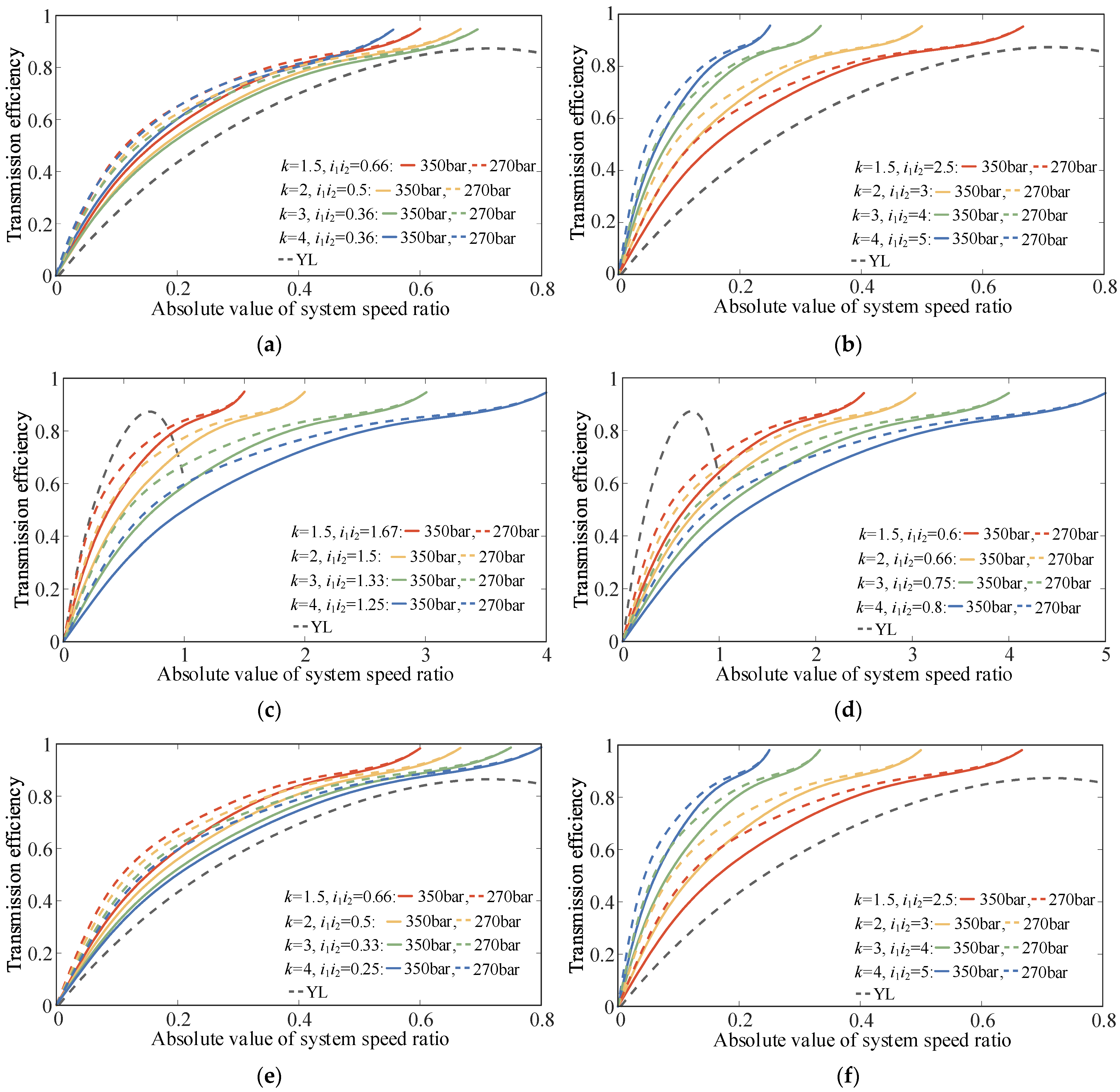
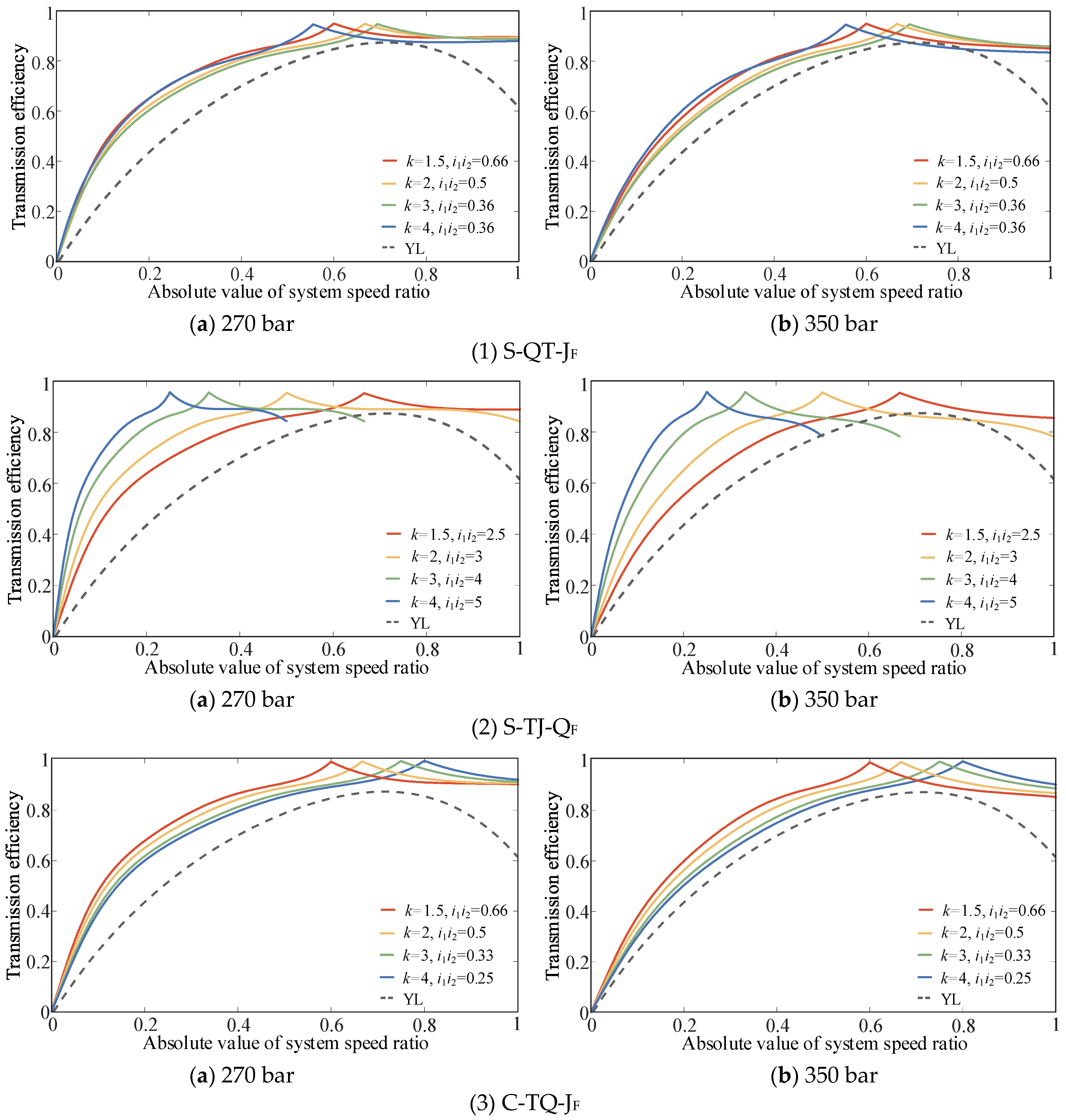
To illustrate the validity of the configuration and determine the optimal configuration, this study considers as an example the large load operating conditions where the pressure difference of the CLHS is stable at 270 and 350 bar. The efficiency characteristics of S-QT-JF, S-TJ-QF, S-QJ-TF, S-JQ-TN, C-TQ-JF, and C-JT-QN were compared with those of the torque converter, as shown in Figure 13.
Figure 13 shows that k, i1i2, and ηP-M significantly impact the transmission efficiency of the PHTS. Compared with the torque converter, S-QJ-TF and S-JQ-TN exhibit no efficiency advantages within the same speed ratio range. To enhance the transmission efficiency, these configurations must be used in series with a reducer. In addition, owing to their structural form, S-QJ-TF and S-JQ-TN have extremely high requirements for the rated power of the CLHS, which considerably increases the overall cost. Therefore, S-QJ-TF and S-JQ-TN are also considered to have no practical value for use.
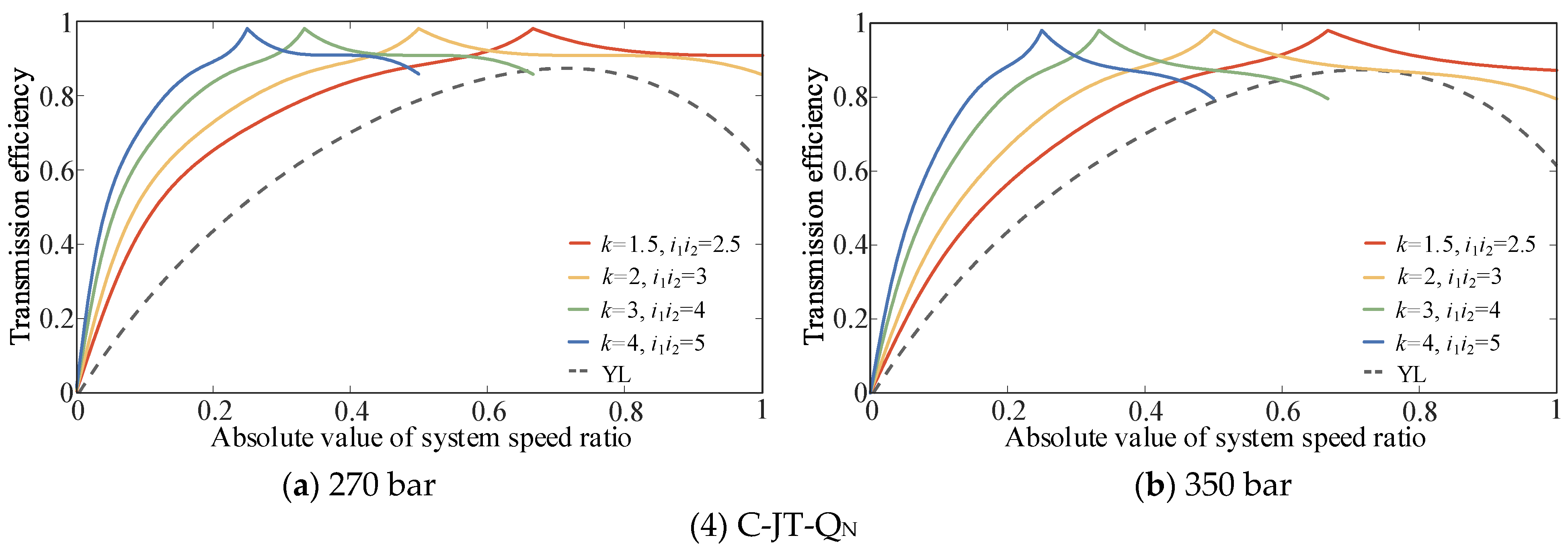
The transmission efficiencies of S-QT-JF, S-TJ-QF, C-TQ-JF, and C-JT-QN are relatively high. Even at the lowest efficiency of the CLHS, these four configurations have higher transmission efficiencies within the same speed ratio range compared with the torque converter. However, the speed ratio upper limits of these configurations remain small, and there is a problem of narrow high-efficiency areas. Therefore, simply applying the reflux transmission mode to the transmission system is insufficient. To widen the high-efficiency range of the system without increasing the number of vehicle gears, it is necessary to expand the CLHS displacement ratio control range (switching to bidirectional CLHS) in practical applications and use the split transmission mode to increase the system speed ratio’s upper limit. Considering as an example the advantageous configurations shown in Figure 13, the efficiency characteristics of the configurations after expanding the CLHS displacement ratio control range are as shown in Figure 14.
Figure 14 shows that expanding the displacement ratio control range of the CLHS can effectively widen the high-efficiency ranges of S-QT-JF, S-TJ-QF, C-TQ-JF, and C-JT-QN. The reflux transmission mode is applied to the starting stage of the vehicle to avoid engine stalling and increase the torque at low speeds, whereas the split transmission mode is applied to the high-speed driving conditions to widen the high-efficiency range of the system. The orderly combination of reflux and split transmission modes can ensure the power performance of construction vehicles without increasing the number of vehicle gears, improve the transmission efficiency, widen the high-efficiency range, and compensate for the shortcomings of the low transmission efficiency of the torque converter.

6. Conclusions

To significantly improve the transmission efficiency of the vehicle while ensuring the power performance in order to enhance the construction vehicle’s performance, this study applies the power reflux hydro-mechanical transmission system (PHTS) to the starting of a construction vehicle and investigates the PHTS configurations. By analyzing the internal relationship between the configuration and the power-flow transmission form, transmission characteristics, and energy loss mechanism, the following conclusions can be drawn:
(1) The PHTS exhibits a similar transmission performance to the hydrodynamic transmission system, which not only ensures that the engine maintains high-speed operation at zero vehicle speed and avoids stalling, but also improves the vehicle’s ability to start and to overcome obstacles. Reasonable configurations can enable the PHTS to significantly improve the efficiency of the construction vehicle transmission system while ensuring power performance. Expanding the displacement ratio control range of the hydraulic speed regulation mechanism and combining the power reflux transmission mode with the power split transmission mode in an orderly manner can widen the high-efficiency range of the vehicle transmission system without increasing the number of vehicle gears, and can compensate for the shortcomings of the low transmission efficiency of the torque converter.
(2) When the connection forms of the DGT are identical, the C-PHTS exhibits higher transmission efficiency in the mechanical–hydraulic reflux transmission form, whereas the S-PHTS exhibits higher transmission efficiency in the hydraulic–mechanical reflux transmission form. Although the S-PHTS always shows a larger torque ratio and speed ratio upper limit compared with the C-PHTS, it has a higher power requirement for the CLHS owing to the influence of its structural form.
(3) From the analysis results of PHTS transmission characteristics, the four configurations, i.e., S-QT-JF, S-TJ-QF, C-TQ-JF, and C-JT-QN, are considered to have better transmission characteristics and to be suitable for construction vehicles.
This paper proposes a new method of using a hydrostatic external reflux transmission system to replace a hydrodynamic internal reflux transmission system, and provides a guide for a new research direction in the field of hydro-mechanical composite transmission. However, it is limited by page length restrictions for the article. This paper has not yet discussed issues such as matching, optimization, and control methods between PHTS and the vehicle. In the future, based on real prototype vehicles, we plan to further analyze the cooperative operation methods between PHTS and the shifting mechanism, research the design methods for hydrostatic reflux automatic transmission, and explore the dynamic characteristics of PHTS under various starting conditions so as to lay the foundation for the development of control strategies.

Author Contributions

Conceptualization, D.S.; methodology, J.W. (Jiezhong Wang); software, J.W. (Jianhua Wang) and G.L.; validation, D.S. and J.W. (Jianhua Wang); formal analysis, J.W. (Jiezhong Wang); investigation, D.S.; data curation, J.W. (Jiezhong Wang); writing—original draft preparation, J.W. (Jiezhong Wang); writing—review and editing, J.W. (Jianhua Wang); visualization, G.L.; supervision, D.S.; project administration, D.S. All authors have read and agreed to the published version of the manuscript.

Funding

This study was supported by Jiangsu Province Innovation and Entrepreneurship Team Project (grant no. JSSCTD202239), Fundamental Research Funds for the Central Universities (grant no. 2022CDJDX-004), Chongqing Science and Technology Innovation Major R&D Project (grant no. CSTB2022TIAD-STX0005), and Jiangsu Province Special Fund for Transformation of Scientific and Technological Achievements (grant no. BA2022033).

Data Availability Statement

Data are contained within the article.

Acknowledgments

The authors would like to thank the editors and the anonymous reviewers for their comments and suggestions.

Conflicts of Interest

The authors declare no competing interests.

Nomenclature

HMTSHydro-mechanical transmission system
PHTSPower reflux hydro-mechanical transmission system
S-PHTSSplit-shaft power reflux hydro-mechanical transmission system
C-PHTSCombined-shaft power reflux hydro-mechanical transmission system
CLHSClosed-loop hydraulic system
DGTDifferential gear train
PSTMPower split transmission mode
PRTMPower reflux transmission mode
εDisplacement ratio
nVActual rotation speed of the variable-displacement hydraulic components, rpm
nFActual rotation speed of the fixed-displacement hydraulic components, rpm
VP-FMVariable displacement pump-fixed displacement motor closed-loop system
FP-VMFixed displacement pump-variable displacement motor closed-loop system
neRotation speed of the power source, rpm
nsRotation speed of the sun wheel, rpm
nrRotation speed of the gear ring, rpm
npRotation speed of the planetary carrier, rpm
i1,i2Transmission ratios of fixed-axis gears
kCharacteristic parameter of the planetary gear
ibSystem speed ratio of the PHTS
iabRatio of the rotation speed of elements a and b in the PHTS
i b c a Ratio of the rotation speed of elements b and c relative to element a in the PHTS
ηP-MTransmission efficiency of the CLHS
ΔpSystem differential pressure of the CLHS
φXPower loss coefficient of the DGT when the planetary carrier is fixed
ηgTotal transmission efficiency of fixed-axis gears i1 and i2
Pls1Power loss in the S-PHTS in the mechanical–hydraulic reflux transmission form, kW
Plc1Power loss in the C-PHTS in the mechanical–hydraulic reflux transmission form, kW
PtmTotal power input to the mechanical transmission path in the mechanical–hydraulic reflux transmission form, kW
Pls2Power loss in the S-PHTS in the hydraulic–mechanical reflux transmission form, kW
Plc2Power loss in the C-PHTS in the hydraulic–mechanical reflux transmission form, kW
PthTotal power input to the hydraulic transmission path in the hydraulic–mechanical reflux transmission form, kW
bPower reflux ratio, defined as the ratio of the reflux power to the total power input to the DGT
Pd1Difference in power loss between the S-PHTS and C-PHTS in the mechanical–hydraulic reflux transmission form, kW
Pd2Difference in power loss between the S-PHTS and C-PHTS in the hydraulic–mechanical reflux transmission form, kW
PrPower transmitted by the gear ring, kW
PeInput power of the power source, kW
PsPower transmitted by the sun wheel, kW
TsTorque of the sun wheel, Nm
TrTorque of the gear ring, Nm
TpTorque of the planetary carrier, Nm
KTorque ratio, expressed as the ratio of the output torque to the input torque of the system
ηpmTransmission efficiency of the CLHS when the displacement ratio of the CLHS is maximum or minimum (|ε| = |ε|max)
ηpmmaxMaximum transmission efficiency of the CLHS

References

  1. Li, C.; Meng, F.; Xi, J.; Zhai, Y. Starting shift control of heavy-duty automatic transmissions based on the optimal trajectory of turbine speed. Mech. Syst. Signal Process. 2019, 126, 490–504. [Google Scholar] [CrossRef]
  2. Karaoglan, M.U.; Vatansever, Y.; Kuralay, N.S. Simulation of 8 × 8 heavy duty truck for evaluating effects of torque converter characteristics on vehicle performance. Mechanika 2018, 24, 232–239. [Google Scholar] [CrossRef]
  3. Xiong, P.; Chen, X.; Sun, H.; Zhong, J.; Wu, L.; Gao, H. Effect of the blade shaped by Joukowsky airfoil transformation on the characteristics of the torque converter. Proc. Inst. Mech. Eng. Part D J. Automob. Eng. 2021, 235, 3314–3321. [Google Scholar]
  4. Kim, B.S.; Ha, S.B.; Lim, W.S.; Cha, S.W. Performance estimation model of a torque converter part I: Correlation between the internal flow field and energy loss coefficient. Int. J. Automot. Technol. 2008, 9, 141–148. [Google Scholar] [CrossRef]
  5. Do, H.T.; Park, H.G.; Ahn, K.K. Application of an adaptive fuzzy sliding mode controller in velocity control of a secondary controlled hydrostatic transmission system. Mechatronics 2014, 24, 1157–1165. [Google Scholar] [CrossRef]
  6. Guo, X.; Vacca, A. Advanced design and optimal sizing of hydrostatic transmission systems. Actuators 2021, 10, 243. [Google Scholar] [CrossRef]
  7. Comellas, M.; Pijuan, J.; Nogues, M.; Roca, J. Efficiency analysis of a multiple axle vehicle with hydrostatic transmission overcoming obstacles. Veh. Syst. Dyn. 2018, 56, 55–77. [Google Scholar] [CrossRef]
  8. Yu, J.; Dong, X.; Song, Y.; Zhang, Y.; Zhang, H.; Yang, X.; Xu, Z.; Liu, Y. Energy efficiency optimization of a compound coupled hydro-mechanical transmission for heavy-duty vehicles. Energy 2022, 252, 123937. [Google Scholar] [CrossRef]
  9. Savaresi, S.M.; Taroni, F.L.; Previdi, F.; Bittanti, S. Control system design on a power-split CVT for high-power agricultural tractors. IEEE/ASME Trans. Mechatron. 2004, 9, 569–579. [Google Scholar] [CrossRef]
  10. Cao, F.Y.; Zhou, Z.L.; Zhao, H.J. Design of steering wheel control system of tracked vehicle of hydro-mechanical differential turning. Adv. Mater. Res. 2012, 472–475, 753–756. [Google Scholar]
  11. Liu, X. Vehicle Transmission System Analysis; National Defense Industry Press: Beijing, China, 1998. [Google Scholar]
  12. Rossetti, A.; Macor, A. Multi-objective optimization of hydro-mechanical power split transmissions. Mech. Mach. Theory 2013, 62, 112–128. [Google Scholar] [CrossRef]
  13. Pettersson, K.; Heybroek, K.; Mattsson, P.; Krus, P. A novel hydromechanical hybrid motion system for construction machines. Int. J. Fluid Power 2017, 18, 17–28. [Google Scholar] [CrossRef]
  14. Liu, F.; Wu, W.; Hu, J.; Yuan, S. Design of multi-range hydro-mechanical transmission using modular method. Mech. Syst. Signal Process. 2019, 126, 1–20. [Google Scholar] [CrossRef]
  15. Wu, W.; Luo, J.; Wei, C.; Liu, H.; Yuan, S. Design and control of a hydro-mechanical transmission for all-terrain vehicle. Mech. Mach. Theory 2020, 154, 104052. [Google Scholar] [CrossRef]
  16. Troin, P.E.; Gostomski, V.G. Application Considerations with the Cummins Sundstrand DMT-25 Hydromechanical Transmission; SAE Technical Paper 750732; SAE International: Warrendale, PA, USA, 1975. [Google Scholar]
  17. Brenninger, M.M. Fendt Vario CVT in Agricultural Tractors; SAE Technical Paper 4205; SAE International: Warrendale, PA, USA, 2007. [Google Scholar]
  18. Wu, Q. 800 Vario Series Continuously Variable New Tractors from FENDT Company. Tract. Farm Transp. 2016, 43, 6–11. [Google Scholar]
  19. Pohlenz, J.; Gruhle, W.D. The ECCOM continuously variable hydrostatic-variable power-split transmission for use in tractors. VDI Berichte 2001, 1592, 451–468. [Google Scholar]
  20. Messenger, B. Hydrostatic transmission designed for compact mobile applications. Diesel Prog. Int. Ed. 2003, 22, 28. [Google Scholar]
  21. Nagao, T.; Ichiryu, K.; Masuzawa, K. Development of SATV [Super All Terrain Vehicle] and HMT [Hydro Mechanical Transmission] System; SAE Technical Paper 021448; SAE International: Warrendale, PA, USA, 2002. [Google Scholar]
  22. Liu, X.; Sun, D. An improved design of power-cycling hydrodynamic mechanical transmission. J. Mech. Sci. Technol. 2020, 34, 3165–3179. [Google Scholar] [CrossRef]
  23. Cheng, Z.; Lu, Z.; Qian, J. A new non-geometric transmission parameter optimization design method for HMCVT based on improved GA and maximum transmission efficiency. Comput. Electron. Agric. 2019, 167, 105034. [Google Scholar] [CrossRef]
  24. Wang, H.; Sun, D. Theory and application on power-cycling variable transmission system. J. Mech. Design 2017, 139, 24501. [Google Scholar] [CrossRef]
  25. You, Y.; Sun, D.; Qin, D.; Wu, B.; Feng, J. A new continuously variable transmission system parameters matching and optimization based on wheel loader. Mech. Mach. Theory 2020, 150, 103876. [Google Scholar] [CrossRef]
  26. Mucino, V.H.; Lu, Z.; Smith, J.E.; Kimcikiewicz, M.; Cowan, B. Design of continuously variable power split transmission systems for automotive applications. Proc. Inst. Mech. Eng. Part D J. Automob. Eng. 2001, 215, 469–478. [Google Scholar] [CrossRef]
  27. Suo, X.; Jiang, Y.; Wang, W. Hydraulic axial plunger pump: Gaseous and vaporous cavitation characteristics and optimization method. Eng. Appl. Comput. Fluid Mech. 2021, 15, 712–726. [Google Scholar] [CrossRef]
  28. Xiao, M.; Zhao, J.; Wang, Y.; Zhang, H.; Lu, Z.; Wei, W. Fuel economy of multiple conditions self-adaptive tractors with hydro-mechanical CVT. Int. J. Agric. Biol. Eng. 2018, 11, 102–109. [Google Scholar] [CrossRef]
  29. Lee, W.; Park, J.; Kim, N. Analysis of transmission efficiency of a plug-in hybrid vehicle based on operating modes. Int. J. Precis. Eng. Manuf.-Green Technol. 2021, 8, 165–175. [Google Scholar] [CrossRef]
  30. Cheng, Z.; Lu, Z.; Dai, F. Research on HMCVT efficiency model based on the improved SA algorithm. Math. Probl. Eng. 2019, 2019, 2856908. [Google Scholar] [CrossRef]
  31. Kauranne, H. Effect of operating parameters on efficiency of swash-plate type axial piston pump. Energies 2022, 15, 4030. [Google Scholar] [CrossRef]
  32. Zhao, Z. Automotive Design; China Machine Press: Beijing, China, 2019. [Google Scholar]
Figure 1. Power-coupling form of the HMTS. (a) Output-coupling form. (b) Input-coupling form.
Actuators 13 00120 g001
Figure 2. Combined-shaft power reflux hydro-mechanical transmission system.
Actuators 13 00120 g002
Figure 3. Diagrams of the typical closed-loop hydraulic systems. (a) Variable-displacement pump regulation. (b) Variable-displacement motor regulation. (c) Variable-displacement pump–motor co-regulation.
Actuators 13 00120 g003
Figure 4. Transmission characteristics of the CLHS. Note: nP is the rotation speed of the pump (rpm), nM is the rotation speed of the motor (rpm), Δp is the system differential pressure of CLHS (bar), TP is the torque of the pump (Nm), TM is the torque of the motor (Nm), PP is the power of the pump (kW), PM is the power of the motor (kW), and q is the flow rate of CLHS (L/min). (a) VP-FM. (b) FP-VM. (c) VP-VM.
Actuators 13 00120 g004
Figure 5. Power-flow transmission state of the S-PHTS. Note 1: + and − represent the direction of the rotational speed. ⊕ and ⊖ represent the direction of the torque. Note 2: The VP-FM exhibits constant torque output characteristics, whereas the FP-VM exhibits constant torque input characteristics. When the CLHS is arranged along the power-flow transmission direction, the fixed displacement hydraulic component of the CLHS should be connected to the DGT to ensure that the CLHS can always output a large torque. Note 3: The letters in the secondary headings are the configuration symbols, where S indicates the relevant configurations of the S-PHTS, J is the planetary carrier, Q is the gear ring, and T is the sun wheel. The last three letters represent the DGT elements directly connected to the hydraulic path, mechanical path, and output shaft, respectively. Example: The configuration symbol “S-JQ-T” indicates the S-PHTS configuration in which a planetary carrier is connected to the CLHS, a gear ring is connected to the mechanical shaft, and the power is output from the sun wheel.
Actuators 13 00120 g005
Figure 6. Power-flow transmission state of the C-PHTS. Note: C indicates the relevant configurations of C-PHTS.
Actuators 13 00120 g006
Figure 7. Speed regulation characteristics of the PHTS. (a) S-PHTS. (b) C-PHTS.
Actuators 13 00120 g007
Figure 8. Transmission efficiency characteristics of the CLHS. (a) Efficiency surface of the CLHS. (b) CLHS efficiency curve at partial pressure difference.
Actuators 13 00120 g008
Figure 9. Efficiency characteristic curve of PHTS. Note: YL is the actual test efficiency of the single-phase three-element torque converter used in the bulldozer.
Actuators 13 00120 g009
Figure 10. Power loss mechanism of the PHTS.
Actuators 13 00120 g010
Figure 11. Comparison of transmission efficiencies of the PHTS. (a) Connection form of TQ-J. (b) Connection form of JQ-T.
Actuators 13 00120 g011
Figure 12. Relationship curve between the torque and speed ratios of the PHTS. (a) S-TQ-JF. (b) S-QT-JF. (c) S-JT-QN. (d) S-TJ-QF. (e) S-QJ-TF. (f) S-JQ-TN. (g) C-TQ-JF. (h) C-QT-JF. (i) C-JT-QN. (j) C-TJ-QF. (k) C-QJ-TF. (l) C-JQ-TN.
Actuators 13 00120 g012aActuators 13 00120 g012b
Figure 13. Comparison of efficiency between the PHTS partial configuration and torque converter. (a) S-QT-JF. (b) S-TJ-QF. (c) S-QJ-TF. (d) S-JQ-TN. (e) C-TQ-JF. (f) C-JT-QN.
Actuators 13 00120 g013
Figure 14. Efficiency characteristics of S-QT-JF, S-TJ-QF, C-TQ-JF, and C-JT-QN after expanding the displacement ratio control range of the CLHS.
Actuators 13 00120 g014aActuators 13 00120 g014b
Table 1. System speed ratios of PHTS.
Configuration System Speed Ratio of the S-PHTSConfiguration System Speed Ratio of the D-PHTS
S-TQ-J i b 1 = [ ε + k / ( i 1 i 2 ) ] / ( 1 + k ) C-TQ-J i b 7 = [ ε / ( i 1 i 2 ) + k ] / ( 1 + k )
S-QT-J i b 2 = [ k ε + 1 / ( i 1 i 2 ) ] / ( 1 + k ) C-QT-J i b 8 = [ k ε / ( i 1 i 2 ) + 1 ] / ( 1 + k )
S-JT-Q i b 3 = [ ε ( 1 + k ) 1 / ( i 1 i 2 ) ] / k C-JT-Q i b 9 = [ ε ( 1 + k ) / ( i 1 i 2 ) 1 ] / k
S-TJ-Q i b 4 = [ ( 1 + k ) / ( i 1 i 2 ) ε ] / k C-TJ-Q i b 10 = [ 1 + k ε / ( i 1 i 2 ) ] / k
S-QJ-T i b 5 = ( 1 + k ) / ( i 1 i 2 ) k ε C-QJ-T i b 11 = ( 1 + k ) k ε / ( i 1 i 2 )
S-JQ-T i b 6 = ( 1 + k ) ε k / ( i 1 i 2 ) C-JQ-T i b 12 = ( 1 + k ) ε / ( i 1 i 2 ) k
Table 2. Transmission efficiency of the PHTS.
Configuration Transmission Efficiency of the S-PHTSConfiguration Transmission Efficiency of the C-PHTS
S-TQ-JN 1 / [ 1 + | 1 / i b 1 | [ | i pI s i pr t i pI | φ X + | i pI s | ( 1 η g ) + | i pI r | ( 1 η P-M ) / η P-M ] ] C-TQ-JN 1 / [ 1 + | 1 / i b 7 | [ | i pI s i pr s i pI | φ X + | i pI r | ( 1 / ( η P-M η g ) 1 ) ] ]
S-TQ-JF 1 / [ 1 + | 1 / i b 1 | [ | i pI s i pr s i pI | φ X + | i pI s | ( 1 η g ) / η d + | i pI r | ( 1 η P-M ) ] ] C-TQ-JF 1 / [ 1 + | 1 / i b 7 | [ | i pI s i pr s i pI | φ X + | i pI r | ( 1 η P-M η g ) ] ]
S-QT-JN 1 / [ 1 + | 1 / i b 2 | [ | i pI s i pr s i pI | φ X + | i pI s | ( 1 η P-M ) / η P-M + | i pI r | ( 1 η g ) ] ] C-QT-JN 1 / [ 1 + | 1 / i b 8 | [ | i pI s i pr s i pI | φ X + | i pI s | ( 1 / ( η P-M η g ) 1 ) ] ]
S-QT-JF 1 / [ 1 + | 1 / i b 2 | [ | i pI s i pr s i pI | φ X + | i pI s | ( 1 η P-M ) + | i pI r | ( 1 η g ) / η g ] ] C-QT-JF 1 / [ 1 + | 1 / i b 8 | [ | i pI s i pr s i pI | φ X + | i pI s | ( 1 η P-M η g ) ] ]
S-JT-QN 1 / [ 1 + | 1 / i b 3 | [ | i b 3 ε | φ X + | i rI p | ( 1 η g ) / η g + | i rI s | ( 1 η P-M ) / η P-M ] ] C-JT-QN 1 / [ 1 + | 1 / i b 9 | [ | i b 9 i pI | φ X + | i rI s | ( 1 η P-M η g ) ] ]
S-JT-QF 1 / [ 1 + | 1 / i b 3 | [ | i b 3 ε | φ X + | i rI p | ( 1 η g ) + | i rI s | ( 1 η P-M ) / η P-M ] ] C-JT-QF 1 / [ 1 + | 1 / i b 9 | [ | i b 9 i pI | φ X + | i rI s | ( 1 / ( η P-M η g ) 1 ) ] ]
S-TJ-QF 1 / [ 1 + | 1 / i b 4 | [ | i b 4 i pI | φ X + | i rI p | ( 1 η P-M ) + | i rI s | ( 1 η g ) / η g ] ] C-TJ-QF 1 / [ 1 + | 1 / i b 10 | [ | i b 10 i pI | φ X + | i rI p | ( 1 η P-M η g ) ] ]
S-TJ-QN 1 / [ 1 + | 1 / i b 4 | [ | i b 4 i pI | φ X + | i rI p | ( 1 η P-M ) / η P-M + | i rI s | ( 1 η g ) ] ] C-TJ-QN 1 / [ 1 + | 1 / i b 10 | [ | i b 10 i pI | φ X + | i rI p | ( 1 / ( η P-M η g ) 1 ) ] ]
S-QJ-TF 1 / [ 1 + | 1 / i b 5 | [ | i b 5 i pI | φ X + | i sI p | ( 1 η P-M ) + | i sI r | ( 1 η g ) / η g ] ] C-QJ-TF 1 / [ 1 + | 1 / i b 11 | [ | i b 11 i pI | φ X + | i sI p | ( 1 η P-M η g ) ] ]
S-QJ-TN 1 / [ 1 + | 1 / i b 5 | [ | i b 5 i pI | φ X + | i sI p | ( 1 η P-M ) / η P-M + | i sI r | ( 1 η g ) ] ] C-QJ-TN 1 / [ 1 + | 1 / i b 11 | [ | i b 11 i pI | φ X + | i sI p | ( 1 / ( η P-M η g ) 1 ) ] ]
S-JQ-TN 1 / [ 1 + | 1 / i b 6 | [ | i b 6 ε | φ X + | i sI p | ( 1 η g ) / η g + | i sI r | ( 1 η P-M ) ] ] C-JQ-TN 1 / [ 1 + | 1 / i b 12 | [ | i b 12 i pI | φ X + | i sI r | ( 1 η P-M η g ) ] ]
S-JQ-TF 1 / [ 1 + | 1 / i b 6 | [ | i b 6 ε | φ X + | i sI p | ( 1 η g ) + | i sI r | ( 1 η P-M ) / η P-M ] ] C-JQ-TF 1 / [ 1 + | 1 / i b 12 | [ | i b 12 i pI | φ X + | i sI r | ( 1 / ( η P-M η g ) 1 ) ] ]
Note: In calculating the PHTS transmission efficiency, the influence of the power flow and the CLHS on the system efficiency was considered. A number of additional power losses, such as bearing friction and gear oil churning, were neglected.
Table 3. Torque ratio of the PHTS.
Configuration Torque Ratio of the S-PHTSConfigurationTorque Ratio of the C-PHTS
S-TQ-JN ( 1 + k ) η P-M i 1 i 2 / [ | ε | i 1 i 2 k η g η P-M ] C-TQ-JN ( 1 + k ) η P-M η g / [ k ( | ε | / ( k i 1 i 2 ) η g η P-M ) ]
S-TQ-JF ( 1 + k ) η g i 1 i 2 / [ k | ε | i 1 i 2 η g η P-M ] C-TQ-JF ( 1 + k ) / [ k ( 1 ( | ε | / ( k i 1 i 2 ) ) η g η P-M ) ]
S-QT-JN ( 1 + k ) η P-M i 1 i 2 / ( k | ε | i 1 i 2 η g η P-M ) C-QT-JN ( 1 + k ) η P-M η g / [ k | ε | / ( i 1 i 2 ) η g η P-M ]
S-QT-JF ( 1 + k ) η g i 1 i 2 / ( 1 | ε | k η g η P-M i 1 i 2 ) C-QT-JF ( 1 + k ) / [ 1 ( k | ε | / ( i 1 i 2 ) ) η g η P-M ]
S-JT-QN k η g i 1 i 2 / [ 1 ( 1 + k ) | ε | η g η P-M i 1 i 2 ] C-JT-QN k / [ 1 ( ( 1 + k ) | ε | / ( i 1 i 2 ) ) η g η P-M ]
S-JT-QF k η P-M i 1 i 2 / [ ( 1 + k ) | ε | i 1 i 2 η g η P-M ] C-JT-QF k η P-M η g / [ ( ( 1 + k ) | ε | / ( i 1 i 2 ) ) η g η P-M ]
S-TJ-QF k η g i 1 i 2 / [ ( 1 + k ) | ε | η g η P-M i 1 i 2 ] C-TJ-QF k / [ ( 1 + k ) ( 1 ( | ε | / ( ( 1 + k ) ( i 1 i 2 ) ) ) η g η P-M ) ]
S-TJ-QN k η P-M i 1 i 2 / [ | ε | i 1 i 2 ( 1 + k ) η g η P-M ] C-TJ-QN k η g η P-M / [ ( 1 + k ) ( ( | ε | / ( ( 1 + k ) ( i 1 i 2 ) ) ) η g η P-M ) ]
S-QJ-TF η g i 1 i 2 / [ ( 1 + k ) k | ε | η g η P-M i 1 i 2 ] C-QJ-TF i 1 i 2 / [ ( 1 + k ) i 1 i 2 | ε | k η g η P-M ]
S-QJ-TN η P-M i 1 i 2 / [ | ε | k i 1 i 2 ( 1 + k ) η g η P-M ] C-QJ-TN i 1 i 2 η g η P-M / [ | ε | k ( 1 + k ) i 1 i 2 η g η P-M ]
S-JQ-TN η g i 1 i 2 / [ k ( 1 + k ) | ε | η g η P-M i 1 i 2 ] C-JQ-TN i 1 i 2 / [ k i 1 i 2 | ε | ( 1 + k ) η g η P-M ]
S-JQ-TF η P-M i 1 i 2 / [ ( 1 + k ) | ε | i 1 i 2 k η g η P-M ] C-JQ-TF i 1 i 2 η g η P-M / [ | ε | ( 1 + k ) k i 1 i 2 η g η P-M ]
Table 4. Maximum torque ratio of PHTS partial configuration methods.
Configuration Maximum Torque RatioConfiguration Maximum Torque Ratio
k = 1.5k = 2k = 3k = 4k = 1.5k = 2k = 3k = 4
S-TQ-JF29.9432.7236.1037.11C-TQ-JF8.507.656.806.38
S-QT-JF28.9231.4037.8044.87C-QT-JF12.7515.2920.3925.49
S-JT-QN14.7718.9026.9234.79C-JT-QN7.6510.2015.2920.39
S-TJ-QF14.9618.0522.2626.17C-TJ-QF3.063.403.824.08
S-QJ-TF7.725.994.153.19C-QJ-TF2.041.701.271.02
S-JQ-TN7.415.784.053.13C-JQ-TN3.402.551.701.27
Note: The rated power of the CLHS is sufficiently large, and the maximum transmission efficiency is 0.837, which is a prerequisite for the existence of the maximum torque ratio listed in the table.
Table 5. Maximum speed ratio upper limit for partial PHTS configurations.
Configuration Maximum Speed Ratio Upper LimitConfiguration Maximum Speed Ratio Upper Limit
k = 1.5k = 2k = 3k = 4k = 1.5k = 2k = 3k = 4
S-TQ-JF0.400.330.250.20S-JQ-TN−2.50−3.03−4−5
S-QT-JF0.610.660.690.55C-TQ-JF0.60.660.750.8
S-JT-QN−1.67−1.38−0.93−0.69C-QT-JF0.400.330.250.20
S-TJ-QF0.660.500.330.25C-JT-QN−0.67−0.50−0.33−0.25
S-QJ-TF1.50234C-TJ-QF1.671.501.331.25
Disclaimer/Publisher’s Note: The statements, opinions and data contained in all publications are solely those of the individual author(s) and contributor(s) and not of MDPI and/or the editor(s). MDPI and/or the editor(s) disclaim responsibility for any injury to people or property resulting from any ideas, methods, instructions or products referred to in the content.