Article

Parameter Optimization of Vibration Reduction Structure for Low-Speed, Multi-Acting Cam Ring Motor

School of Mechanical Engineering, Taiyuan University of Science and Technology, Taiyuan 030024, China
*
Author to whom correspondence should be addressed.
Actuators 2023, 12(10), 388; https://doi.org/10.3390/act12100388
Submission received: 23 August 2023 / Revised: 14 September 2023 / Accepted: 25 September 2023 / Published: 16 October 2023

Abstract

:
To address the issue of serious torque pulsation and optimize the output characteristics of multi-acting cam ring motors at low speed, a sensitivity analysis was conducted on the parameters of the triangular groove at the valve plate. Firstly, a mathematical model of the flow area between the rotor hole and the valve plate hole was established. Then, a numerical simulation model was built to study the motor output characteristics. Finally, the coupling effect of the triangular groove parameters on the motor torque pulsation rate was analyzed based on the response surface methodology. The results show that the motor torque pulsation rate can be reduced by 55% when adjusting depth angle θ 1 , width angle θ 2 , and length l . The influence order of design parameters on the pulsation rate is θ 1 > l > θ 2 ; among all parameter combinations, the coupling of the triangular groove between the depth angle and the length has the most significant effect on the pulsation rate.

1. Introduction

Due to its advantages of high reliability, high efficiency, and simple structure, cam ring motors have been widely used in mining machinery, engineering machinery, lifting machinery, shipbuilding machinery, and other fields [1,2,3,4]. As an executing component, the smoothness of its speed and torque plays a decisive role in the output performance of the system. But there are many reasons why the cam ring motor may experience torque pulsation during operation. Firstly, due to the superposition of the flow rate of each single piston, the motor itself has flow pulsation, which leads to pressure pulsation in its piston chamber. Secondly, poor design of the valve plate will result in pressure shock. Moreover, the wide range of operating conditions increases the difficulty of scientifically matching the valve plate and the stator curve, leading to an increase in torque pulsation. As a core component of the piston machines, the structural design of the valve plate has a significant impact on the torque pulsation rate. Therefore, many scholars have conducted optimization research on the valve plate to improve the performance of piston pumps and motors.
To study pumps, Kim et al. used the appropriate pre-compression angle and the notch located between the suction port and the discharge port in the valve plate to reduce pump noise [5]. Ye et al. added damping holes to the valve plate and used a multi-objective genetic algorithm to optimize the parameters of the plate. The optimized design was quieter than the original design when the measured pressure levels were larger than 15 MPa, and the noise of the axial piston pump was reduced by 1.6 dB (A) at the rated working conditions (25 MPa) [6]. Xu et al. proposed a design method for the transition zone of the valve plate based on the matching of the flow area and reduction in transient reverse flow, which could effectively reduce the flow pulsation and the pressure impact of piston pumps [7]. Wang et al. effectively suppressed the pressure fluctuation in the piston chamber of the piston pump by optimizing the triangular groove structure of the valve plate [8].
In terms of motors [9,10,11,12,13], Kosodo et al. obtained the pressure flow characteristics of V-shaped notches machined on valve plates of hydraulic pumps and motors and studied the relationship between the flow coefficient and the parameters such as notch shape, opening, flow direction, pressure difference, and back pressure [14]. Mo et al. designed a valve plate with U-shaped grooves set at both ends of the kidney groove and carried out a CFD simulation on the valve plate of an axial piston water hydraulic motor. This structure could avoid the phenomenon of water hammering and erosion of cavitation caused by pressure mutation [15]. Ni et al. proposed a high-order stator curve and established a leakage simulation model. Via simulation and test verification, the optimal values of end face clearance and annular clearance were obtained, and finally, the volumetric efficiency of the motor was increased to 94.71% [16].
In summary, a reasonable match between the change rate of flow area and piston velocity will effectively suppress the fluctuation in the pressure and the flow in the piston chamber. But at present, there are few studies on the flow distribution process of the cam ring motor under low-speed conditions. Therefore, in this paper, the parameters of triangular grooves on the valve plate were adjusted to optimize the output characteristics. The mathematical model of the flow area and the numerical simulation model were established to explore the influence of the groove parameters on the torque pulsation rate. Finally, the response surface method was used to analyze the influence of the coupling effect of the triangular groove parameters on the low-speed stability and obtain the optimal design parameters.

2. Distributor and Working Principle

The structural diagram of the cam ring motor is shown in Figure 1. High-pressure oil is transported to the piston chamber through valve plate hole 2 and rotor hole 5 and pushes the piston assembly along the guide rail of stator 4. Due to the reaction force of the stator, the rotor rotates synchronously with output shaft 6 and outputs torque. Spring 7 plays a preloading role to ensure that the valve plate and the rotor are closely attached. During the rotor rotation, the piston chamber is alternately connected to the high- and low-pressure oil holes on the valve plate. This process has a significant impact on the pressure of the piston chamber and the output torque. When the rotor hole is in the closed section, there is an oil-trapping phenomenon in the piston chamber, which causes pressure fluctuation, resulting in output torque fluctuation. For this reason, it is necessary to analyze this process.
The valve plate of the cam ring motor is shown in Figure 2a. General products are not designed with damping grooves. To optimize the performance of the motor, damping grooves was added.
Many measures can effectively reduce vibration and noise of the motor, such as triangular grooves, U-shaped grooves, damping holes, combined grooves, and other structures. However, the transition area on the plate is so narrow that it is difficult to machine a groove with complex shape. Compared with other vibration reduction structures, triangular grooves are relatively simple and easy to manufacture. So using triangular grooves can effectively reduce the cost and process complexity. In addition, it has been confirmed that triangular grooves can suppress the pressure pulsation and the torque pulsation. Therefore, the triangular groove is chosen to reduce the motor vibration.
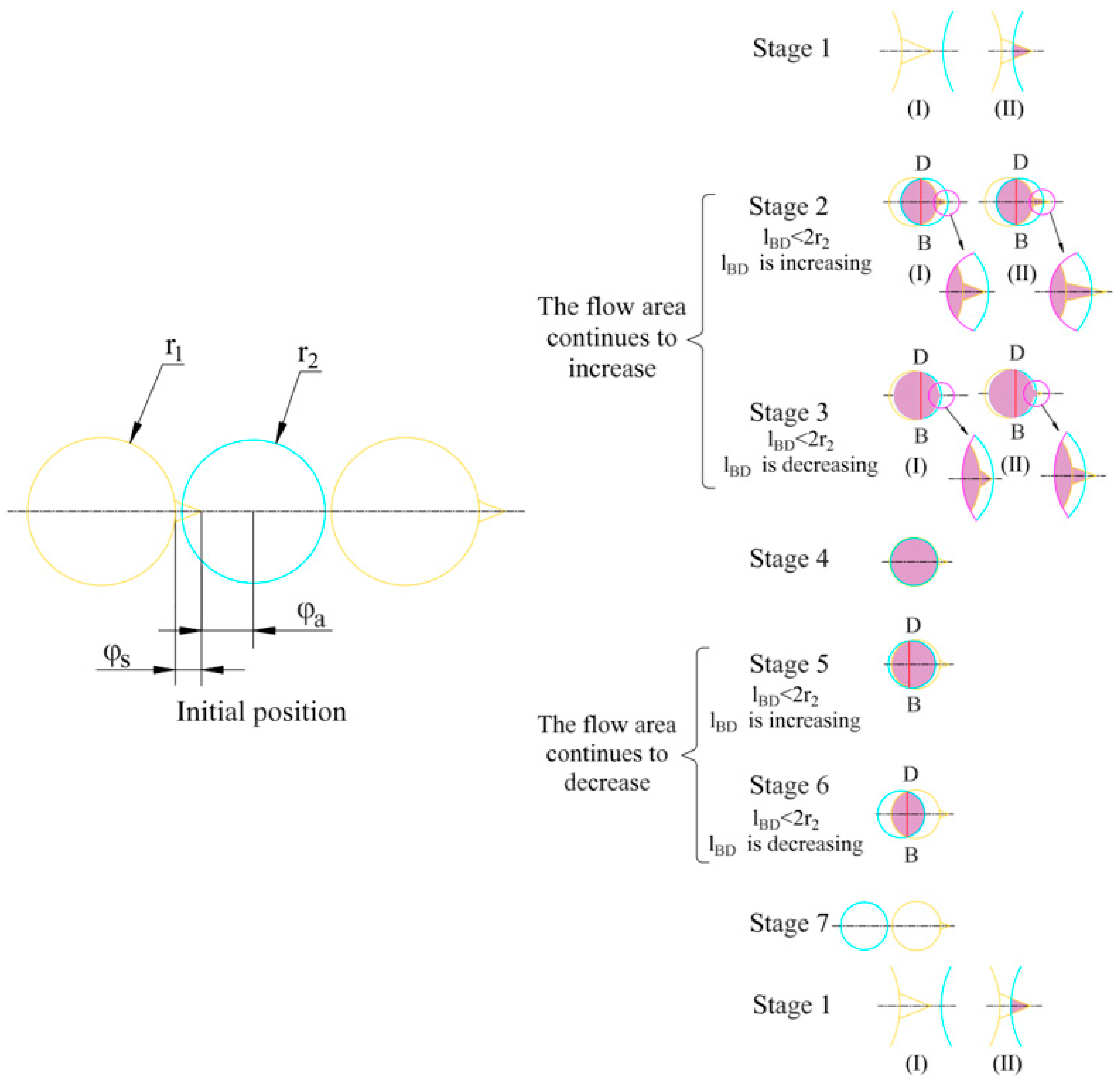
The optimized valve plate is shown in Figure 2b. The plate has 12 holes, and the high-pressure holes and the low-pressure holes are alternately adjacent and evenly distributed. The intermediate point of the two holes is selected as the initial position of the rotor hole, as shown in Figure 3. The flow distribution process can be divided into seven stages according to the relative position of the rotor hole and the valve plate hole, which changes periodically with rotation of the rotor.
The flow distribution process is also shown in Figure 3. Stage 1 is the process in which the rotor hole moves from the initial position to being tangential to the valve plate hole. Due to the different length of the triangular groove, there are two cases in the initial position. The first one is that the length of the triangular groove is small, and the rotor hole is not connected to the triangular groove, as shown in stage 1(I) of Figure 3. The second one is that the length of the triangular groove is large, and the rotor hole is connected to the triangular groove, as shown in stage 1(II) of Figure 3. Stage 2 and stage 3 are the processes of increasing flow area. Stage 2 is the process of the rotor hole moving from the position of the outer tangent to the valve plate hole to the position where the length l BD of common chord of two holes is equal to the diameter of the rotor hole, as shown in stage 2 of Figure 3. The common chord length is directly related to the calculation of the flow area, so it is used as the basis for judging the operation process. According to the length of the triangular groove, this stage can be divided into two cases: the rotor hole is fully connected to the triangular groove, as shown in stage 2(I) of Figure 3; the rotor hole is not completely connected to the triangular groove, as shown in stage 2(II) of Figure 3. Stage 3 is the process of running from the end position of stage 2 to the tangential position between the rotor hole and the valve plate hole, as shown in stage 3 of Figure 3. In the same way as in stage 2, there are two cases in the stage 3. The rotor hole is completely connected to the triangular groove, as shown in stage 3(I) of Figure 3. And another one is shown in stage 3(II) of Figure 3. Stage 4 is the process in which the rotor hole is completely contained in the valve plate hole and the flow area is constant in this stage. Stage 5 and stage 6 are the processes of decreasing flow area. Stage 5 is the process from the tangential position of the rotor hole and the valve plate hole to the position where the common chord length l B D of two holes is equal to the diameter of the rotor hole. Stage 6 is the process of the rotor hole from the end point of stage 5 to the tangential position of the valve plate hole. Stage 7 is the process of moving from the end position of stage 6 to the next initial position. According to the length of the triangular groove, this stage can be divided into two cases: the rotor hole is not connected to the triangular groove, as shown in stage 7(I) of Figure 3; the rotor hole is connected to the triangular groove, as shown in stage 7(II) of Figure 3.

3. Mathematical Model

3.1. Flow Area

The flow area is calculated on the basis of different stages of the flow distribution process. To better express the flow area, the rotation angles at special positions are calculated in advance. Special positions include the rotor hole and the valve plate hole at the outer tangential position, the inner tangential position, and the position where the common chord length l B D is twice as long as r 2 .
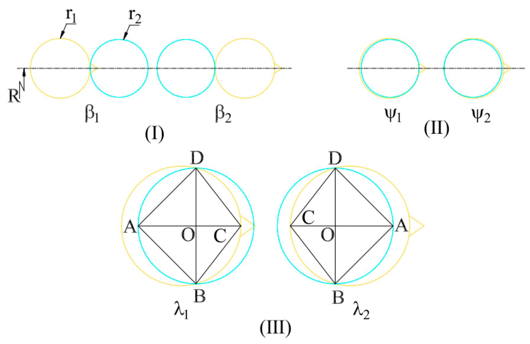
There are two outer tangential positions of the rotor hole and the valve plate hole as shown in Figure 4 (I) during the rotation of the motor, and the rotation angles of these positions are as follows:
β 1 = 15 ° ( 180 · α ) / π
β 2 = 15 ° + ( 180 · α ) / π
where α = 2 · a r c s i n ( r 1 + r 2 / 2 R ) , r 1 is the radius of the valve plate hole, r 2 is the radius of the rotor hole, R is the radius of the distribution circle of the rotor hole, And β 1 and β 2 are rotation angles of the rotor hole and the valve plate hole at the outer tangential position.
Two inner tangential positions between the rotor hole and the valve plate hole are shown in Figure 4 (II) during the rotation of the motor, and the rotation angles of these positions are:
ψ 1 = 15 ° ( 180 · γ ) / π
ψ 2 = 15 ° + ( 180 · γ ) / π
where γ = 2 · a r c s i n ( r 1 r 2 / 2 R ) , and ψ 1 and ψ 2 are rotation angles of the valve plate hole and the rotor hole at the inner tangential position.
During operation, there are two positions where the common chord length between the rotor hole and the valve plate hole is equal to the diameter of the rotor hole, as shown in Figure 4 (III), and the rotation angles at these positions can be solved by the following equation:
r 1 2 4 R 2 s i n 2 15 ° λ 1 2 + r 1 2 r 2 2 4 R s i n ( 15 ° λ 1 2 ) = r 2
λ 2 = 30 ° λ 1
where l B D is the common chord length of the rotor hole and the valve plate hole, and λ 1 and λ 2 are the rotation angles at these positions where l B D is twice as long as r 2 .
When the rotor hole moves in stage 1(I) of Figure 3, 0 ° < φ β 1 and 180 r 2 π R + 180 l π R 15 ° 180 l π R . At this progress, the rotor hole and the valve plate hole cannot be connected, so the flow area is depicted as:
S = 0
where φ is the rotation angle of the rotor, and l is the length of the triangular groove.
When the initial relative position is shown in stage 1(II) of Figure 3, 0 ° < φ β 1 and 180 r 2 π R + 180 l π R > 15 ° 180 l π R . The flow area is the minimum value of the cross-sectional area which is perpendicular to the streamline, as shown in Figure 5. The arc e f ^ is the one that connects the rotor hole and the triangular groove, and it can be approximately considered as a line segment [17]. The flow area can be approximated as:
S = R 2 l + r 1 + r 2 R ( 15 ° φ ) π 180 2 t a n θ 1 s i n θ 1 t a n θ 2 2
where θ 1 is the depth angle of the triangular groove, and θ 2 is the width angle of the triangular groove.
When the rotor hole moves in stage 2 and the relative position is shown in stage 2(I) of Figure 3, β 1 < φ λ 1 and φ 180 r 2 π R 15 ° 180 l π R , and the flow area can be calculated by using the following formula:
S = r 1 2 arcsin l 1 r 1 + r 2 2 arcsin l 1 r 2 l 1 t 1 + S
where l 1 = r 1 2 x 1 2 , x 1 = t 1 2 + r 1 2 r 2 2 2 t 1 , t 1 = 2 R s i n ( 15 ° φ 2 ) , and S = l 2 t a n θ 1 s i n θ 1 t a n θ 2 2 .
When the relative position is shown in stage 2(II) of Figure 3, β 1 < φ λ 1 and φ 180 r 2 π R > 15 ° 180 l π R , and the flow area can be calculated by using the following formula:
S = r 1 2 arcsin l 1 r 1 + r 2 2 arcsin l 1 r 2 l 1 t 1 + S R 2 φ 15 ° π 180 + l r 2 R 2 t a n θ 1 s i n θ 1 t a n θ 2 2
When the rotor hole moves in stage 3 and the relative position is shown in stage 3(I) of Figure 3, λ 1 < φ ψ 1 and φ 180 r 2 π R 15 ° 180 l π R , and the flow area can be calculated by using the following formula:
S = r 1 2 arcsin l 1 r 1 + r 2 2 arcsin l 1 r 2 + π r 2 2 l 1 t 1 + S
When the relative position is shown in stage 3(II) of Figure 3, λ 1 < φ ψ 1 and φ 180 r 2 π R > 15 ° 180 l π R , and the flow area can be calculated by using the following formula:
S = r 1 2 arcsin l 1 r 1 r 2 2 arcsin l 1 r 2 + π r 2 2 l 1 t 1 + S R 2 φ 15 ° π 180 + l r 2 R 2 t a n θ 1 s i n θ 1 t a n θ 2 2
When the rotor hole moves in stage 4, the position is shown in stage 4 of Figure 3. At this time, the rotor hole coincides with the valve plate hole ( ψ 1 < φ ψ 2 ), and the flow area can be calculated by using the following formula:
S = π r 2 2
When the rotor hole moves in stage 5, ψ 2 < φ λ 2 , as shown in stage 5 of Figure 3, and the flow area can be calculated by using the following formula:
S = r 1 2 arcsin l 2 r 1 + r 2 2 arcsin l 2 r 2 + π r 2 2 l 2 t 2
where l 2 = r 1 2 x 2 2 , x 2 = t 2 2 + r 1 2 r 2 2 2 t 2 , and t 2 = 2 R s i n ( φ 15 ° 2 ) .
When the rotor hole moves in stage 6, as shown in stage 6 of Figure 3, λ 2 < φ β 2 , and the flow area can be calculated by using the following formula:
S = r 1 2 arcsin l 2 r 1 + r 2 2 arcsin l 2 r 2 l 2 t 2
When the rotor hole moves in stage 7 and the position is shown in stage 7(I) of Figure 3, β 2 < φ 60 ° and 180 r 2 π R + 180 l π R 15 ° 180 l π R , and the flow area can be calculated by using the following formula:
S = 0
When the position is stage 7(II) of Figure 3, β 2 < φ 60 ° and 180 r 2 π R + 180 l π R > 15 ° 180 l π R , and the flow area can be calculated using the following formula:
S = R 2 l + r 1 + r 2 R ( 75 ° φ ) π 180 2 t a n θ 1 s i n θ 1 t a n θ 2 2
When continuing to rotate, the rotor hole returns to stage 1.

3.2. Torque Pulsation Rate

During the working process of cam ring motors, the rotor hole and the valve plate hole are alternately connected, and the pressure in the piston chamber changes periodically. The pressure pulsation is related to the inlet and outlet flow rate, the volume change in the piston chamber, and the oil characteristics. According to the conservation of mass, the relationship between the mass flow into and out of the piston chamber and the mass flow leakage from the piston chamber are as follows:
d d t V ρ = Q m ( i n ) + Q m ( o u t ) + Q m ( l e a k )
d d t V ρ = V d ρ d t + ρ d V d t
where V is the volume of the piston chamber, ρ is the hydraulic oil density, Q m ( i n ) is the mass flow rate flowing into the piston chamber, Q m ( o u t ) is the mass flow rate flowing out of the piston chamber, and Q m ( l e a k ) is the mass flow rate leakage from the piston chamber.
The variation in the density with time can be expressed as:
d ρ d t = ρ K d p d t
where p is the piston chamber pressure, K is the hydraulic oil bulk modulus, and K = d p V d V .
Take Equation (20) into Equation (19):
d d t V ρ = ρ ( V K d p d t + d V d t )
As shown in Figure 6, assuming the hydraulic oil density remains constant, the piston chamber pressure can be obtained as:
d p d t = K V ( Q m ( i n ) Q m ( o u t ) Q m ( l e a k ) + d V d t )
The volume of the piston chamber can be expressed as:
V = V 0 + s A p
The volume change with time can be expressed as:
d V d t = ν A p
Substitute Equations (23) and (24) into Equation (22):
d p d t = K V 0 + s A p ( Q i n Q o u t Q l e a k + ν A p )
where Q i n is the volume flow rate into the piston chamber, Q o u t is the volume flow rate flowing out of the piston chamber, Q l e a k is the volume flow rate of the piston chamber leakage, V 0 is the initial volume of the piston chamber, s is the piston displacement, ν is the piston velocity, and A p is the cross-sectional area of the piston.
The flowing into the piston chamber is:
Q i n = C · S 2 p h p p ρ s i g n p h p p                                           ( k π 3 , π 6 + k π 3 ) 0                                                                                                                         ( π 6 + k π 3 , π 3 + k π 3 )
where C is the flow coefficient, and p h p is the inlet pressure of the motor.
The flow rate flowing out of the piston chamber is:
Q o u t = C · S 2 p p l p ρ s i g n p p l p                               ( π 6 + k π 3 , π 3 + k π 3 ) 0                                                                                                                                             ( k π 3 , π 6 + k π 3 )
where p l p is the outlet pressure of the motor.
During the rotation of the motor, the leakages mainly include the piston pair leakage and the flow distribution pair leakage [18]. The piston pair leakage consists of differential pressure flow and shear flow. The leakage amount is:
Q 1 = π d z δ 3 12 μ l s 1 + 1.5 ε 2 p π d z δ ν r 2
where d z is the piston diameter, δ is the gap between the piston and the piston hole, μ is oil dynamic viscosity, l s is the contact length of the piston pair, ε is the eccentricity between the piston and the piston bore, p is the pressure difference between the high-pressure piston chamber and the case, and ν r is the linear velocity of the piston relative to the rotor.
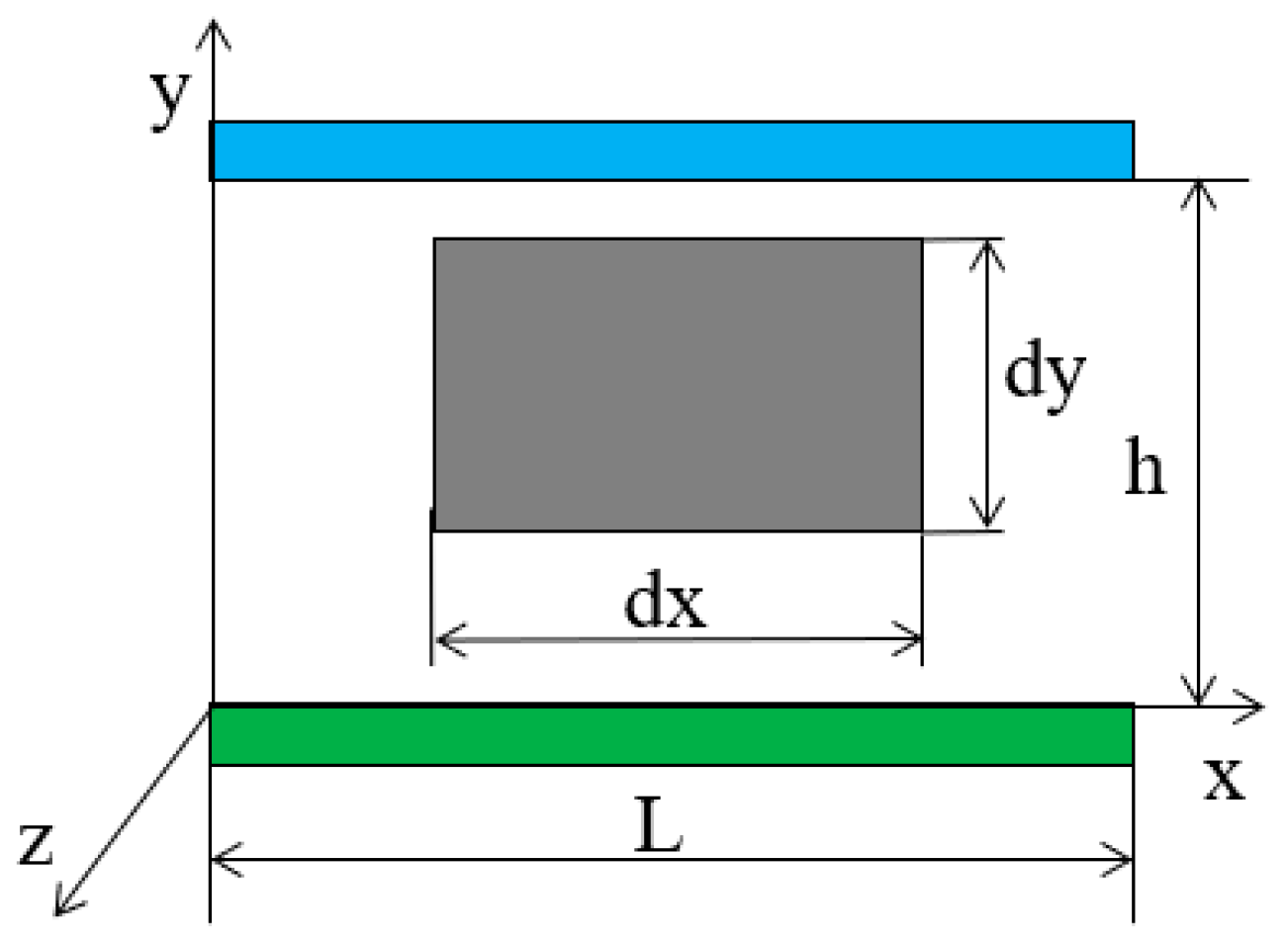
The rotor and the valve plate form a friction pair in the relative motion. During the rotation of the rotor, high-pressure oil enters the gap of the pair and causes the leakage between the rotor and the valve plate. The leakage flow rate can be simplified as the gap flow rate between two parallel plates with relative motion shown in Figure 7. The leakage flow rate can be calculated by using:
Q = A u d A = 0 h p 2 μ L h y y 2 + U h y d y = p b h 3 12 μ L + U B h 2
where u = p 2 μ L h y y 2 + U h y , Q is the flow rate between the rotor and the valve plate, B is the gap width between parallel plates, h is the clearance height between the rotor and the valve plate, L is the gap length between the rotor and the valve plate, y is the ordinate of the particle, and u is the flow velocity of the particle at the y-axis.
The leakage between the rotor and the valve plate flows in a radial direction, and the relative radial motion velocity between the rotor and the valve plate is 0. Based on the finite element analysis, the leakage amount at each node of the rotor and the valve plate is:
Q i , j = ( P i , j P i 1 . j ) B h 3 12 μ r i , j φ
where Q i , j is the leakage between the rotor and the valve plate at a particle, P i , j , P i 1 . j is the pressure at a particle, r i , j is the radius of the gap length, and φ is the angle of the gap length.
The leakage between the port of rotor and the valve port is:
Q 2 = i j ( P i , j P i 1 . j ) B h 3 12 μ r i , j φ
where Q 2 is the leakage between the rotor and the valve plate.
The leakage amount of the piston chamber is:
Q l e a k = Q 1 + Q 2
The instantaneous torque of the motor is:
M s h = π d z 2 4 P i ν ϕ i
where M s h is the instantaneous torque of the motor, and ν ϕ i is the degree velocity of the piston.
Motor torque pulsation rate is:
δ T = max M s h min M s h mean M s h
Under the premise of ignoring the power loss, the motor torque pulsation rate can be expressed as:
δ T = max ν ϕ i min ν ϕ i mean ν ϕ i
where ν ϕ i is the sum of the degree velocity of each piston in the high-pressure working area at a certain time.
From the above analysis, it can see that the flow area change rate and the volume change rate of the piston chamber determine the piston chamber pressure. And the pressure acts on the piston to form the output torque. Therefore, optimizing the design parameters of the triangular groove can improve the stability of the motor.

4. Model Construction and Verification

4.1. Model Construction

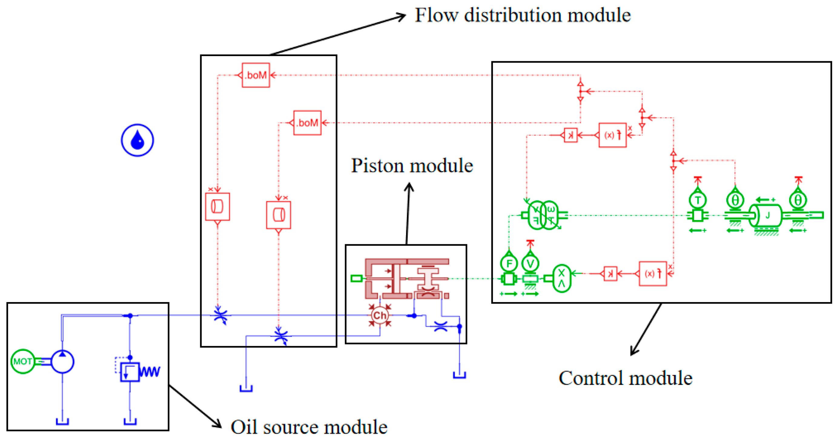
The numerical simulation model of the cam ring motor is built using the AMEsim simulation system. The numerical simulation model of the motor is shown in Figure 8, which is mainly composed of an oil source module, a flow distribution module, a piston module, and a control module.
During operation, the force on the piston is converted into torque output and drives the load to rotate. The control module can convert the rotation angle of the rotor into specific signal feedback to control the opening area of the rotor hole and the valve plate hole. And the flow distribution module simulates the flow area changes between the rotor hole and the valve plate hole by adjusting the flow area of the throttle hole. The piston module is composed of sub models in the HCD library, which can simulate the axial movement of the piston and the leakage during the process. A throttle valve is used to simulate the leakage between the valve plate and the rotor. The single piston model is shown in Figure 9. The oil source module provides high-pressure oil for the system, mainly composed of a motor, pump, and safety valve. Referring to the actual piston arrangement of the motor, the entire motor simulation model can be completed.
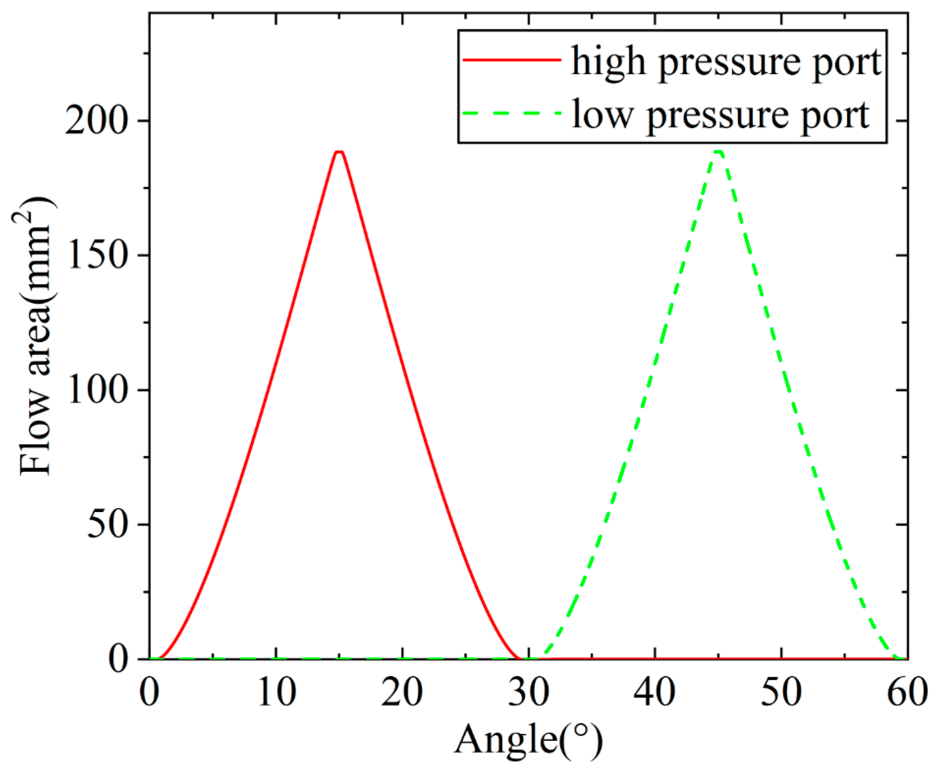
The flow area varies with the change in the depth angle, the width angle, the length of the triangular groove, and the rotation angle of motor. The curve of flow area changing with the rotation angle is shown in Figure 10: when the width angle is 90°, the depth angle is 15°, and the length is 1.6 mm. The parameters of its components are shown in Table 1.

4.2. Simulation Result

The displacement and velocity curves of a single piston are shown in Figure 11 and the pressure and flow curves of a single piston chamber are shown in Figure 12 with the rotating speed of 1 r/min and under the inlet pressure of 100 bar. Since the motor is a six acting cam ring motor with double rows and eight pistons, when it rotates one circle, the piston acts six times. The piston working cycle is 60°. Therefore, the region from 60° to 120° is selected for analysis. As shown in the figure, during the region from 60° to 90°, the rotor hole connects to the high-pressure hole of the valve plate, and the piston moves outward along the stator guide rail. When the region is 90° to 120°, the rotor hole connects to the low-pressure hole of the valve plate, and the piston moves back along the stator guide rail. It conforms to the actual motion law of the cam ring motor.
There are fluctuations in the simulation results because of a closed dead zone on the valve plate. When the rotor hole is in the closed dead zone, there is a phenomenon of trapped oil, which changes the piston chamber pressure, resulting in fluctuations of the piston velocity and the piston chamber flow. In addition, when the piston is not in the closed dead zone, the piston chamber pressure is affected by the other chamber pressure, the piston of which is in the dead zone, causing fluctuations in the speed, the torque, and the flow.
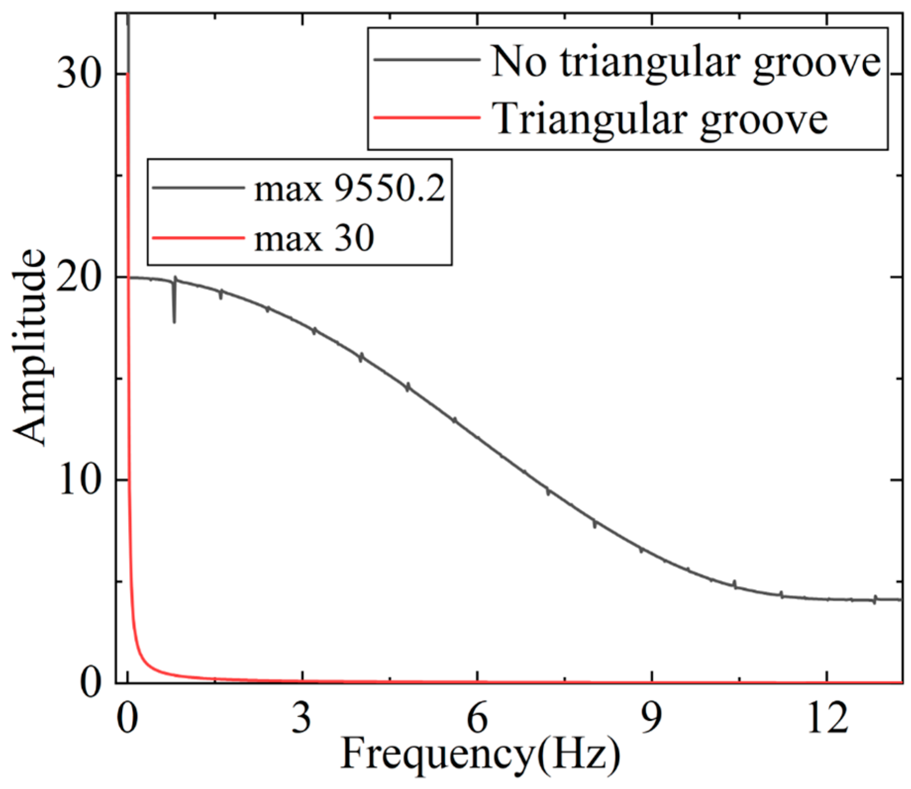
In order to study the frequency characteristics of torque pulsation, a spectrum analysis on the simulation results has been made and the results are shown in Figure 13. The maximum amplitude is 9550.2 when there is no triangular groove, and 30 when there are triangular grooves processed on the valve plate. It shows that the motor stability is obviously improved after the installation of the valve plate with triangular grooves.

4.3. Experimental Verification

In order to verify the correctness of the numerical simulation model, a motor pressure pulsation test bench was established, and the experimental data were collected and compared with the simulation data. The test bench and its hydraulic schematic diagram are shown in Figure 14 and Figure 15. The test bench uses a torque motor as the load. The directional control valve is used to change the direction of the motor rotation, the electromagnetic relief valve is used to adjust the system pressure, and the proportional speed control valve is used to control the flow rate of the test motor. The bridge hydraulic block ensures that oil can be supplied to the low-pressure side regardless of the direction of motor rotation. The pressure sensor from Nanjing Hong Mu collects the inlet pressure of the motor, and the model is HM90G-H3-2-V2-F1-W2, the accuracy is ±0.25%FS, and the sampling frequency is 200 kHz. The motor speed in the experiment is 10 r/min.
The comparison between the simulation results and the experimental data is shown in Figure 16. The main reason why the experimental data fluctuate greatly is the vibration of the test bench; the unstable inlet pressure and the electromagnetic field generated by the motor during operation interferes with the signal data line. However, the simulation results were carried out under ideal conditions, so the simulation results are relatively stable. But the trend of the simulation results is perfectly consistent with the experimental results. Therefore, this mathematical model can effectively reflect the output characters, proving the correctness of the simulation model and mathematical mechanism.

5. The Influence of The Triangular Groove Structure Parameters

5.1. The Influence of The Triangular Groove Depth Angle

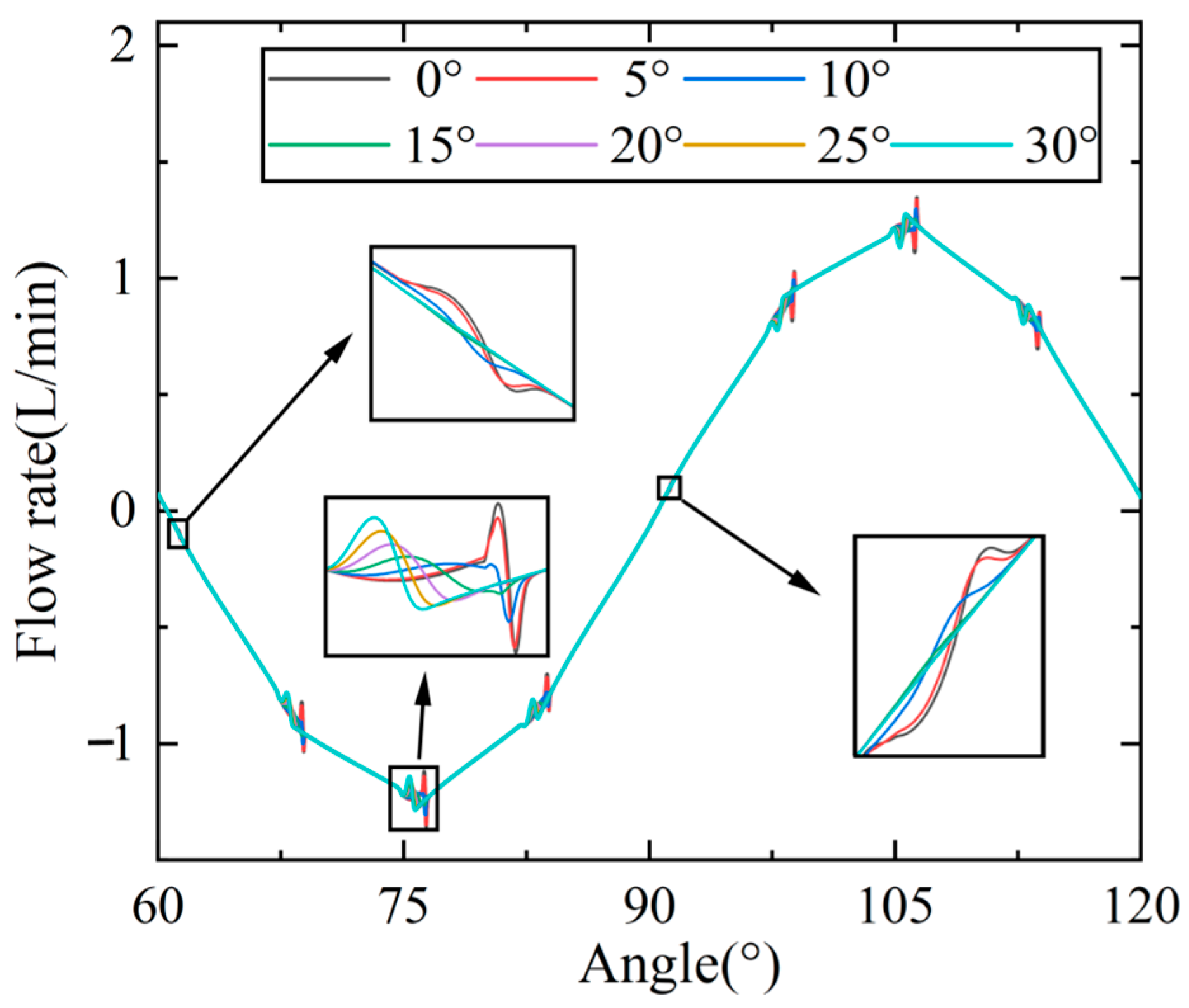
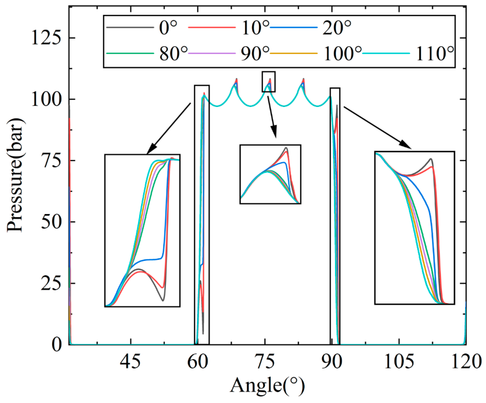
The depth of the triangular groove is mainly determined by the depth angle θ 1 . As the depth angle increases, the flow area enlarges correspondingly, and the flow capacity increases too. To analyze the influence of the depth angle of the triangular groove on the pressure and the flow rate, the numerical simulation model is run under the same working conditions with only changing the depth angle. The effect of different depth angles of the triangular groove on flow rate in the piston chamber is shown in Figure 17. The effect of different depth angles of the triangular groove on pressure in the piston chamber is shown in Figure 18.
The simulation results show that, when θ 1 is less than 10 ° , as the depth angle of the triangular groove diminishes, the flow area of the triangular groove decreases, and the damping effect increases. When the rotor hole moves to the transition zone, due to poor flow capacity between the rotor hole and the valve plate hole, the input flow Q i n of the piston chamber decreases, and the phenomena of trapped oil become more and more frequent. The change in the piston chamber volume is the dominant factor for pressure changes, leading to the piston chamber pressure rising first and then decreasing, such as in the case of depth angles of 0° and 5°, so that the flow and the pressure fluctuations increase in the piston chamber, resulting in an increase in the motor torque pulsation rate, as shown in Figure 19. When θ 1 is greater than 20 ° , as the depth angle increases, the flow area increases. When the rotor hole moves to the transition zone, the oil trapping significantly weakens. However, due to the improper matching between the change rate of flow area with the piston speed, the smoothness of the output torque decreases, while the torque pulsation rate increases, as shown in Figure 19.

5.2. The Influence of The Triangular Groove Width Angle

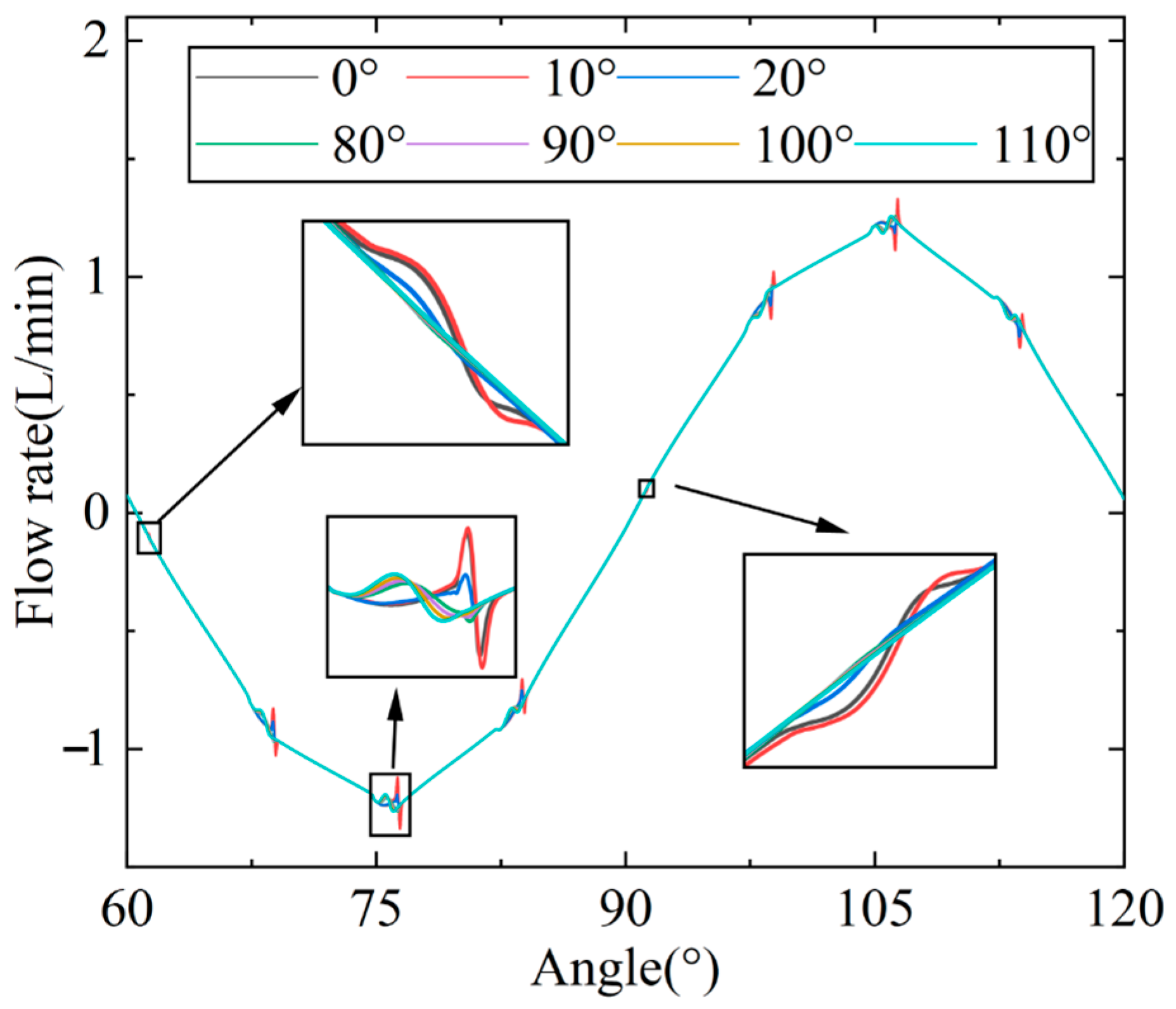
The width of the triangular groove is mainly determined by the width angle θ 2 . As the width angle increases, the flow area enlarges accordingly, and the flow capacity increases. To analyze the influence of the width angle of the triangular groove on the pressure and the flow rate, the numerical simulation model is run under the same working conditions with only changing the width angle. The effect of different width angles of the triangular groove on flow rate in the piston chamber is shown in Figure 20. The effect of different width angles of the triangular groove on pressure in the piston chamber is shown in Figure 21.
The simulation results show that, when θ 2 is less than 20 ° , as the width angle of the triangular groove decreases, the flow area of the triangular groove decreases, and the damping effect increases. Like the change in the depth angle of the triangular groove, the flow and pressure fluctuations in the piston chamber intensify due to poor oil flow capacity between the rotor hole and the valve plate hole. When θ 2 is greater than 100 ° , as the depth angle increases, the flow area increases, so the oil trapping in the transition zone of the piston chamber significantly decreases. However, due to the mismatch between the change rate of the flow area and the piston speed, the smoothness of the output torque decreases, so the torque pulsation rate increases, as shown in Figure 22.

5.3. Influence of Length of The Triangular Groove

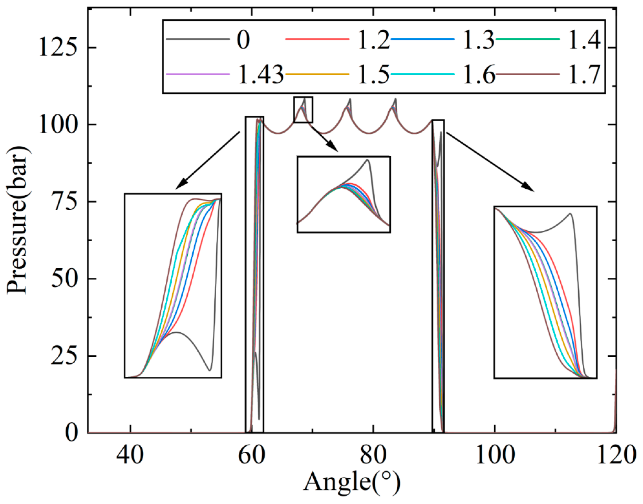
The longer the triangular groove is, the earlier it contacts with the rotor hole. When the rotor moves to the same position, the longer the triangular groove is, the stronger the flow capacity is. To analyze the influence of the length of the triangular groove on the pressure and the flow rate, the numerical simulation model is run under the same working conditions with only changing the length. The effect of different lengths of the triangular groove on the flow rate in the piston chamber is shown in Figure 23. The effect of different lengths of the triangular groove on pressure in the piston chamber is shown in Figure 24.
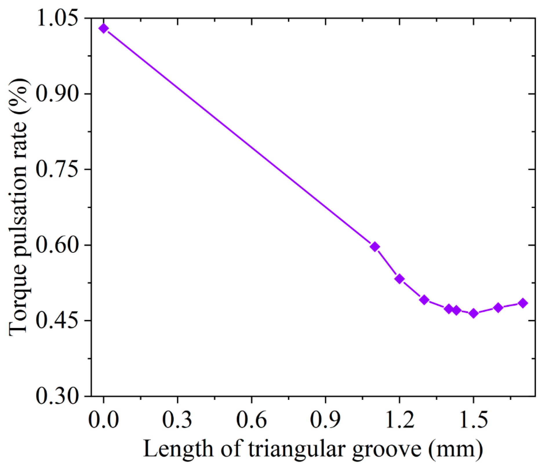
The simulation results show that, when the length of the triangular groove l is less than 1.3 mm, as the length of the triangular groove decreases, when the rotor moves to the same position, the smaller the flow area of the triangular groove is, the greater the damping effect is. When the rotor hole moves to the transition zone, due to the poor flow capacity between the rotor hole and the valve plate hole, the oil trapping is obvious. Similarly to the previous process, the pressure in the piston chamber first increases and then decreases, leading to an increase in flow and pressure fluctuations in the piston chamber, as well as an increase in the torque pulsation rate. When the length of the triangular groove l is greater than 1.43 mm, the rotor hole has already communicated with the next valve plate hole before it has separated from the previous valve plate hole. This phenomenon, within a certain range, will improve motor torque stability. When the length of the triangular groove l is greater than 1.6 mm, as the length increases, the oil trapping in the transition zone of the piston chamber decreases. However, due to the improper matching between the change rate of the flow area and the piston speed, the smoothness of the output torque decreases, so the torque pulsation rate increases. The variation diagram of torque pulsation rate is shown in Figure 25. The length of the triangular groove should be optimized to obtain a suitable value; otherwise, there will be a decrease in volumetric efficiency.

6. Response Surface Analysis of The Triangular Groove Design Parameters

According to the above analysis results, the response surface test analysis of the motor torque pulsation rate was carried out by using the Box–Behnken method, and the quadratic polynomial regression equation is obtained as follows:
Y = 0.0653 θ 1 2 + 0.0066 θ 2 2 + 0.01 l 2 + 0.021 θ 1 θ 2 + 0.0442 θ 1 l + 0.0001 θ 2 l + 0.0297 θ 1 + 0.0077 θ 2 + 0.0171 l + 0.4558
The results of the variance regression model analysis are shown in Table 2 [19,20,21,22,23].
Table 3 shows that the lack of fit is not significant when the P of the model is less than 0.0001, indicating that the equation is significant. The fitting degree of 99.85% means the fitting degree is good. The correlation coefficient R a d j 2 equals 0.9967, and the model can explain about 99% of the change in response values. The discrete coefficient is C V equals 0.5751%, which is less than 10%. The motor torque pulsation rate can be analyzed and predicted via the equation instead of simulation calculations.
From the p-value, θ 2 l has no significant effect on the motor torque pulsation rate (P is greater than 0.05), while others are significant (P is less than 0.05). According to the F-value, the influence order of the three factors of the triangular groove on the torque pulsation rate is θ 1 > l > θ 2 . The coupling between the depth angle and the length has the most significant effect on the motor torque pulsation rate, followed by the width angle and the depth, and finally the width angle and the length.
Through response surface analysis, the optimal results were obtained, with a depth angle of 15.529°, a width angle of 91.828°, a length of 1.515 mm. Comparing the response surface analysis results with the simulation results, as shown in Table 3, the error is 3%. The results can verify the effectiveness of the optimization method. And comparing the simulation results without the triangular groove with those after optimizing grooves, it shows that by adding the triangular groove with the valve plate, the torque pulsation rate of the motor is reduced by 55%.

7. Conclusions

In this paper, the influence of the design parameters of the triangular groove on the torque pulsation rate of the motor is analyzed, and the optimal design parameters of the triangular groove are obtained by the response surface method.
  • Adjusting the triangular groove parameters can effectively reduce the torque pulsation rate of the motor and improve its stability at low speed. Through the response surface analysis, the optimal design parameters of the triangular groove were obtained: depth angle 15.529°, width angle 91.828°, length 1.515 mm. The valve plate with these parameters can reduce the motor torque ripple rate by 55%.
  • Through the response surface analysis, it can see from the F-value that the order of influence of the three factors on the motor torque pulsation rate is θ 1 > l > θ 2 ; the coupling effect between the depth angle and length of the triangular groove is more obvious to reduce the torque pulsation rate than other parameter combinations.

Author Contributions

Conceptualization, W.W., G.A. and H.D.; methodology, W.W., G.A. and H.D.; software, W.W.; validation, W.W., B.L., and H.D.; formal analysis, W.W.; investigation, W.W., W.S., Z.H. and B.L.; resources, W.W., G.A. and H.D.; data curation, W.S. and Z.H.; writing—original draft preparation, W.W.; writing—review and editing, W.W. and B.L. All authors have read and agreed to the published version of the manuscript.

Funding

This research has been supported by the National Key R&D Program of China (Grant No.2021YFB3400502).

Data Availability Statement

No applicable.

Conflicts of Interest

The authors declare no conflict of interest.

References

  1. Mandal, S.K.; Dasgupta, K. Theoretical and experimental studies on the steady-state performance of low-speed high-torque hydrostatic drives. Part 2: Experimental investigation. Proc. Inst. Mech. Eng. Part C J. Mech. Eng. Sci. 2009, 223, 2675–2685. [Google Scholar] [CrossRef]
  2. Nilsson, D.; Prakash, B. Investigation into the seizure of hydraulic motors. Tribol. Int. 2010, 43, 92–99. [Google Scholar] [CrossRef]
  3. Dasgupta, K.; Mandal, S.K.; Pan, S. Dynamic analysis of a low speed high torque hydrostatic drive using steady-state characteristics. Mech. Mach. Theory 2012, 52, 1–17. [Google Scholar] [CrossRef]
  4. Chen, R.; Shrive, C.; Wan, Y.; Chen, X.; Shao, Y. Brake piston design for a new radial plunger motor. J. Phys. Conf. Ser. 2022, 2228, 12–28. [Google Scholar] [CrossRef]
  5. Kim, J.K.; Kim, H.E.; Jung, J.Y.; Oh, S.H.; Jung, S.H. Relation between pressure variations and noise in axial type oil piston pumps. KSME Int. J. 2004, 18, 1019–1025. [Google Scholar] [CrossRef]
  6. Ye, S.G.; Zhang, J.H.; Xu, B. Noise reduction of an axial piston pump by valve plate optimization. Chin. J. Mech. Eng. 2018, 31, 57. [Google Scholar] [CrossRef]
  7. Xu, B.; Sun, Y.H.; Zhang, J.H.; Sun, T.; Mao, Z.B. A new design method for the transition region of the valve plate for an axial piston pump. J. Zhejiang Univ. 2015, 3, 229–240. [Google Scholar] [CrossRef]
  8. Wang, D.Y.; Chen, C.C.; Dong, H.K. Investigation of the Pressure Fluctuation of Plunger chambers with Variable Slot Geometry. Machines 2023, 11, 225. [Google Scholar] [CrossRef]
  9. Sjödin, U.I.; Olofsson, U.L.O. Initial sliding wear on piston rings in a radial piston hydraulic motor. Wear 2003, 254, 1208–1215. [Google Scholar] [CrossRef]
  10. Pettersson, U.; Jacobson, S. Textured surfaces for improved lubrication at high pressure and low sliding speed of roller/piston in hydraulic motors. Tribol. Int. 2007, 40, 355–359. [Google Scholar] [CrossRef]
  11. Zhang, X.L.; Zhang, J.H.; Xu, B.; Yang, Z.Q.; Zhao, Q.; Zhang, H.J. The effect of slotted hole on minimum oil film thickness of piston in radial piston hydraulic motor. In Proceedings of the ASME/BATH 2021 Symposium on Fluid Power and Motion Control, Online, 19 October 2021. [Google Scholar]
  12. Zhang, X.L.; Zhang, J.H.; Zhang, H.J.; Xu, B. Optimized design of cam ring curve of cam lobe radial-piston motor. J. Huazhong Univ. Sci. Technol. 2021, 49, 30–35. [Google Scholar]
  13. Zhang, C.; Tan, H.; Fang, Y.; Zhang, X.; Yang, Y.; Duan, Y.; Zhang, J. Deformation pre-compensated optimization design of cam ring for low pulsation hydraulic motors. J. Zhejiang Univ. 2023, 24, 130–145. [Google Scholar] [CrossRef]
  14. Kosodo, H.; Nara, M.; Kakehida, S.; Imanari, Y. Experimental research about pressure-flow characteristics of V-notch. Proc. JFPS Int. Symp. Fluid Power 1996, 1996, 73–78. [Google Scholar] [CrossRef]
  15. Mo, T.; Deng, B.; Ke, J.; Liu, H.L.; Wang, G.Z. Simulation Analysis of Valve Plate of Axial Piston Water Motor Based on CFD. Mach. Tool Hydraul. 2015, 43, 182–184, 216. [Google Scholar]
  16. Ni, J.; Feng, G.D.; Wang, Z.Q.; Gao, D.R. Optimized design of hydraulic motor with inner curve end face distribution. J. Zhejiang Univ. 2017, 51, 946–953. [Google Scholar]
  17. Na, C.L. Calculation of orifice area of triangle groove. J. Gansu Polytech. Univ. 1993, 19, 45–48. [Google Scholar]
  18. Wang, Z.Q.; Xiang, J.B.; Fu, Q.; Wood, R.J.; Wang, S.C. Study on the friction performance of textured surface on water hydraulic motor piston pair. Tribol. Trans. 2022, 65, 308–320. [Google Scholar] [CrossRef]
  19. Jin, Y.; Liu, S.J. Response surface method-based fatigue reliability analysis of rolling bearing considering thermoelastic-hydrodynamic lubrication effect. J. South China Univ. Technol. 2017, 45, 84–90. [Google Scholar]
  20. Hou, S.P.; Yu, H.Y.; Gong, H.X.; Xu, H.S. Cushioning performance optimization of carrying and docking device for manned carrier. J. Huazhong Univ. Sci. Technol. 2020, 48, 109–114. [Google Scholar]
  21. Colombo, F.; Della Santa, F.; Pieraccini, S. Multi-objective optimisation of an aerostatic pad: Design of position, number and diameter of the supply holes. J. Mech. 2020, 36, 347–360. [Google Scholar] [CrossRef]
  22. Dai, W.; He, L.; Pan, Y.; Zhang, S.P.; Hou, L. Improved Vehicle Vibration Control through Optimization of Suspension Parameters Using the Response Surface Method and a Non-Linear Programming with a Quadratic Lagrangian Algorithm. Actuators 2023, 12, 297–314. [Google Scholar] [CrossRef]
  23. Ren, J.; Zhou, F.; Wang, N.; Hu, G. Multi-objective optimization design and dynamic performance analysis of an enhanced radial magnetorheological valve with both annular and radial flow paths. Actuators 2022, 11, 120–144. [Google Scholar] [CrossRef]
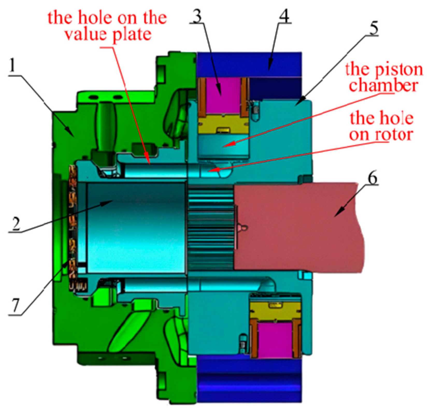
Figure 1. Structural schematic diagram of the cam ring motor. 1. Outer case; 2. valve plate; 3. piston assembly; 4. stator; 5. rotor; 6. output shaft; 7. spring.
Actuators 12 00388 g001
Figure 2. The valve plate structure diagram. (a) The valve plate of the cam ring motor. (b) The optimized valve plate.
Actuators 12 00388 g002
Figure 3. Seven stages of the connection between the rotor hole and the valve plate hole.
Actuators 12 00388 g003
Figure 4. The flow area between the rotor hole and the valve plate hole. (I) Rotation angles of the rotor hole and the valve plate hole in the outer tangential position. (II) Rotation angles of the rotor hole and the valve plate hole in the inner tangential position. (III) The common chord length between the rotor hole and the valve plate hole is equal to twice the radius of the rotor hole.
Actuators 12 00388 g004
Figure 5. The structure diagram of the triangular groove.
Actuators 12 00388 g005
Figure 6. Flow diagram.
Actuators 12 00388 g006
Figure 7. Schematic diagram of parallel plane slot flow. Green is the valve plate. Blue is the rotor. Gray is the hydraulic oil.
Actuators 12 00388 g007
Figure 8. Numerical simulation model of the cam ring motor.
Actuators 12 00388 g008
Figure 9. The single piston model of the cam ring motor.
Actuators 12 00388 g009
Figure 10. Flow area change curve.
Actuators 12 00388 g010
Figure 11. The single piston displacement and velocity curve.
Actuators 12 00388 g011
Figure 12. The single piston pressure and flow curve.
Actuators 12 00388 g012
Figure 13. Motor torque fluctuation frequency diagram with or without triangular groove.
Actuators 12 00388 g013
Figure 14. Picture of the experimental bench. (a) Test stand front side. (b) Test stand back side.
Actuators 12 00388 g014
Figure 15. Schematic diagram of the experimental bench.
Actuators 12 00388 g015
Figure 16. Comparison of pressure pulsation simulation results with experimental data.
Actuators 12 00388 g016
Figure 17. Effect of different depth angles of the triangular groove on flow rate in the piston chamber.
Actuators 12 00388 g017
Figure 18. Effect of different depth angles of the triangular groove on pressure in the piston chamber.
Actuators 12 00388 g018
Figure 19. Torque pulsation rate corresponding to different depth angles of the triangular groove.
Actuators 12 00388 g019
Figure 20. Effect of different width angles of the triangular groove on flow rate in the piston chamber.
Actuators 12 00388 g020
Figure 21. Effect of different width angles of the triangular groove on pressure in the piston chamber.
Actuators 12 00388 g021
Figure 22. Torque pulsation rate corresponding to different width angles of the triangular groove.
Actuators 12 00388 g022
Figure 23. Effect of different lengths of the triangular groove on the flow rate in the piston chamber.
Actuators 12 00388 g023
Figure 24. Effect of different lengths of the triangular groove on pressure in the piston chamber.
Actuators 12 00388 g024
Figure 25. Torque pulsation rates corresponding to different lengths of the triangular groove.
Actuators 12 00388 g025
Table 1. Simulation model parameter setting.
Parameter NameParameter Value
piston diameter/mm58
gap between piston and piston chamber/mm0.01
valve plate gap/mm0.01
outlet volume/mm3(first row) 29.987
(second row) 38.73
motor speed/r/min1
motor displacement/L/r6.08
Table 2. Regression model analysis of variance.
SourceSum of SquaresdfMean SquareF-Valuep-ValueSignificance or Non-Significance
Model0.038790.0043531.89<0.0001Significance
A-Depth angle0.007110.0071873.15<0.0001Significance
B-Width angle0.000510.000558.650.0001Significance
C-Length0.002310.0023290.53<0.0001Significance
AB0.001810.0018217.97<0.0001Significance
AC0.007810.0078967.18<0.0001Significance
BC1.051 × 10−811.051 × 10−80.00130.9722Non-significance
0.01810.0182224.3<0.0001Significance
0.000210.000222.490.0021Significance
0.000410.000452.260.0002Significance
Residual0.000178.082 × 10−6
Lack of Fit0.000030.00003.430.1325Non-significance
Pure Error0.000043.961 × 10−6
Cor Total0.038716
R20.9985
R2adj0.9967
R2pred0.9825
Adeq Precision80.0716
CV0.5751%
Table 3. Torque pulsation rate with or without the triangular groove.
No The Triangular GrooveThe Triangular Groove
Response Surface AnalysisModel Verification
Torque pulsation rate1.03%0.446%0.46%
Disclaimer/Publisher’s Note: The statements, opinions and data contained in all publications are solely those of the individual author(s) and contributor(s) and not of MDPI and/or the editor(s). MDPI and/or the editor(s) disclaim responsibility for any injury to people or property resulting from any ideas, methods, instructions or products referred to in the content.