Abstract
Since robotic arms operating close to people are becoming increasingly common, there is a need to better understand how they can be made safe when unintended contact occurs, while still providing the required performance. Several actuators and methods for improving robot safety are studied and compared in this paper. A robotic arm moving its end effector horizontally and colliding with a person’s head is simulated. The use of a conventional electric actuator (CEA), series elastic actuator (SEA), pneumatic actuator (PA) and hybrid pneumatic electric actuator (HPEA) with model-based controllers are studied. The addition of a compliant covering to the arm and the use of collision detection and reaction strategies are also studied. The simulations include sensor noise and modeling error to improve their realism. A systematic method for tuning the controllers fairly is proposed. The motion control performance and safety of the robot are quantified using root mean square error (RMSE) between the desired and actual joint angle trajectories and maximum impact force (MIF), respectively. The results show that the RMSE values are similar when the CEA, SEA, and HPEA drive the robot’s first joint. Regarding safety, using the PA or HPEA with a compliant covering can reduce the MIF below the safety limit established by the International Organization for Standardization (ISO). To satisfy this ISO safety limit with the CEA and SEA, a collision detection and reaction strategy must be used in addition to the compliant covering. The influences of the compliant covering’s stiffness and the detection delay are also studied.
1. Introduction
Robotic arms operating close to people are becoming increasingly common. Industrial applications of these robots include assisting workers with assembly tasks, while non-industrial applications include “assistive robots” for improving the quality of life of older adults and people with disabilities. These applications require robots that combine safety with performance in terms of their motion control. However, the conventional actuators used to drive the joints of robotic arms—namely, electric motors coupled with harmonic drive transmissions (HDT)—emphasize motion control performance over safety. The conventional electric actuator (CEA) and its control system are designed for high stiffness. In addition, the reflected inertia of the motor at the output of a CEA is amplified by the square of the HDT’s reduction ratio (typically 100:1 or higher). The high stiffness and amplified inertia combine to give a CEA a large mechanical impedance. A large impedance produces large contact forces when collisions with the arm occur, potentially causing serious human injuries.
Researchers have developed several alternatives to the CEA with the goal of increasing the safety of human–robot collisions without sacrificing motion control performance. The most well-known of these is the series elastic actuator (SEA). With an SEA, a spring is placed between the output shaft of an electric actuator (consisting of a motor rigidly coupled to a transmission) and the robot’s link. This partially decouples the inertias of the electric actuator and the link, which increases the robot’s safety. The disadvantage of including this spring is that it makes achieving fast and precise position control more difficult. The SEA was first proposed in [1] and continues to be further studied and developed by researchers, e.g., [2,3,4]. Pneumatic actuators (PA), such as pneumatic artificial muscles and pneumatic cylinders, have also been used to power robot joints, as in [5,6,7]. A PA can produce large torques without a gearbox or other transmission, so its inertia is lower than a CEA’s. This, along with the natural compliance of air, makes a PA inherently safer than a CEA. The drawback is that its slow response, compliance, and nonlinear dynamics make a PA difficult to control precisely. Actuators combining a PA with an electric motor have also been developed for robotic applications. These are termed “hybrid pneumatic–electric actuators” (HPEA). A common design for an HPEA consists of a PA connected in parallel with an electric motor, as in [8,9,10,11,12]. This actuator benefits by combining the high torque provided by the PA with the fast torque response of the electric motor. Unlike the CEA, the torque provided by the PA allows a small transmission ratio (or even no transmission) to be used with the electric motor. This keeps the total inertia of the HPEA low and makes it inherently safer than a CEA. The disadvantage of an HPEA is that its complex dynamics make precise position control difficult.
Regarding human–robot impact modeling and testing, employing linear mass-spring-damper models and computer simulations is the most common approach in the literature, e.g., [13] and its included references. Alternatively, in [14], a finite element simulation of a Comau SMART NS 16 industrial robot and an ES-2 crash test dummy was developed and used to simulate collisions with a seated human’s head, chest, and pelvis. Experimental collision results for an industrial robot colliding with a mechanical apparatus simulating part(s) of a human have been reported in [13,15,16]. Testing procedures and results for numerous head and chest collision scenarios between Kuka LWRIII, KR6, and KR500 robots and a Hybrid III crash test dummy were reported in [15]. In [13], a PUMA 560 robot collided with an apparatus employing a mass and spring to simulate the human head and neck. A Universal Robots UR3e robot, Franka Emika FE robot, and ABB GoFa robot were tested for collisions with a force measurement device consisting of a mass-spring-damper in [16]. The stiffness of the spring was changed to mimic the stiffnesses of different regions of the human body. In all of these prior works, the robots were actuated using CEAs, and no collision safety comparisons of CEA-, SEA-, PA-, or HPEA-actuated robots were included.
The main contribution of this paper is a detailed simulation study comparing the motion control performance and collision safety of a robotic arm driven by a CEA, SEA, PA, or HPEA. The influences on the safety of adding a compliant covering to the arm and of using two different collision detection and reaction strategies are also studied. Most of the arm’s parameters are based on the Universal Robots UR5 robot since it is one of most popular collaborative robots in use today. The simulations include sensor noise and modeling error to improve their realism. In addition, a systematic method for tuning the controllers fairly is proposed.
The paper is organized as follows. An overview of the robotic arm, collision types and general system structure is presented in Section 2. The dynamic models of the robot and the four actuators are presented in Section 3. Section 4 presents dynamic models of the human–robot collisions. The design of the actuator controllers and robot collision reaction strategies are presented in Section 5. Section 6 presents the configuration, results, and discussion of the simulation study. Finally, conclusions are drawn in Section 7.
2. System Overview
Robotic arms with six revolute joints are the most common type. These joints allow the robot to move its end effector (EE) with six degrees of freedom (6-DOF). The first joint moves all of the other links and joints, so it is moving the most inertia compared with the other joints. This means motions involving the first joint are the most likely to cause dangerous collisions. Simplifying the problem from moving six joints to moving only one is also expected to yield a better understanding of the roles of the actuators, compliant covering, and collision reaction strategies in improving people’s safety. Consequently, a robot with a single joint representing the first joint of a 6-DOF industrial robot is studied in this paper.
As discussed in [17], the assurance of robot safety is a complex topic, involving various functional requirements, collaboration variants, standardizations, and safety mechanisms. In this paper, since brain injuries are the most serious, only collisions with the human head are studied. Although the collision could occur anywhere on the robotic arm, the most likely location is its EE. Since the EE usually has the largest linear velocity, this collision location will also tend to produce the largest impact force and most serious collision. For these reasons, we assume the collisions take place at the EE. Two main types of impact can occur when the EE hits a person’s head. The first type happens when the head can move. This is called an “unconstrained impact”. The second type can occur when a human is close to a heavy or fixed structure (e.g., a table or wall) such that they cannot move away from the robot and their head is fixed when the collision happens. This second type is called a “constrained impact” or “clamped impact”. In this paper, both impact types are studied.
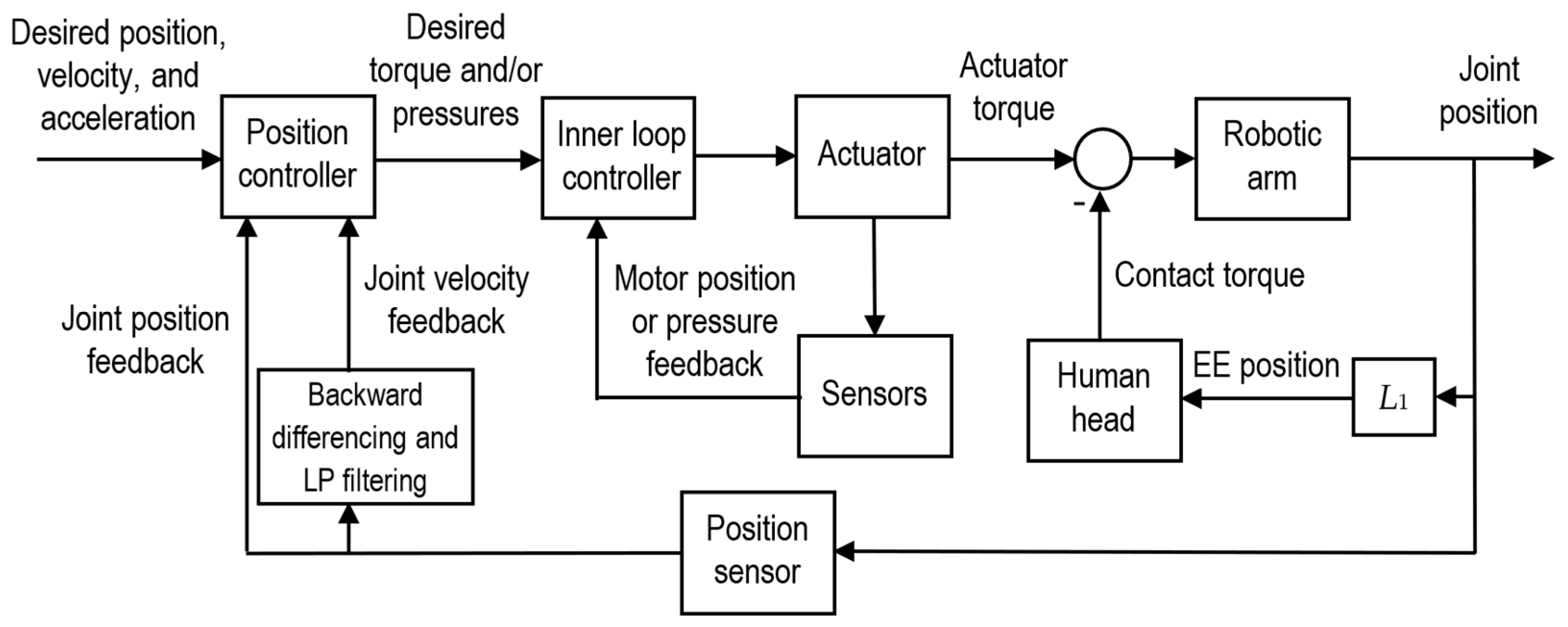
The general system structure, consisting of the control system, actuator, robot, and human head, is shown in Figure 1. The desired joint position, velocity, and acceleration, as well as the position and velocity feedback, are input into the position controller. The position controller outputs the desired torque and/or the desired pressures (which are required with the PA and HPEA). The inner loop controller controls the actuator’s output torque. With the SEA, it uses motor and joint position feedback. With the PA and HPEA, it uses pressure feedback. A CEA typically uses a motor driver to control the output torque in an open-loop manner and does not employ torque feedback. The contact torque caused by the contact force between the EE and the head (when that contact occurs) is subtracted from the actuator’s output torque. Friction torque (not shown) also reduces the torque that drives the arm. The remainder of the blocks represent the sensors that provide feedback to the controllers.
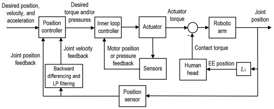
Figure 1.
Structure of the system.
3. System Modeling
3.1. Robotic Arm Dynamics
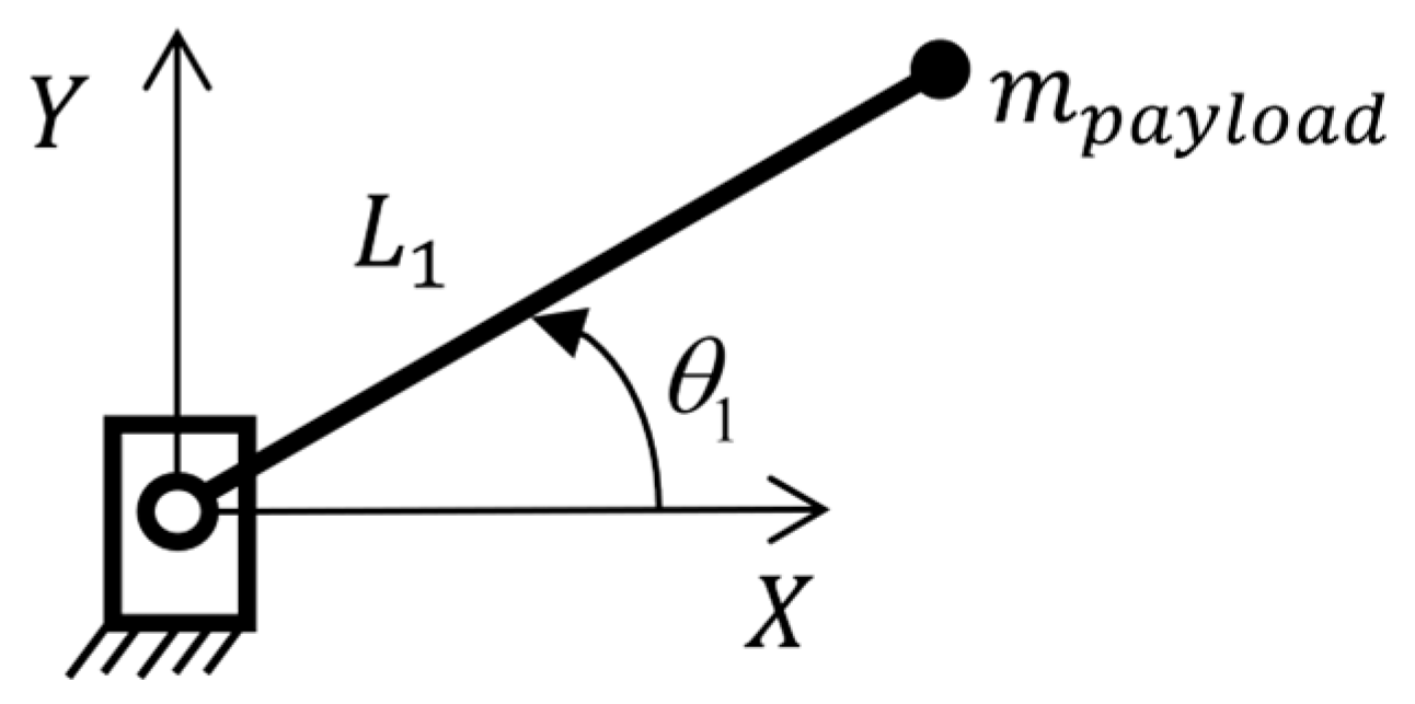
The robotic arm model is shown in Figure 2. Joint 1 rotates the arm in the horizontal plane shown. The mass of the payload carried by the robot is termed , and is the distance from joint 1 to the EE. The inertia of all of the links (and other joints) about joint 1 is termed .
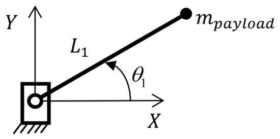
Figure 2.
Model of the robotic arm rotating about joint 1.
Taking the torques from contact with the human’s head, , into consideration, the dynamics of the robotic arm are given by:
where is the actuator torque, is the friction torque, is the combined moment of inertia of links 1–6, the payload, and the actuator; and is the angular acceleration of joint 1. As will be seen in the following sections, the equation for depends on the actuator being used.
3.2. Conventional Electric Actuator
The CEA used with robot joints consists of a DC motor rigidly coupled to a transmission. Typically, the transmission is a harmonic drive transmission (HDT) since they are lightweight and do not suffer from backlash. The structure of the CEA is shown in Figure 3. The desired actuator torque, , is input into the motor driver which controls the current such that the motor outputs a torque of . This torque is multiplied by the HDT gear ratio, , to produce the actuator torque, . The HDT also magnifies the friction torque. The equation for the actuator torque is simply:

Figure 3.
Schematic of the CEA.
Since the output shaft of the HDT is rigidly coupled to link 1 and only joint 1 is moving, the inertias of the motor and links 1–6 are combined in the dynamics. The motor inertia, , friction torque, , and gear ratio, , are included in the robot dynamics as follows:
where the value of for the CEA is:
The motor friction torque in (2) is modelled as a combination of Coulomb friction (representing both static and kinetic friction) and viscous friction. Its equation is:
where is the angular velocity of the motor, is the Coulomb friction torque, and is the coefficient of viscous friction.
3.3. Series Elastic Actuator
With an SEA, the rigid connection between the output shaft of the transmission and the link is replaced by a torsional spring, so the transmission and the link are not rigidly coupled. With this actuator, the robot dynamics are given by:
where the value of for the SEA is:
Assuming the spring’s mass is negligible, the actuator torque is simply:
where is the spring’s stiffness. The acceleration of the motor is given by:
where the motor friction torque, , can be calculated using (5).
3.4. Pneumatic Actuator and Hybrid Pneumatic–Electric Actuator
Schematic diagrams for a PA and a HPEA are given in [7,10], respectively. Equation (1) may be used to represent the robot dynamics for both the PA and HPEA. The equations in this section are based on the models presented in [10,12]. The PA consists of two pneumatic cylinders rotating the output shaft using a dual rack and pinion mechanism. The output shaft is directly coupled to the arm. The inertias of the pistons, rods, and gears are negligible compared to the arm’s inertia, so is given by (7).
Similarly, for the HPEA, the motor is directly coupled to the arm and its inertia is negligible compared to the arm’s inertia, so (7) applies again. The HPEA’s torque is given by:
where is the torque from its electric motor, and is the torque from its pneumatic actuator. With the PA, . The pneumatic torque for both the PA and HPEA is given by:
where is the pinion gear’s pitch radius, is the PA force (provided by the two cylinders working together), and:
where is the cross-sectional area of each PA chamber group (CG); and , are the pressures inside CGs 1 and 2, respectively. The dynamic equation for each CG is:
From this equation the derivative of pressure can be written as:
where is the mass flowrate into the CG, k is the ratio of specific heats for air, R is the universal gas constant, T is the air temperature, is the CG pressure, and is the CG volume. The CG volumes are defined by:
where V01 and V02 are CG volumes when . Modeling air as an ideal gas, can be obtained by:
where is the orifice area for each valve, and is obtained using:
where is the pressure upstream of the valve, is the downstream pressure, is the discharge coefficient of the valve, and are dependent on the ideal gas constant and specific heat ratio for air, and is the critical pressure ratio that differentiates subsonic and sonic flows inside the valve. Assuming the supply pressure, , and atmospheric pressure, , are constant:
The orifice area for each valve is given by:
where are the valve input voltages, and is a valve-dependent constant.
Finally, the friction force in (1) is given by:
where is the Coulomb friction force, is the static friction force, and is the viscous friction force coefficient.
4. Dynamic Models of Human–Robot Collisions
4.1. Constrained Impact
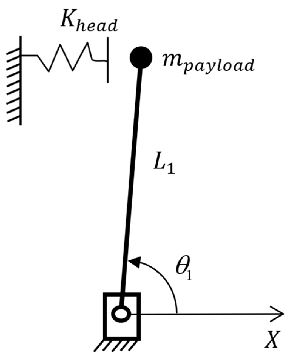
A model for the constrained impact scenario described in Section 2 is presented in this section. The simplified model for the human’s head at the impact location is a linear spring with its far end fixed, as is shown in Figure 4.
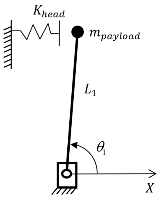
Figure 4.
Human head model for constrained impact.
Assuming the link is infinitely stiff, the contact force is given by:
where and is the position of the head (which corresponds to the right end of the spring in the figure). Assuming the spring’s deflection is small, the contact torque for this head location is simply:
Another case occurs when a compliant covering made of elastomeric foam is added to the robot. We assume the foam may also be modelled as a spring, with a stiffness of . In this case, when the impact happens, the spring stiffness can be replaced by the stiffness of two springs in series:
However, a real compliant covering will have a lower thickness limit where it cannot be further compressed so it becomes effectively rigid. For a compliant covering with an uncompressed thickness of and a lower thickness limit of , the contact force is given by:
where is the compressed thickness of the covering. It is given by:
4.2. Unconstrained Impact
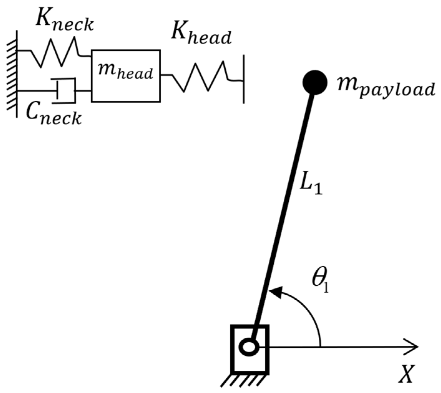
The second impact type studied in this paper occurs when the robot hits a person’s unconstrained head. Since the head can move during the impact, is no longer a fixed value, and the model must include the head’s mass and the neck dynamics. Using the model from [13], the neck can be simplified as a spring with the stiffness in series with a damper with the damping coefficient , as is shown in Figure 5. The acceleration of the head is then:
where is the equilibrium position of the head and is the mass of the head.
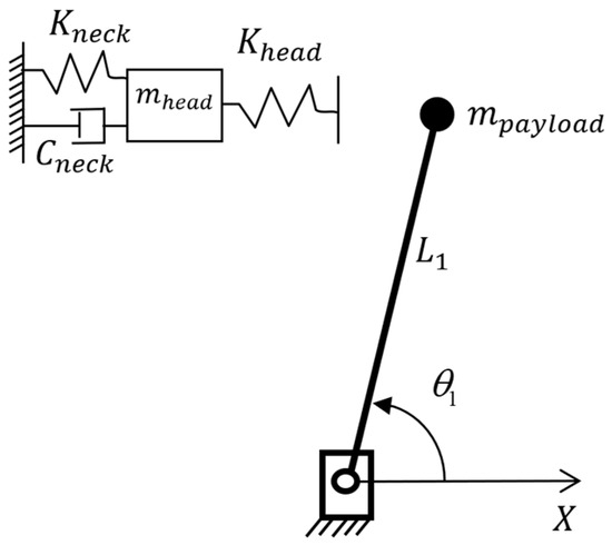
Figure 5.
Human head and neck model for unconstrained impact.
5. Actuator Controllers and Robot Collision Reaction Strategies
5.1. Controller for the Conventional Electric Actuator
We begin by dividing the commanded motor torque into two parts. The model-based feedforward part is:
where is the estimated value of , and is the desired angular acceleration of the joint. The feedback part is:
where and are the desired joint angle and desired angular velocity of the joint, respectively; is the sensed joint angle; and is the joint velocity estimated by backward differencing and low-pass filtering . Combining the feedback and feedforward parts, the equation for the commanded motor torque, , is:
where , and is the estimated friction torque which is given by:
In order to tune the controller systematically, further derivation is necessary. First, after transforming the time domain equations to frequency domain equations, with an abuse of notation, (30) can be rewritten in the form:
When , from (3):
Assuming the model is perfect, we have: . Then, by combining Equations (2), (32) and (33), we obtain the position error equation:
After equating the coefficients of this error equation with the standard second-order form , the equations for the controller gains are obtained as follows:
where is the desired closed-loop natural frequency, is the desired closed-loop damping ratio, and is the desired closed-loop bandwidth.
5.2. Controller for the Series Elastic Actuator
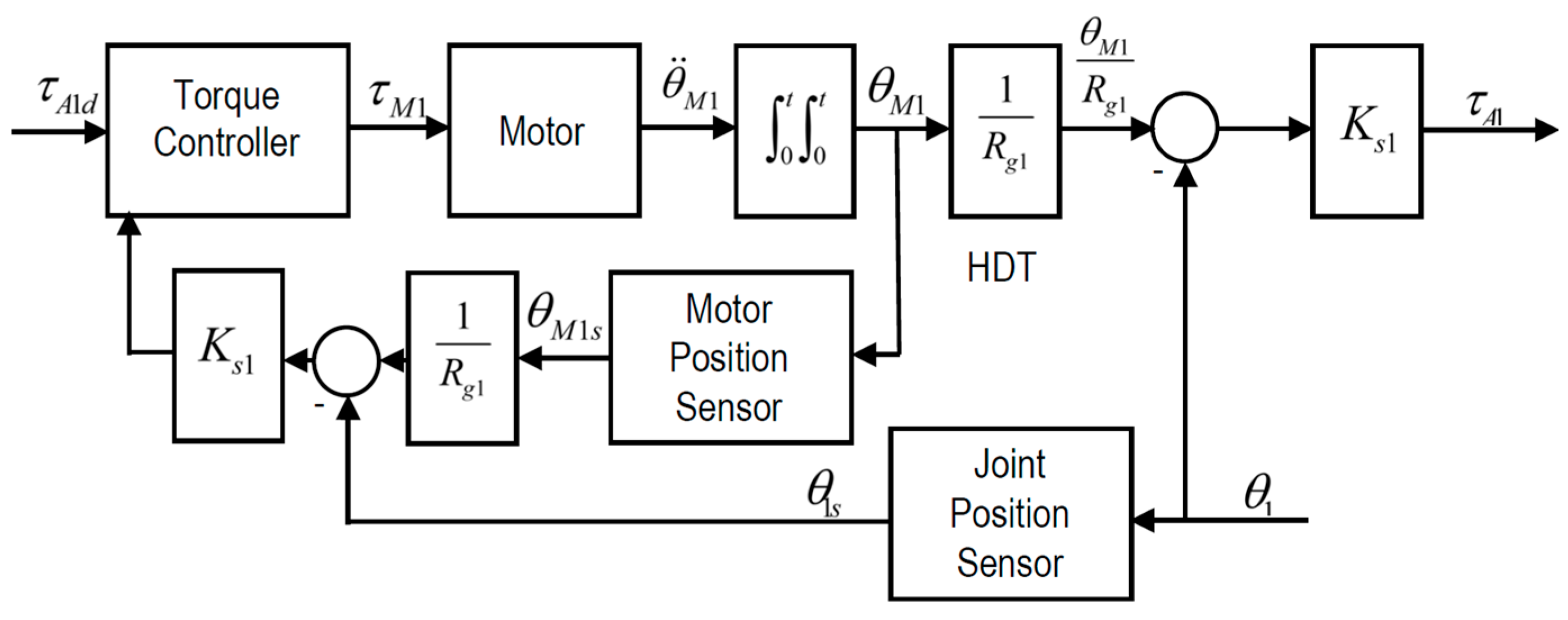
The SEA is controlled using an outer position control loop with an inner torque control loop. The torque control loop in this section is based on the force control loop presented in [1]. Its structure is shown in Figure 6.
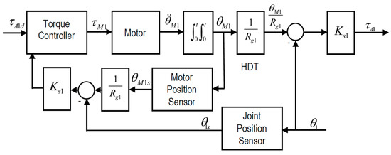
Figure 6.
Structure of the torque control loop for the SEA.
The position control loop uses this common PD plus acceleration feedforward controller:
where and are the proportional and derivative gains, respectively. The PD plus torque feedforward and acceleration feedback torque controller is:
where ; and are the proportional and derivative gains, respectively; is the inertia compensation gain; is the estimated motor inertia; and is the estimated joint angular acceleration. Note that is calculated by backward differencing and first order low-pass filtering . Equation (31) is used to calculate the estimated friction torque, , the same as with the CEA. The torque derivatives used in (39) may be obtained as follows:
Note that we did not include the term in the equation since the third derivative of contains excessive high frequency noise.
In order to tune the controller systematically, a derivation similar to the one conducted for the EA can be conducted for the SEA. First, the time domain equations are transformed to frequency domain equations. Then, with an abuse of notation, can be written in the form:
Next, can be written as:
Substituting Equation (44) into (43), with , and assuming we know the motor inertia perfectly (i.e., ), we obtain the torque error equation:
Equation (38) can then be written as:
Assuming the model is perfect, we have: , then combining (6) (with ) and (46) gives the position error equation:
After equating the coefficients of the error equations, (45) and (47) with the standard second-order form, the equations for the controller gains are obtained as follows:
where and are the desired closed-loop natural frequency and damping ratio of the outer position control loop, respectively; and and are the desired closed-loop natural frequency and damping ratio of the inner torque control loop, respectively.
5.3. Controllers for the Pneumatic Actuator and Hybrid Pneumatic Electric Actuator
The PA will be controlled using an outer loop position controller with inner loop pressure controllers for each CG [10]. The PD plus acceleration feedforward position controller is:
where and are the proportional and derivative gains, respectively; and is obtained using:
where:
and and are the sensed pressures of CG 1 and 2, respectively.
When the HPEA is used, the position controller for the electric motor is:
where ; and and are the proportional and derivative gains, respectively.
In order to tune the position controllers systematically, a derivation similar to the one for the SEA was performed. The controller gains are then given by:
where and are the desired closed-loop natural frequency and damping ratio of the outer position control loop, respectively; and and are the desired closed-loop natural frequency and damping ratio of the HPEA motor’s position control loop, respectively.
The equation for the inner loop model-based pressure controller used with the jth CG, , are as follows:
where is the mass flowrate into the jth CG; and are the desired pressures for CG 1 and 2, respectively; and and are the proportional and integral gains, respectively.
Since the inner loop controller is PI-based rather than PD-based, the equations for systematically obtaining the controller gains must be derived differently. First, the model of the CG pressure dynamics is rewritten as follows:
where , and . The controller equation may then be rewritten as:
Assuming , and substituting (71) into (70) gives:
Defining and transforming (72) to the frequency domain, we obtain:
Finally, equating the coefficients of (73) with the standard second-order form, the following equations for the controller gains are obtained:
where and are the desired closed-loop natural frequency and damping ratio of the inner pressure control loop, respectively.
5.4. Collision Reaction Strategies
Collision detection and reaction is another method for potentially reducing the impact force. We investigated two collision reaction strategies. The first strategy is to turn the actuator off immediately after detecting the collision. This strategy is abbreviated as “TAO”. The second strategy is to rapidly withdraw the arm when the collision is detected. This second strategy is abbreviated as “WTA”. These strategies were used with all of the actuators, but the way they were applied depended on the specific actuator. For the CEA and SEA, we set when using TAO and set with WTA. For the PA, we set with TAO and and with WTA. With the HPEA, we additionally set with TAO and with WTA. Of the two strategies, the WTA is riskier since it involves the actuator applying torque to the arm, which could make the collision worse or cause a secondary collision if the software or hardware malfunctions.
6. Motion and Collision Simulations
6.1. Simulation Overview
The simulations were programmed in Matlab using m code. The velocity Verlet integration method was used since it is computationally efficient and provides greater numerical stability and accuracy than the more commonly used Euler integration method. A short integration timestep of s was used to further improve the accuracy. The desired trajectory used for all of the simulations was designed to have large accelerations and velocities during the first 2 s to test each actuator’s ability to track a challenging motion trajectory. After 2 s, the desired joint velocity was set to rad/s. The human’s head was located such that the collision happened after 2 s. This means the desired linear velocity of the EE was 0.25 m/s when the collision occurred. The value of 0.25 m/s was chosen since it is the highest speed permitted by the International Organization for Standardization (ISO) robot safety standard (ISO 10218-1:2011 [18]) when a human is within reach of a robot arm. A quintic spline trajectory was used since it produces the smooth jerk trajectory that is required by some of the controllers. At the times t = 0, 0.5 s, 1 s, 1.5 s, and 2 s the desired joint angles in rad were: 1.257, 0.785, 0.393, 0.785, and 1.471. The desired joint angular velocities in rad/s at these times were: 0, , 0, and . The desired accelerations at these times were zero. The minimum and maximum desired EE linear velocities were −1.8 m/s and 1.8 m/s. The magnitude of the maximum desired EE linear acceleration was 6.8 m/s2.
The parameters used in the simulations were as follows:
- Robot parameters ( are the same as a UR5 robot): [19], (derived from the equations in [19] and the parameters in [20]), and
- CEA and SEA parameters ( are the same as joint 1 of the UR5 robot): , [20], [20], [20], and [20].
- PA and HPEA parameters: (for two SMC CQ2A40TN-75DMZ cylinders), (Enfield LS-V05s proportional valve), and (MTI Torque Systems, T0852J0001, brushless servomotor).
- Controller parameters: , all desired and 0.001 s sampling period.
- Human head and neck parameters: [21], [21], [13], and [13].
- Initial thickness and lower stiffness limit of the compliant covering: and .
- Stiffness of the compliant covering used to obtain the results in Figures 13 and 14: .
6.2. Sensor Noise and Modeling Error
To make it more realistic, the simulation included joint angle encoder quantization noise, pressure sensor noise (with the PA and HPEA), and a mismatch between the friction model used by the model-based controllers and the simulated robot.
The chosen encoder was a QR-12 optical encoder made by Quantum Devices. It is a high-resolution encoder, with a resolution of 80,000 counts/rev. Its quantization noise was simulated by setting the sensed joint angle equal to: , where round() is the standard rounding function. Regarding the pressure sensors, the sensed pressures were obtained by adding 0.1% uniformly distributed random noise to the ideal pressures. This noise level is typical for the pressure sensors used with the PA and HPEA.
To introduce friction mismatch, the friction parameters used by the model were 25% smaller than the values used by the plant. Specifically, for the electric motor and SEA, was estimated as , was estimated as ; and for PA and HPEA, , , and were estimated as , , and . Additional error in the controllers’ friction compensation terms was caused by their use of the estimated velocities.
6.3. Simulation Results and Discussion
6.3.1. Motion Control
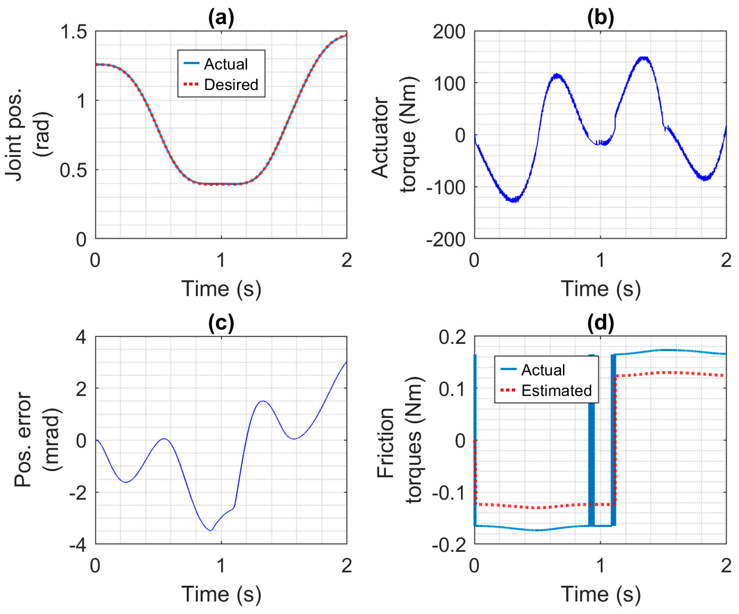
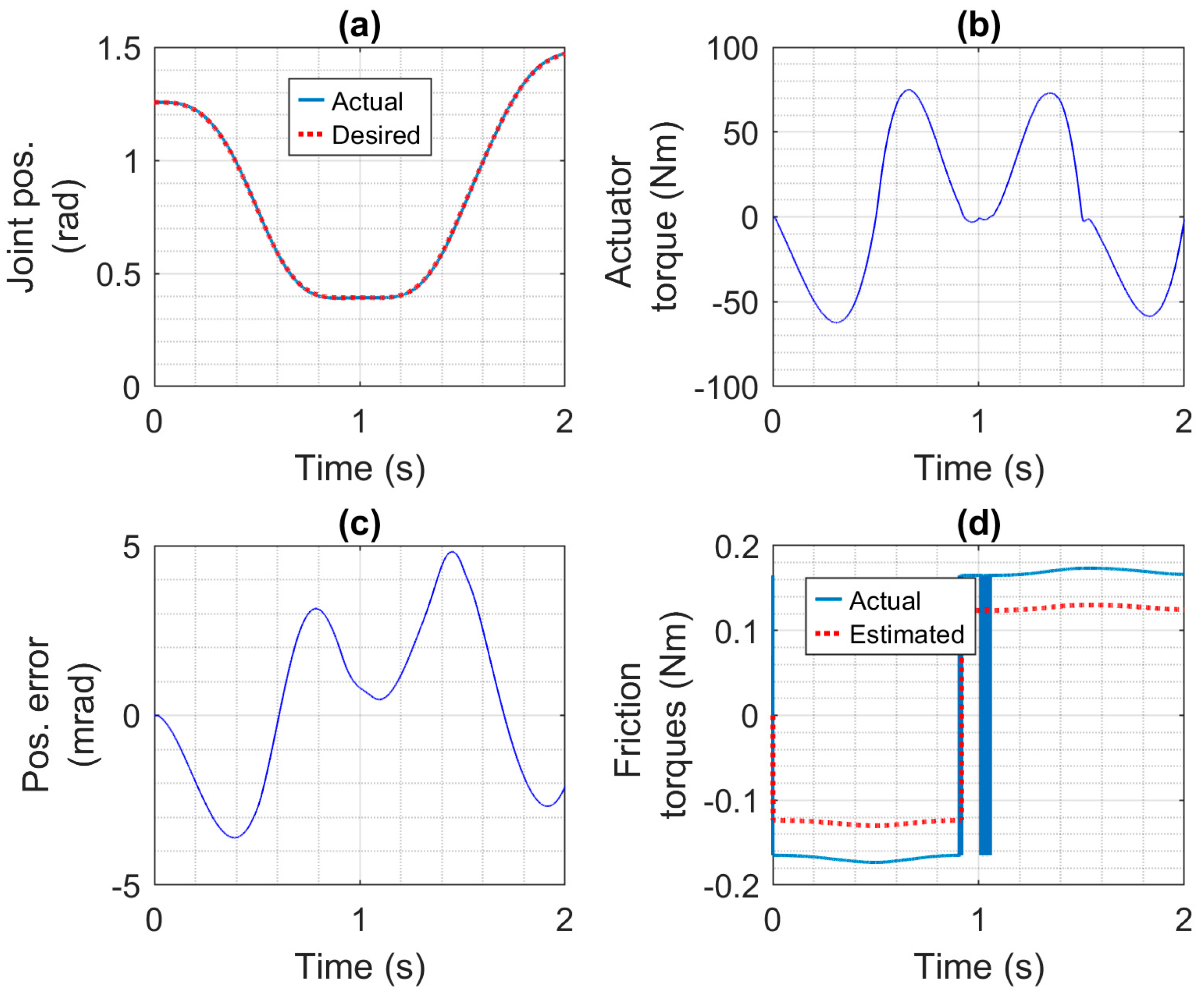
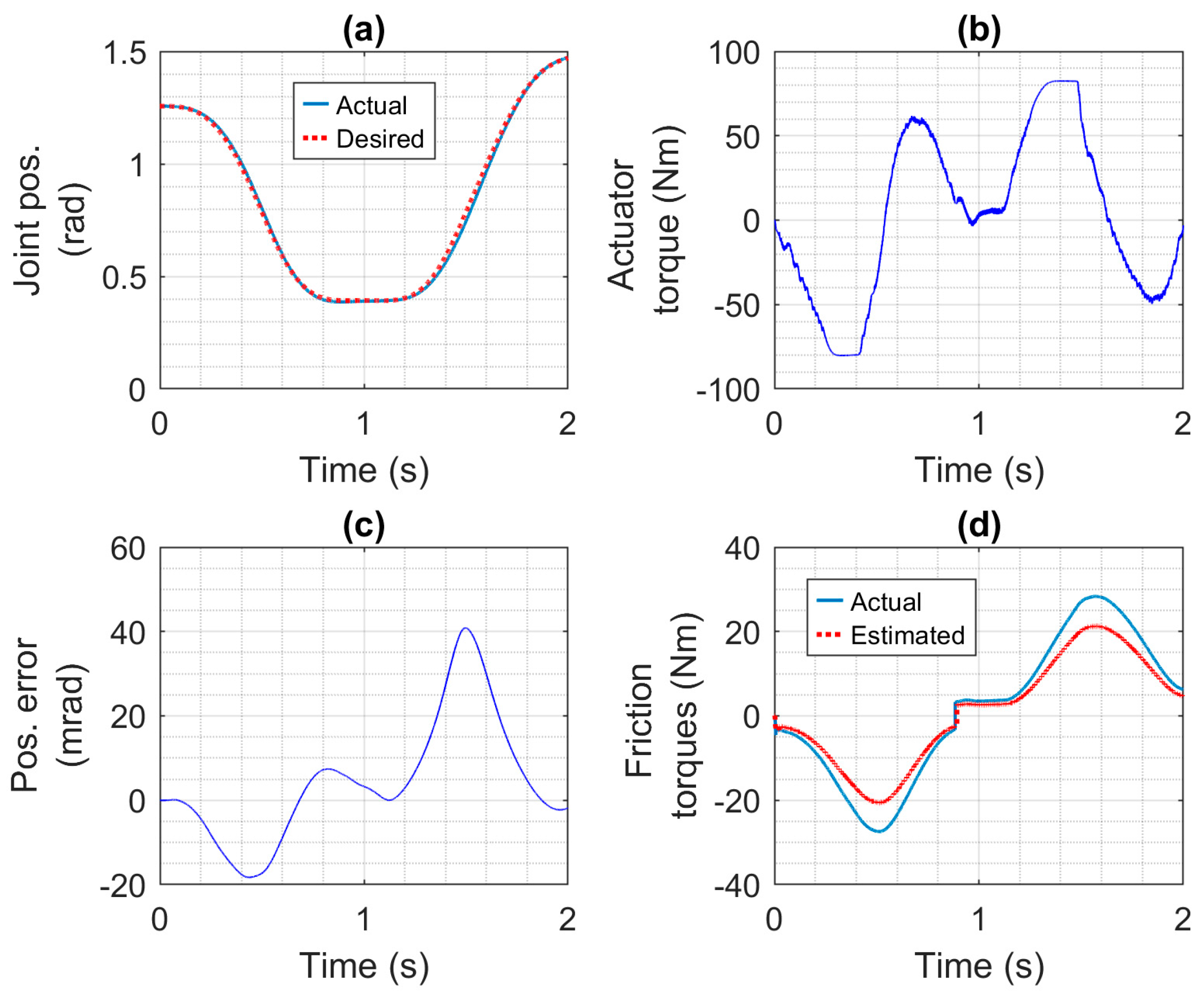
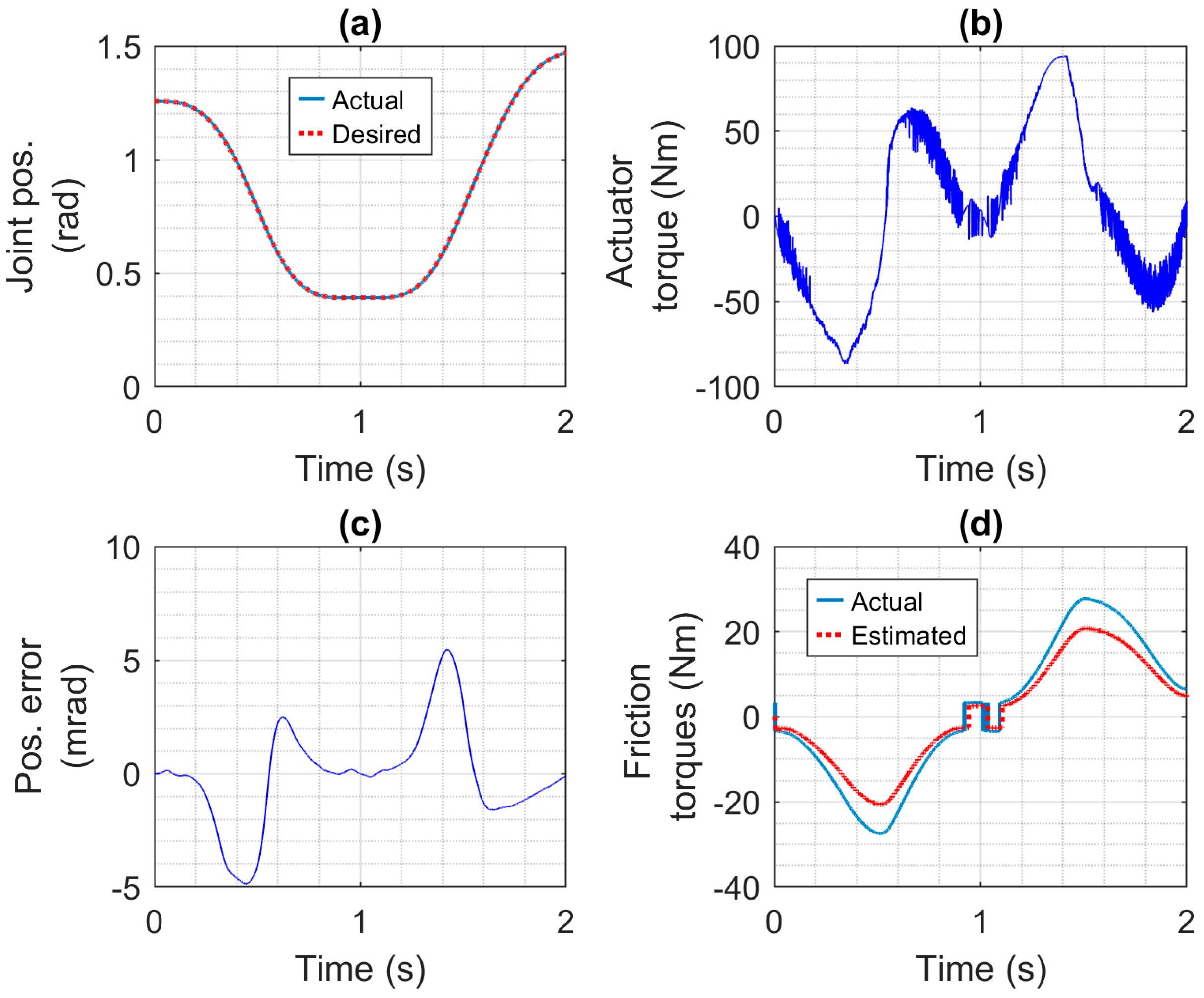
The motion control performance of the four actuators was studied first, followed by a study of the actuators, compliant covering, and collision reaction strategies effects on safety. The motion control results for the robotic arm driven by the CEA, SEA, PA, and HPEA are shown in Figure 7, Figure 8, Figure 9 and Figure 10, respectively. Only the first 2 s of the simulations, where the demanding motion trajectory occurs, are studied in this section. Note that the controllers for all of the actuators were tuned (using the equations given in Section 4.1 and Section 4.2) with the same desired closed-loop bandwidth and damping ratio values (given in Section 5.2). The CEA has the best performance. Its tracking errors are less than 3.5 mrad and its RMSE is 1.7 mrad. The SEA has the third-best performance with a RMSE of 2.5 mrad and errors less than 5 mrad. The motors and gear ratios used with these actuators were identical, so they are not the reason for the difference in performance. Comparing the CEA and SEA torques shown in Figure 7b and Figure 8b, the CEA torque has a high frequency component that is missing from the SEA torque. This high-frequency torque (which was filtered out by the SEA’s spring) is the main reason for the CEA’s better performance. The PA has the worst performance, with errors as large as 40 mrad and a RMSE of 15.2 mrad. This is partly due to the much larger difference (i.e., about 7 Nm) between the estimated friction torque (used by its controller) and the actual friction torque shown in Figure 9d, when compared to the differences shown in Figure 7d and Figure 8d. The larger friction torque is caused by the seals of the PA. Another reason for its poor performance is that the PA is not able to produce enough torque to produce the desired acceleration in the presence of this friction torque. In contrast, the HPEA produced the second-best performance (with a RMSE of 2.2 mrad and errors of less than 5.5 mrad) even though its friction torque is almost identical to the PA’s. The reason is the small additional torque (i.e., less than = 11.6 Nm) provided by the HPEA’s electric motor. This difference may be observed by comparing the curves in Figure 9b and Figure 10b.
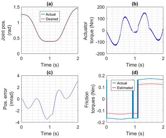
Figure 7.
Motion control results for the robotic arm driven by the CEA: (a) desired and actual joint positions, (b) actuator torque, (c) joint position error, and (d) estimated and actual friction torques.
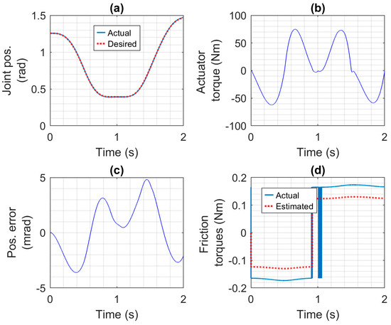
Figure 8.
Motion control results for the robotic arm driven by the SEA: (a) desired and actual joint positions, (b) actuator torque, (c) joint position error, and (d) Estimated and actual friction torques.
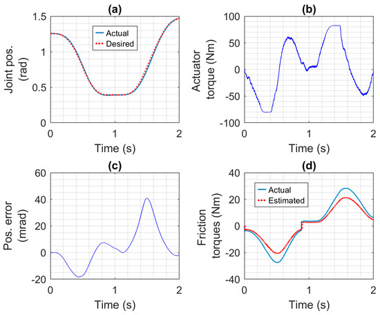
Figure 9.
Motion control results for the robotic arm driven by the PA: (a) desired and actual joint positions, (b) actuator torque, (c) joint position error, and (d) estimated and actual friction torques.
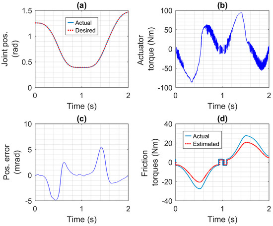
Figure 10.
Motion control results for the robotic arm driven by the HPEA: (a) Desired and actual joint positions, (b) actuator torque, (c) joint position error, and (d) estimated and actual friction torques.
6.3.2. Collision Safety
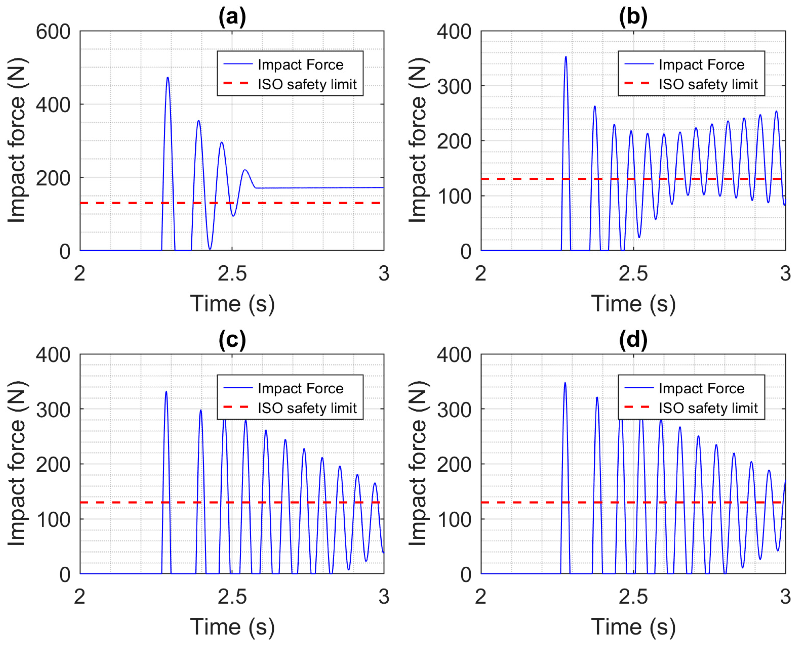
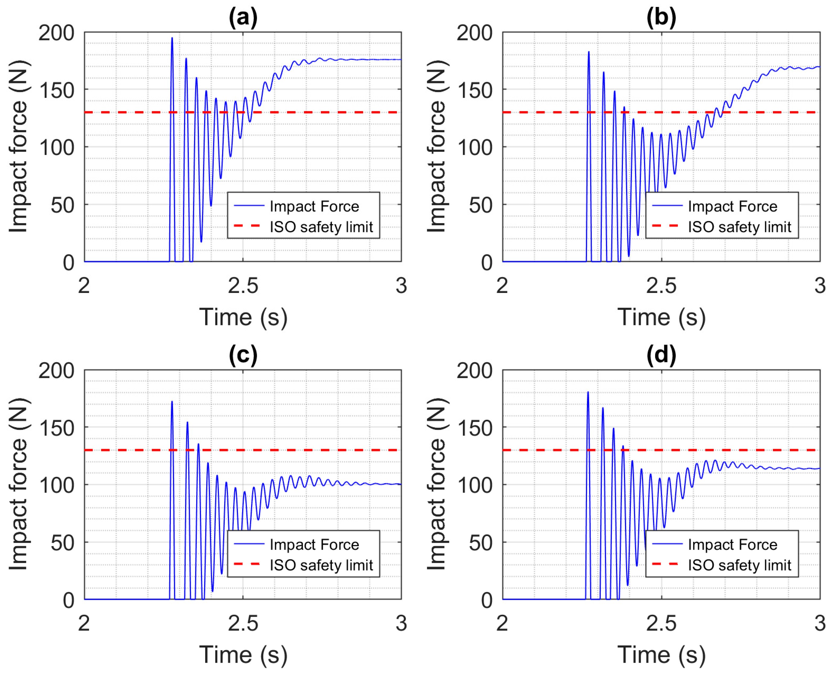
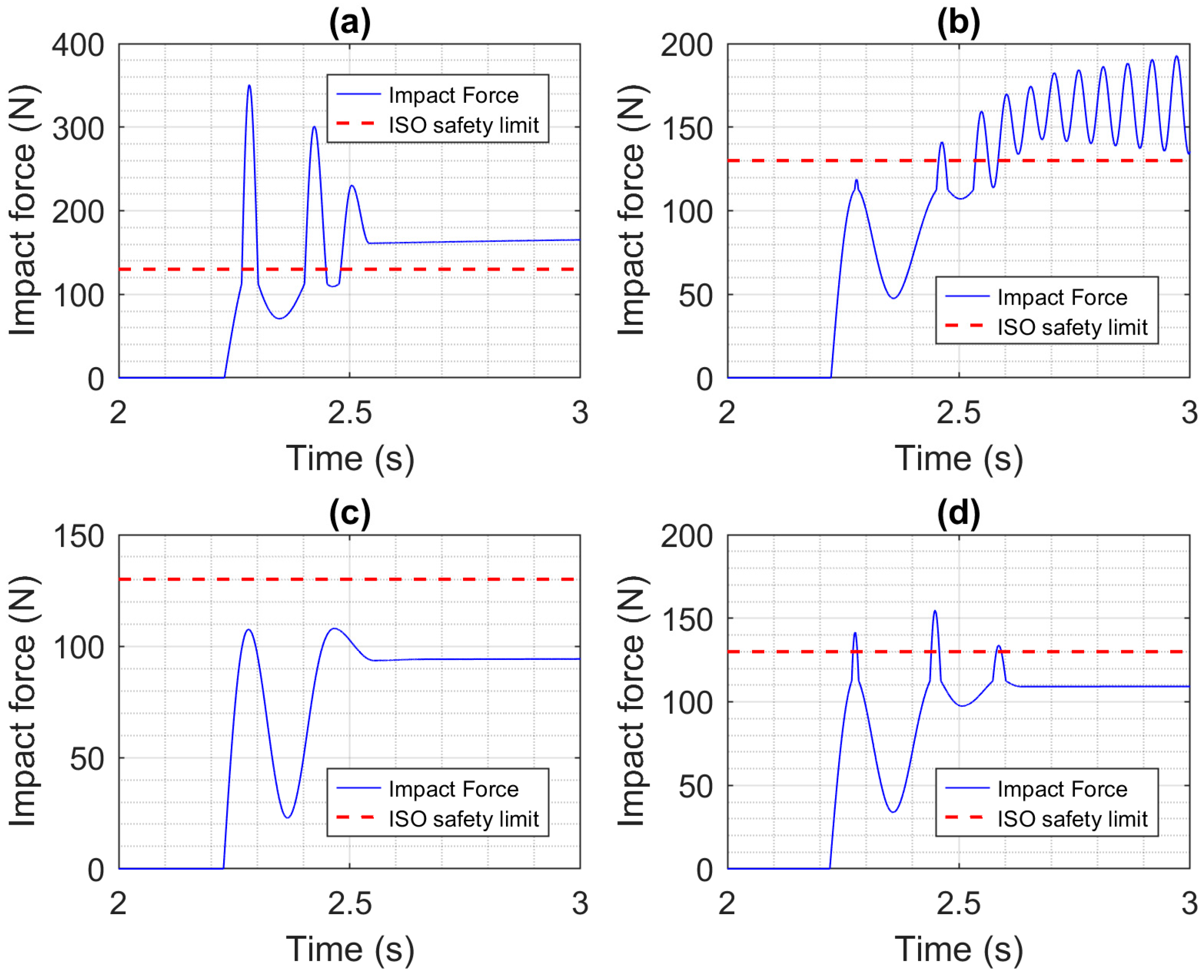
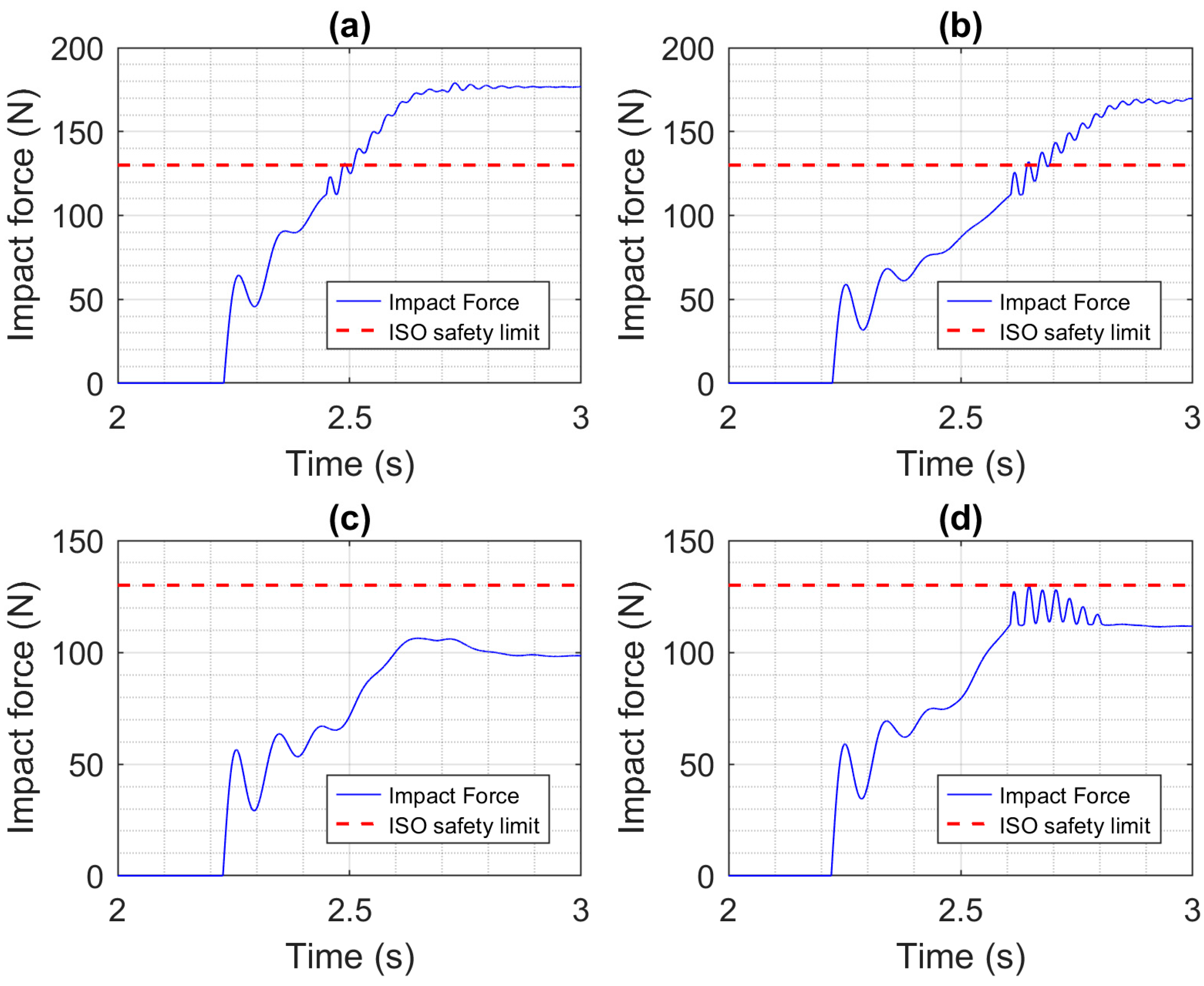
The safety of collisions without the robot using collision detection and reaction is discussed here. The impact forces for the four actuators and a constrained impact of the EE with the head, with no compliant covering added to the robot, are plotted in Figure 11. Only the last second of the simulation is shown since that is when the impact occurred. Since the robot kept trying to follow the desired trajectory and move its EE at 0.25 m/s, the impact forces do not diminish to zero. Using the CEA produced the largest MIF of 474 N, while using the PA produced the smallest MIF of 332 N. While this relative decrease in MIF matters, it is important to note that the ISO standard establishing safety requirements for collaborative robot applications (ISO/TS 15066:2016 [21]) specifies that the maximum force that should be applied by a robot to a person’s head is 130 N. According to this 130 N limit, all of the impacts shown in Figure 11 are unsafe. The impact force results with the impact type changed from constrained to unconstrained are shown in Figure 12. The compliance of the neck clearly reduced the forces significantly and also allowed the oscillations to decay in roughly 0.5 s. Even so, the MIFs are all well above the 130 N limit. The results for the constrained and unconstrained impacts when the 1 cm-thick compliant covering has been added to the robot are shown in Figure 13 and Figure 14, respectively. Comparing Figure 11 and Figure 13, we can see that adding the compliant covering has both reduced the magnitude of the forces and reduced the duration of their oscillations, with the exception of the SEA. With the SEA, the oscillations continue to grow until they reach a limit cycle with an MIF of 316 N (not shown in the figure). This is caused by energy being passed between the SEA’s motor and spring and between the spring models of the compliant covering and head, which leads to a mechanical resonance. Unfortunately, in Figure 13, the MIFs for all actuators still exceed the 130 N limit. In Figure 14, when compared to the results in Figure 12, we can again see reduction produced by adding the compliant covering. The MIFs for the CEA and SEA still exceed the 130 N limit, but the MIF for the PA is only 106 N, so it is well below the limit. The MIF for the HPEA is 129 N. It is less safe than the PA due to the torque added by its electric motor, but its MIF still does not exceed the 130 N limit.
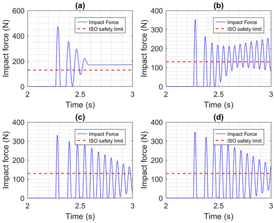
Figure 11.
Impact force results for a constrained head impact when no compliant covering or collision reaction is used. The actuators used are: (a) CEA, (b) SEA, (c) PA, and (d) HPEA.
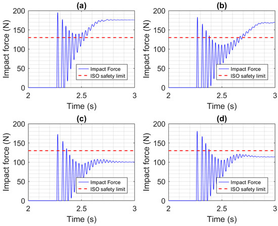
Figure 12.
Impact force results for an unconstrained head impact when no compliant covering or collision reaction is used. The actuators used are: (a) CEA, (b) SEA, (c) PA, and (d) HPEA.
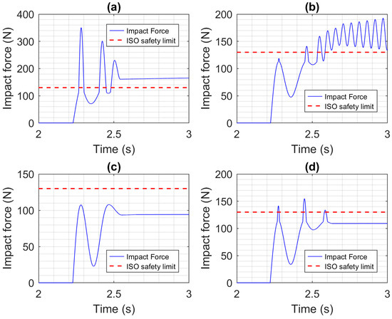
Figure 13.
Impact force results for a constrained head impact when a compliant covering is added to the robot, with no collision reaction. The actuators used are: (a) CEA, (b) SEA, (c) PA, and (d) HPEA.
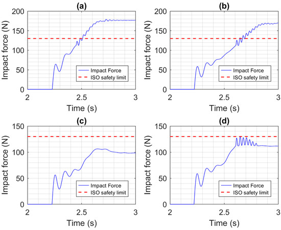
Figure 14.
Impact force results for an unconstrained head impact when a compliant covering is added to the robot, with no collision reaction. The actuators used are: (a) CEA, (b) SEA, (c) PA, and (d) HPEA.
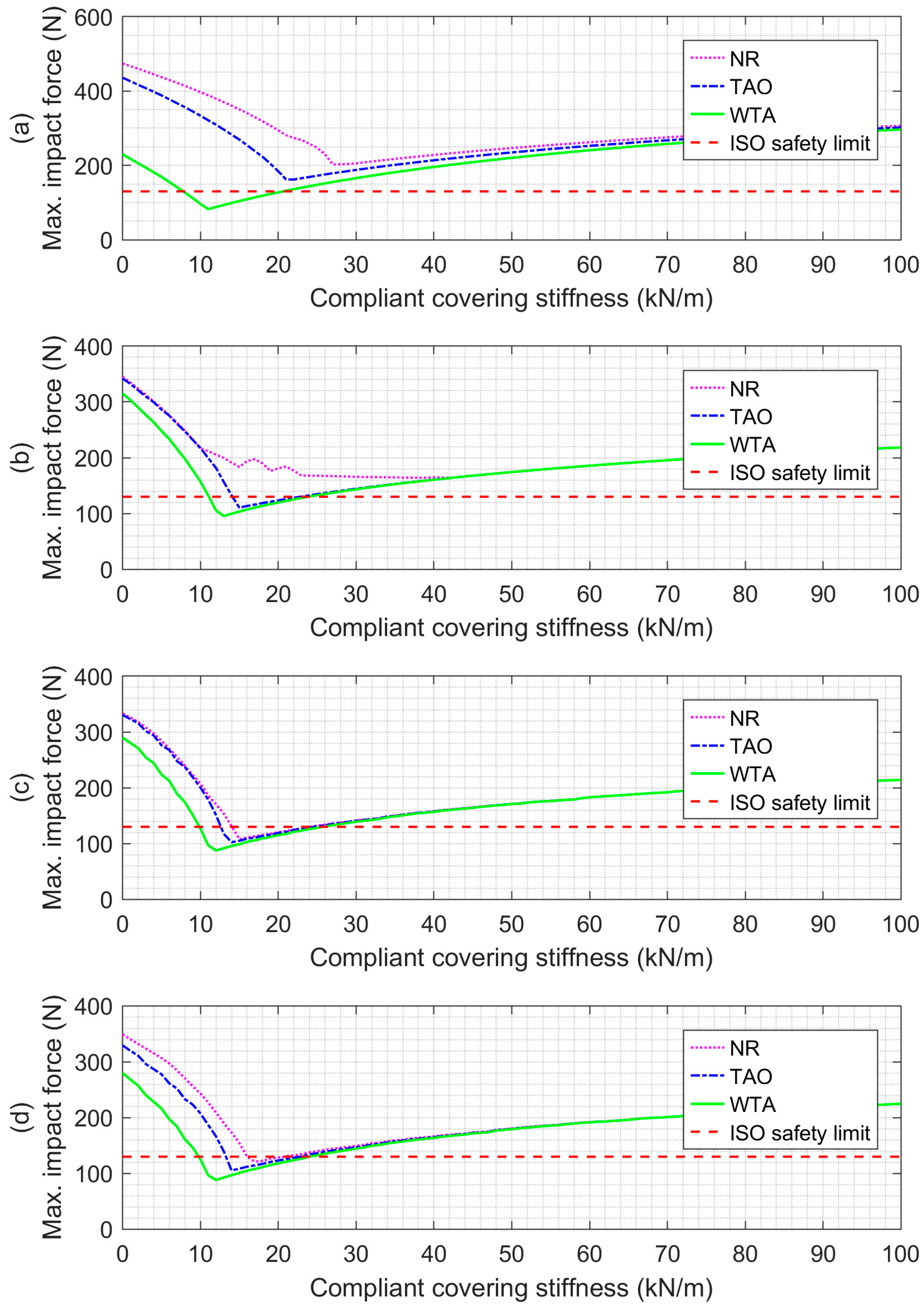
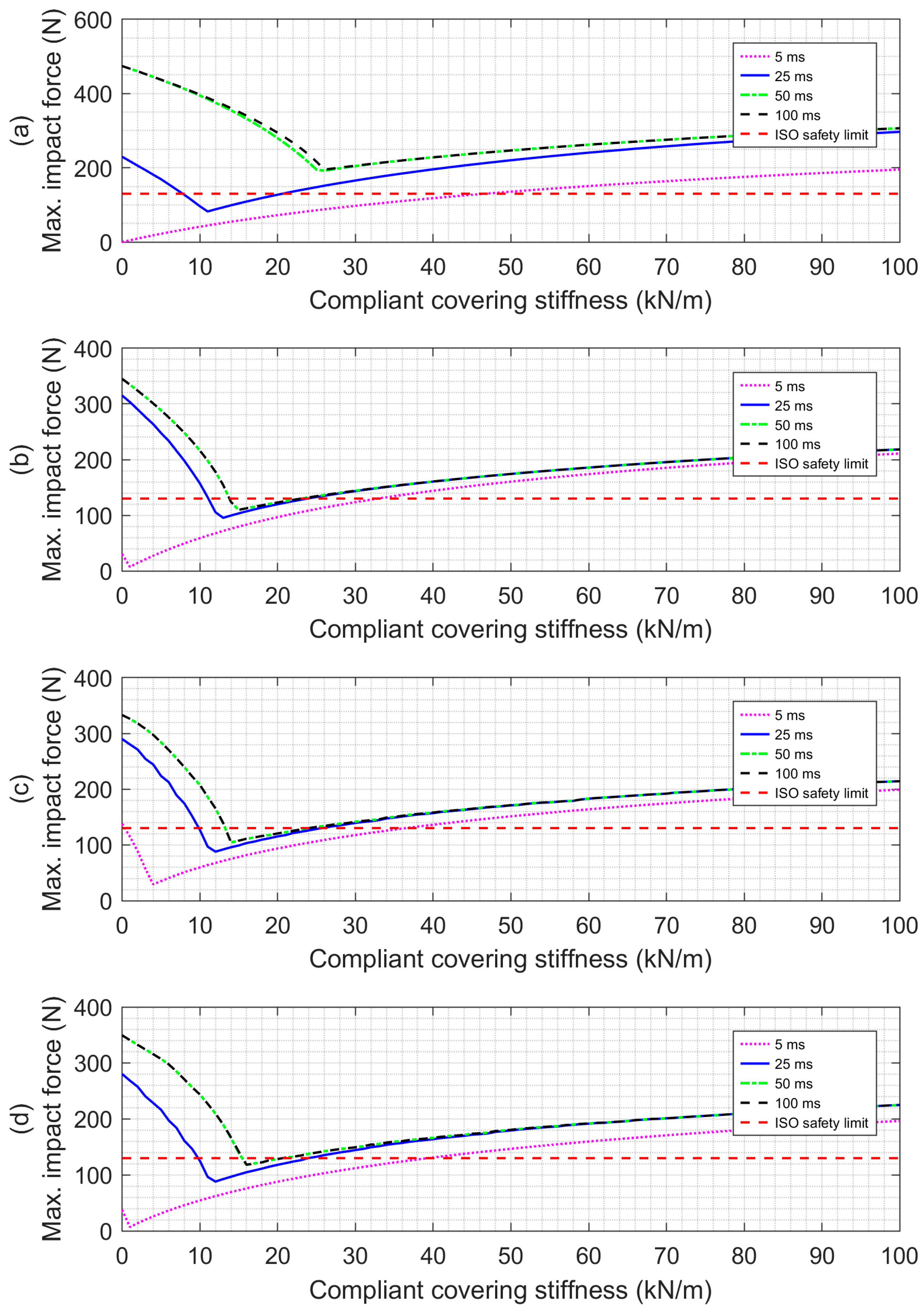
A second series of simulations was performed to study the potential safety benefits of collision detection and reaction. The combination of compliant covering with collision detection and reaction was also investigated. Since the MIF for the unconstrained impacts without collision reaction can be less than the 130 N safety limit (specifically when the robot uses a compliant covering and is driven by either the PA or HPEA), only constrained impacts are studied in the remainder. Rather than showing many impact force vs. time plots, the MIF values are plotted vs. the compliant covering stiffness in Figure 15 for the four actuators when using no reaction (NR) to the collision, the TAO reaction strategy, and the WTA reaction strategy. The collision detection and reaction delay (DRD) was set to 25 ms. With all of the actuators, these results show that there is an optimal value of the compliant covering stiffness that minimizes the MIF. This may seem unintuitive since less stiffness would normally reduce the impact force. The reason for the MIF increasing with less stiffness than its optimal value is that the covering reaches its lower thickness limit during the impact, so it stops absorbing the kinetic energy of the collision. The curves in part (a) show that the CEA benefits the most from employing collision detection and reaction. Comparing the MIF values at the optimal stiffnesses, the TAO strategy reduces the MIF from 202 N to 162 N, and the WTA strategy reduces it further to 82 N. The curves in part (b) show that the TAO and WTA are also necessary for the MIF produced by the SEA to be reduced below the 130 N limit. The reductions with the other actuators are smaller but are not insignificant. As shown in part (d), using the TAO strategy with the HPEA reduced the MIF from 121 N to 105 N, and using WTA reduced it to 88 N. It is also interesting to note that the MIF for the PA (shown in part (c)) when using the WTA strategy was also 88 N. After determining the benefits of the WTA strategy when the DRD equaled 25 ms, we simulated collisions using WTA with other DRD values to see their influence on the collision safety. MIF vs. compliant covering stiffness curves for the four actuators with DRD values of 5 ms, 25 ms, 50 ms, and 100 ms are plotted in Figure 16. These curves show that the DRD value has a major influence on the effectiveness of the WTA strategy. Comparing the NR curves in Figure 15 to the curves in Figure 16 with DRD values of 50 ms and 100 ms, it can be observed that the WTA provides little or no reduction in the MIF for values of 50 ms or higher. The improvement with a DRD of 25 ms has already been discussed. The improvement when the DRD is reduced to 5 ms is much greater as long as the covering stiffness is chosen properly. The curves in parts (b)–(d) show that with this 5 ms DRD, the MIF can be reduced to almost zero when the optimal compliance covering stiffness is used with the SEA, PA, and HPEA actuators. When used with the CEA, the MIF is reduced to zero when a compliant covering with zero stiffness is used. This result requires further explanation. With a 1 cm covering thickness, contact with the covering happens when the head is less than 1 cm from the robot. With a DRD of 5 ms, the collision is detected, and the reaction begins 5 ms after the initial contact. When using the WTA strategy with the CEA, its maximum torque of 150 Nm is then applied to first decelerate the robot and then accelerate it away from the person’s head. Obviously, a covering with zero stiffness is impossible, but some form of proximity sensing on the robot could be used to detect when the head is within the 1 cm air gap between it and the robot. After the DRD, the robot’s rapid deceleration and acceleration with the CEA prevents physical contact from happening, which is why the MIF is zero. While the MIF reductions using the WTA strategy with a 5 ms DRD are impressive, it is important to note that a DRD of 5 ms is the shortest delay reported in the literature, and it was achieved by a state-of-the-art research robot [22]. The DRD values with other robots are likely to be 25 ms or more.
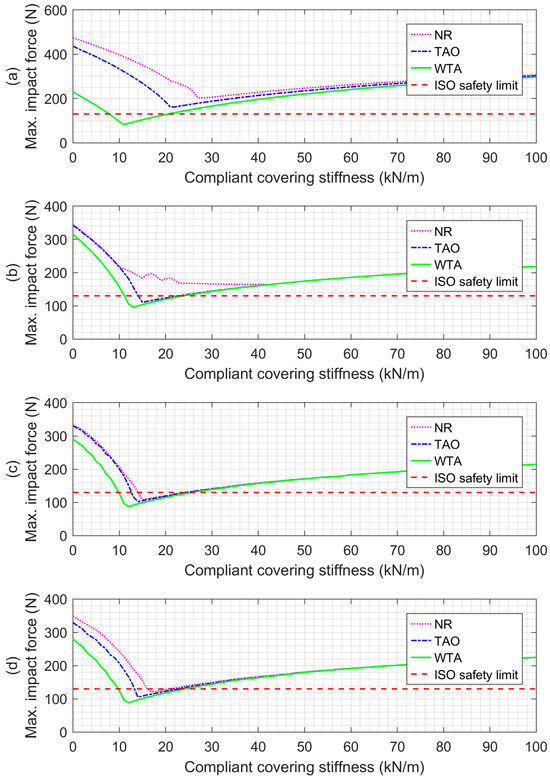
Figure 15.
MIF vs. compliant covering stiffness when using no reaction (NR) to the collision, the TAO reaction strategy, and the WTA reaction strategy. All results are for a constrained head impact with the collision DRD set to 25 ms. The actuators used are: (a) CEA, (b) SEA, (c) PA, and (d) HPEA.
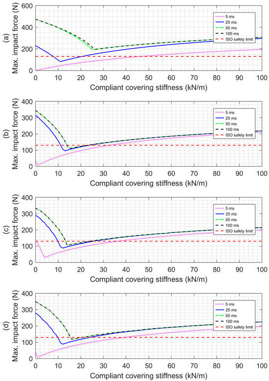
Figure 16.
MIF vs. compliant covering stiffness when using the WTA reaction strategy with DRD values of 5 ms, 25 ms, 50 ms, and 100 ms. All results are for a constrained head impact. The actuators used are: (a) CEA, (b) SEA, (c) PA, and (d) HPEA.
7. Conclusions
The motion control and safety of a robotic arm whose first joint was powered by four different actuators was simulated for a variety of cases, including: constrained/unconstrained head impacts, the addition of compliant covering, and the use of two collision detection and reaction strategies. To improve the fairness of the comparisons, all of the controllers were systematically tuned using the same desired closed-loop bandwidth and damping ratio. Several conclusions may be drawn from this study. In terms of motion control, the CEA had the best performance (RMSE = 1.7 mrad), followed by the HPEA (RMSE = 2.2 mrad), SEA (RMSE = 2.5 mrad), and PA (RMSE = 15.2 mrad). With the exception of the PA, the differences in RMSE are quite small.
Greater differences between the actuators were observed when their safety (in terms of the MIF values) was compared. When no compliant covering or collision reaction strategy was used, for both constrained and unconstrained impacts, the MIF values for all actuators exceeded the ISO’s 130 N safety limit. The addition of the 1 cm-thick compliant covering reduced the MIF values for the PA and HPEA below the safety limit, for both impacts. These results mean safe collisions are possible with the arm driven by either a PA or HPEA without requiring any collision detection or reaction strategy. This is significant since implementing a reliable collision detection and reaction system with a commercial robotic arm would be both difficult and costly, compared to adding a compliant covering. With a 25 ms DRD, the TAO and WTA collision detection and reaction strategies both reduced the MIFs for the CEA and SEA significantly but had only a small effect on the safety of the PA and HPEA. When using a compliant covering with an optimal stiffness, the TAO strategy reduced the MIF with the SEA below the safety limit, while the CEA required using the riskier WTA strategy to reduce its MIF sufficiently. If a very fast DRD of 5 ms can be achieved by a robot’s hardware and software, then the simulation results show that the WTA strategy, combined with a low-stiffness covering, can reduce the MIF to nearly zero, regardless of the actuator being used. However, both strategies provided little or no safety benefit for DRD values of 50 ms or more. In future, if sufficient funding can be acquired, the experimental validation of these simulation results will be performed. Extending this comparison study to include actuators with variable stiffness or variable impedance, as in [23,24], is another area of future research.
Author Contributions
Conceptualization, J.X. and G.M.B.; methodology, J.X. and G.M.B.; software, J.X. and G.M.B.; formal analysis, J.X. and G.M.B.; resources, G.M.B.; data curation, G.M.B.; writing—original draft preparation, J.X. and G.M.B.; writing—review and editing, G.M.B.; visualization, J.X. and G.M.B.; supervision, G.M.B.; project administration, G.M.B. All authors have read and agreed to the published version of the manuscript.
Funding
This research received no external funding.
Data Availability Statement
The datasets generated during and/or analyzed during the current study are available from the corresponding author upon reasonable request.
Conflicts of Interest
The authors declare no conflicts of interest.
References
- Pratt, G.A.; Williamson, M.M. Series Elastic Actuators. In Proceedings of the IEEE International Conference on Intelligent Robots and Systems, Pittsburgh, PA, USA, 5–9 August 1995; Volume 1, pp. 399–406. [Google Scholar]
- Paine, N.; Oh, S.; Sentis, L. Design and Control Considerations for High-Performance Series Elastic Actuators. IEEE/ASME Trans. Mechatron. 2014, 19, 1080–1091. [Google Scholar] [CrossRef]
- de Gea Fernández, J.; Yu, B.; Bargsten, V.; Zipper, M.; Sprengel, H. Design, Modelling and Control of Novel Series-Elastic Actuators for Industrial Robots. Actuators 2020, 9, 6. [Google Scholar] [CrossRef]
- Velasco-Guillen, R.J.; Schofer, F.; Bliek, A.; Beckerle, P. Exploring the Just Noticeable Interaction Stiffness Differences of an Impedance-Controlled Series Elastic Actuator. Actuators 2023, 12, 378. [Google Scholar] [CrossRef]
- Caldwell, D.G.; Medrano-Cerda, G.A.; Goodwin, M. Control of Pneumatic Muscle Actuators. IEEE Control Syst. 1995, 15, 40–48. [Google Scholar] [CrossRef]
- Verrelst, B.; Van Ham, R.; Vanderborght, B.; Daerden, F.; Lefeber, D.; Vermeulen, J. The Pneumatic Biped “Lucy” Actuated with Pleated Pneumatic Artificial Muscles. Auton. Robot. 2005, 18, 201–213. [Google Scholar] [CrossRef]
- Rouzbeh, B.; Bone, G.; Ashby, G. High Accuracy Position Control of a Rotary Pneumatic Actuator. IEEE/ASME Trans. Mechatron. 2018, 23, 2774–2781. [Google Scholar] [CrossRef]
- Nakata, Y.; Noda, T. Fusion Hybrid Linear Actuator: Concept and Disturbance Resistance Evaluation. IEEE/ASME Trans. Mechatron. 2023, 28, 2167–2177. [Google Scholar] [CrossRef]
- Bone, G.M.; Xue, M.; Flett, J. Position Control of Hybrid Pneumatic-Electric Actuators Using Discrete-Valued Model-Predictive Control. Mechatronics 2015, 25, 1–10. [Google Scholar] [CrossRef]
- Rouzbeh, B.; Bone, G.M.; Ashby, G.; Li, E. Design, Implementation and Control of an Improved Hybrid Pneumatic-Electric Actuator for Robot Arms. IEEE Access 2019, 7, 14699–14713. [Google Scholar] [CrossRef]
- Mori, S.; Tanaka, K.; Nishikawa, S.; Niiyama, R.; Kuniyoshi, Y. High-Speed Humanoid Robot Arm for Badminton Using Pneumatic-Electric Hybrid Actuators. IEEE Robot. Autom. Lett. 2019, 4, 3601–3608. [Google Scholar] [CrossRef]
- Rouzbeh, B.; Bone, G.M. Optimal Force Allocation and Position Control of Hybrid Pneumatic-Electric Linear Actuators. Actuators 2020, 9, 86. [Google Scholar] [CrossRef]
- Zeng, L.; Bone, G. Design of Elastomeric Foam-Covered Robotic Manipulators to Enhance Human Safety. Mech. Mach. Theory 2013, 60, 1–27. [Google Scholar] [CrossRef]
- Oberer, S.; Schraft, R.D. Robot-Dummy Crash Tests for Robot Safety Assessment. In Proceedings of the 2007 IEEE International Conference on Robotics and Automation, Rome, Italy, 10–14 April 2007; pp. 2934–2939. [Google Scholar] [CrossRef]
- Haddadin, S.; Albu-Schaffer, A.; Frommberger, M.; Rossmann, J.; Hirzinger, G. The “DLR Crash Report”: Towards a Standard Crash-Testing Protocol for Robot Safety—Part I: Results. In Proceedings of the 2009 IEEE International Conference on Robotics and Automation, Kobe, Japan, 12–17 May 2009; Institute of Electrical and Electronics Engineers (IEEE): Piscataway, NJ, USA, 2019; pp. 272–279. [Google Scholar]
- Fischer, C.; Neuhold, M.; Steiner, M.; Haspl, T.; Rathmair, M.; Schlund, S. Collision Tests in Human-Robot Collaboration: Experiments on the Influence of Additional Impact Parameters on Safety. IEEE Access 2023, 11, 118395–118413. [Google Scholar] [CrossRef]
- Bi, Z.M.; Luo, M.; Miao, Z.; Zhang, B.; Zhang, W.J.; Wang, L. Safety Assurance Mechanisms of Collaborative Robotic Systems in Manufacturing. Robot. Comput. Integr. Manuf. 2021, 67, 102022. [Google Scholar] [CrossRef]
- ISO 10218-1:2011; Robots and Robotic Devices—Safety Requirements for Industrial Robots—Part 1: Robots. ISO: Geneva, Switzerland, 2011.
- Kebria, P.M.; Al-Wais, S.; Abdi, H.; Nahavandi, S. Kinematic and Dynamic Modelling of UR5 Manipulator. In Proceedings of the 2016 IEEE International Conference on Systems, Man, and Cybernetics, SMC 2016—Conference Proceedings, Budapest, Hungary, 9–12 October 2016; Institute of Electrical and Electronics Engineers Inc.: Piscataway, NJ, USA, 2017; pp. 4229–4234. [Google Scholar]
- Kufieta, K. Force Estimation in Robotic Manipulators: Modeling, Simulation and Experiments, UR5 as a Case Study. Ph.D. Thesis, Norwegian University of Science and Technology, Trondheim, Norway, 29 January 2014. [Google Scholar]
- ISO/TS 15066:2016; Robots and Robotic Devices—Collaborative Robots. ISO: Geneva, Swizterland, 2016.
- De Luca, A.; Albu-Schaffer, A.; Haddadin, S.; Hirzinger, G. Collision Detection and Safe Reaction with the DLR-III Lightweight Manipulator Arm. In Proceedings of the 2006 IEEE/RSJ International Conference on Intelligent Robots and Systems, Beijing, China, 9–15 October 2006; pp. 1623–1630. [Google Scholar]
- Vanderborght, B.; Albu-Schaeffer, A.; Bicchi, A.; Burdet, E.; Caldwell, D.G.; Carloni, R.; Catalano, M.; Eiberger, O.; Friedl, W.; Ganesh, G.; et al. Variable Impedance Actuators: A Review. Rob. Auton. Syst. 2013, 61, 1601–1614. [Google Scholar] [CrossRef]
- Wolf, S.; Grioli, G.; Eiberger, O.; Friedl, W.; Grebenstein, M.; Hoppner, H.; Burdet, E.; Caldwell, D.G.; Carloni, R.; Catalano, M.G.; et al. Variable Stiffness Actuators: Review on Design and Components. IEEE/ASME Trans. Mechatron. 2016, 21, 2418–2430. [Google Scholar] [CrossRef]
Disclaimer/Publisher’s Note: The statements, opinions and data contained in all publications are solely those of the individual author(s) and contributor(s) and not of MDPI and/or the editor(s). MDPI and/or the editor(s) disclaim responsibility for any injury to people or property resulting from any ideas, methods, instructions or products referred to in the content. |
© 2024 by the authors. Licensee MDPI, Basel, Switzerland. This article is an open access article distributed under the terms and conditions of the Creative Commons Attribution (CC BY) license (https://creativecommons.org/licenses/by/4.0/).

