Article

Study on Dynamic Characteristics of Pipeline Jet Cleaning Robot

School of Mechanical Engineering, North University of China, Taiyuan 030051, Taiwan
*
Author to whom correspondence should be addressed.
Actuators 2024, 13(2), 49; https://doi.org/10.3390/act13020049
Submission received: 28 November 2023 / Revised: 16 January 2024 / Accepted: 24 January 2024 / Published: 26 January 2024
(This article belongs to the Section Actuators for Robotics)

Abstract

:
With the passage of time during pipeline operation, a substantial number of impurities accumulate and adhere to the inner wall of the pipeline. This deposition hinders the pipeline’s ability to function correctly, thereby posing significant hidden risks to people’s lives and the safety of their property. This article focuses on employing pipeline robots for internal cleaning. It examines the jet cleaning process of the spiral-driven pipeline inspection and cleaning robot, aiming to determine the optimal motion state and cleaning parameters for the device within the pipeline. The findings are verified and analyzed through experiments. It was observed that the cleaning effect is enhanced, with a target surface distance of approximately 12- to 13-times the diameter of the nozzle outlet (around 25 mm). In addition, an incident angle of 15° yields favorable cleaning results, with a maximum shear force exerted on the target surface of approximately 0.11 MPa. Ensuring that the pipelines operate reasonably and stably, thus guaranteeing their safe functioning and preventing significant economic and environmental damage, holds immense value.

1. Introduction

In recent years, the escalating human demand for resources has propelled pipelines to the forefront as the primary means of transporting various fluid media. This surge is primarily attributed to their outstanding transportation capacity and the characteristic of occupying minimal land area [1,2,3]. However, frequent pipeline accidents arise due to harsh environmental conditions and human interference. The challenges faced include material deposition, leading to blockages [4]. The primary structural defects observed in pipelines encompass nine distinct types: cracking, deformation, displacement, disjunction, leakage, corrosion, rubber ring shedding, concealed connections in branch pipes, and foreign object intrusion [5,6]. Consequently, there is an urgent need to develop adaptive pipeline robots capable of effectively monitoring faults and clearing debris to ensure the sustainable operation of this critical infrastructure [7,8,9].
In practical situations, pipeline inspections and maintenance often require access to the inaccessible internal pipeline environment. This process tends to be complex and challenging. Manual cleaning methods are limited by confined spaces, making comprehensive cleaning difficult to achieve [10,11,12]. Water jet cleaning technology effectively addresses this challenge, with the cleaning process comprising two steps: dredging and cleaning. This is aimed at eliminating foreign substances and maintaining pipeline cleanliness. Furthermore, the impact of water jet cleaning varies depending on the impurity material, primarily classified into crushing and infiltration-based cleaning approaches [13,14,15]. Substituting water with a protective liquid can provide effective protection, ensuring the safe operation of the pipeline.
Germany’s Rosen team created a practical and innovative pipeline robot for inspecting and cleaning long-distance pipelines. It works well in pipe diameters of 800 mm to 1600 mm, effectively removing dirt and blockages through water spraying and high-pressure airflows. This article focuses on researching the dynamic characteristics of these jetting and cleaning robots. However, the accuracy of pipeline feature extraction needs improvement, and there are difficulties in position correction during long-distance applications [16,17]. Tokyo Electric Company conducted a functional study on PIG robots, which are intelligent devices capable of autonomously traversing pipelines and equipped with sensors and equipment for detecting and collecting pipeline data, but actual experimental results and comparative analyses are not provided, resulting in a lack of performance evaluation for the proposed spiral curve gait design [18]. Kwon and his colleagues introduced a wheeled pipeline robot designed for indoor DN80–DN100 pipeline inspection. The robot utilizes differential drive and a spring-loaded four-bar mechanism to expand and grip the pipeline wall. However, there are also difficulties in controlling the contact surface during the gripping arm process [19]. Atsushi Kakogawa developed a spiral-driven pipe robot with a path selection mechanism [20]. Ori Inbar et al. proposed a robot called RSTAR medium-speed search and rescue that can climb inside circular and rectangular pipes and utilize stretching mechanisms to overcome obstacles. However, its speed, durability, and carrying capacity cannot easily meet the demands of emergency search-and-rescue operations [21]. Heesik Jang proposed a robot called MRCIPECT, consisting of four drive modules and an adhesive module. The drive module can be driven individually and rotated by a track to track the robot system [22]. Hadi et al. proposed a conceptual design of a microrobot for pipe inner-wall inspection to detect and repair faults in pipes and narrow ducts in industry. However, there are also limitations related to the elastic materials used and the impact of environmental factors on the travel speed [23]. Jang Heesik proposed a buried pipe inspection robot that can be used for pipes with a diameter of 0.5 m. The robot navigates slopes using tracks and pressing mechanisms to generate high traction. The tracked design increases the contact area with the pipeline, providing greater friction and traction compared to wheeled robots, ensuring reliable operation [24]. Japan’s Toshiba Corporation proposed the pipeline maintenance robot KANTARO, which adapts to different pipe diameters through the expansion and telescopic features of the electric cylinder and the change in the angle of the drive wheel. It also proposes adjusting spring stiffness and preload when the robot cannot advance steadily, as well as modifying structural dimensions when the robot collides with the pipeline’s inner wall. However, it lacks verification in practical applications [25]. Scholars Wei Yang and others proposed a wheeled pipeline robot that utilizes the adhesion and discharge of a reactive electromagnetic magnet to switch between linear and spiral driving modes for navigation inside pipelines. By utilizing the energizing and de-energizing of a fail-safe electromagnet to switch between direct-wheel drive and spiral drive modes, this method fully leverages the advantages of different driving methods and is very worthy of study [26]. Scholar Cao Shujian et al. proposed a peristaltic sewage pipe cleaning robot for DN400 controlled by a hydraulic system through modular design. Compared to hydraulic drives, spiral drives offer better stability and adaptability in certain applications, such as traversing uneven or soft terrain. Additionally, hydraulic drives require higher maintenance costs [27]. Hongwei Yan and his team proposed an adaptive leakage plugging robot and further optimized and developed a spiral robot for pipeline inspections, aiming to address the issue of leakage sealing within pipelines. Although the spiral-driven pipeline inspection robot offers innovative features, its performance may be limited in terms of speed and load capacity, potentially affecting its practicality in various operational scenarios [28,29]. Kwon et al. created a wheeled pipe robot for inspecting indoor pipes. It utilizes a four-bar mechanism with a spring-loaded differential drive to grip the pipe wall. Interconnected modules with springs enable coordinated navigation in difficult sections. However, this design might challenge the stability and durability under high load conditions or in extreme environments [30,31,32].
Reviewing past research, there are still challenges of insufficient driving force in robots and unclear detection and cleaning effects. This paper focuses on a spiral-driven robot designed for inspecting and cleaning pipelines, with contents divided into sections on structural design, water jet analysis, simulation analysis, and experimental comparative analysis. This study aims to provide theoretical insights for safe pipeline operations and cleaning procedures, with a particular emphasis on addressing challenges in internal cleaning.

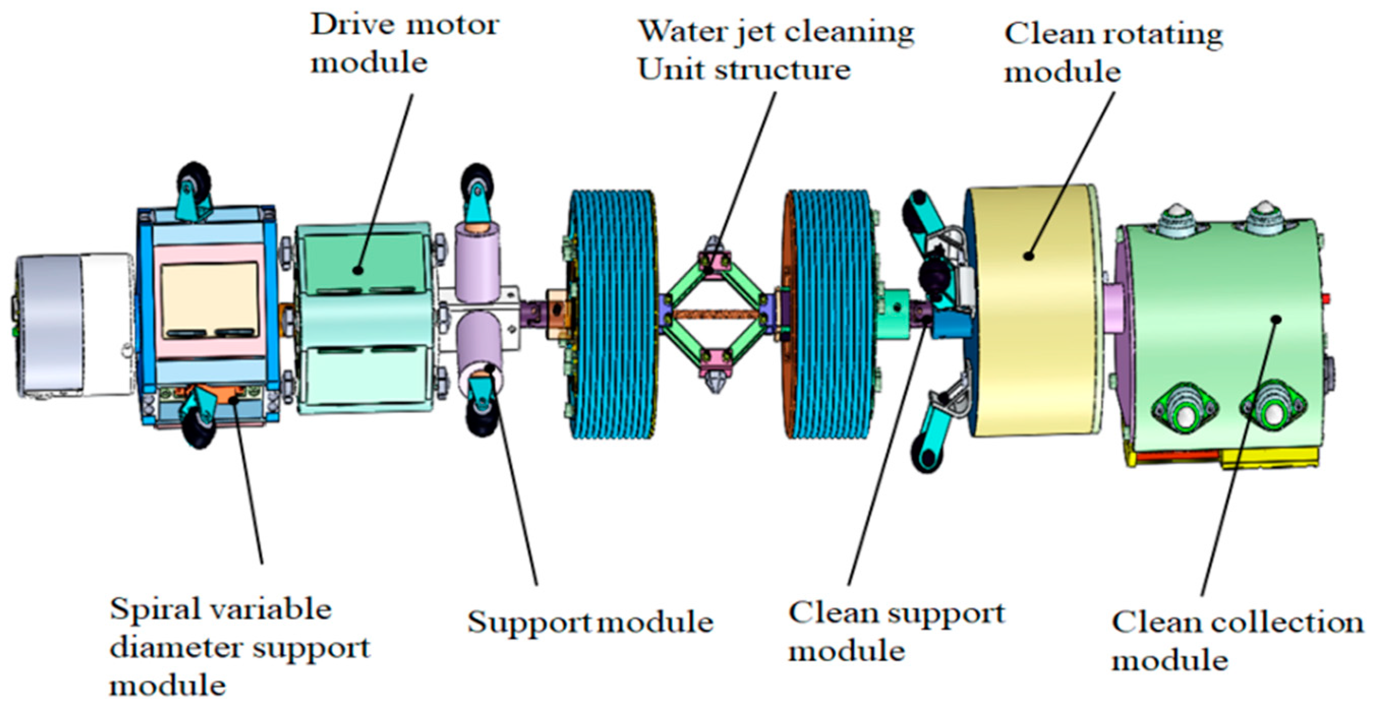
2. Pipeline Inspection and Cleaning Robot Mechanism Design

According to the operation of the assembly line, I propose the following robot performance parameters, as shown in Table 1 below
To meet these design requirements, our goal is to create a modular spiral-driven pipeline inspection and cleaning robot.

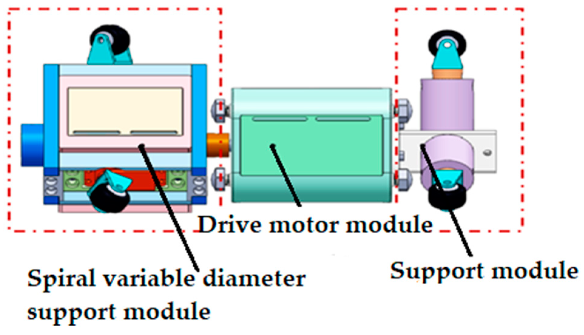
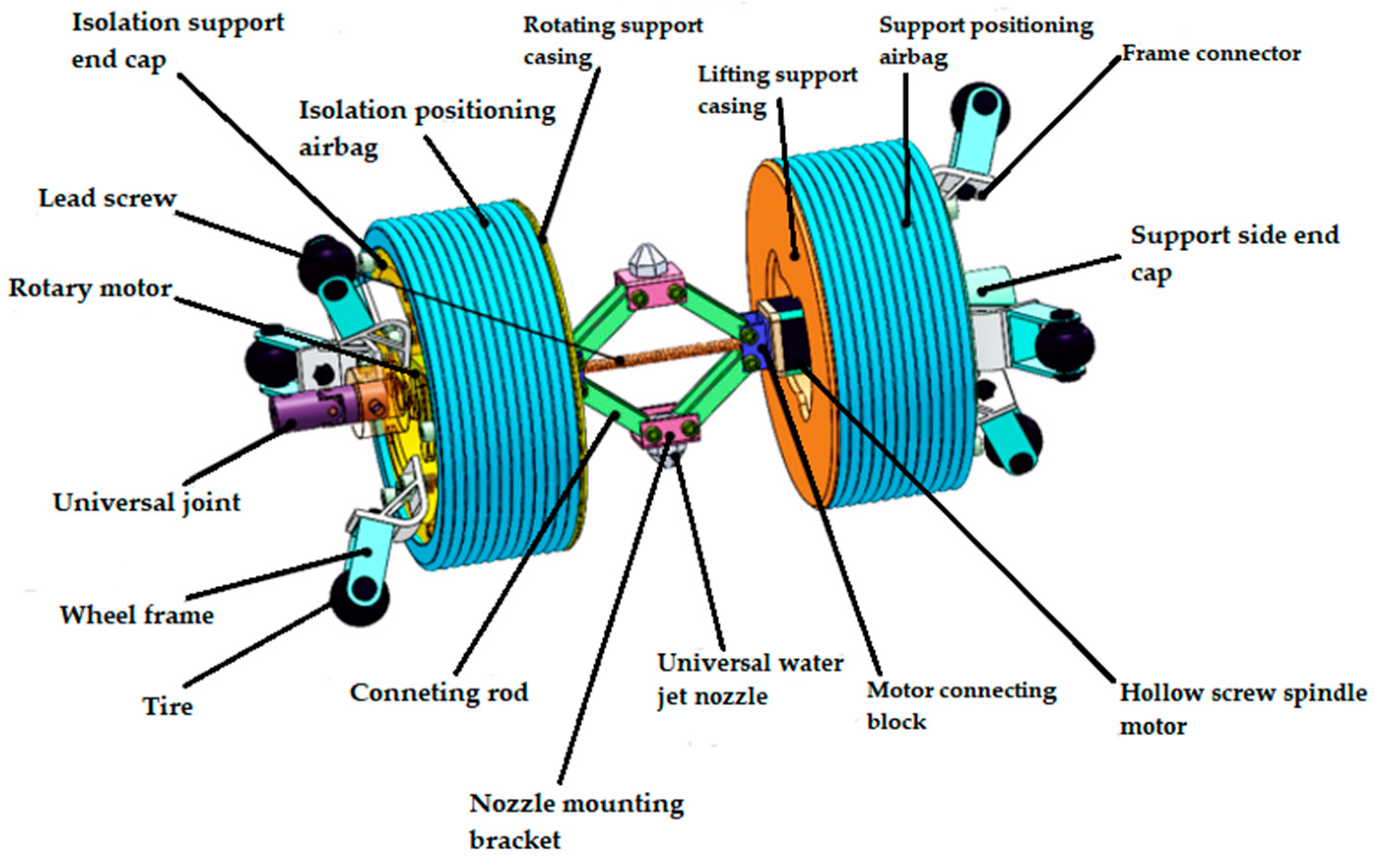
2.1. Drive Unit Structure Design

Figure 1 below illustrates the structure of the drive unit that I designed independently, including the screw bracket, motor and support module. Suitable for pipe diameters from DN180 to DN220. The drive unit is mainly powered by a combination of energy chain and battery power. The movement is spiral-shaped, and the main adaptation method involves a spring-reducer.

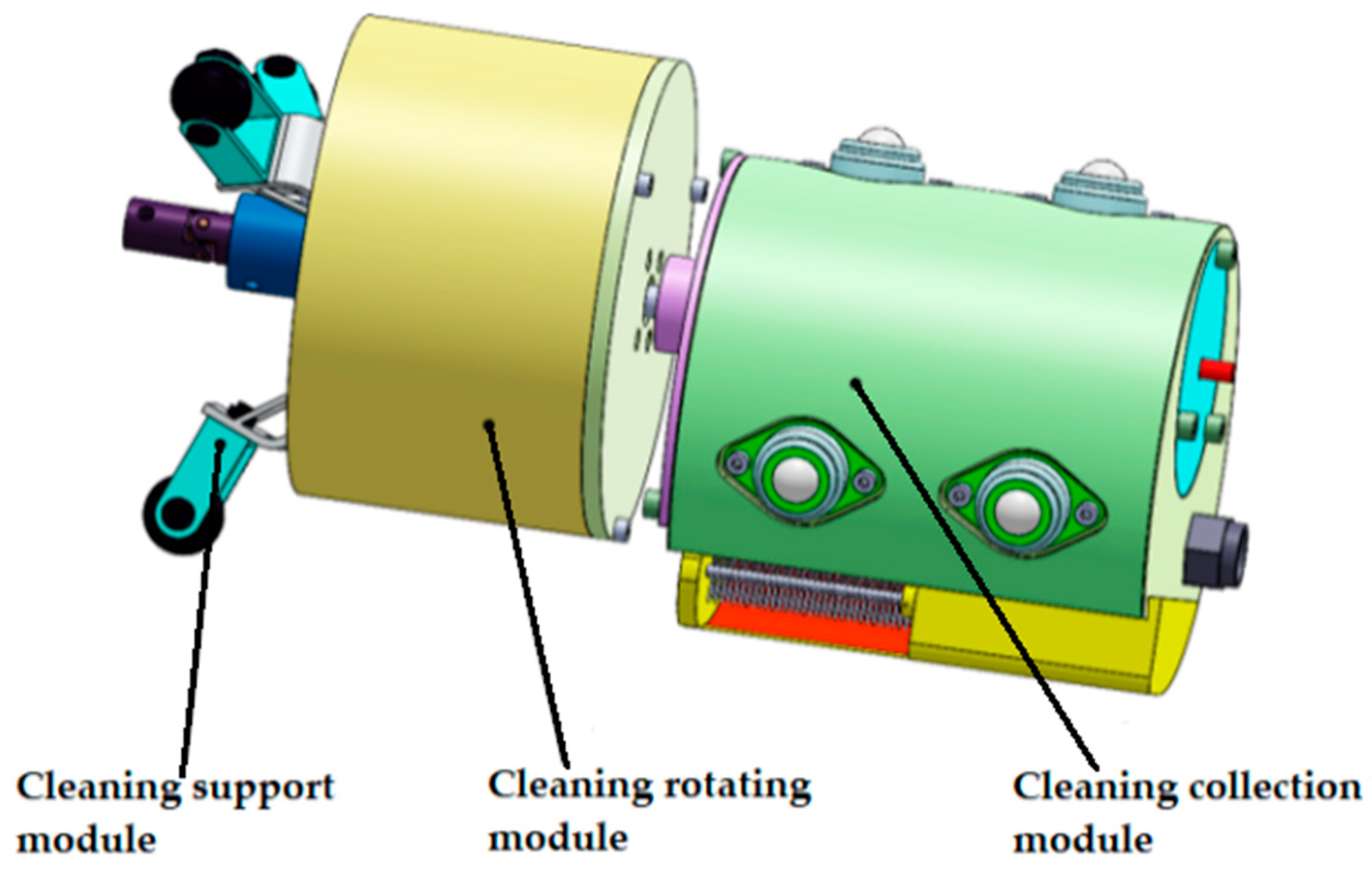
2.2. Structural Design of Water Cleaning Unit

The water jet cleaning unit is crucial for cleaning the interior of the pipeline. The structure model depicted in Figure 2 is of my own design. When the robot encounters an obstacle, the cleaning unit activates. A lifting mechanism, comprising links, nozzles, and motor connecting blocks, adjusts the nozzle height through the axial movement of the hollow spiral motor. The nozzle can rotate and adjust the jet direction within a range of 0 to 80 degrees.
When the robot approaches a pipeline section for cleaning, it halts, and the cleaning unit activates. The isolation airbag swiftly inflates, aided by the rotational support structure, ensuring uniform inflation. This isolates the robot’s drive unit from the cleaning unit, preventing interference during the cleaning jet process. The lifting-support housing, support-positioning airbag, and supporting-side end cover collectively create a stable support module for the cleaning unit. This design minimizes potential issues from cantilevered support during cleaning operations. Simultaneously, the airbag’s inflation and contact with the pipe wall enable precise and stable positioning, avoiding any adverse effects on device operation from reactive forces during jet cleaning.

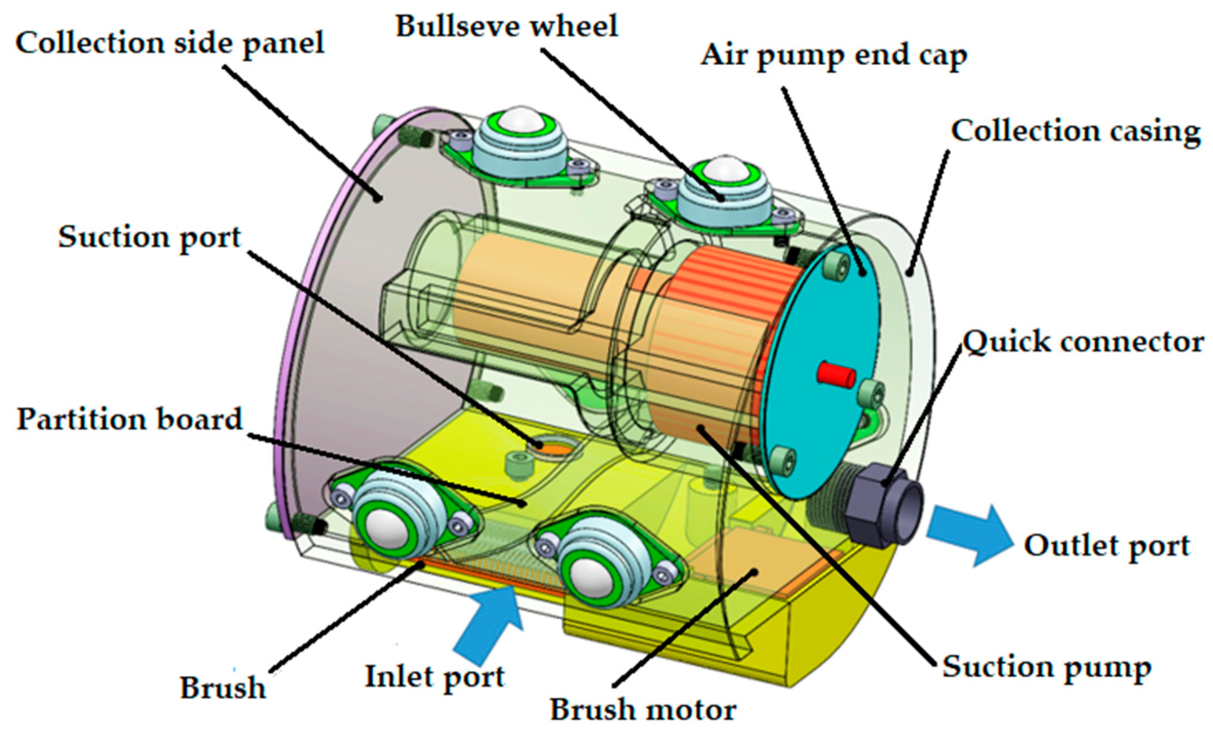
2.3. Clean Up the Collection Unit Structure Design

Figure 3 is the cleaning and collection structure model I designed, comprising three modules: cleaning support, cleaning rotation, and cleaning collection. It provides a visual representation of the structure of the cleaning and collection unit. A distinctive feature of my design is the eccentric mounting of the rotation module and the collection module.
As shown in Figure 4, the cleaning and collection module consists of ten components. Its fundamental principle involves employing sweeping and negative-pressure suction to clean and collect impurities within the pipeline.
Figure 5 displays the complete model of the robot.

3. Dipping Water Jet Cleaning Model Analysis
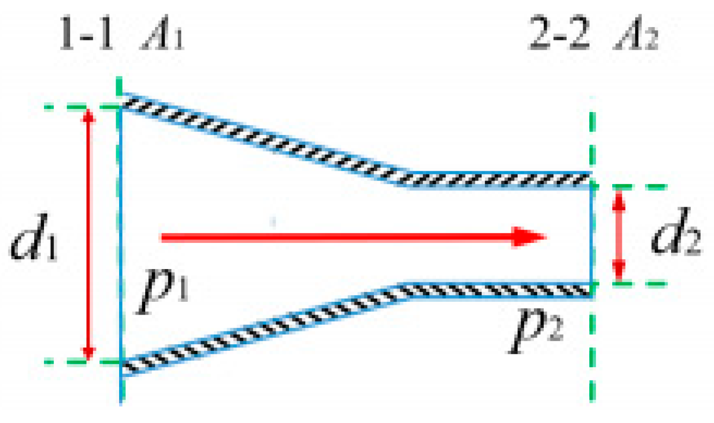
3.1. Jet Velocity

Assuming the jet nozzle model as shown in Figure 6, water flows in from section 1-1 with jet velocity v1, section diameter d1, and section pressure p1. It flows out from section 2-2 with jet velocity v2, section diameter d2, and section pressurep2. Pressure is measured in MPa, and velocity is measured in m/s. Applying the Bernoulli equation between the two sections of the nozzle, we can obtain:
p 1 ρ 1 + v 1 2 2 = p 2 ρ 2 + v 2 2 2 ρ u 1 d A 1 d t = ρ u 2 d A 2 d t u 1 d A 1 = u 2 d A 2 A 1 u 1 d A 1 = A 2 u 2 d A 2
Expressed in terms of average velocity: v 1 A 1 = v 2 A 2
Solving, simultaneously, the exit jet velocity of the nozzle is obtained as:
v = 2 p 1 p 2 ρ 1 d 2 d 1 4
The density of water, ρ , is 988 kg/m3. Substituting d 2 d 1 4 0 into the above equation, we obtain:
Therefore, the jet velocity is:
v = 2 p 1 p 2 988 = 44.72 p
Formula: v is the water jet velocity, in m/s; p is the water jet pressure, in Pa.
The jet flow rate is given by:
q = 44.72 p 1 p 2 × π d 2 4 = 11.18 π d 2 p 1 p 2
Formula: q represents the jet flow rate, measured in L/min, and d is the nozzle outlet diameter, measured in mm.
The jet power is given by:
p = 11.18 π q d 2 p 1 p 2
The water jet power is influenced by the nozzle diameter and jet pressure, as indicated by the above equation. With an increase in nozzle diameter, the jet power increases exponentially; with an increase in jet pressure, the jet power increases with a square root relation. Consequently, the change in nozzle diameter has a more significant impact on jet power compared to jet pressure. This provides a theoretical basis for setting simulation parameters in subsequent jet simulations.

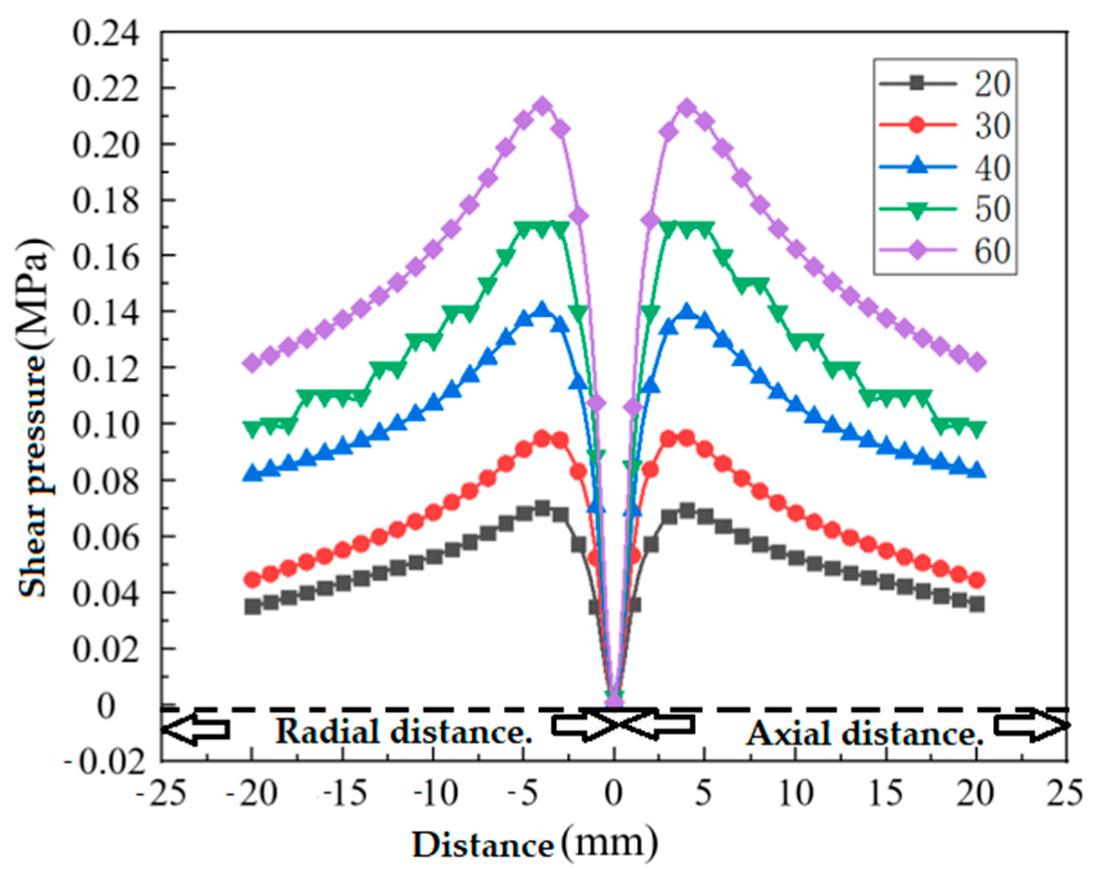
3.2. Water Jet Shear Force

The water jet has the maximum impact force at its center, with shear force increasing outward and eventually decreasing to zero. Optimal cleaning occurs where shear force is maximum, and at the jet center, shear force is zero, resulting in minimal cleaning volume. The equation expressing wall shear force is:
τ w x ρ K = F τ K v r x m
Formula: τ w represents the wall shear force; m is a constant; x is the distance to the target surface; r is the distance from any point on the wall to the center; F τ K v is a function of the initial jet Reynolds number.
Figure 7 depicts an immersion-type water jet cleaning schematic. Line AB represents the pipe wall’s axial direction. A jet with velocity V1 and density ρ horizontally enters the pipe wall. After colliding, it exits on both sides (A and B) at speeds V2 and V3, with atmospheric pressure (P2 = P3 = Pa). The angle with the AB pipe wall is θ. The jet-AB pipe wall intersection serves as the circle center, with the vertical AB pipe wall as the y-axis. The equation A1 = A2 + A3 holds, regardless of jet compression.
Its energy equation is:
A n V V 2 2 + p ρ + U ρ d A = 0
Formula: U units of mass potential energy; V is the jet velocity.
From the continuity equation, we obtain:
A ρ n V d A = 𝜕 𝜕 t A ρ d τ
The jet pressure along the wall can be expressed as:
p = p a + ( p p a )
The resultant force F of the target surface is:
A p a d A = A a + A b + A 1 + A 2 + A 3 n p d A = A a + A b + A 1 + A 2 + A 3 n p a d A A b n [ p a + ( p p a ) ] d A = A a + A b + A 1 + A 2 + A 3 n p a d A A b n ( p p a ) d A = j A b ( p p a ) d A
F = F f = j A b ( p p a ) d A
From zero mass force:
A ρ V V n d A = A 1 ρ V 1 cos θ V 1 i d A + A 1 ρ V 1 sin θ V 1 j d A + A 2 ρ V 2 i V 2 j d A + A 3 ρ V 3 i V 3 d A = i ρ V 1 2 A 1 cos θ + ρ V 1 2 A 1 sin θ j + A 2 ρ V 2 2 i + i ρ A 3 V 3 2 = i ρ V 1 2 A 2 A 1 cos θ A 3 + ρ V 1 2 A 1 sin θ j
Since the assumption is a constant flow, there are:
τ 𝜕 𝜕 t ( p V ) d τ = 0
Substitute the above equations into the momentum equation:
τ ρ f d τ + A p n d A A ρ V n V d A = 𝜕 𝜕 t τ ρ V d τ = 0
This produces:
F = ρ V 1 2 ( A 2 A 3 ) τ ρ f d τ + A p n d A A ρ V n V d A = 𝜕 𝜕 t τ ρ V d τ = 0
F = i ρ V 1 2 A 2 A 1 cos θ A 3 + ρ V 1 2 A 1 sin θ j
At the same time, because it is an ideal fluid, the force of the jet on the pipe wall can only be perpendicular to it.
F f = ρ V 1 2 A 1 sin θ j
Due to the small diameter of the nozzle, when the jet hits the pipe wall, its force area is roughly equal to the jet section A1, so the force per unit area of dirt is:
σ f = F f A 1 = ρ V 1 sin θ
where ρ is the density of the fluid; V 1 is the velocity of the jet outlet; θ is the angle between the jet axis and the tube wall.
High-pressure water jet cleaning effectively removes dirt by applying water pressure exceeding the dirt’s ultimate pressure. This pressure breaks the dirt, while the jet’s shear stress gradually washes away and removes the dirt from the surface.
From the above results, it can be seen that the stress σ f of the high-pressure water jet on dirt is related to factors, such as fluid density, jet outlet velocity, jet axis, and pipe wall angle.
(1)
Appropriately increasing the flow rate and angle can improve the cleaning performance.
(2)
The speed of the nozzle is proportional to the square root of the nozzle pressure, so appropriately increasing the nozzle pressure can improve the cleaning effect.

4. Simulation Analysis of Water Jet Cleaning of Robot Cleaning Device

To study the impact of various factors on water jet cleaning, a numerical simulation model was designed using Workbench software. We created nozzle and pipe wall models in SolidWorks, imported them into Fluent for fluid analysis, set the model to fluid mode, employed modules for grid division with a cell size of 0.2, defined boundary grids at the model’s edges, checked the 1,805,602 grids for negative volumes, and specified the nozzle inlet as “inlet”, the surrounding fluid walls as “outlet”, and the pipe wall as “wall”. As shown in Figure 8.
In FLUENT, the 3D model was configured by adjusting parameters. The accuracy in settings was crucial due to the two-phase interaction between the jet and the wall. After determining the core count, the units were changed to millimeters in the main interface, and dimensions were checked. Gravity was set to 9.8 m/s2. Initially, we chose the multiphase flow simulation model, specifically the Euler Model suitable for high-pressure water jet cleaning. This model considers two phases: water with a density of 998.2 kg/m3 and a viscosity of 0.001 kg/(m·s) and air with a density of 31.225 kg/m3, without considering the impact of slip velocity.
Set the control equation of the device as:
𝜕 𝜕 t ( ρ m ) + ρ m V m = m
Formula: V m is the average velocity of the mass, and ρ m is the density of the mix.
The momentum equation for a mixed model is expressed as:
𝜕 𝜕 t ( ρ m V m ) + ρ m V m = P + μ m V m + μ m V m T + ρ m g + F + k = 1 n α k ρ k V d r , k
In the above equation, n is the number of phases of 2; F is the volumetric force; ρ m is mixed viscosity.
Thus, the water jet spraying state is turbulent. The sStandard k ε model is used in this case. The turbulent kinetic energy k and dissipation rate ε equations for the sStandard k ε model are given in the following form:
ρ d k d t = 𝜕 𝜕 x i μ + μ t δ k 𝜕 k 𝜕 x i + G k + G b ρ ε Y M
ρ d k d t = 𝜕 𝜕 x i μ + μ t δ k 𝜕 k 𝜕 x i + G 1 ε ε k + ( G k + G 3 ε G b ) G 2 ε ρ ε 2 k
Formula: G k is generated by turbulent kinetic energy caused by the average velocity gradient; G b is the turbulent energy generated due to the influence of buoyancy; Y M is the effect of compressible turbulent pulsation expansion on the total dissipation rate.
The formula for the turbulent viscosity coefficient is:
μ t = ρ C μ k 2 ε
In the equation above, C μ is the coefficient of viscous diffusion, C 1 ε = 1.44, C 2 ε = 1.92; k is the turbulent kinetic energy, and the turbulent Prandtl number for δ k is 1.0; ε is the dissipation rate, and the turbulent Prandtl number for δ ε is 1.3.
The nozzle inlet pressure is set to 30 MPa; the outlet pressure is set to 0 MPa. The initial water phase fraction is set to 1. Local initialization is performed at the jet inlet. The iteration steps are set to 1000, and the residual is set to e−6.

4.1. The Impact of Jet Pressure on Cleaning Efficiency

We assess cleaning efficiency by altering jet pressures, maintaining a constant nozzle diameter of 2 mm and an outlet straight section length of 3 mm. The target distance remains fixed at 25 mm, with an incident angle set at 0°. We progressively vary jet pressures from 20 MPa to 60 MPa. In these conditions, we analyze the impact force on the target surface and the magnitude of the jet shear force to evaluate the effect of water jet pressure on cleaning efficiency.
Figure 9 depicts the impact force distribution on the target surface at water jet pressures of 20 MPa, 30 MPa, 40 MPa, 50 MPa, and 60 MPa.
Observing the impact force distribution on the target surface, as depicted in Figure 9 for water jet pressures of 20 MPa, 30 MPa, 40 MPa, 50 MPa, and 60 MPa, it becomes evident that with higher jet pressure, the maximum impact force on the target surface steadily rises. This signifies an enhanced capacity to dislodge contaminants and a more pronounced cleaning effect.
Figure 10 presents the jet shear force distribution at various water jet pressures (20 MPa, 30 MPa, 40 MPa, 50 MPa, and 60 MPa). With increasing pressure, the maximum shear force gradually rises, indicating improved removal of contaminants and more efficient cleaning. Since jet cleaning primarily targets non-consolidated materials within the pipe, a jet pressure of 20 MPa suffices for effective cleaning. Nevertheless, to strike a balance between energy efficiency and thorough cleaning, we opt for a jet pressure of 30 MPa. In summary, modest increases in jet pressure enhance cleaning effectiveness while minimizing the potential for damage to the pipe wall.

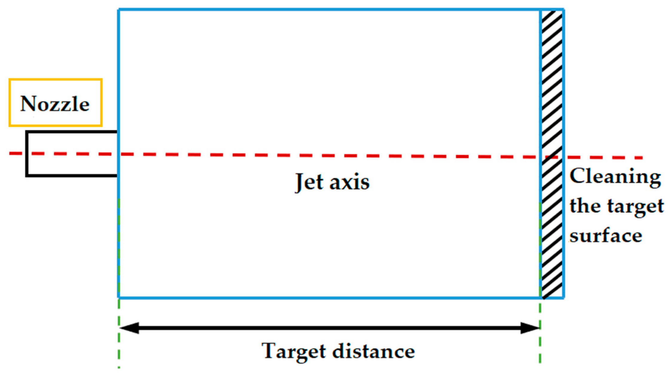
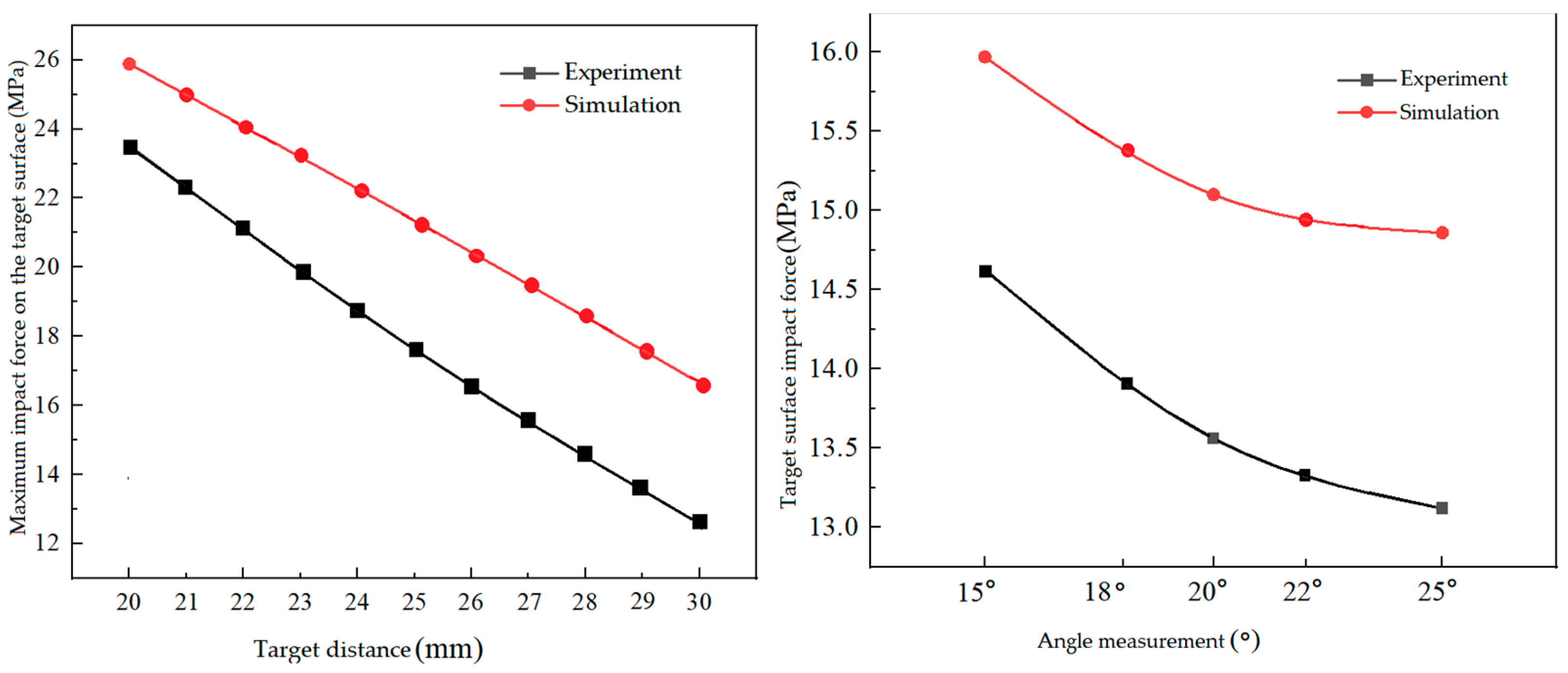
4.2. Influence of Jet Target Distance on Cleaning Effect

Figure 11 illustrates a cleaning model for the target surface with a 2 mm nozzle outlet diameter and a 3 mm straight length from the nozzle outlet. The jet angle is set at 0 degrees, and the inlet pressure remains constant at 30 MPa. Through the variation in the target surface distance, we analyze its impact on jet impact force, shear force, and the area of effective cleaning. The optimal cleaning condition within the specified parameters is identified by optimizing the target surface distance.
In this simulation, the adjustment of the jet target distance is primarily achieved through the lifting mechanism of the jet cleaning unit, with a maximum height of approximately 120 mm. As a result, our focus will be on investigating the jet cleaning process at distances of 10 mm, 20 mm, 30 mm, and 40 mm.
Figure 12 illustrates the pressure variation trend at these target distances. The data reveal that as the flow velocity along the jet axis decreases, the pressure on the target surface gradually increases. Furthermore, this pressure increase intensifies with decreasing velocity, indicating the conversion of water jet kinetic energy into impact energy on the target surface.
Figure 12 illustrates that as the target distance increases, the maximum impact force on the target surface gradually decreases. At a target distance of 40 mm, this force falls below 13.7 MPa, which is approximately 45% of the initial pressure, indicating a significant pressure drop. Consequently, this case will not be further considered. At a target distance of 30 mm, the maximum impact force reaches nearly 16.7 MPa, accounting for about 55.7% of the initial pressure. Similarly, at a target distance of 20 mm, the force reaches nearly 25.8 MPa, representing approximately 86% of the initial pressure.
Figure 13 illustrates the impact pressure distribution on the target surface, with the highest pressure occurring at the nozzle center. As the distance from the center increases, the impact pressure gradually decreases. The curve of impact pressure on the target surface peaks at the jet center and gradually diminishes on both sides.
Referring to Figure 13, for dirt removal requiring pressures within the 0–12.5 MPa range, a 30 mm target distance is ideal, providing a larger cleaning area and efficient dirt removal. For pressures exceeding 12.5 MPa, a 10 mm target distance is preferable due to higher water jet pressure, lower pressure loss, and a larger jetting area compared to 30 mm. If cleaning pressure exceeds 17 MPa at a 30 mm target distance, the maximum water jet pressure on the pipe wall is 16.7 MPa, insufficient for effective dirt removal.
Referring to Figure 14, it illustrates the radial shear force distribution on the target surface. The maximum shear force coincides with the jet center, where the impact force reaches its peak. Wall shear stress is minimal at the jet center and increases with the distance from it. Along the jet center direction, there are two peaks, signifying the location of maximum shear stress and the most efficient cleaning area. Shear force decreases rapidly towards the jet center and gradually as you move away from the nozzle center, forming a symmetric “M” shape at different target distances.
Figure 15 illustrates the change in effective cleaning width on the target surface at various target distances. Irrespective of the dirt cleaning pressures, the effective cleaning width initially decreases and then increases as the nozzle outlet distance increases. At a dirt cleaning pressure of 10 MPa, the cleaning width measures approximately 5.2 mm. With increasing cleaning pressure, the effective cleaning width steadily decreases while maintaining the consistent trend of an initial increase followed by a decrease.
In summary, reducing the target distance can elevate the pressure exerted on the pipe wall, potentially causing more surface damage. Therefore, it is crucial to choose the right pressure levels for cleaning various materials and opt for suitable target distances to enhance cleaning efficiency. Employing a single high-pressure water jet for cleaning allows for a larger cleaning area, thereby improving effectiveness. To strike a balance between high-pressure flushing and flushing range, it is advisable to maintain a target distance of approximately 25 mm, which is around 12–13-times the nozzle outlet diameter.

4.3. The Effect of Inclination Angle on Cleaning Effectiveness

When the nozzle sprays at an angle, the cleaning effect varies on two sides: the side aligned with the jet direction receives intense cleaning, while the opposite side experiences lower intensity. Nevertheless, when the jet strikes the surface at an inclined angle, both the impact force and velocity on the target surface are modified. Figure 16 illustrates the cleaning model for a target surface with an inclined angle.
While studying the variations in impact force and velocity on the target surface, we analyze different jet incidence angles, considering parameters, such as a 2 mm nozzle outlet diameter, a 5 mm straight segment length, and a 25 mm target surface distance.
Figure 17 illustrates pressure curves at varying incidence angles, showing a gradual decrease in impact pressure on the target surface with increasing incidence angle. Velocity and pressure cloud maps are presented for nozzle tilt angles of 5°, 10°, 15°, 20°, 25°, and 30°, all at a target surface distance of 25 mm.
At a 5° tilt angle, the target surface pressure is approximately 19.38 MPa, indicating a 9.3% pressure reduction compared to a vertical jet. The pressure decreases to around 17.89 MPa at a 10° tilt angle, resulting in a 16.2% reduction. A 15° tilt angle results in a pressure of about 15.97 MPa, reflecting a 25.2% decrease. For a 20° tilt angle, the pressure is 15.1 MPa, representing a 29.3% reduction. At a 25° tilt angle, the pressure is roughly 14.86 MPa, signifying a significant 30.4% pressure drop. The pressure decreases to around 13.73 MPa at a 30° tilt angle, resulting in a 35.7% reduction compared to a vertical jet.
The maximum impact force on the target surface is achieved at a 25° incidence angle, corresponding to a pressure of 14.86 MPa.
In summary, it is evident from the cloud maps that the incidence angle has a significantly lesser effect on the jet’s impact force when compared to the target distance.
The analysis suggests that to reduce the jet impact force to 15 MPa, it is recommended to use a nozzle tilt angle of around 20°. Adjusting the nozzle tilt angle during jet wall cleaning can improve the efficiency. Figure 18 displays the maximum shear force curves at different incidence angles.
In Figure 18, the maximum shear force on the target surface initially rises, then decreases with increasing incidence angle. It remains relatively stable between 15° and 20°, peaking at 25°. A very small angle yields minimal shear force and a narrow shear zone, while an overly large angle causes significant energy loss in the jet. With increased angle, the maximum shear action zone expands. The findings suggest that at an incidence angle of 15–20°, the maximum shear force on the wall surface is around 0.11 MPa.
Referring to Figure 19, when the jet enters at a specific angle, the impact force curve on the target surface becomes asymmetrical and shifts in the direction of the jet. This leads to a larger cleaning area along the jet direction, as opposed to the opposite direction.
Figure 20 shows the variation in the effective cleaning area on the target surface at different jet angles. Based on the analysis from the previous figure, it is evident that the effective cleaning width of the target surface remains fairly consistent when the incidence angle is between 0° and 15°. However, as the incidence angle gradually increases, the effective cleaning width decreases. At a cleaning pressure of 15 MPa, the cleaning width becomes zero for incidence angles between 20° and 30°. Therefore, to ensure a larger effective cleaning area, it is advisable to maintain an incidence angle of approximately 15°.
In summary, a 15° incidence angle is recommended for achieving the desired jet impact force to dislodge dirt, maintaining ample wall shear force and increasing the effective cleaning width on the surface, thus enhancing cleaning speed. This angle ensures optimal jet cleaning performance.

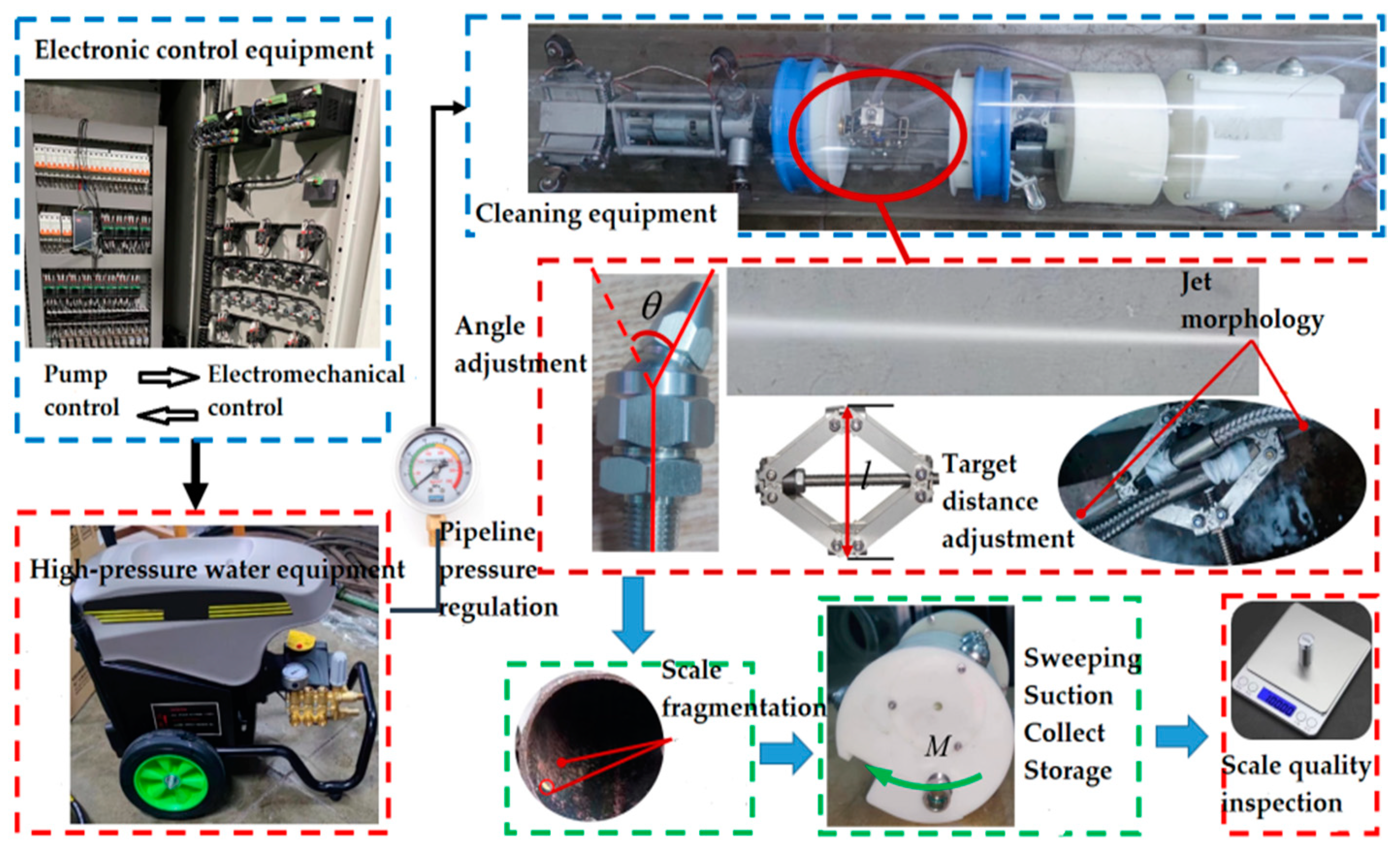
5. Experimental Study on Characteristics of Robot Water Jet Cleaning

5.1. Establishment of the Experimental Platform for Pipeline Robot Water Jet Cleaning

Water jet cleaning effectively removes impurities from pipelines. An experimental platform will be set up to investigate the impact of parameters on cleaning performance. This platform comprises a high-pressure water pump, a cleaning robot section, and electrical control equipment (see Figure 21).
Currently, there is no standardized method for assessing scale removal quality in pipeline cleaning. Due to pipeline constraints, measuring factors like cleaned area and effective cleaning width post-water jet cleaning is challenging, making it difficult to evaluate experimental results. To mitigate the impact of subpar pipeline conditions, a 1 kg blend of sand and cement was employed to mimic internal debris. Although this mixture does not fully replicate real-world debris accumulation, varying proportions of the blend can tailor the necessary pressure for effective dirt removal, creating a simulated cleaning environment within the pipeline.

5.2. Cleaning Experiment Process

(1)
Follow the design to assemble the experimental setup. Connect the drive unit to the water jet cleaning unit and link the high-pressure water pump to the cleaning unit. Inspect pipeline seals to prevent high-pressure water hose detachment during cleaning.
(2)
Place the apparatus within the pipe and refine the robot’s movement for water jet cleaning. Inflate the isolation airbag to prevent interference. Adjust the water jet’s rotation speed and occasionally change the motor rotation direction to prevent hose tangling. After completing one full cleaning cycle, deflate the airbag, and move the apparatus forward by one width for the next cycle. Continue this process until all dirt is thoroughly removed.
(3)
Subsequently, dry the pipes meeting the standards and measure the quality difference before and after cleaning.
(4)
Lastly, the experimental pipes undergo multiple cleaning cycles to ensure thorough dirt removal. Additionally, an anti-rust treatment is applied to prevent corrosion.

5.3. Experimental Analysis

5.3.1. Experimental and Simulation Analysis

The impact force is a crucial factor in determining the effectiveness of jet cleaning, making it highly valuable for jet cleaning applications. Utilizing the established experimental platform and cleaning process description, the following experiments were conducted. Under a pressure of 30 MPa, the impact forces at different target distances from 20 to 30 mm were measured using a pressure sensor with a jet angle of 0°. This resulted in experimental and simulation comparison charts of the impact force on the target surface at various distances. With the target distance fixed at 25 mm, the jet angle was adjusted to 15°~25° to obtain the corresponding impact force values on the target surface. The experimental and simulation comparison chart of the impact force on the target surface at 30 MPa is shown in Figure 22.
Figure 22 illustrates that with increasing target distance and jet angle, the impact force on the target surface decreases gradually. Both the experimental and simulated values exhibit a similar trend, but the gap between them widens with greater target distances and angles. This difference can be attributed to factors like pressure variations and experimental conditions. Based on these results, it can be concluded that the target distance has a more substantial impact compared to the jet angle.

5.3.2. Experimental Fluid Resistance

When the device performs jet cleaning operations inside the pipeline, the fluid originally accumulated at the bottom of the pipeline, and the liquid generated by the jet will exert a certain resistance to the movement of the device, known as fluid resistance. The formula for calculating fluid resistance F is as follows:
F j = 1 2 c A P w v r + v w 2
Formula: c is the fluid resistance coefficient; A represents the effective cross-sectional area; P w is the density of the medium; v r is the operating speed of the device; v w is the velocity of the medium.
We Assume a liquid flow velocity of approximately 0.5 m/s inside the pipe, a robot movement speed of 0.05 m/s, operating in a DN200 steel pipe, with a fluid viscosity of 1.005 × 10⁻³ Pa, fluid resistance coefficient of 1.2, and an effective cross-sectional area of 0.01 m2. In this scenario, the fluid resistance F j is 3.1 N.
We can adjust the motor and drive wheels to regulate the robot’s speed. Increasing the motor speed and wheel steering angle enhances operational speed. Maintaining the same wheel steering angle during straight pipe operations ensures smooth running.

5.3.3. Experimental Analysis of Pipeline Jet Cleaning

The jet cleaning experiment investigates various parameters. Table 2 presents the experimental results for jet cleaning, conducted at jet pressures of 20 MPa and 30 MPa, target distances of 20 mm, 25 mm, and 30 mm, and incident angles of 15° and 20°. Each experiment is conducted three times, and the average value is computed.
The analysis suggests that jet pressure significantly impacts cleaning effectiveness. The results consistently demonstrated better cleaning performance at 30 MPa compared to 20 MPa. Furthermore, at 30 MPa, cleaning effectiveness was superior at a target distance of 25 mm compared to 20 mm. The experimental findings indicate that jet angle has the least influence on the outcome. A jet angle of 15° effectively removes the dirt layer, but cleaning effectiveness diminishes when the angle is increased to 20°. Considering overall cleaning performance, it is recommended to use a jet pressure of 30 MPa, a target distance of 25 mm, and a jet angle of 15° for pipe cleaning operations.

6. Conclusions

(1)
We propose a mechanical and water jet cleaning method to efficiently remove pipeline impurities without causing damage to the pipes. The device employs scraping, brushing, and suction to collect impurities within the pipeline.
(2)
Higher jet pressure enhances shearing forces and improves cleaning efficiency. Applying greater pressure at a target distance of around 25 mm (12–13-times the nozzle exit diameter) yields superior cleaning results.
(3)
Adjusting the nozzle angle affects impact and shearing forces during cleaning. A 15° incident angle achieves optimal cleaning with a strong shearing force of approximately 0.11 MPa. Properly adjusting parameters like target distance and incident angle significantly enhances jet cleaning efficiency.
(4)
Using an in-pipe cleaning platform, the optimal cleaning conditions for the robot were determined: 25 mm target distance and 15° incident angle. This research on the spiral-driven robot provides a theoretical basis for pipeline cleaning, inspection, and maintenance.
By establishing a model for a spiral-driven pipeline inspection and cleaning robot, we successfully completed the prototype fabrication and the setup of a testing platform for the robot. The results indicate that the optimal cleaning condition for the robot within the pipeline is achieved at a jet pressure of approximately 30 MPa, a target distance of 25 mm, and a jet incident angle of 15°.

Author Contributions

Equipment design and manufacturing process, H.Y.; prototype processing, manufacturing, and methodology, H.N. and H.Y.; control systems and software development, H.N. and Q.C.; writing and review, H.Y. and H.N.; simulation analysis, H.N. and B.H.; experimental support, P.Z. and B.H. All authors have read and agreed to the published version of the manuscript.

Funding

This paper was completed under the Shanxi Provincial Basic Research Program Project “Research on the Kinematic Characteristics of the Driving Mechanism for Leakage and Blockage Repair in Multi-point Dispersion Section of Pipelines” (20210302123038), the Shanxi Provincial Science and Technology Cooperation and Exchange Project “Intelligent Equipment Technology for Pipeline Defect Detection and Emergency Prevention and Control of Hazardous Sources” (202104041101001), and the Shanxi Provincial Scholarship Council funded research project “Research on Leakage and Plugging Repair Technology of Screw-driven Pipeline Robot” (2020-110). At the same time, it has also received funding from the Science and Technology Project of North University of China: the Science and Technology Project of North University of China “Research on Circular Welding Robot Technology for Pipeline Internal Welding” (20221817).

Data Availability Statement

Data are contained within the article.

Acknowledgments

This research was generously supported by the following organizations, to which we express our sincere gratitude: Shanxi Provincial Key Laboratory of Advanced Manufacturing, North University of China; Taiyuan University of Technology National and Local Joint Engineering Laboratory of Mine Fluid Control; Shanxi Datong University Coal Mine Electromechanical Technology Institute; Shanxi Coal Import and Export Group Science and Technology Research Institute Co., Ltd.; and Shanxi Honganxiang Science and Technology Co., Ltd. The authors would like to express their gratitude for the support of this study. Moreover, the authors sincerely thank Wu Wenge of North University of China for his critical discussion and Dahua Xie of Silicon Valley USA for linguistic assistance during the preparation of this manuscript.

Conflicts of Interest

The authors declare no conflict of interest.

References

  1. Wang, W.; Zhao, S. Research status and prospects of pipeline robots. Ordnance Ind. Autom. 2019, 38, 24–30. [Google Scholar]
  2. Liu, Y. Structure and control system design of variable diameter pipeline robot. Agric. Equip. Veh. Eng. 2022, 60, 114–116. [Google Scholar]
  3. Lu, Y.J. Design and research on modular adaptive pipeline robot mechanism. Gansu Sci. Technol. 2021, 37, 10–14+18. [Google Scholar]
  4. Li, Z.Q.; Li, W.G.; Feng, Z.C.; Wang, L.L.; Yan, W.G.; Guo, S.J. Structure and passability analysis of pipeline robots. Mech. Transm. 2021, 45, 146–152. [Google Scholar]
  5. Zhang, Y.J. Overview of pipeline robots. Equip. Manuf. Technol. 2021, 6, 114–117+138. [Google Scholar]
  6. Xiao, C.; Tu, F.Q.; Xing, Y.; Lei, D. Optimization design of variable diameter mechanism for urban drainage pipeline cleaning robot. Manuf. Autom. 2021, 43, 89–92. [Google Scholar]
  7. Rashid, M.Z.A.; Yakub, F.; Zaki, S.A.; Ali, M.S.M.; Mamat, N.M.; Putra, S.M.S.; Roslan, S.A.; Shah, H.N.M.; Aras, M.S.M.; Arshad, M.R. Reconfigurable multi-legs robot for pipe inspection: Design and gait movement. Indian J. Geo-Mar. Sci. 2019, 48, 1132–1144. [Google Scholar]
  8. Yeh, C.-Y.; Chen, C.-Y.; Juang, J.-Y. Soft hopping and crawling robot for in-pipe traveling. Extreme Mech. Lett. 2020, 39, 100854. [Google Scholar] [CrossRef]
  9. Wu, T.-T.; Zhao, H.; Gao, B.-X.; Meng, F.-B. Structural optimization strategy of pipe isolation tool by dynamic plugging process analysis. Pet. Sci. 2021, 18, 1829–1839. [Google Scholar] [CrossRef]
  10. Zhang, Y.; Wang, N.; Zhao, W.C.; Lu, D.Y. Design and testing of peristaltic soft pipe robot. Food Mach. 2020, 36, 82–86. [Google Scholar]
  11. Yang, C.X.; Li, J.J.; Xu, X.D. Design and simulation research on traction mechanism of supported oil and gas pipeline robot. China Equip. Eng. 2020, 07, 83–85. [Google Scholar]
  12. Kakogawa, A.; Ma, S. Design of a multilink-articulated wheeled pipeline inspection robot using only passive elastic joints. Adv. Robot. 2018, 32, 37–50. [Google Scholar] [CrossRef]
  13. Gao, Y.B.; Xiang, X.; Guo, X.Y.; Han, P.Z. Research on characteristics and mechanism of coal and rock drilling by water jet impact. J. Vib. Shock 2022, 41, 51–59+85. [Google Scholar]
  14. Wan, L.; Qian, Y.N.; Tu, Y.X.; Du, H.; Wu, S.J.; Li, D. Prediction of profile characteristics in single-pass milling of titanium alloy with abrasive water jet. J. Mech. Eng. 2022, 58, 296–305. [Google Scholar]
  15. Wu, W.; Tang, Y.; Yuan, S.; Li, M.J. Influence of pipeline symmetry on flow field of rear-mix abrasive water jet nozzle. Fluid Mach. 2022, 50, 97–104. [Google Scholar]
  16. Liu, Y.; Zhou, J.; Wang, P.; Kong, X.; Zhao, Y.; Chen, H.; Zhou, Y. Design and Antiblast Analysis of Mechanical Plugging Devices in Coastal Defense Engineering. J. Coast. Res. 2020, 111, 101–107. [Google Scholar] [CrossRef]
  17. Zhang, S.; Dubljevic, S. Trajectory determination for pipelines using an inspection robot and pipeline features. Metrol. Meas. Syst. 2021, 28, 439–453. [Google Scholar] [CrossRef]
  18. Yaqub, S.; Ali, A.; Usman, M.; Zuhaib, K.M.; Khan, A.M.; An, B.; Moon, H.; Lee, J.Y.; Han, C. A Spiral Curve Gait Design for a Modular Snake Robot Moving on a Pipe. Int. J. Control Autom. Syst. 2019, 10, 2565–2573. [Google Scholar] [CrossRef]
  19. Zhu, Y.; He, X.; Liu, Q.; Guo, W. Semiclosed-loop motion control with robust weld bead tracking for a spiral seam weld beads grinding robot. Robot. Comput. Manuf. 2022, 73, 102254. [Google Scholar] [CrossRef]
  20. Mizukami, M.; Harada, D.; Hanajima, N.; Fujihira, Y. Movement control for an omnidirectional mobile mechanism for pipe-inspect ion robot in small diameter pipes. Seimitsu Kogaku Kaishi/J. Jpn. Soc. Precis. Eng. 2020, 86, 898–903. [Google Scholar] [CrossRef]
  21. Chi, M.; Zhang, J.; Liu, R.; Wang, Y.; Nie, G.; Qian, X. Coupled steering control of a low torsional torque capsule robot in the intestine. Mechatronics 2021, 77, 102596. [Google Scholar] [CrossRef]
  22. Bai, J.; Wu, J.; Chi, M.; Fan, Z.; Du, Z. Self-starting Characteristics of Magnetic Controlled Spiral Capsule Robots. J. Eng. Sci. Technol. Rev. 2019, 12, 43–52. [Google Scholar] [CrossRef]
  23. Ito, F.; Takaya, K.; Kamata, M.; Okui, M.; Yamada, Y.; Nakamura, T. In-Pipe Inspection Robot Capable of Actively Exerting Propulsive and Tractive Forces With Linear Antagonistic Mechanism. IEEE Access 2021, 9, 131245–131259. [Google Scholar] [CrossRef]
  24. Kazeminasab, S.; Sadeghi, N.; Janfaza, V.; Razavi, M.; Ziyadidegan, S.; Banks, M.K. Localization, Mapping, Navigation, and Inspection Methods in In-Pipe Robots: A Review. IEEE Access 2021, 9, 162035–162058. [Google Scholar] [CrossRef]
  25. Li, T.; Liu, K.; Liu, H.; Cui, X.; Li, B.; Wang, Y. Rapid design of a screw drive in-pipe robot based on parameterized simulation technology. Simul. Trans. Soc. Model. Simul. Int. 2019, 95, 659–670. [Google Scholar] [CrossRef]
  26. Yang, W. Mechanism Design and Pipeline Traversability Study of Active Helical Driven Pipeline Robot; Harbin Institute of Technology: Harbin, China, 2018. [Google Scholar]
  27. Cao, J.S.; Xu, B.D.; Lu, J.; Liu, Q.; Zhang, Y.; Huang, Z.M. Crawl-type sewage pipeline dredging robot. Mach. Tool Hydraul. 2014, 42, 50–53. [Google Scholar]
  28. Yan, H.; Li, J.; Kou, Z.; Liu, Y.; Li, P.; Wang, L. Research on the Traction and Obstacle-Surmounting Performance of an Adaptive Pipeline-Plugging Robot. Stroj. Vestn. J. Mech. Eng. 2022, 68, 14–26. [Google Scholar] [CrossRef]
  29. Yan, H.; Zhao, P.; Xiao, C.; Zhang, D.; Jiao, S.; Pan, H.; Wu, X. Design and Kinematic Characteristic Analysis of a Spiral Robot for Oil and Gas Pipeline Inspections. Actuators 2023, 12, 240. [Google Scholar] [CrossRef]
  30. Venkateswaran, S.; Furet, M.; Chablat, D.; Wenger, P. Design and analysis of a tensegrity mechanism for a bio-inspired robot. In Proceedings of the ASME 2019 International Design Engineering Technical Conferences and Computers and Information in Engineering Conference, Anaheim, CA, USA, 18–21 August 2019; ASME: New York, NY, USA, 2019; pp. 1–10. [Google Scholar]
  31. Yu, T.; Guo, H.P.; Fan, X.; Kong, L.Z. Design and optimization of a new air conditioning ventilation duct cleaning robot. Mech. Des. Manuf. 2019, 04, 248–250. [Google Scholar]
  32. He, F.J.; Yao, J.; Liu, K.; Ren, Y.J.; Cheng, S.C. Design and motion analysis of variable-caliber fluid-driven pipeline robot. Coal Mine Mach. 2022, 43, 75–78. [Google Scholar]
Figure 1. Block diagram of the drive unit.
Actuators 13 00049 g001
Figure 2. Structure diagram of water jet cleaning unit.
Actuators 13 00049 g002
Figure 3. Structure of cleaning and collection unit.
Actuators 13 00049 g003
Figure 4. Structure of cleaning and collecting module.
Actuators 13 00049 g004
Figure 5. Patrol cleaning collection model.
Actuators 13 00049 g005
Figure 6. Flow model of jet nozzle.
Actuators 13 00049 g006
Figure 7. Jet cleaning model.
Actuators 13 00049 g007
Figure 8. Jet grid division diagram.
Actuators 13 00049 g008
Figure 9. Distribution of jet pressure 20 MPa, 30 MPa, 40 MPa, 50 MPa, 60 MPa target impact force.
Actuators 13 00049 g009
Figure 10. Jet shear force distribution diagram of jet pressure 20 MPa, 30 MPa, 40 MPa, 50 MPa, 60 Mpa.
Actuators 13 00049 g010
Figure 11. Target clearance model.
Actuators 13 00049 g011
Figure 12. Pressure change trend of target distance 10, 20, 30, and 40 mm. (a) The trend of pressure change with target distance; (b) The trend of speed change with target distance.
Actuators 13 00049 g012
Figure 13. Distribution of the hit pressure on the target surface.
Actuators 13 00049 g013
Figure 14. Wall shear stress distribution.
Actuators 13 00049 g014
Figure 15. Change in effective cleaning width of target surface under different target distances.
Actuators 13 00049 g015
Figure 16. Cleaning model of inclined target surface.
Actuators 13 00049 g016
Figure 17. Impact pressure curve at different incidence angles.
Actuators 13 00049 g017
Figure 18. Maximum shear force curve at different incident angles.
Actuators 13 00049 g018
Figure 19. Distribution of axial impact force on target surface with different jet angles.
Actuators 13 00049 g019
Figure 20. Cchange inof effective cleaning width of target surface at different jet angles.
Actuators 13 00049 g020
Figure 21. Process diagram of high-pressure water jet cleaning test.
Actuators 13 00049 g021
Figure 22. Ccomparison diagram of 30 mpa target impact force experiment and simulation.
Actuators 13 00049 g022
Table 1. Performance parameters of robot.
Technical ParameterParameter Value
Pipe diameterDN180–DN220
Total length of the drive unitl ≤ 600 mm
Total robot lengthL ≤ 1500 mm
Total massm ≤ 10 kg
Maximum inspection speedv ≥ 3 m/min
Drive unit no-load tractionF ≥ 35 N
The bias angle of the screw drive wheel θ adjustment range0°–89°
Jet medium density998 kg/m3
Table 2. Orthogonal table of jet cleaning experiment.
Working ConditionPressureTarget DistanceIncident AngleCleaning Quality
120 MPa20 mm15°73.4%
220 mm20°72.1%
325 mm15°72.6%
425 mm20°71.3%
530 mm15°66.6%
630 mm20°65.2%
730 MPa20 mm15°83.6%
820 mm20°81.4%
925 mm15°86.7%
1025 mm20°84.2%
1130 mm15°74.6%
1230 mm20°72.1%
Disclaimer/Publisher’s Note: The statements, opinions and data contained in all publications are solely those of the individual author(s) and contributor(s) and not of MDPI and/or the editor(s). MDPI and/or the editor(s) disclaim responsibility for any injury to people or property resulting from any ideas, methods, instructions or products referred to in the content.

