
A Hybrid Open/Closed-Loop μ Control Method for Achieving Consistent Transient Performance in Turbofan Engines


Abstract
1. Introduction
2. Hybrid Open/Closed-Loop Segmented μ Control
2.1. Hybrid Open/Closed-Loop Segmented Control Scheme for Acceleration and Deceleration
- The transition time between states should be minimized for dynamic acceleration and deceleration.
- Strong resistance to disturbances caused by changing flight conditions is essential.
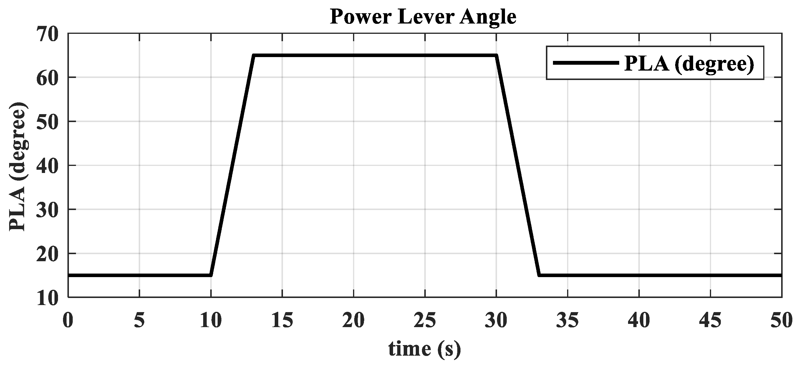
- Engine thrust should respond linearly to the power lever angle.
- The aircraft’s specific maneuverability and agility requirements.
2.2. Design of the Open-Loop Nozzle Control Circuit
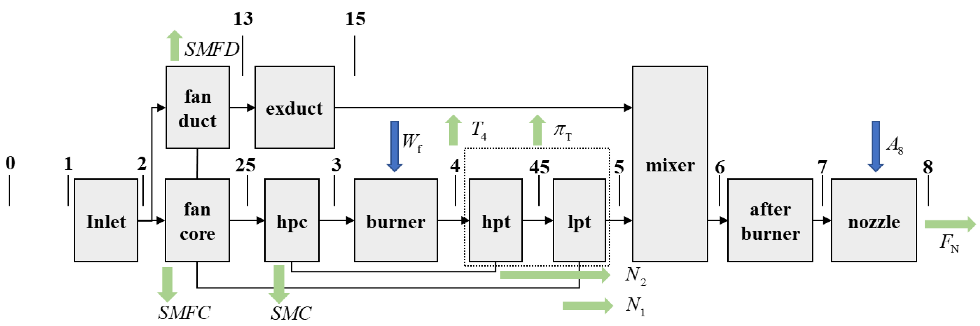
2.3. Modeling Description of the Turbofan Engine
2.4. Thrust Closed-Loop Model Adaptive Tracking μ-Synthesis Transient State Control Design Method
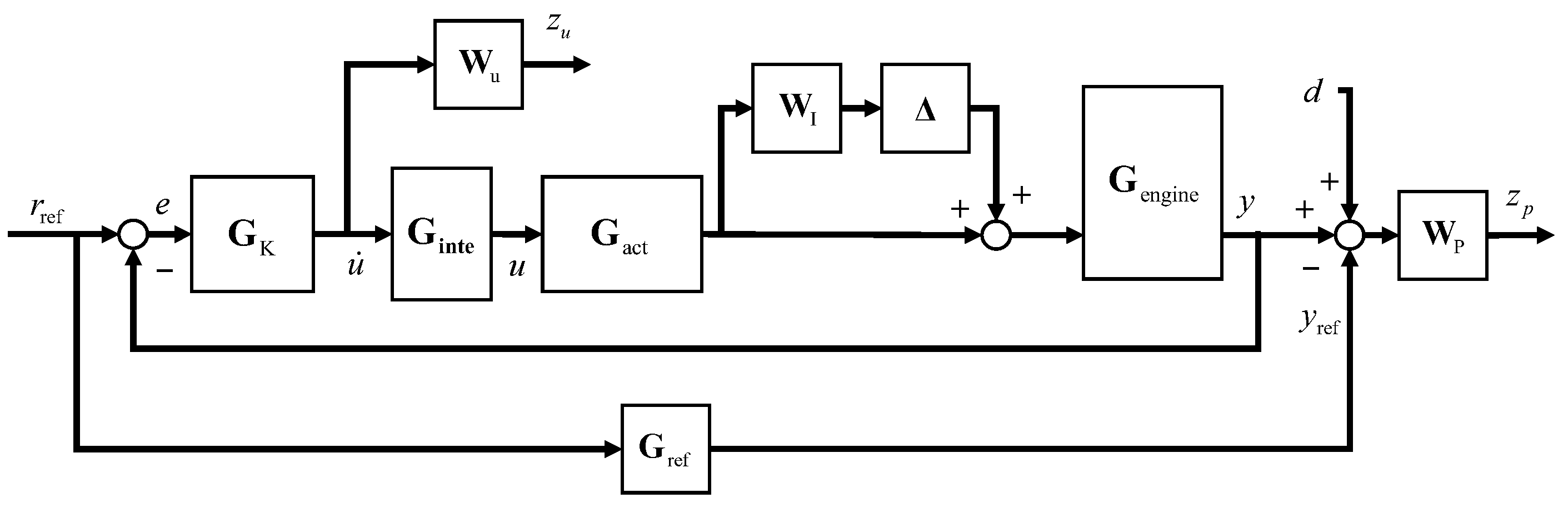
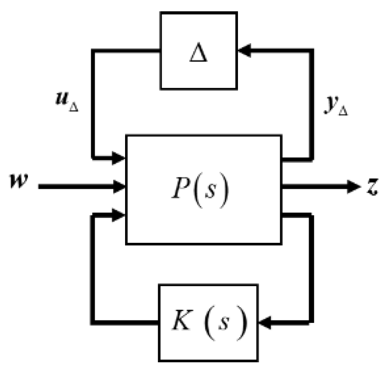
2.4.1. Augmented Controlled Plant Description
2.4.2. μ-Synthesis Direct Thrust Closed-Loop Control Structure
3. Simulation Verification and Discussions
3.1. Single-Variable Augmented Controlled Plant and Controller Design
3.2. Ground Transition Simulation
3.3. Low-Altitude and High-Mach Transition Simulation
3.4. High-Altitude and Low-Mach Transition Simulation
3.5. High-Altitude and High-Mach Transient State Simulation
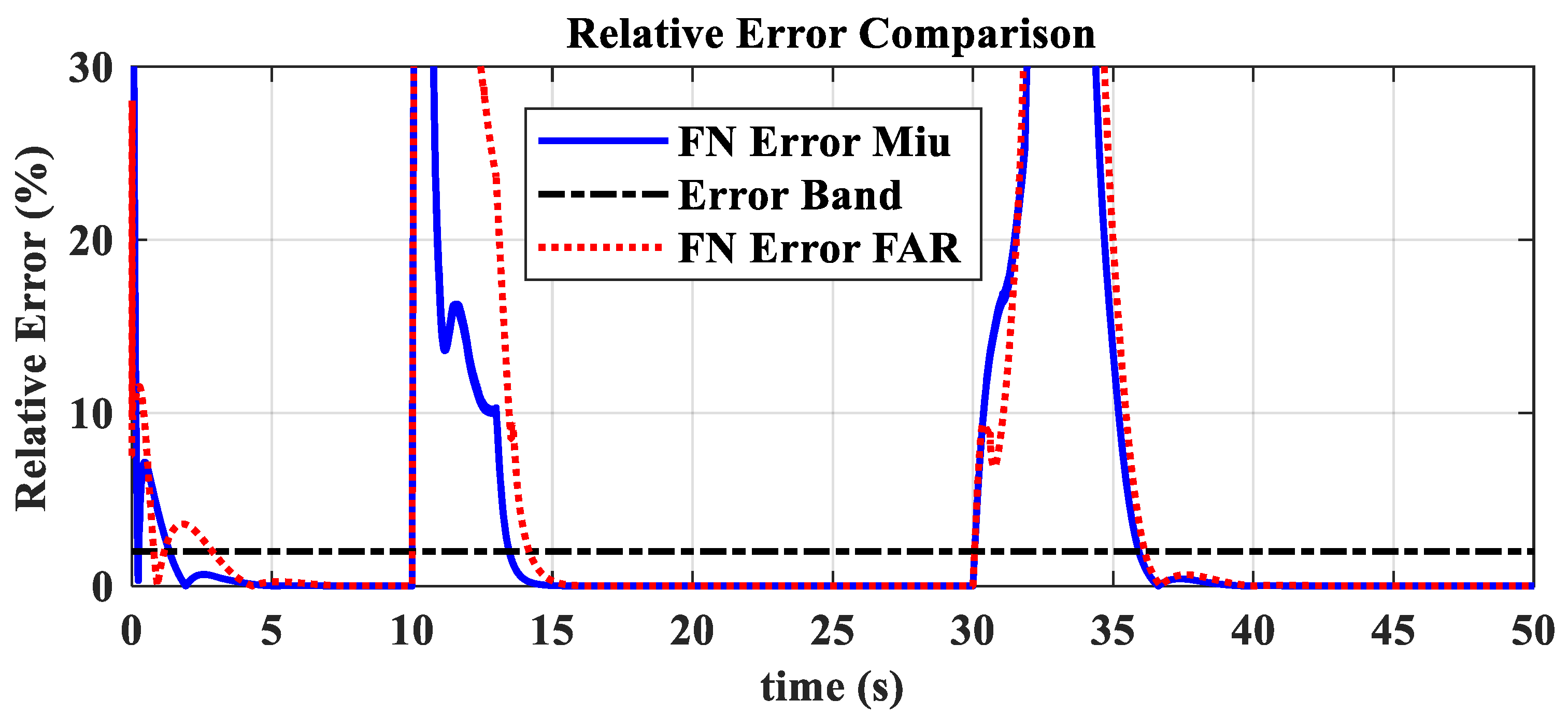
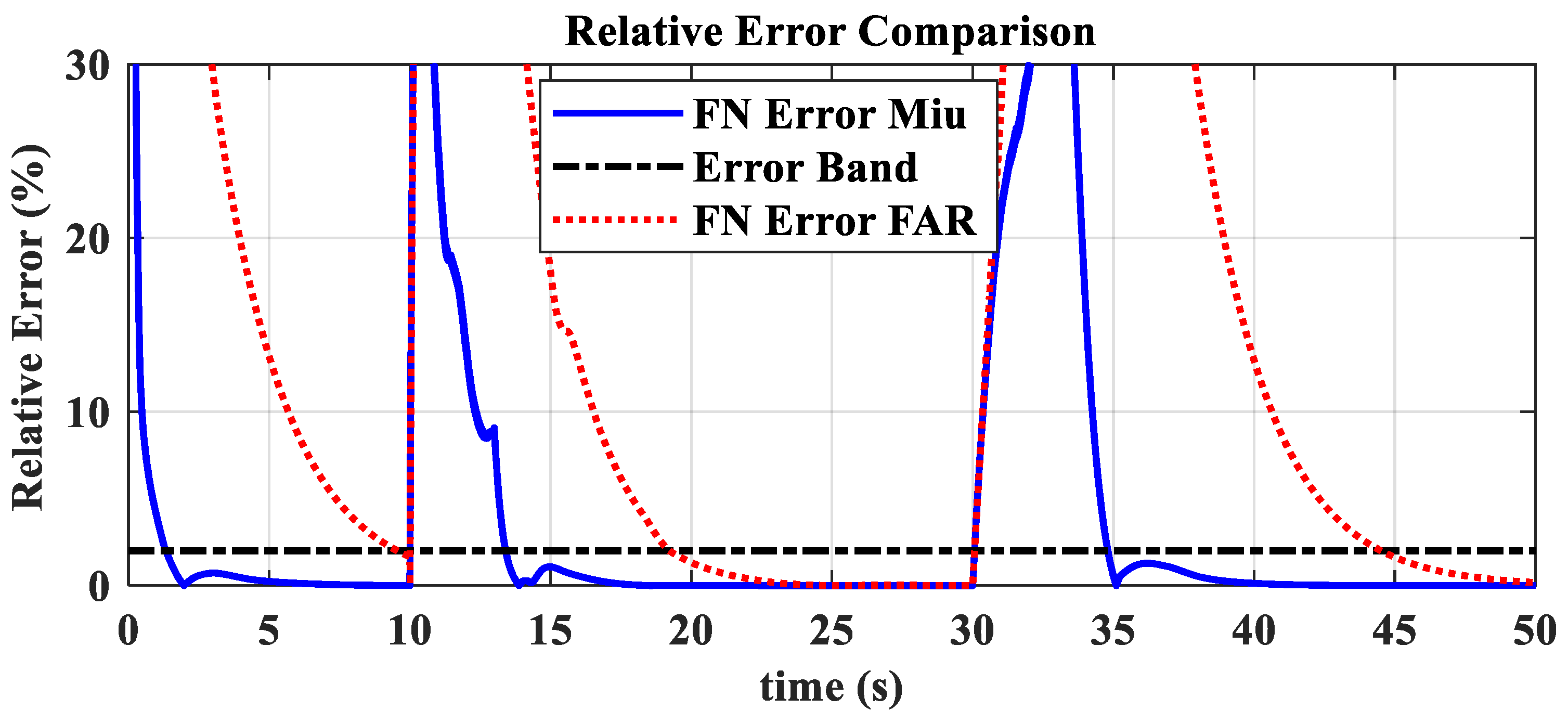
3.6. Comparative Validation of High and Low-Altitude Acceleration and Deceleration
4. Conclusions
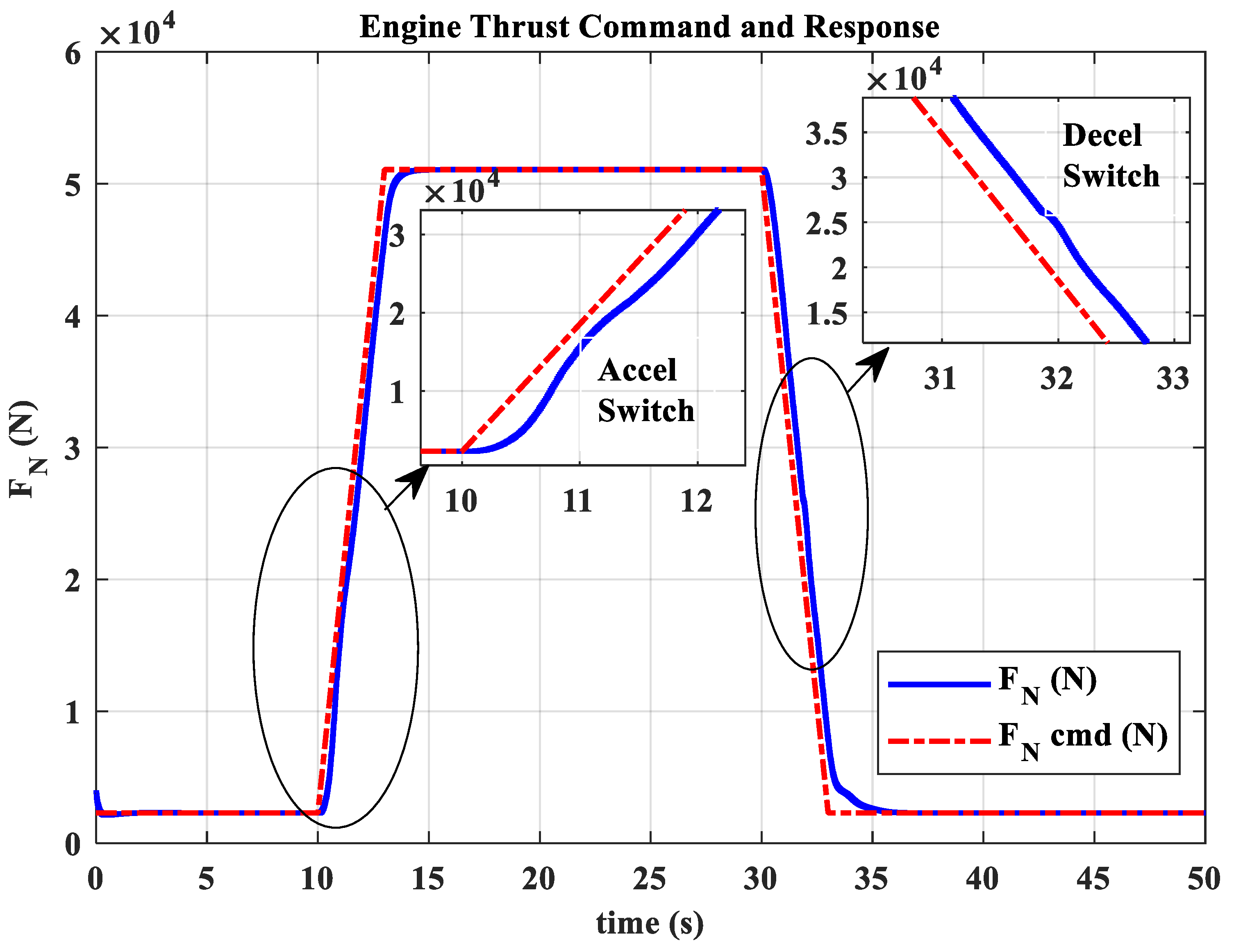
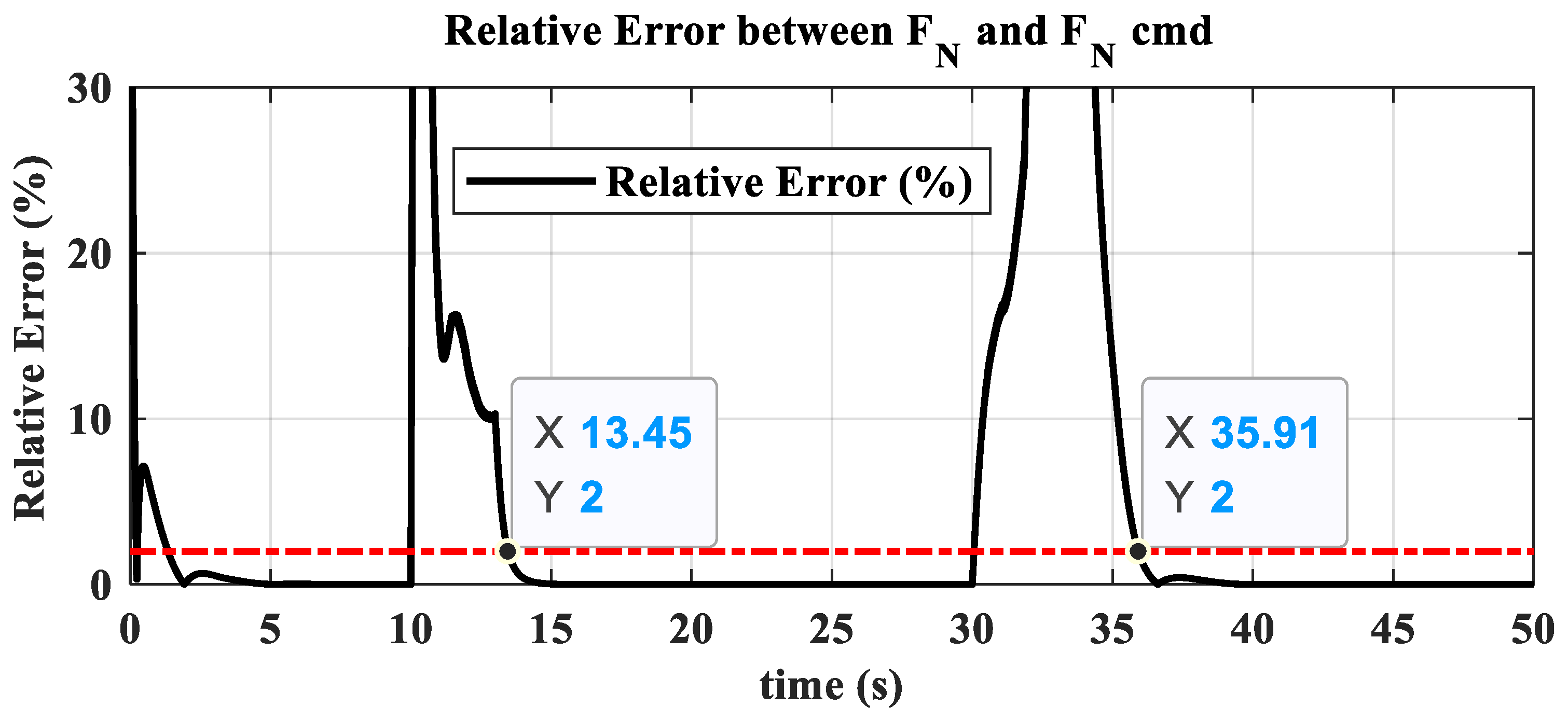
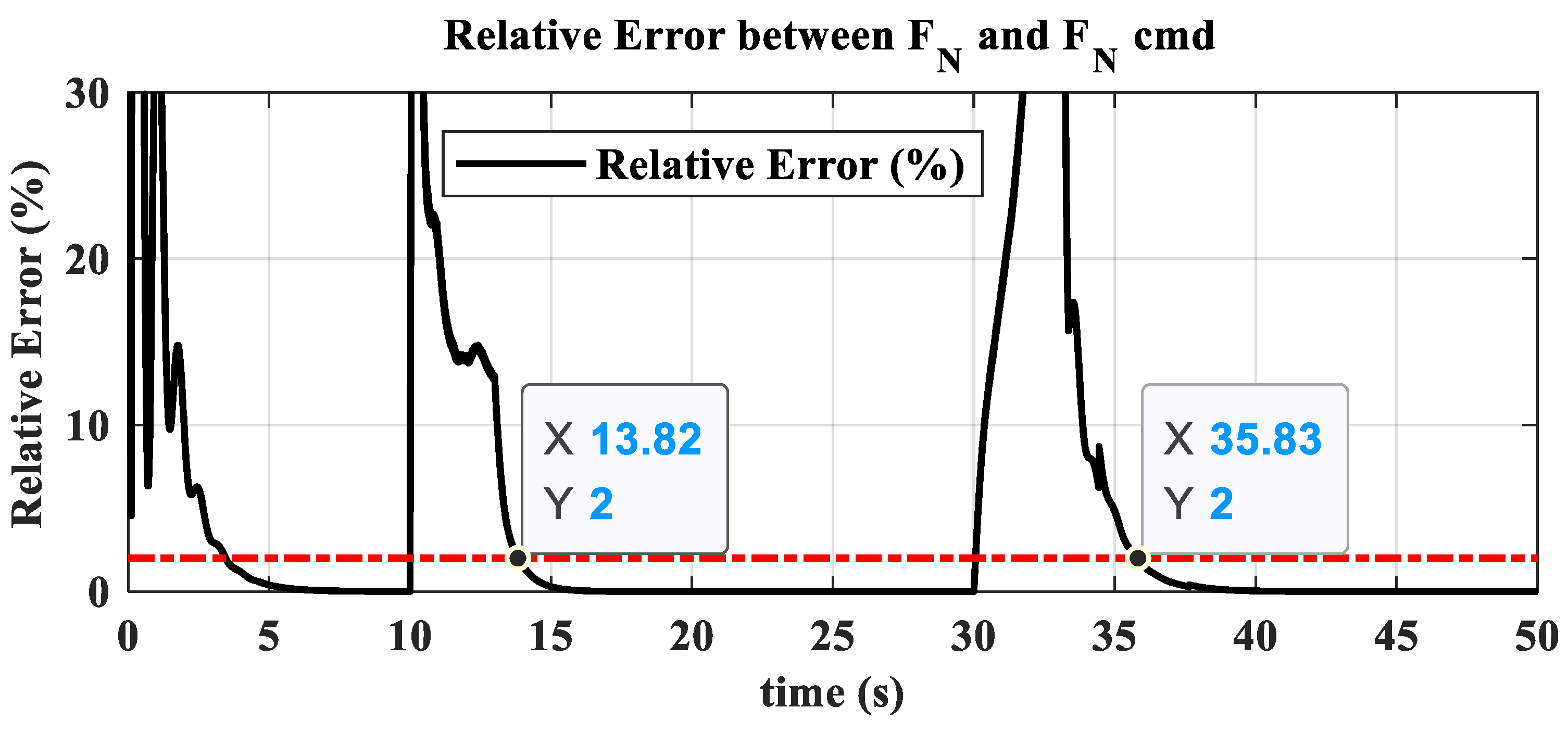
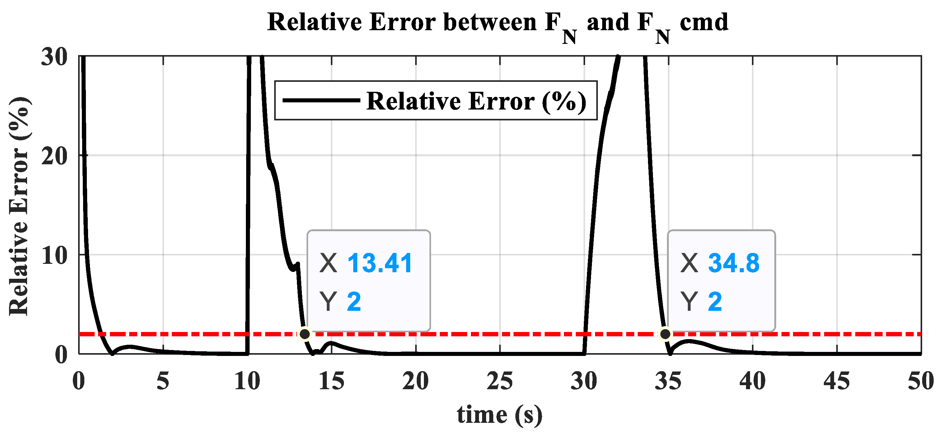
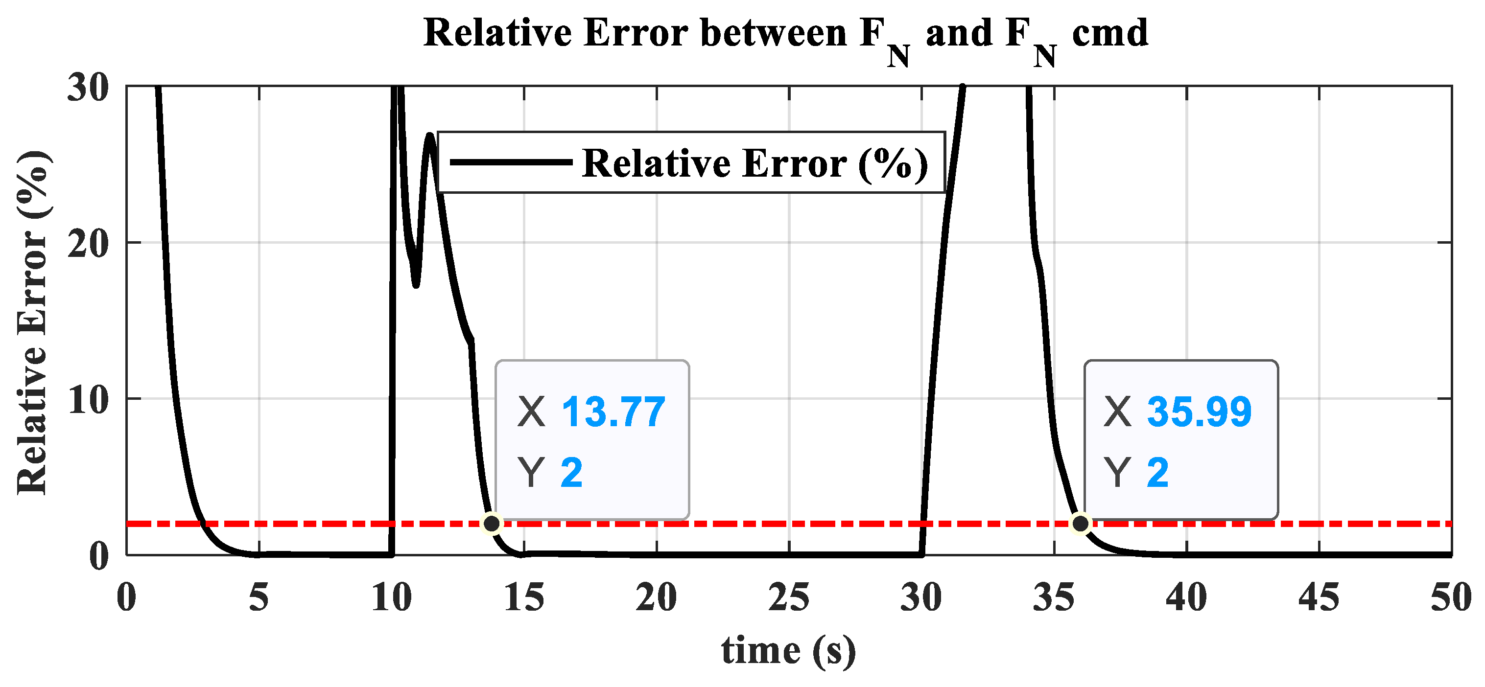
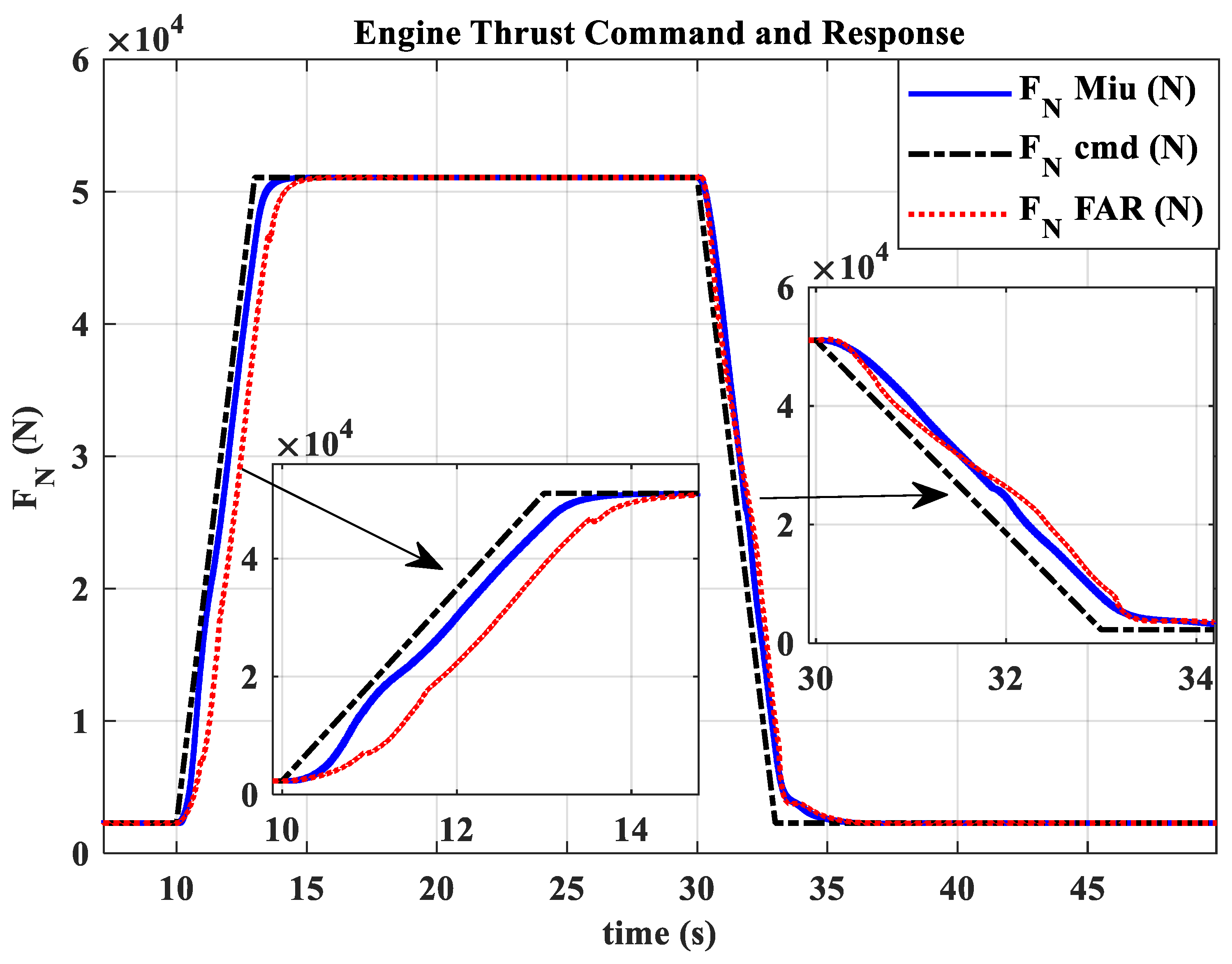
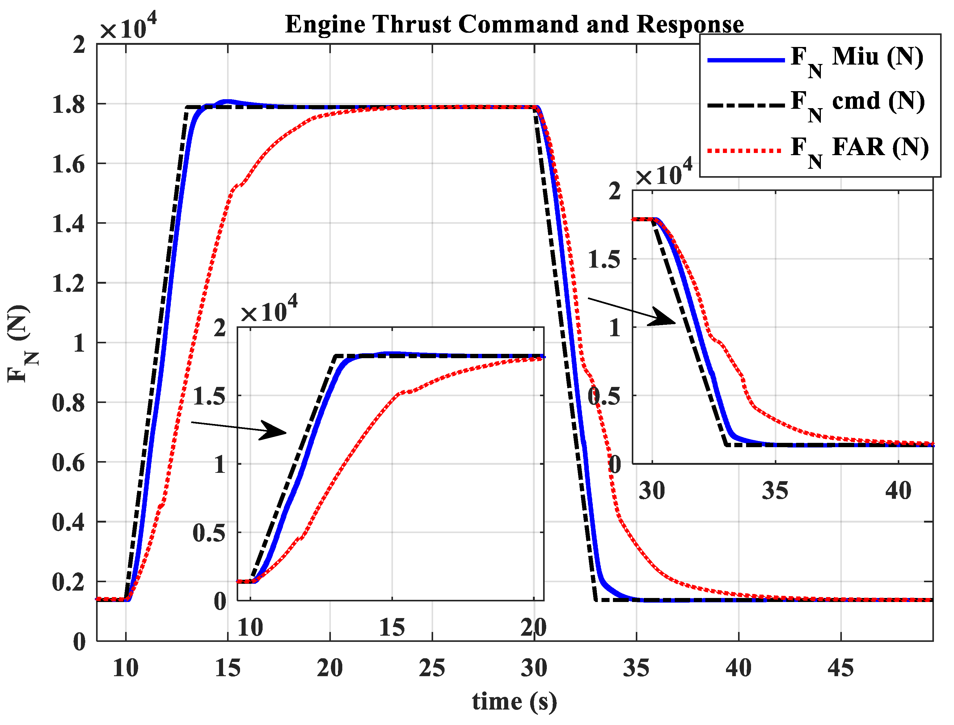
- The hybrid open-loop and closed-loop direct thrust control method ensures consistent robustness in acceleration and deceleration performance at different altitudes. The acceleration times range from 3.44 s to 3.84 s, with the standard deviation of acceleration time being 0.20; the deceleration times range from 4.83 s to 5.98 s, with the standard deviation of deceleration time being 0.55.
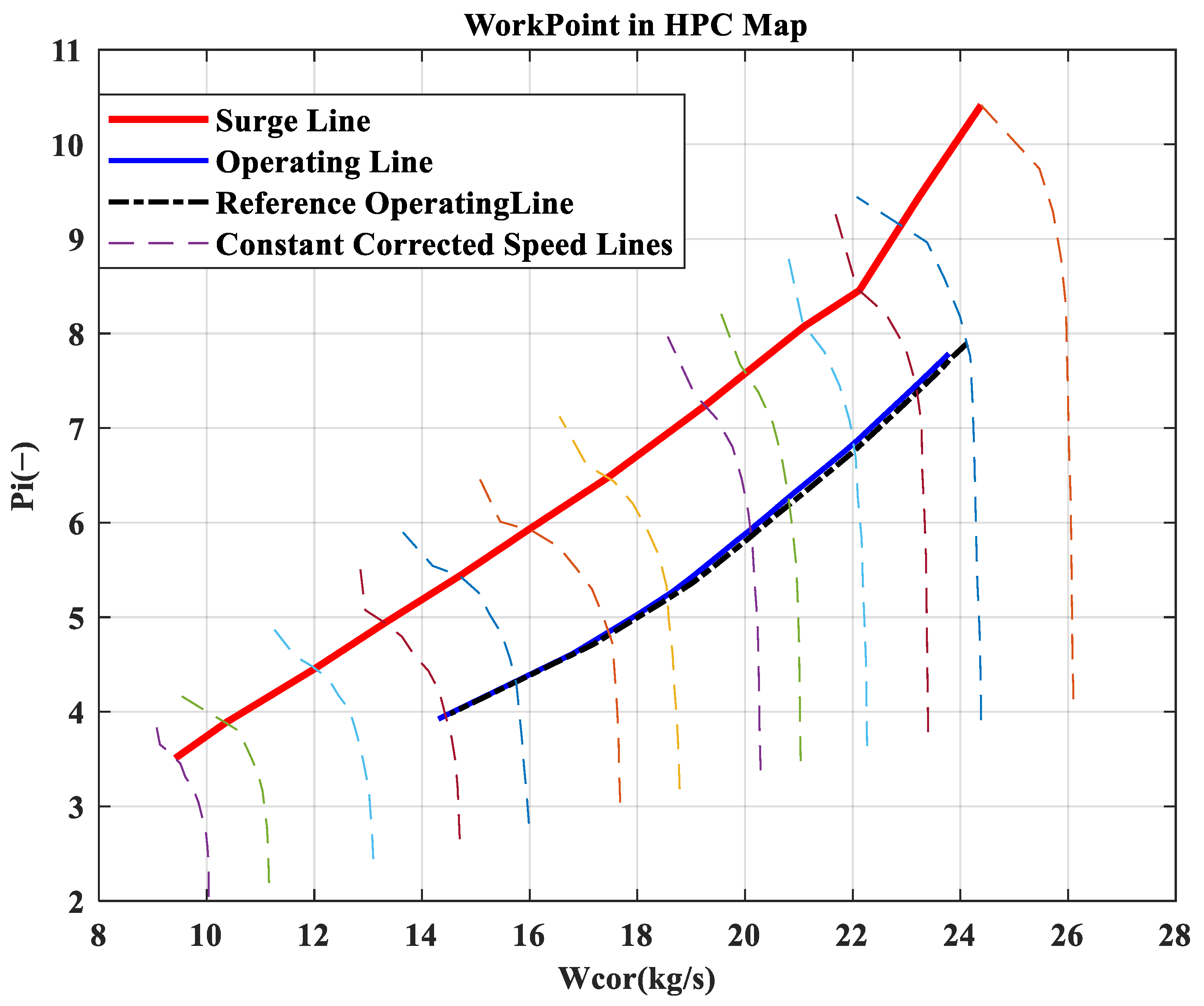
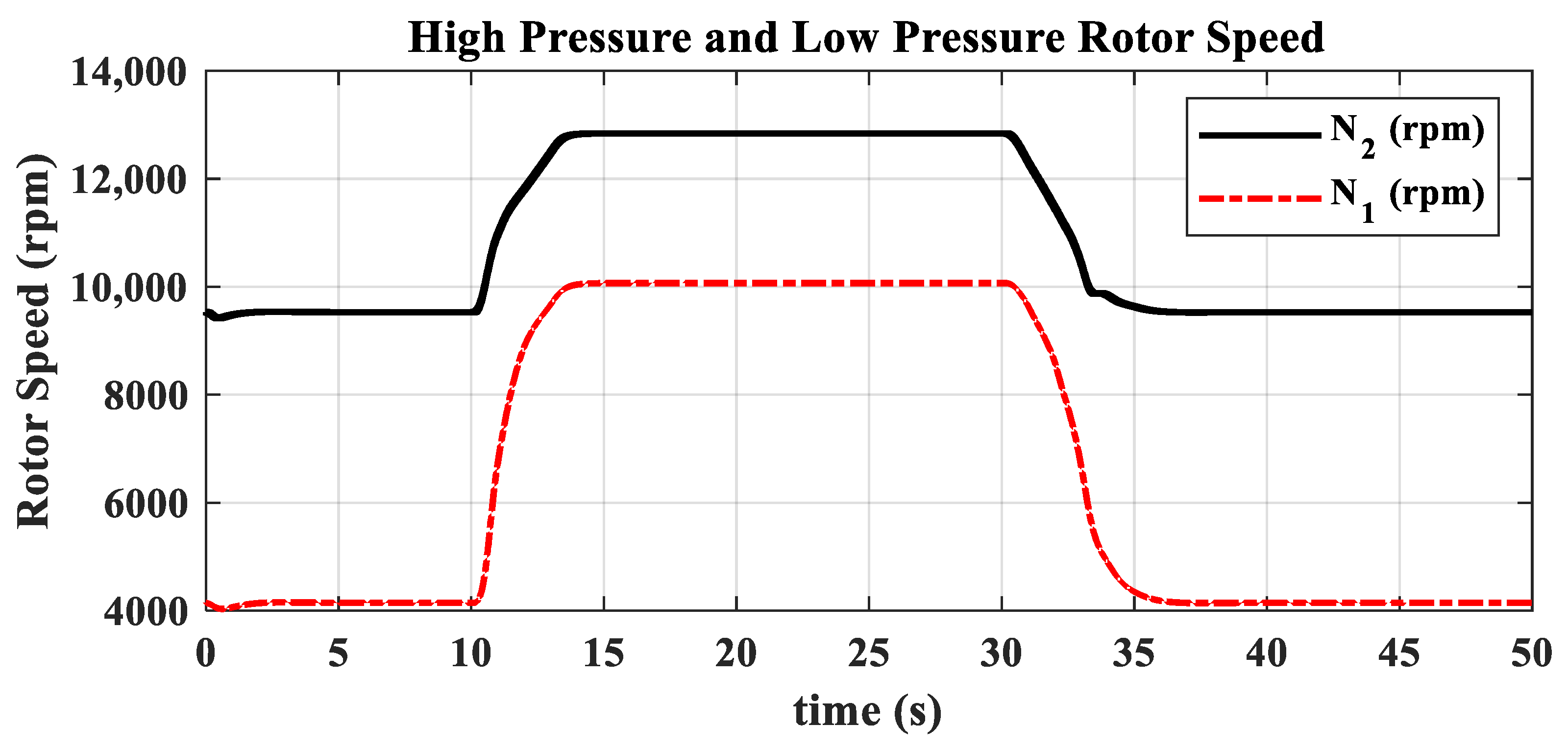
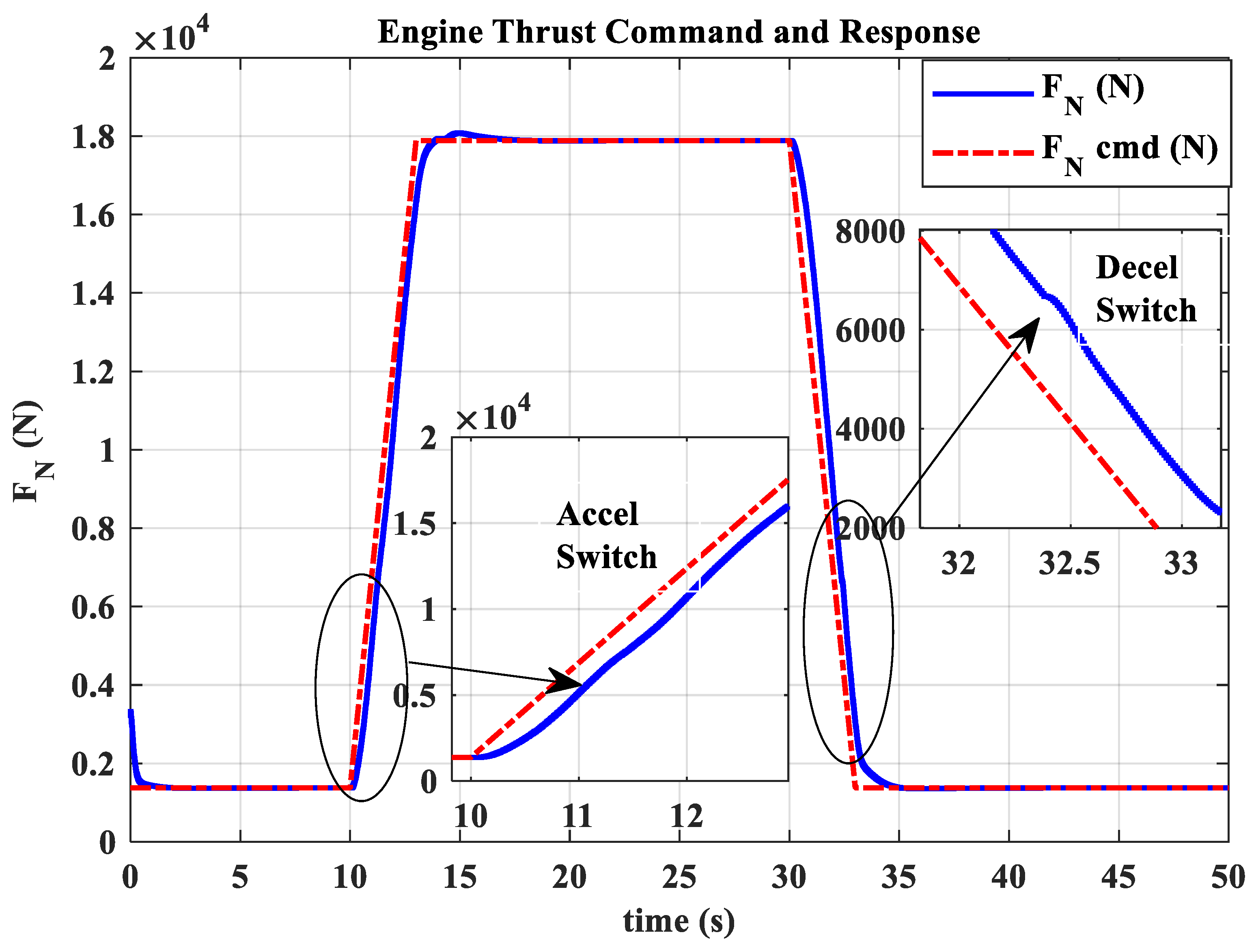
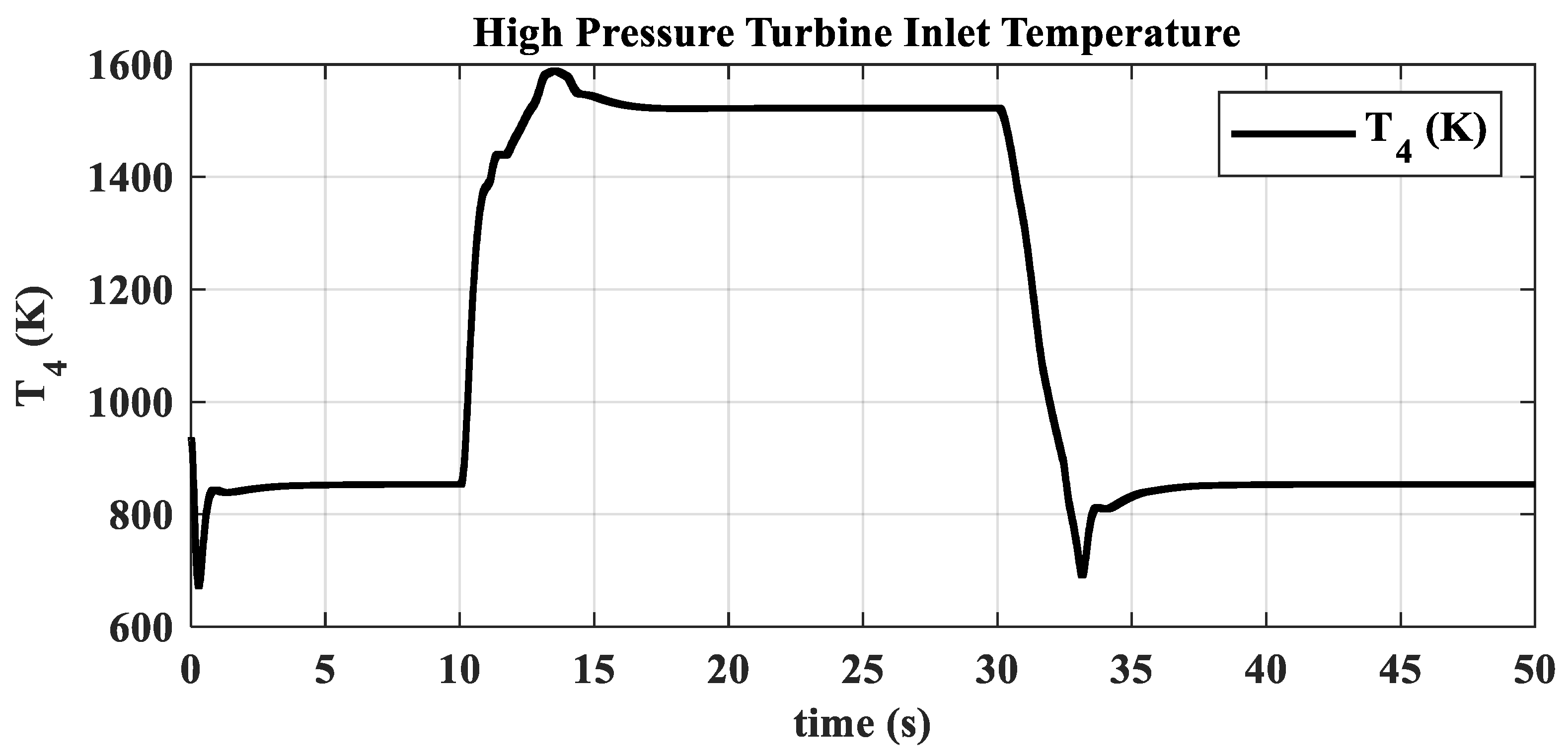
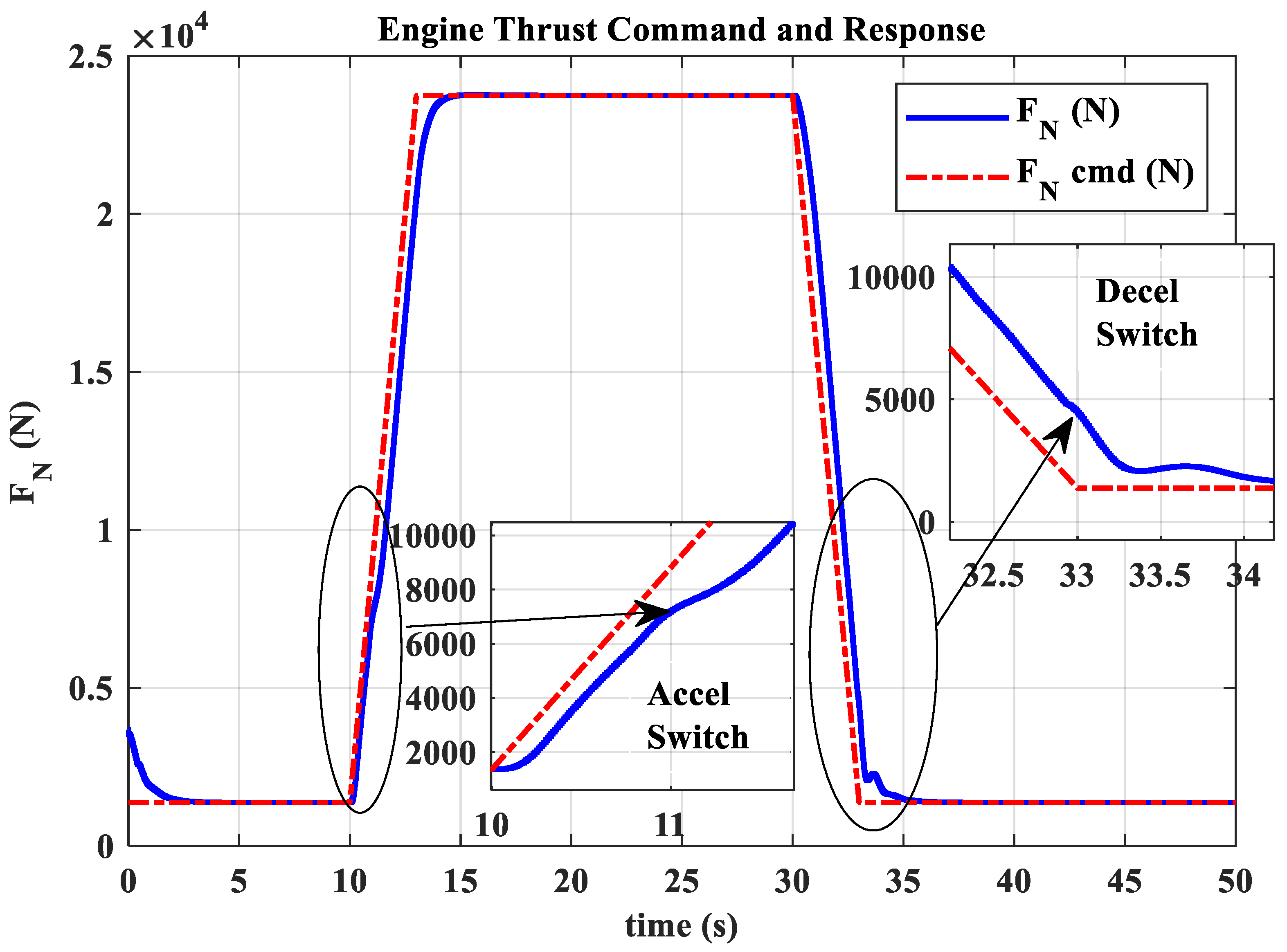
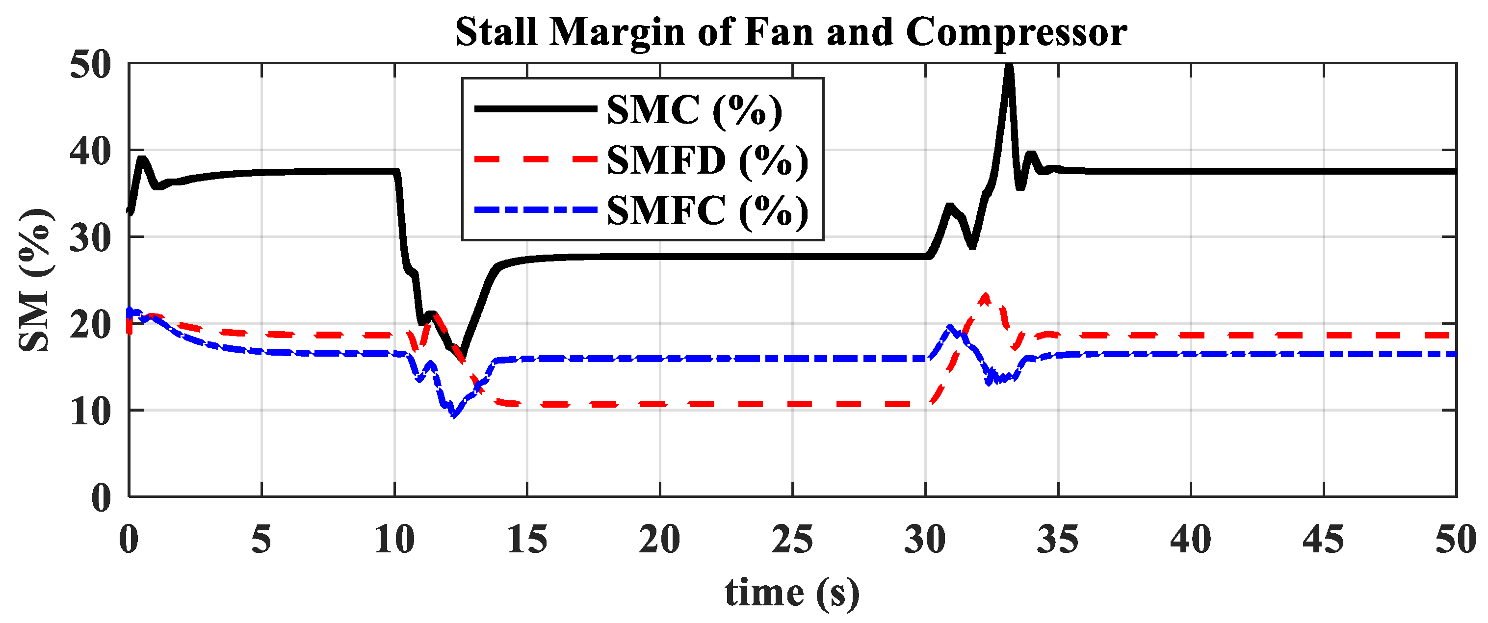
- The open-loop mode with nozzle area linearly varying according to the is suitable for acceleration and deceleration in low-power settings. Mode switching ensures that open-loop control in low-power settings maintains surge margin and reduces acceleration/deceleration times. In high-power settings, closed-loop control of adjusts the turbine pressure ratio, assisting in thrust adjustment and ensuring engine operation stays within safe limits, avoiding overheating, over-speeding, and surge.
- The thrust closed-loop model adaptive tracking μ-synthesis acceleration and deceleration control avoids the issue of inconsistent high- and low-altitude performance found in traditional fuel–air ratio control schemes.
Author Contributions
Funding
Data Availability Statement
Conflicts of Interest
Abbreviations
| FAR | Fuel–air ratio | DNN | Deep neural networks |
| LPV | Linear parameter varying | PI | Proportional–integral |
| APU | Auxiliary power unit | PLA | Power lever angle |
| AMB | Active magnetic bearing | Relative corrected speed of the high-pressure rotor (unit: %) | |
| ) | Main fuel flow rate (unit: kg/s) | ||
| H | Flight height (unit: km) | Ma | Flight Mach number |
| Engine net thrust ((unit: N)) | Turbine pressure ratio | ||
| Relative corrected speed of the high-pressure rotor at switching point (unit: %) | ) | ||
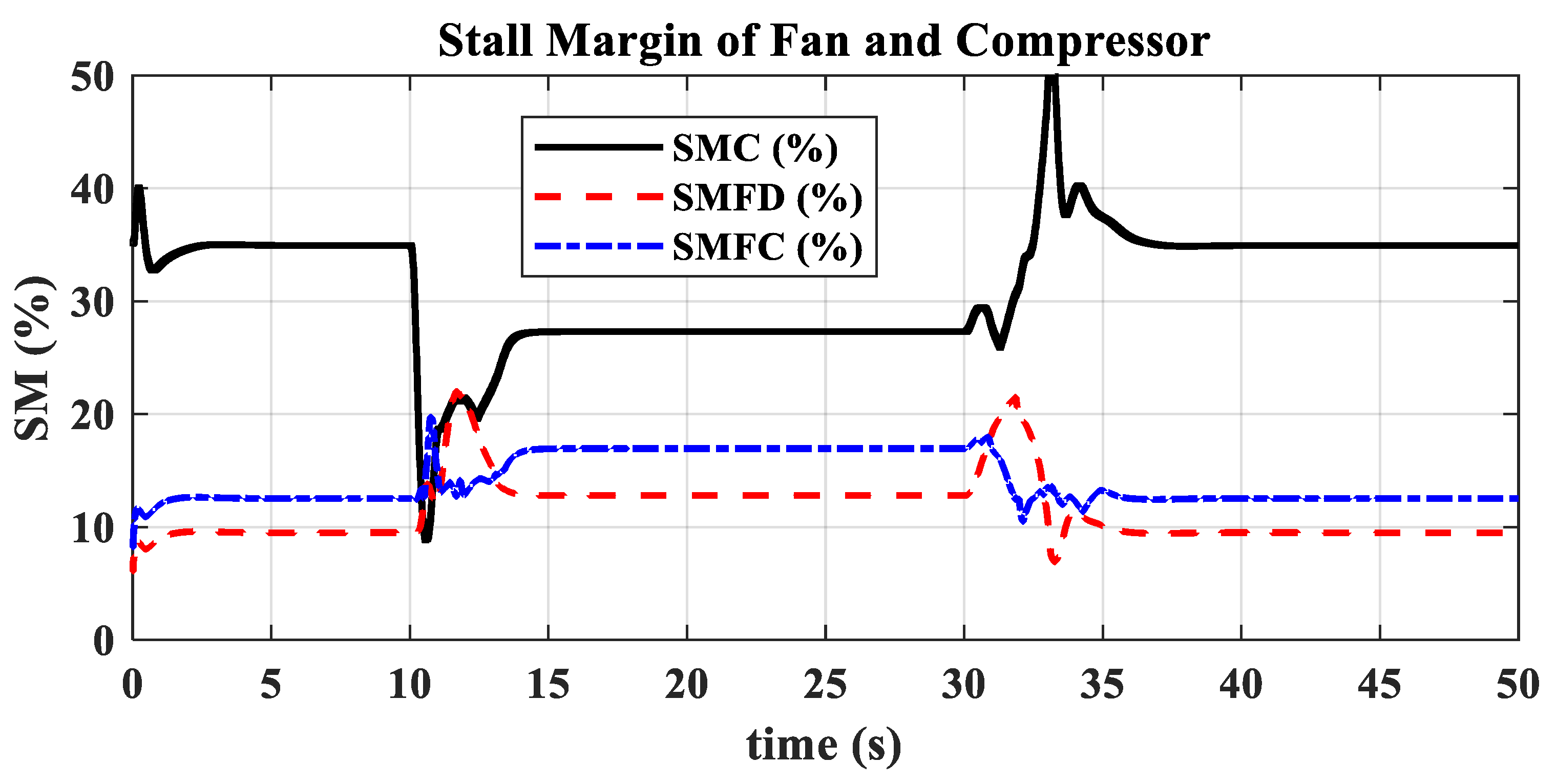
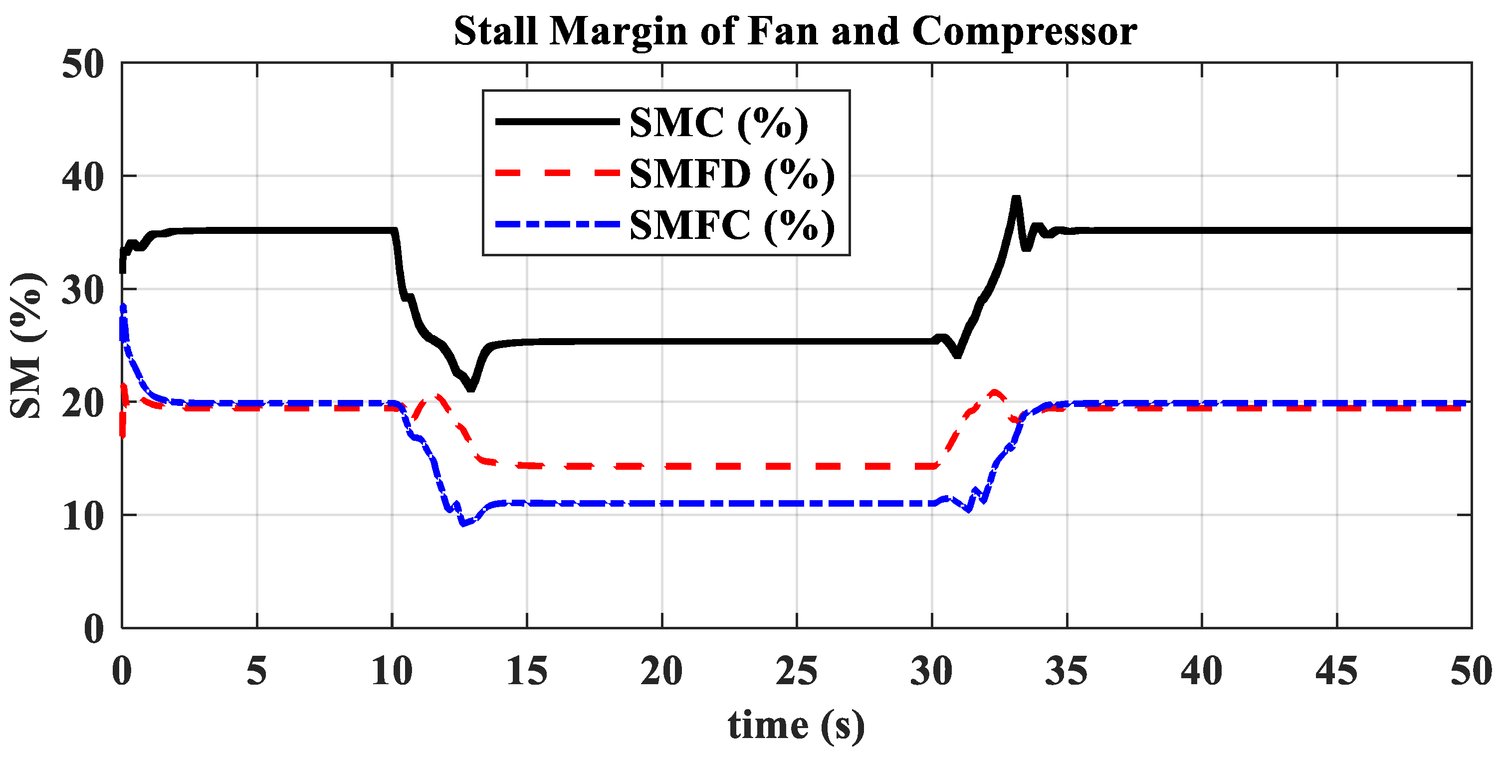
| ) | SMFD | Surge margin of fan bypass (unit: %) | |
| SMFC | Surge margin of fan core (unit: %) | SMC | Surge margin of high-pressure compressor (unit: %) |
| hpc | High pressure compressor | hpt | High pressure turbine |
| lpt | Low pressure turbine | P | Total pressure (unit: kPa) |
| W | Mass flow rate (unit: kg/s) | Combustion efficiency | |
| V | Velocity (unit: m/s) | Cp | Constant-pressure specific heat capacity (unit: J/K) |
| Low level calorific value of the fuel (unit: J/kg) | Weighting function for suppressing controller output energy | ||
| Transfer function matrix of the reference model | Unstructured uncertainty matrix | ||
| Weighting function for tracking model error sensitivity | ru | Relative uncertainty | |
| uncertainty bound weighting function | Weighting function adjustment factor | ||
| Performance adjustment factors | Control energy suppression adjustment factor |
References
- Jaw, L.C.; Mattingly, J.D. Aircraft Engine Controls: Design, System Analysis, and Health Monitoring; AIAA Education Series; American Institute of Aeronautics and Astronautics, Inc.: Reston, VA, USA, 2009; ISBN 978-1-60086-705-7. [Google Scholar]
- Jaw, L.; Garg, S. Propulsion Control Technology Development in the United States A Historical Perspective; NASA: Washington, DC, USA, 2005. [Google Scholar]
- MacIsaac, B.; Langton, R. Gas Turbine Propulsion Systems; Aerospace series; Wiley; American Institute of Aeronautics and Astronautics: Chichester, UK; Reston, VA, USA, 2011; ISBN 978-0-470-06563-1. [Google Scholar]
- Walsh, P.P.; Fletcher, P. Gas Turbine Performance, 2nd ed.; [repr.].; Blackwell Science: Oxford, UK, 2008; ISBN 978-0-632-06434-2. [Google Scholar]
- Fan, S. Aeroengine Control (Volume Two), 1st ed.; Northwestern Polytechnic University Press: Xi’an, China, 2008; ISBN 978-7-5612-2161-7. [Google Scholar]
- Gold, H.; Seldner, K. Computer and Engine Performance Study of a Generalized Parameter Fuel Control for Jet Engines; NASA: Washington, DC, USA, 1970. [Google Scholar]
- Liu, Z.; Zheng, Q.; Liu, M.; Hu, C.; Zhang, H. Improvement Method of Turbofan Engine Full-Envelope Acceleration Control Schedule. J. Propuls. Technol. 2022, 43, 346–353. [Google Scholar] [CrossRef]
- Yu, B.; Cao, C.; Shu, W.; Hu, Z. A New Method for the Design of Optimal Control in the Transient State of a Gas Turbine Engine. IEEE Access 2017, 5, 23848–23857. [Google Scholar] [CrossRef]
- Shi, Y.; Tu, Q.; Cai, Y.; Qiu, C.; Tan, Z. Optimum desing method of acceleration and deceleration control schedule for gas turbine engine. J. Aerosp. Power 2013, 28, 2567–2571. [Google Scholar] [CrossRef]
- Wang, R.; Zhou, W.; Huang, J.; Luo, J.; Song, Q. Fixed states method of turbofan engine acceleration and deceleration control law design. J. Aerosp. Power 2022, 37, 2896–2904. [Google Scholar] [CrossRef]
- Gao, W.; Zhou, X.; Pan, M.; Zhou, W.; Lu, F.; Huang, J. Acceleration Control Strategy for Aero-Engines Based on Model-Free Deep Reinforcement Learning Method. Aerosp. Sci. Technol. 2022, 120, 107248. [Google Scholar] [CrossRef]
- Gu, Z.; Pang, S.; Li, Y.; Li, Q.; Zhang, Y. Turbo-Fan Engine Acceleration Control Schedule Optimization Based on DNN-LPV Model. Aerosp. Sci. Technol. 2022, 128, 107797. [Google Scholar] [CrossRef]
- Zhang, X.; Wang, Z.; Xiao, B.; Ye, Y. A Neural Network Learning-Based Global Optimization Approach for Aero-Engine Transient Control Schedule. Neurocomputing 2022, 469, 180–188. [Google Scholar] [CrossRef]
- Morrison, T.; Howlett, J.J.; Zagranski, R.D. Adaptive Fuel Control Feasibility Investigation for Helicopter Applications; American Society of Mechanical Engineers Digital Collection: New York, NY, USA, 1982. [Google Scholar]
- Howlett, J.J.; Morrison, T.; Zagranski, R.D. Adaptive Fuel Control for Helicopter Applications. J. Am. Helicopter Soc. 1984, 29, 43–54. [Google Scholar] [CrossRef]
- Wang, X.; Dang, W.; Li, Z.; Hu, Z.; Yin, K.; Zhang, R. A Design Method of N-dot Transient State PI Control Laws. Aeroengine 2015, 41, 1–5. [Google Scholar] [CrossRef]
- Huang, L.; Yin, K.; Yang, W.; Guo, Y. Design of Acceleration Controller to a Turbofan Engine Using N-dot Method. Aeroengine 2017, 43, 26–30. [Google Scholar] [CrossRef]
- Yang, F.; Peng, K.; Wang, W.; Bai, J.; Zhao, Z.; Mao, N. Research and testing verification of N-Dot acceleration control for an auxiliary power unit. Gas Turbine Exp. Res. 2020, 33, 13–16. [Google Scholar]
- Peng, K.; Yang, F.; Zhang, Z.; Jiao, C. Design and Test Verification of Acceleration Control for the Auxiliary Power Unit Based on N-Dot Acceleration Control Law. J. Phys. Conf. Ser. 2020, 1510, 012006. [Google Scholar] [CrossRef]
- Li, Y.; Li, Q.; Zhang, X.; Pang, S.; Zhang, Y. N-dot control method of turbofan engine based on active switching logic. J. Beijing Univ. Aeronaut. Astronaut. 2022, 49, 3156–3166. [Google Scholar] [CrossRef]
- Liu, J.; Wang, X.; Zhu, M.; Miao, K. Multivariable Adaptive Control Method for Turbofan Engine With Dynamic and Input Uncertainties. J. Eng. Gas Turbines Power 2021, 143, 071027. [Google Scholar] [CrossRef]
- Zhao, H.; Liao, Z.; Liu, J.; Li, M.; Liu, W.; Wang, L.; Song, Z. A Highly Robust Thrust Estimation Method with Dissimilar Redundancy Framework for Gas Turbine Engine. Energy 2022, 245, 123255. [Google Scholar] [CrossRef]
- Litt, J.S.; Sowers, T.S.; Corporation, A.; Garg, S. A Retro-Fit Control Architecture to Maintain Engine Performance with Usage. In Proceedings of the 18th ISABE Conference, Beijing, China, 1 September 2007. [Google Scholar]
- Doyle, J.C. Analysis of Feedback Systems with Structured Uncertainty. IEE Proc. D Control. Theory Appl. 1982, 129, 242–250. [Google Scholar] [CrossRef]
- Pesch, A.H.; Smirnov, A.; Pyrhönen, O.; Sawicki, J.T. Magnetic Bearing Spindle Tool Tracking Through μ-Synthesis Robust Control. IEEEASME Trans. Mechatron. 2015, 20, 1448–1457. [Google Scholar] [CrossRef]
- Pirat, C.; Ankersen, F.; Walker, R.; Gass, V. H-Infinity and μ -Synthesis for Nanosatellites Rendezvous and Docking. IEEE Trans. Control Syst. Technol. 2020, 28, 1050–1057. [Google Scholar] [CrossRef]
- Long, Y.; Wang, X.; Zhao, W.; Liu, J. Dual-Loop μ-Synthesis Direct Thrust Control for Turbofan Engines. Symmetry 2024, 16, 944. [Google Scholar] [CrossRef]
- GSP Development Team. GSP 11 User Manual. Available online: https://www.scribd.com/document/214970234/GSP-UM-11-pdf (accessed on 21 December 2024).
- Yang, S. Sliding Mode Control of Aircraft Engines. Ph.D. Thesis, Beihang University, Beijing, China, 2020. [Google Scholar]
- Gu, D.-W.; Petkov, P.H.; Konstantinov, M.M. Robust Control Design with MATLAB®; Advanced Textbooks in Control and Signal Processing; Springer: London, UK, 2013; ISBN 978-1-4471-4681-0. [Google Scholar]
- Skogestad, S.; Postlethwaite, I. Multivariable Feedback Control: Analysis and Design, 2nd ed.; Wiley: Chichester, UK, 2005; ISBN 978-0-470-01168-3. [Google Scholar]
- Alfi, A.; Khosravi, A.; Lari, A. Swarm-Based Structure-Specified Controller Design for Bilateral Transparent Teleoperation Systems via μ Synthesis. IMA J. Math. Control Inf. 2014, 31, 111–136. [Google Scholar] [CrossRef]


| Definition | Variables | Definition | Variables |
|---|---|---|---|
| Fan Inlet Total Temperature | Ambient Static Pressure | ||
| Fan Inlet Total Pressure | Fan Bypass Outlet Total Pressure | ||
| Fan Core Outlet Total Pressure | HPC Outlet Total Pressure | ||
| HPT Outlet Total Pressure | LPT Outlet Total Pressure | ||
| LP Rotor Speed | HP Rotor Speed |
| Flight Condition | Miu Acc. Time(s) | FAR Acc. Time(s) | Miu Dec. Time(s) | FAR Dec. Time(s) | Engine Inlet Total Temperature (K) |
|---|---|---|---|---|---|
| Ground (H = 0 km, Ma = 0) | 3.45 | 4.17 | 5.91 | 6.12 | 288.15 |
| Low altitude, High Mach number (H = 0 km, Ma = 0.8) | 3.84 | 3.90 | 5.82 | 5.86 | 325.03 |
| High altitude, Low Mach number (H = 9 km, Ma = 0.3) | 3.44 | 9.21 | 4.81 | 14.48 | 233.78 |
| High altitude, High Mach number (H = 11 km, Ma = 1.2) | 3.74 | 6.73 | 5.98 | 10.28 | 279.05 |
Disclaimer/Publisher’s Note: The statements, opinions and data contained in all publications are solely those of the individual author(s) and contributor(s) and not of MDPI and/or the editor(s). MDPI and/or the editor(s) disclaim responsibility for any injury to people or property resulting from any ideas, methods, instructions or products referred to in the content. |
© 2024 by the authors. Licensee MDPI, Basel, Switzerland. This article is an open access article distributed under the terms and conditions of the Creative Commons Attribution (CC BY) license (https://creativecommons.org/licenses/by/4.0/).
Share and Cite
Long, Y.; Wang, X.; Liu, J. A Hybrid Open/Closed-Loop μ Control Method for Achieving Consistent Transient Performance in Turbofan Engines. Actuators 2024, 13, 531. https://doi.org/10.3390/act13120531
Long Y, Wang X, Liu J. A Hybrid Open/Closed-Loop μ Control Method for Achieving Consistent Transient Performance in Turbofan Engines. Actuators. 2024; 13(12):531. https://doi.org/10.3390/act13120531
Chicago/Turabian StyleLong, Yifu, Xi Wang, and Jiashuai Liu. 2024. "A Hybrid Open/Closed-Loop μ Control Method for Achieving Consistent Transient Performance in Turbofan Engines" Actuators 13, no. 12: 531. https://doi.org/10.3390/act13120531
APA StyleLong, Y., Wang, X., & Liu, J. (2024). A Hybrid Open/Closed-Loop μ Control Method for Achieving Consistent Transient Performance in Turbofan Engines. Actuators, 13(12), 531. https://doi.org/10.3390/act13120531