Article

Free Vibration Analysis of Hydraulic Quick Couplings Considering Fluid–Structure Interaction Characteristics

1
School of Mechanical Engineering, University of Science and Technology Beijing, Beijing 100083, China
2
School of Civil and Resources Engineering, University of Science and Technology Beijing, Beijing 100083, China
*
Author to whom correspondence should be addressed.
Actuators 2024, 13(12), 515; https://doi.org/10.3390/act13120515
Submission received: 9 October 2024 / Revised: 4 November 2024 / Accepted: 9 December 2024 / Published: 11 December 2024
(This article belongs to the Section Control Systems)

Abstract

:
As an important component of the automatic hydraulic quick coupling device (AHQCD) on rescue vehicles, the hydraulic quick couplings (HQCs) are used to rapidly dock hydraulic lines and transport fluid while changing and operating hydraulic working tools. However, during tool operation at rescue sites, pressure pulsations at multiple frequencies in the hydraulic lines can coincide with the natural frequencies of the HQCs, potentially causing resonance that severely affects the stability of fluid conveying and damages the connection of hydraulic lines accidentally. To investigate the natural frequencies of the HQCs with upstream and downstream lines, the characteristics of fluid–structure interaction were considered between the poppets and the fluid in this study, and an equivalent stiffness model of the fluid domain was derived based on the fluid compressibility. A dynamic model, along with 6-DOF equations for the system, was established, and the natural frequencies and mode vectors were determined by free vibration analysis. In addition, the effects of working pressure, air content, and stiffness of the springs on the natural frequency of the HQC system were analyzed. The results show the natural frequency increases with a higher working pressure and lower air content, while the effect of spring stiffness on natural frequencies varies with different modes. Furthermore, the proposed model is validated by experimental pressure signals, showing good agreement, with an average error of 2.7% for the first-order natural frequency. This paper presents a theoretical method for improving the stability of fluid transport when operating various hydraulic tools under complex rescue conditions.

1. Introduction

China is among the countries most severely affected by geohazards globally, characterized by diverse types, a widespread geographic distribution, a high occurrence frequency, significant destructiveness, and challenges in effective prediction. Therefore, the ability to immediately and efficiently carry out emergency rescue operations during disasters is essential [1,2]. Rescue vehicles currently play a significant role at disaster sites, including demolishing concrete structures, clearing landslide rocks, and repairing damaged roads. However, these rescue vehicles are typically equipped with only one type of hydraulic working tool, providing a single operational function, which limits their efficiency and performance during rescue operations.
To address this issue, automatic hydraulic quick coupling devices (AHQCDs) have been designed and attempted to be installed on rescue vehicles, enabling quick tool changes within minutes and allowing a single vehicle to perform multiple tasks [3,4]. During the tool-changing process, the hydraulic lines must be docked with the mechanical frame simultaneously, presenting a technical challenge that has been extensively studied. Liebherr and Oilquick have developed automatic hydraulic quick coupling systems (AHQCSs), including the Likufix and OQ series, respectively [5,6,7]. Specialized hydraulic quick couplings (HQCs) have been used to simultaneously dock hydraulic lines during tool changes, with an average time of 60 s [8]. The K100 boom change system has been developed by Komatsu for replacing booms while simultaneously connecting the hydraulic lines in high-reach demolition machines [9]. Yun Chao [10,11] provided a comprehensive review of specialized HQCs, examining their applicability in hydraulic quick coupling systems. He proposed a solution for automatic docking of HQCs that balances cost and manufacturing complexity.
However, the proposed docking systems are rarely applied in practical rescue scenarios or heavy-load conditions. The HQCs simultaneously endure upstream pressure pulsations from a pump [12,13], downstream hydraulic impulses generated by the tools [14,15], and internal vortexes caused by complex geometric structures during fluid transport [16]. Resonance may occur in the docking system when the frequency of an excitation is close to the natural frequency of the HQCs, significantly amplifying hydraulic pulsation and potentially damaging the entire docking lines [17,18]. Additionally, resonance can increase the amplitude of vibrations in the internal poppets and exacerbate wear of the seals, leading to system leakage [19,20]. Therefore, to ensure a reliable connection of hydraulic lines, it is essential to first determine the natural frequency of the HQC system to prevent resonance.
The research on hydraulic pipeline modeling is abundant, including fluid network theory, the finite element method, the semi-analytical method, and others [21,22,23]. Pan et al. [21] developed a natural frequency model of a self-resonating water jet based on fluid network theory and experimentally determined the natural frequency ranges of low-frequency pulsation and high-frequency oscillations in the fluid network and nozzle. Cao [22] investigated a hydraulic-line system with connected hoses, determining the equivalent support stiffness of the hoses using a frequency response function, and established a dynamic model of the system based on the finite element method, analyzing the natural frequencies and mode shapes of the system under different pressures. Ding et al. [23] studied the free vibration characteristics of high-speed pipelines using a combination of analytical and numerical methods, analyzing the impact of nonlinear stiffness on the natural frequencies.
Different from a simple pipeline, the movable poppet element was contained in a docking system, which complicates the analysis of the natural frequency of the hydraulic line. Specifically, the HQCs have a very compact configuration with complex and narrow valve channels. As hydraulic fluid flows through the narrow channels, the poppets inside are gradually accelerated by significantly varying pressure caused by the strong geometric constraint, leading to vibration of poppets. This vibration of the poppets, in turn, affects the velocity and pressure distribution within the flow field, further intensifying the poppet vibration and resulting in a fluid–structure interaction effect. Therefore, the dynamic behavior of the poppets should be considered primarily when studying the natural characteristics of a docking system in hydraulic lines. Yuan et al. [24,25] considered the fluid–structure interaction characteristics between the spray core and the fluid in the fire-fighting jet system, and they established a 7-DOF free vibration equation based on the equivalent stiffness model of the upstream fluid and using the lumped parameter method. Liao et al. [26,27,28] analyzed the phenomenon of vortex-induced vibration caused by fluid flowing through a narrow chamber and investigated the causes of abnormal pressure fluctuations in the system based on a fluid–structure interaction dynamic model. Buscarino et al. [29] analyzed nonlinear jump resonance caused by a cubic term in stiffness, implying that a simple model of a hydraulic line exhibits very complicated dynamic behaviors due to nonlinear factors. Wu [30] analyzed the abnormal dynamic behavior of the relief valve’s main spool caused by alternating pressure in the downstream pipeline, which was induced by working tools.
The studies mentioned above have effectively highlighted the significance of modeling both the poppet and the pipeline together when analyzing natural characteristics. However, in previous analyses of natural characteristics, the movable poppet and the connecting pipeline have been considered separately, and fluid–structure interaction in the docking system has rarely been incorporated. In this paper, the effects of fluid–structure interaction are taken into consideration, which are shown to have a significant impact. The pressure force exerted by the fluid is equivalent to a linear spring force based on the bulk modulus theory. The fluids in upstream and downstream hydraulic lines, along with the movable poppets, are incorporated innovatively to establish the free vibration equations using a lumped parameter method. The study is organized as follows: In Section 2, a comprehensive model of the HQCs with hoses is developed based on the lumped parameter method. In Section 3, the equivalent stiffness of the fluid is derived, and a 6-DOF free vibration equation is developed. In Section 4, the natural frequency and mode shapes are determined, and the effects of working pressure, air content, and structural parameters on the natural frequency of the HQCs are also analyzed. In Section 5, the validity of the proposed model is verified through experiments.

2. Dynamic Model of the Hydraulic Quick Coupling System

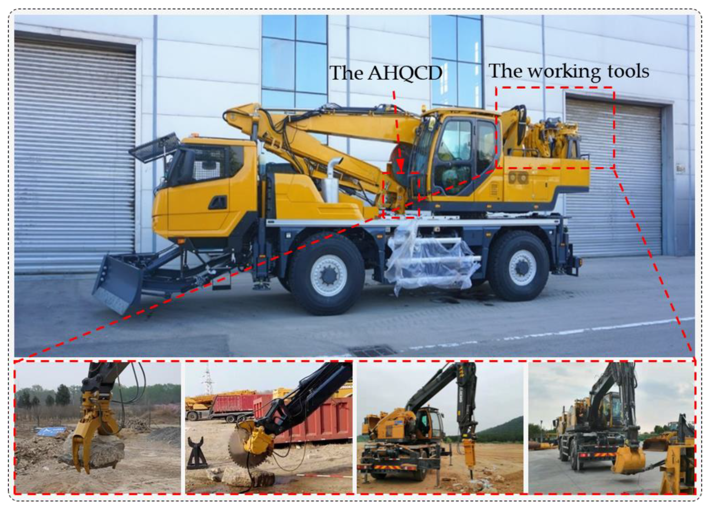
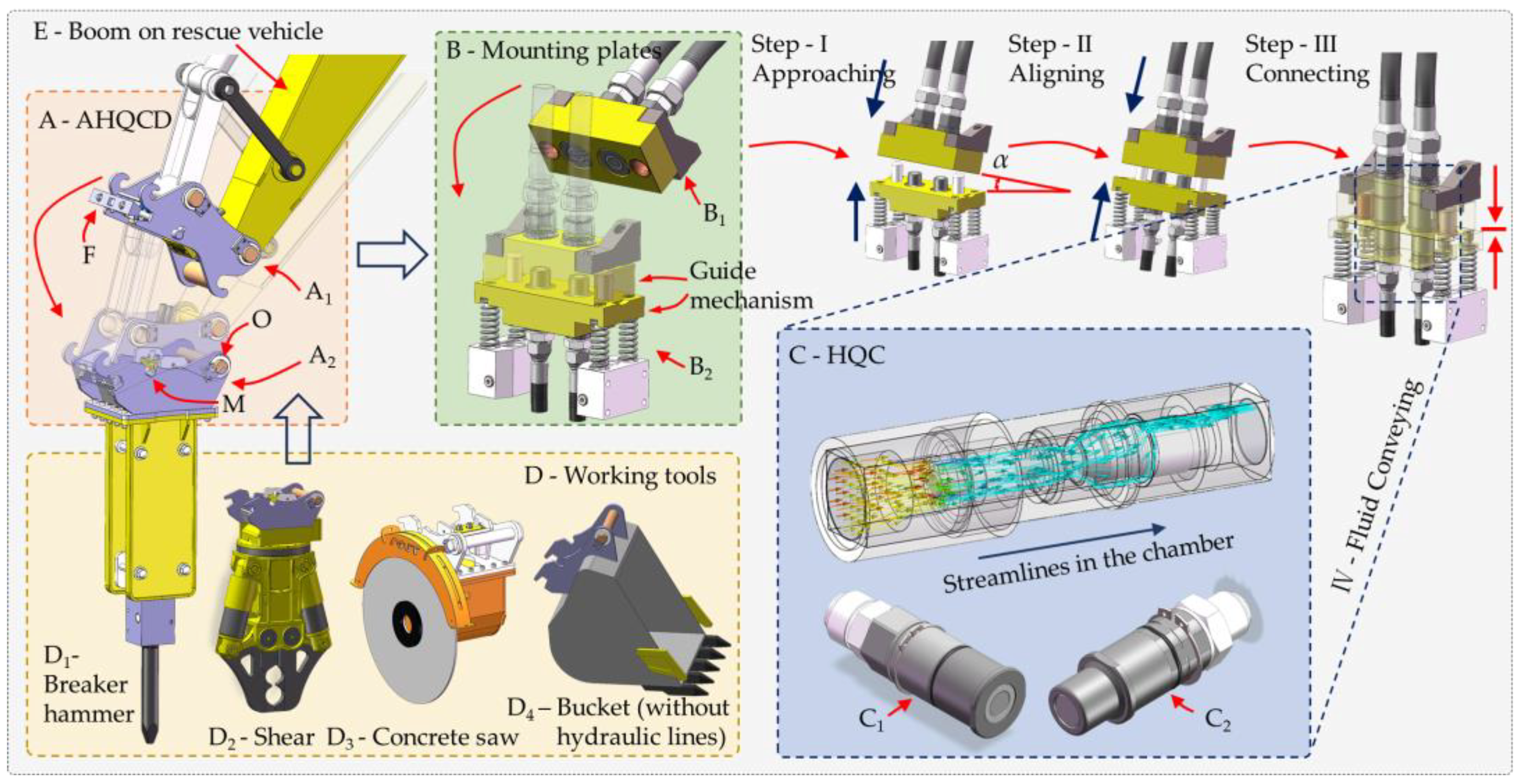
2.1. Introduction to the Automatic Hydraulic Quick Coupling Devices and Hydraulic Quick Coupling System

The hydraulic quick couplings (HQCs) are a critical component of the automatic hydraulic quick coupling device (AHQCD) system on rescue vehicles, designed for quickly docking hydraulic lines and facilitating fluid transport during working tool changes, as shown in Figure 1. The AHQCD consists of two parts: A1, mounted at the boom side, and A2, mounted at the tool side. These parts can be connected at the positioning point M and secured together with a pair of spaced latching axles, O and F, when the boom is moved to hitch with the tool. The HQCs also consist of two parts: the female coupling C1 and the male coupling C2, which are embedded in mounting plates B1 and B2, respectively, with B1 and B2 arranged within A1 and A2. When A1 and A2 are connected together, C1 and C2 are automatically docked through three steps: approaching, aligning, and securely connecting [31].
The detailed internal structure of the HQCs is illustrated in Figure 2. In the disconnected state, the poppet (3) of the female coupling and the poppet (14) of the male coupling are each closed by the supporting forces of springs k1 and k2, respectively, thereby disconnecting and sealing their corresponding hydraulic lines, as illustrated in Figure 2a. In the working state, the two couplings push against each other’s poppets, thereby connecting the oil chambers at both ends, as illustrated in Figure 2b.

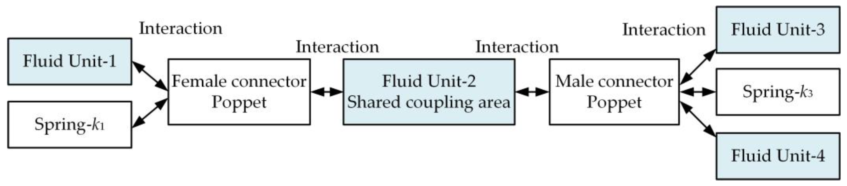
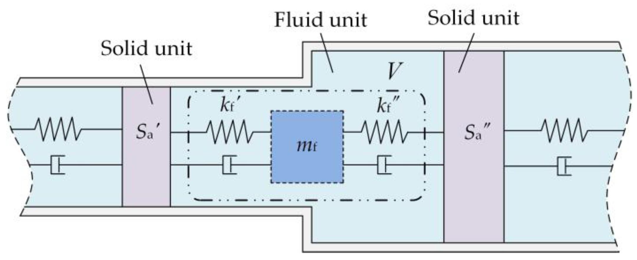
2.2. Dynamic Model of the Hydraulic Quick Couplings Considering Fluid–Structure Interaction

As shown in Figure 2, the HQCs have a very compact configuration with a complex and narrow valve channel. In the working state, as hydraulic fluid flows through this narrow channel, and the internal poppets are accelerated due to pressure pulsations resulting from the strong geometric constraints. This vibration of poppets, in turn, affects the pressure distribution within the flow field, further intensifying the vibration of the poppets. Therefore, fluid–structure interaction between the poppets and the fluid must be considered. Moreover, the fluid–structure interaction at the interface involves the fluid unit, which includes the upstream lines, the shared coupling area, downstream lines, as well as the solid unit, which consists of the two poppets. The influence of the fluid unit on the system’s dynamics primarily involves inertia and compressibility, while the influence of poppets on dynamics includes their inertia and the stiffness of the mechanical spring. The interaction between these units within the coupling system is illustrated in Figure 3.
In Figure 3, Fluid Unit 1 refers to the fluid within the upstream hose and the volume enclosed by the inner chamber of the female poppet. Fluid Unit 3 represents the fluid inside the downstream hose and the volume enclosed between the outer side of the male poppet and the body. Fluid Unit 2 refers to the fluid in the shared coupling chamber. Fluid Unit 4 corresponds to the fluid within the inner chamber of the male poppet, as shown in Figure 2c.
To support theoretical analyses, the dynamic model of the docking system is based on the following assumptions:
(1)
The HQC system is modeled based on the lumped parameter method. It is assumed that the density, stiffness, pressure, and other attribute parameters of each fluid unit in the HQC system are uniformly distributed across the control volume.
(2)
Except for the fluid units and springs, it is assumed that components such as the poppets, body enclosure, and hydraulic hoses are rigid, and their deformation under pressure is neglected.
(3)
Only the axial motion of the poppets is considered, and the forces exerted by the fluid units on the poppets are represented as linear spring forces in the axial direction.
(4)
The damping between the fluids and the poppets is reduced to linear damping in the axial direction.
(5)
Mechanical tolerances and installation errors, such as eccentricity, are neglected.
Building on the aforementioned analysis and assumptions, the dynamic model of the HQCs with connecting hoses is developed, as shown in Figure 4. In this model, m1 and m2 are the masses of the female and male poppets, respectively. k1 and k2 denote the mechanical stiffnesses of the springs associated with the female and male poppets, respectively. c1 and c2 denote the mechanical damping between the poppets and the valve seats. Here, mfi (where i ∈ {1,2,3,4}) represents the mass of each fluid unit, while kf1i, kf2i, kf3i, and kf4i (where i ∈ {1,2}) represent the equivalent stiffness of each fluid unit at a contact boundary with the solid unit, respectively. cf1i, cf2i, cf3i, and cf4i (where i ∈ {1,2}) represent the damping characteristics of each fluid unit. xi (where i ∈ {1,2,3,4,5,6}) denotes the displacement of the equivalent mass blocks of the fluid and solid units.

3. Equations of the Hydraulic Quick Coupling System

3.1. Equivalent Stiffness Model of the Fluid Unit

The concept of equivalent stiffness for the fluid unit in contact with the solid unit was introduced in the previous section. In this subsection, the equivalent stiffness is quantitatively calculated. According to the bulk modulus of elasticity theory for a fluid, as described in references [32,33], we let the bulk modulus of elasticity be Ev, defined as follows:
E v = Δ p Δ V V ,
where V represents the total volume of the fluid unit, ∆V denotes the volume variation, and ∆p is the pressure variation.
The volume change in the fluid unit, determined by the average cross-sectional area Sa and the axial length change ΔL of the fluid unit, is
Δ V = S a Δ L ,
According to the definition of mechanical stiffness, there is
k f = Δ F Δ L = S a Δ p Δ L ,
where ΔF represents the change in load applied to the fluid unit. Based on Equations (1)–(3), the equivalent stiffness of fluid can be expressed by the bulk modulus of elasticity:
k f = E v S a 2 V .
The fluid–structure interaction is concerned with the coupled dynamics of structures in contact with a fluid at their interface. Therefore, the equivalent stiffness of the fluid unit in contact with the solid unit must be calculated separately, based on their contact area, as shown in Figure 5.
Considering Equation (4), the equivalent stiffness kf′ of the fluid unit in contact with the left-side solid unit can be expressed as
k f = E v S a 2 V ,
while the equivalent stiffness kf″ of the fluid unit in contact with the right-side solid unit can be expressed as
k f = E v S a 2 V ,
where Sa′ and Sa″ denote the contact areas between the fluid unit and the solid unit on the left-hand side and the right-hand side, respectively.
As shown in Figure 2, each fluid unit has a relatively complex geometrical feature. To enhance the calculation accuracy of the fluid equivalent stiffness, Fluid Unit 1 is segmented into six parts, while Fluid Unit 2 is divided into four parts based on the structural shape. L1 and L13 represent the upstream and downstream connecting hydraulic lines of the HQCs, respectively. The volumes of the four fluid units are V1, V2, V3, and V4, respectively, as indicated in Equations (7)–(10). The dimensional parameters of each segment of the fluid units are presented in Table 1, while the cross-sectional area parameters of the two poppets are detailed in Table 2.
V 1 = i = 1 6 S a i L i ,
V 2 = S a 8 L 8 ,
V 3 = i = 10 13 S a i L i ,
V 4 = S a 9 L 9 .
Based on Equations (5) and (6), and utilizing the parameters from Table 1 and Table 2, the equivalent stiffness between the fluid unit and the poppet can be calculated under the assumption that the bulk modulus of elasticity Ev for hydraulic oil, which contains a certain amount of air, is 700 MPa. The results are presented in Table 3.

3.2. Free Vibration Equation of the Hydraulic Quick Coupling System

According to the dynamic model of the HQCs with connecting hoses, the equation of free vibration of the docking system is developed as
m x ¨ + k x = 0 ,
where the mass matrix of the docking system is
m = diag ( m f 1 , m 1 , m f 2 , m 2 , m f 3 , m f 4 ) ,
where the stiffness matrix of the system is
k = k f 11 + k f 12 k f 12 0 0 0 0 k f 12 k f 12 + k f 21 + k 1 k f 21 0 0 0 0 k f 21 k f 21 + k f 22 k f 22 0 0 0 0 k f 22 k f 22 + k f 31 + k f 41 + k 2 k f 31 k f 41 0 0 0 k f 31 k f 31 + k f 32 0 0 0 0 k f 41 0 k f 41 + k f 42 ,
the displacement vector x of the system can be expressed as
x = x 1 x 2 x 3 x 4 x 5 x 6 T .

4. Modal Analysis of the Hydraulic Quick Coupling System

4.1. Natural Frequencies and Mode Shapes

Additional physical parameters of the docking system are listed in Table 4, with hydraulic oil containing a certain amount of air at room temperature. Modal analysis of the docking system was conducted by substituting the parameters from Table 3 and Table 4 into the free vibration Equation (11). The natural frequencies and corresponding mode shapes of the docking system are presented in Table 5.
Table 5 shows that the first four natural frequencies of the docking system are below 500 Hz, rendering it susceptible to resonance with the pressure pulsations from the pump, the pressure impulses generated by hydraulic tools, or internal fluid vortices within the system. This can further intensify the fluid pulsations and poppet oscillation, potentially destroying the docking system. Given that the frequency ranges of the aforementioned excitations are typically below 500 Hz, only the first four natural frequencies will be considered in the subsequent analysis of influence factors.
The first-order natural frequency fn1 of the docking system is 88.7 Hz. The corresponding mode shape reveals that when the excitation frequency approaches fn1, resonance occurs, leading to noticeable displacement of both poppets and Fluid Unit 3. Based on the dynamic model described in Figure 4, and Equations (4) and (5), it can be concluded that the equivalent displacement xi of the fluid unit characterizes the magnitude of the pressure fluctuation. The mode shape un1 indicates that the large amplitudes observed in both poppets and Fluid Unit 3 suggest that, under the influence of fluid–structure interaction, the poppets may experience significant vibrations. This results in noticeable pressure pulsations in the downstream hydraulic line, potentially impacting the stability of fluid transmission and reducing the operational efficiency of the working tools.
When the excitation frequency reaches the second natural frequency fn2, the vibration amplitude of both poppets is relatively small, but the upstream pressure pulsation is quite intense. When the excitation frequency reaches the third natural frequency fn3, the vibration amplitude of both poppets increases significantly, while the pressure pulsations in upstream and downstream hydraulic lines become considerably smaller. When the excitation frequency reaches the fourth natural frequency fn4, only the pulsation in Fluid Unit 4 is relatively intense. Furthermore, as indicated in Table 5, the effect of fluid–structure interaction causes the originally independent movements of both poppets to become coupled, which exacerbates the wear of the sealing components.

4.2. Influence of Important Parameters on the Natural Frequency

When keeping the docking configuration and the dimensions of the HQCs unchanged, as constrained by the structure of the AHQCD, the equivalent stiffness of the fluid unit and the mechanical spring stiffness have a significant impact on the natural frequencies and mode shapes of the system. The equivalent stiffness of the fluid unit is directly related to both the working pressure and the air content in the hydraulic oil. Therefore, to identify the variation range of natural frequencies where resonance occurs, it is crucial to assess the impact of these factors—namely, working pressure, air content, and spring stiffness—on the natural frequencies of multiple modes within the system.

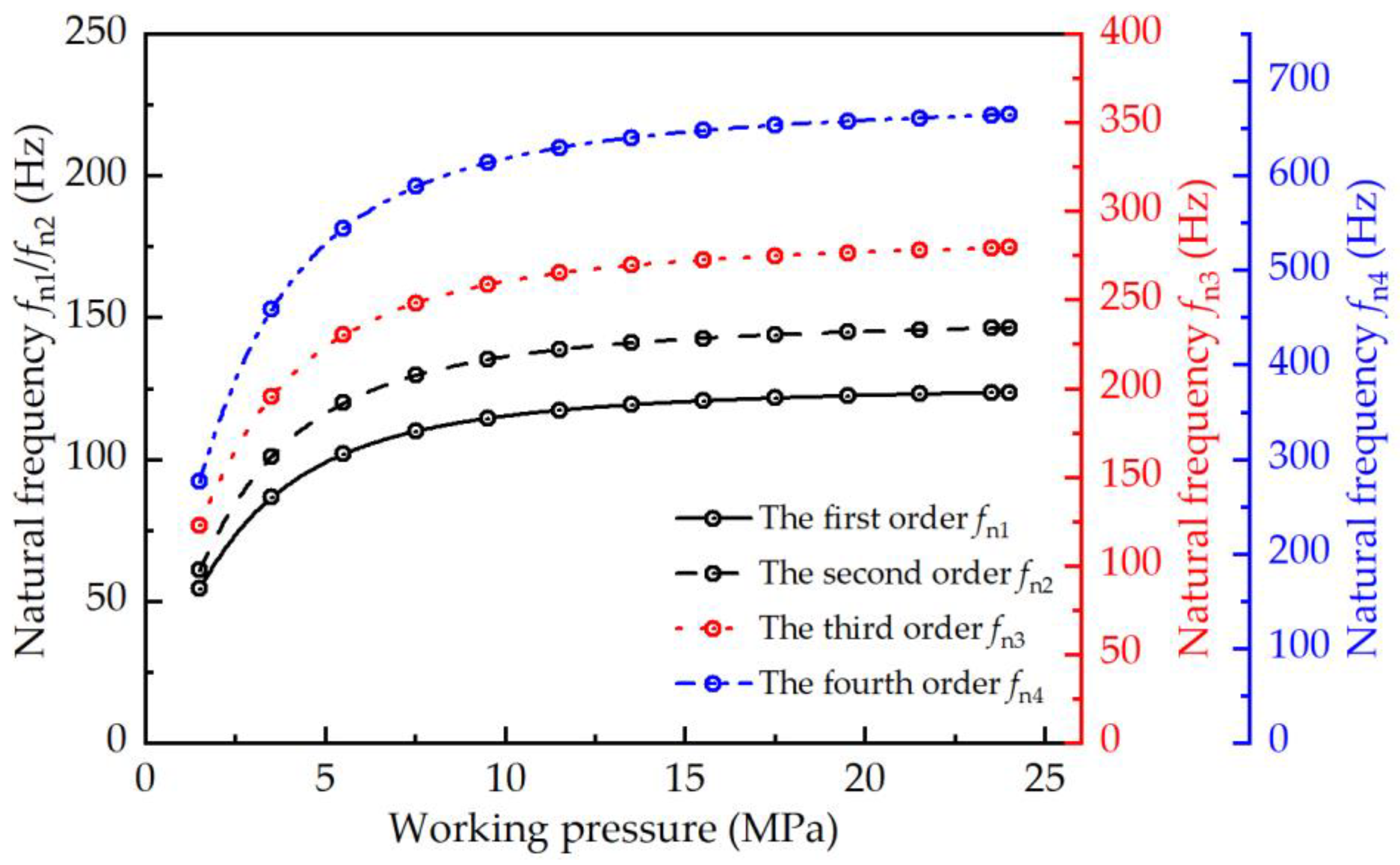
4.2.1. Effect of Working Pressure on the Natural Frequency

Based on the Nykanen model of bulk modulus of elasticity presented in [32], Ev is fundamentally influenced by the pressure and air content for a specified fluid. Therefore, keeping the air content of the oil constant, the effect of working pressure on the first four natural frequencies of the docking system is illustrated in Figure 6.
Figure 6 demonstrates that the first four natural frequencies of the docking system monotonically increase with a rising working pressure. As the working pressure increases, small, entrained air bubbles in the oil (initially undissolved) gradually dissolve into the fluid. This process enhances the bulk modulus of elasticity Ev, thereby reducing the compressibility of fluid. Consequently, the equivalent stiffness of the fluid increases, leading to a rise in the first four natural frequencies with an increasing working pressure.

4.2.2. Effect of Air Content on the Natural Frequency

In rescue scenarios, rescue vehicles frequently switch between hydraulic tools, leading to the repeated disconnection and reconnection of HQCs, as illustrated in Figure 2. This process inevitably introduces a certain amount of air into the hydraulic system. Keeping the working pressure unchanged, the effect of the air content on the first four natural frequencies of the system is obtained, as shown in Figure 7.
It is indicated in Figure 7 that the first four natural frequencies of the system decrease gradually with an increase in air content. When the working pressure remains constant, the bulk modulus of elasticity Ev of the oil decreases with a rising air content, leading to a reduction in the equivalent stiffness of the fluid unit. Meanwhile, the equivalent mass of the fluid unit continuously decreases. However, since the decrease in equivalent mass is much smaller than the decrease in equivalent stiffness, the first four natural frequencies of the system gradually decline as the air content in the fluid increases. This implies that an increase in the number of connection and disconnection cycles will gradually alter the natural frequencies of the docking system, which could negatively impact performance.

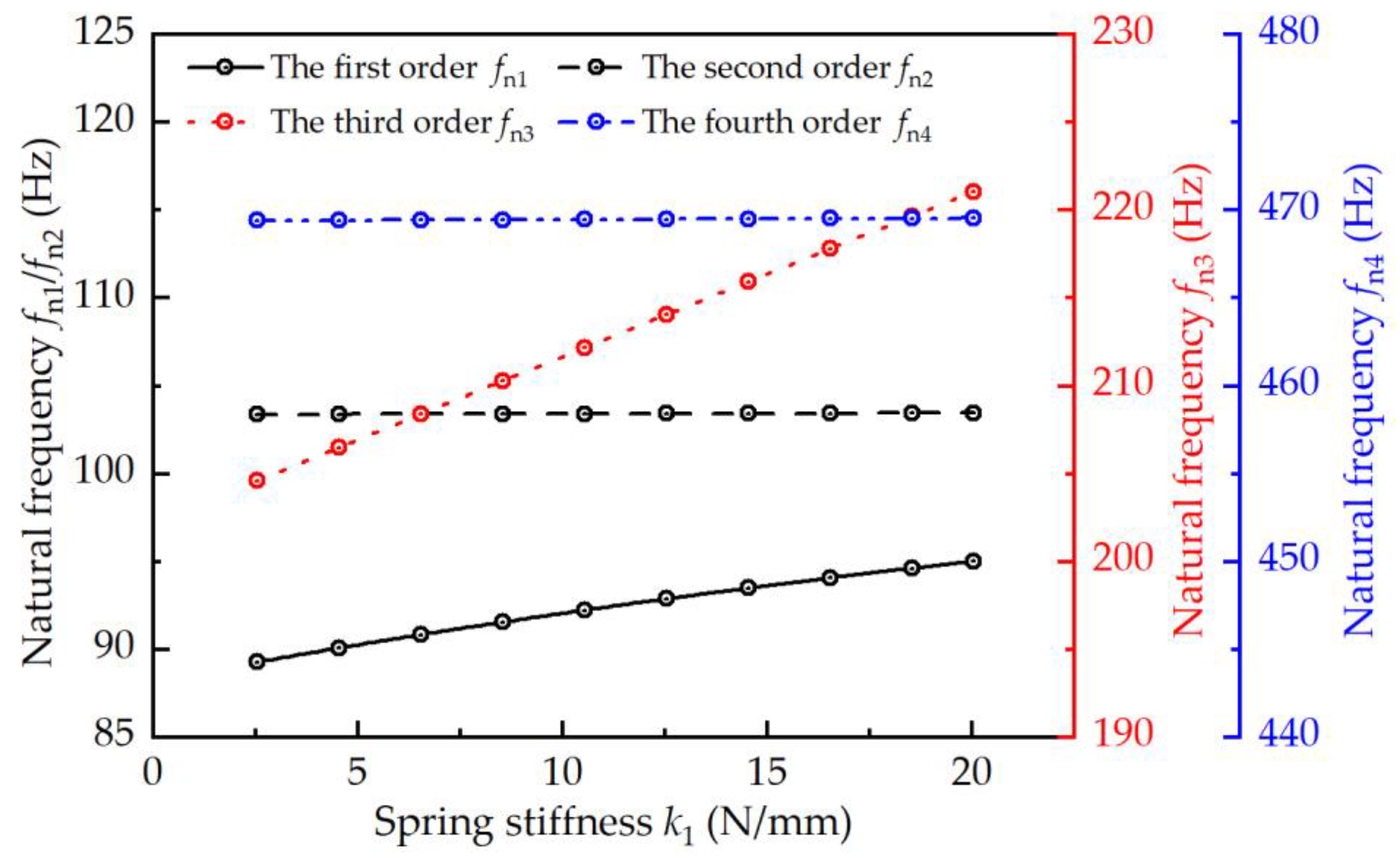
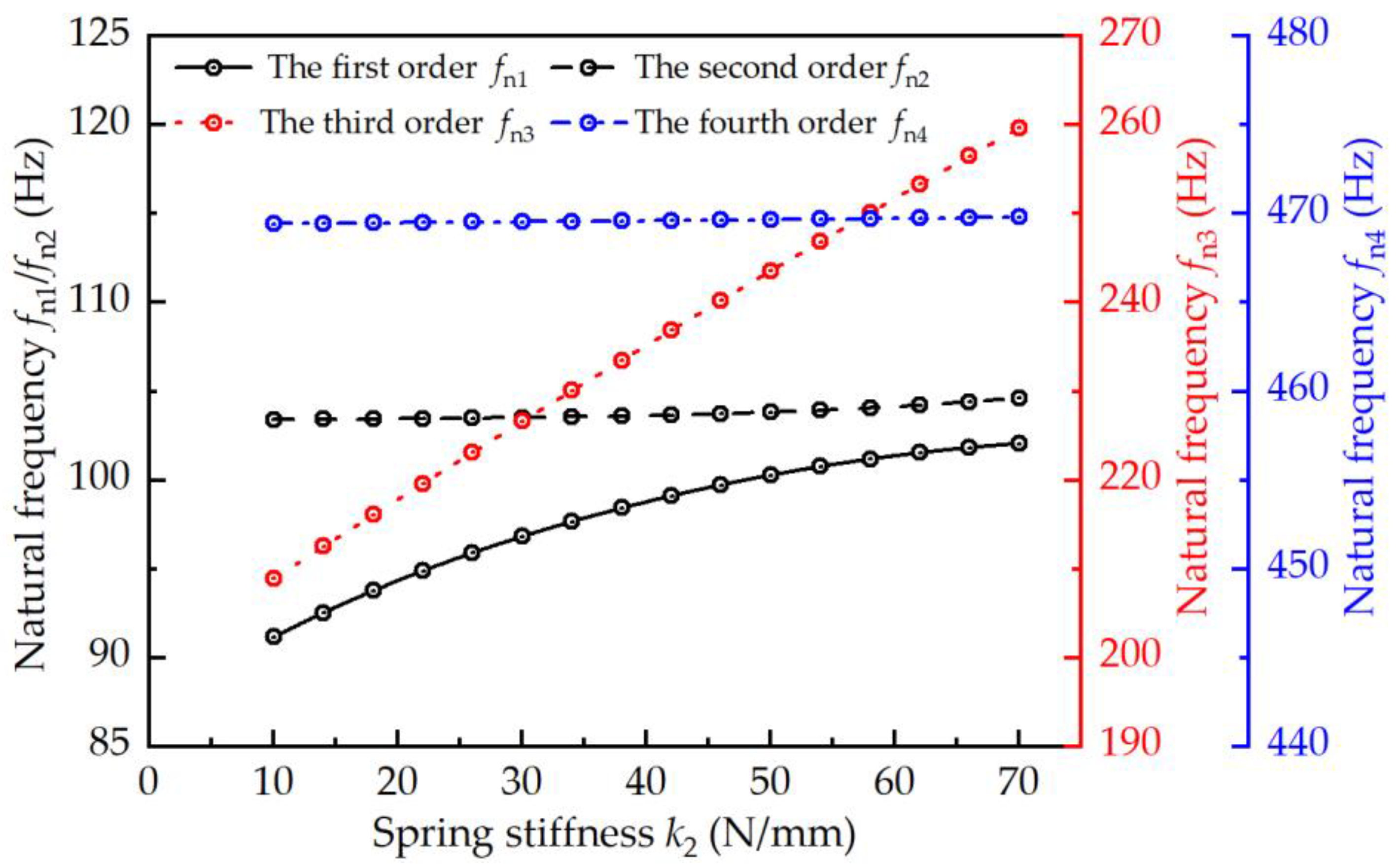
4.2.3. Effect of Spring Stiffness on the Natural Frequency

The stiffness of the springs within two poppets is an important initial design parameter that significantly affects the natural frequencies of the docking system. When the stiffness k1 of the spring in the female poppet ranges from 2.5 to 20 N/mm, and k2 ranges from 10 to 70 N/mm, the variation curves of the first four natural frequencies are as shown in Figure 8 and Figure 9. It can be observed that the sensitivities of each mode’s natural frequency to the spring stiffness are different. The first-order and third-order natural frequencies fn1 and fn3 gradually increases with the rise in spring stiffness k1 and k2, and the growth rate of third-order natural frequency fn3 is significantly larger. In contrast, spring stiffness has little effect on the second-order and fourth-order natural frequencies.

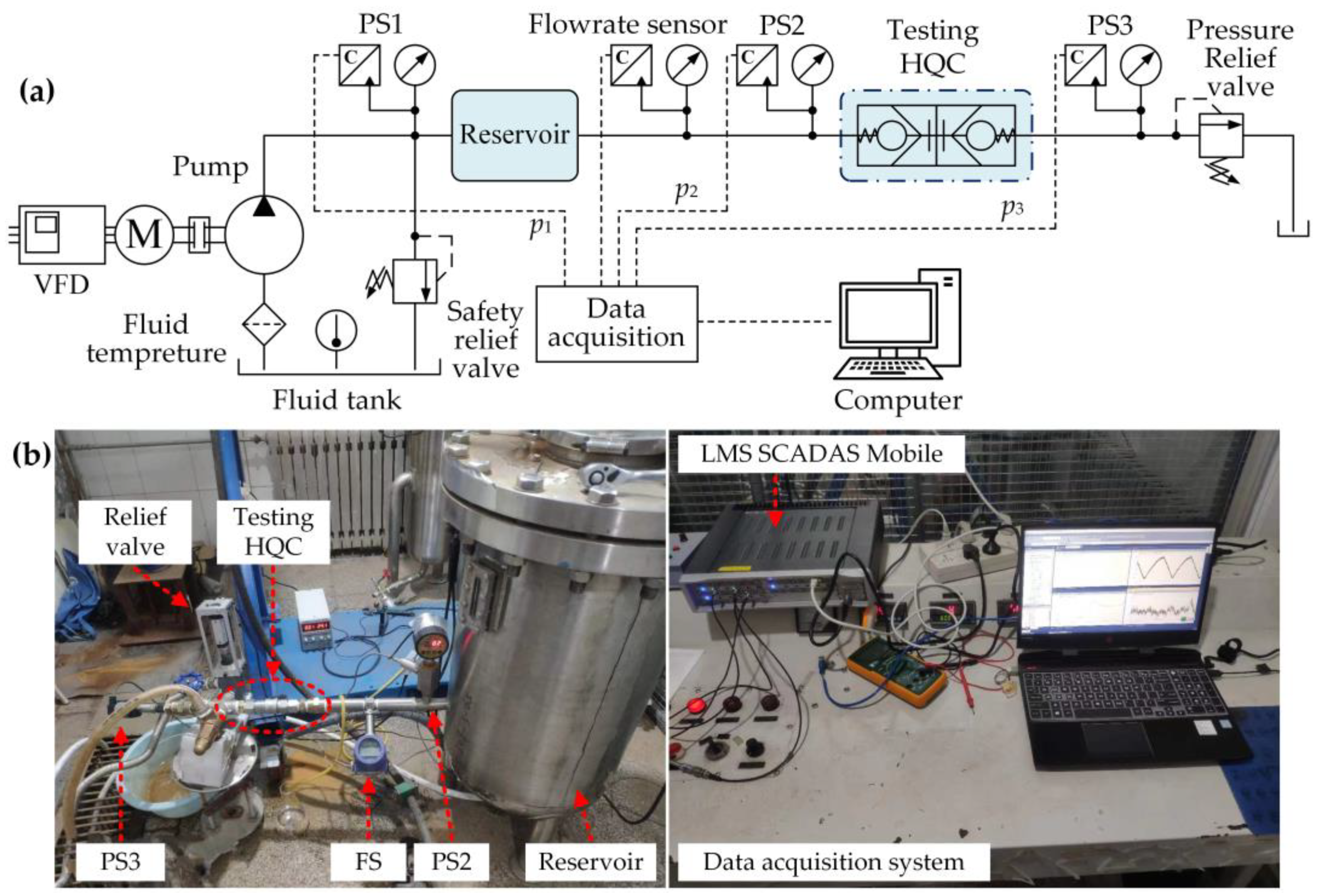
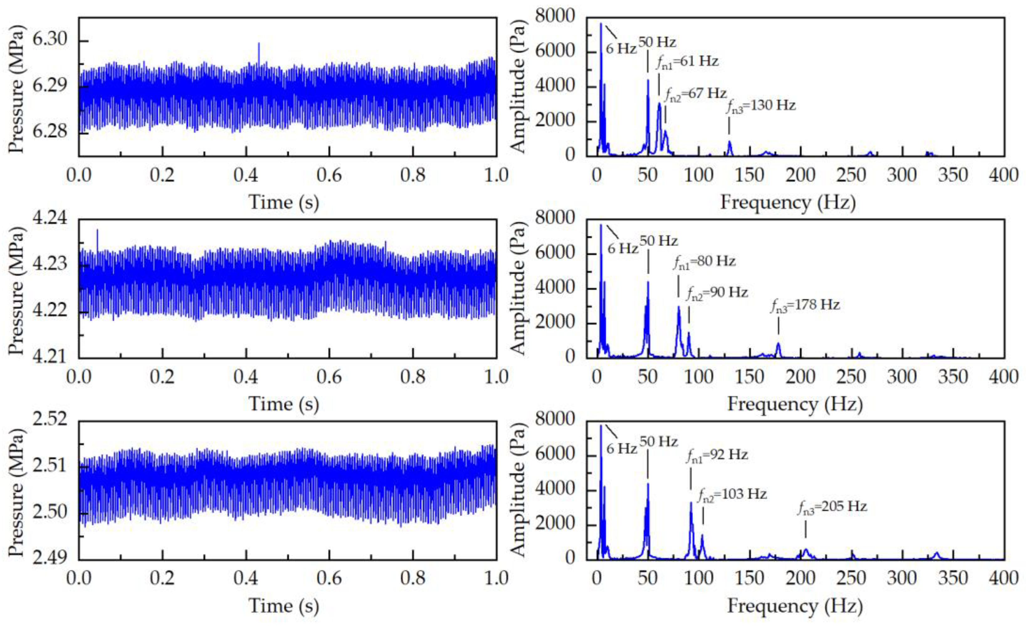
5. Experimental Verification

5.1. Experimental Set-Up

To validate the accuracy of the modal analysis of the docking system, a platform for testing the HQCs with connecting lines was constructed. A schematic of the platform is shown in Figure 10a, while Figure 10b shows a picture of the hydraulic test platform. A three-plunger pump, driven by an electric motor, is used to provide a constant flow of 60 L/min. A pressure relief valve is used to regulate the pressure of the hydraulic system in the range of 2 to 6 MPa. Pressure sensors PS1, PS2, and PS3 are installed to measure the pressure at the pump outlet, upstream line pressure, and output pressure of the testing HQCs, respectively. A reservoir is mounted on the test platform to reduce pressure pulsation and mechanical vibration from the pump, thereby facilitating the measurement of small-amplitude resonance characteristics. It should be noted that, due to constraints of leakage and environmental protection during the docking process, pure water is used as the working fluid in the experiment. The primary differences in physical parameters between pure water and hydraulic oil are presented in Table 6, and all other parameters in the test are set to be identical to those shown in Table 4.

5.2. Experimental Results

The fast Fourier transform was applied to analyze the pressure signal output p3 from the test system in both the time and frequency domains. The amplitude–frequency curves of the pressure signal of the docking system, influenced by fluid self-pulsation excitation, are shown in Figure 11.
It can be observed from Figure 11 that five relatively prominent peaks are present in the frequency domain, while the amplitude at other positions is small. Here, 6 Hz corresponds to the frequency of the three-plunger pump in the experimental system (at a speed of 621 r/min with a gearbox reduction ratio of 4.45), while 50 Hz is the disturbance frequency of the induced current. The peaks labeled fn1, fn2, and fn3 represent the first-order, second-order, and third-order natural frequencies of the docking system, respectively. However, weak resonance amplitudes of other natural frequencies, combined with noise disturbances caused by fluid turbulence in the HQC, complicate frequency spectrum recognition. Consequently, the natural frequencies of other modes cannot currently be identified experimentally.
The first three natural frequencies of the docking system, as determined from the experimental tests, are compared with the theoretical model in Figure 12. As illustrated in Figure 12, the natural frequencies calculated by the proposed theoretical model are basically consistent with the experimental results, and these natural frequencies increase with the increase in pressure p3.
Errors compared with the experimental results can be calculated, as shown in Table 7. The average errors of the first-order fn1, second-order fn2, and third-order fn3 are 2.7%, 5.8%, and 6.7%, respectively. Due to the neglect of elastic deformation, pressure loss, and fluid viscosity in the hydraulic lines in the proposed theoretical model, the experimental data are consistently lower than the theoretical results. However, both the magnitudes and trends exhibit good agreement, thereby verifying the accuracy of the proposed model.

6. Conclusions

When rescue vehicles utilize an AHQCD to connect and operate working tools, as shown in Appendix A, pressure pulsations of multiple frequencies occur in the hydraulic lines. These pulsations may coincide with the natural frequency of the HQCs, potentially resulting in resonance and ultimately leading to failures in fluid transport. To avoid resonance issues, a comprehensive dynamic model of the HQCs with connecting hoses was developed in this study, which can be used to identify the natural frequency of the system. The proposed model was verified through experiments. Additionally, the impacts of working pressure, air content, and spring stiffness on natural frequencies were discussed. The following conclusions can be drawn:
  • Considering the fluid–structure interaction within the HQC system, the dynamic model and 6-DOF equations were developed based on the lumped parameter method. The equivalent stiffness of the fluid units was derived and quantitatively calculated based on the compressibility of the fluid and the configuration of the HQC system.
  • A free vibration analysis of the docking system was conducted. The natural frequencies for each mode, along with their corresponding mode shapes under given conditions, were obtained. The first four natural frequencies below 500 Hz were primarily analyzed, and the characteristics of poppet oscillation and pressure pulsation were thoroughly discussed under resonance conditions based on the corresponding mode shapes. Additionally, it was found that the natural frequencies increase with an increase in working pressure and a decrease in air content, while the spring stiffness only affects the first- and third-order natural frequencies.
  • An experimental test platform for the dynamic model of the HQC system was constructed, and the theoretical model results were compared with experimental data based on the frequency spectrum of the pressure signal. It was found that the error in first-order natural frequency was only 2.7%, while the errors in the second-order and third-order natural frequencies were 5.8% and 6.7%, respectively. These errors may be attributed to the neglect of elastic deformation in hydraulic lines. However, both results exhibit good agreement in terms of magnitudes and trends, confirming the accuracy of the proposed model.
The limitations of this study include its inability to account for the time-varying equivalent stiffness of the fluid due to pressure pulsations. More accurate analytical models will be adopted to describe the fluid–structure interaction in complex hydraulic pipelines. The added coupled coefficients of the fluids will be determined to further investigate the dynamic behaviors in the docking system. Future research will consider the effects of fluid pressure pulsations in the HQC system and develop a comprehensive parametric vibration model based on the time-varying fluid stiffness, which may lead to main resonances and combined resonances that seriously deteriorate the dynamic behavior of the system. Further investigation will optimize the design parameters under various working conditions to improve the stability of fluid transmission.

Author Contributions

Conceptualization, Z.Z.; methodology, F.M.; software, Y.L.; formal analysis, Y.L.; data curation, C.J.; writing—original draft preparation, Y.L.; writing—review and editing, S.W. and X.G.; supervision, F.M.; funding acquisition, F.M. All authors have read and agreed to the published version of the manuscript.

Funding

This research was funded by the National Key Research and Development Program of China, grant numbers 2016YFC0802905 and 2018YFC0810501.

Data Availability Statement

Data will be made available on request.

Conflicts of Interest

The authors declare no conflicts of interest.

Appendix A

The HQC system developed in our previous work was applied in a heavy-duty rescue vehicle XCMG 240WQ, which is designed for geohazards.
Figure A1. Images of the heavy-duty rescue vehicle and its testing operation.
Actuators 13 00515 g0a1

References

  1. Dong, B.; Zhang, Z.; Xu, L. Research Status and Development Trend of Intelligent Emergency Rescue Equipment. J. Mech. Eng. 2020, 56, 1–25. [Google Scholar] [CrossRef]
  2. Wang, Z. A preliminary report on the Great Wenchuan Earthquake. Earthq. Eng. Eng. Vib. 2008, 7, 225–234. [Google Scholar] [CrossRef]
  3. Chen, J.; Guan, P.; Zhang, Y. Key technology analysis of full-automatic quick coupling device of rescue vehicle. Mech. Res. Appl. 2020, 33, 238–242. [Google Scholar] [CrossRef]
  4. Zhong, J.; Jiang, W.; Zhang, Q.; Zhang, W. Design and Simulation of a Seven-Degree-of-Freedom Hydraulic Robot Arm. Actuators 2023, 12, 362. [Google Scholar] [CrossRef]
  5. Quick Coupling Systems. Available online: https://www.liebherr.com/en/usa/products/attachments/quick-couplers/quick-couplers.html (accessed on 31 October 2023).
  6. Automatic Quick Coupler System for Excavators. Available online: https://www.oilquick.com/en/products/oq/ (accessed on 4 May 2024).
  7. CW-70 Quick Coupler the Fast Connection. Available online: https://www.cat.com/zh_CN/products/new/attachments/couplers-excavator.html (accessed on 10 May 2024).
  8. ADX Auto-Dock Couplings. Available online: https://www.cejn.com/ (accessed on 12 May 2024).
  9. PC490HRD-11 High Reach Demolition machine with K100 Quick Boom Change System. Available online: https://www.komatsu.eu/en/campaign/k100-quick-boom-change-system (accessed on 1 June 2021).
  10. Tang, Z.; Yun, C. Quick action coupling technology in full-automatic quick coupling device: A review. J. Zhejiang Univ. Eng. Sci. 2017, 51, 461–470. [Google Scholar] [CrossRef]
  11. Tang, Z.; Yun, C. Precise docking technology in full-automatic quick hitch coupling device. J. Beijing Univ. Aeronaut. Astronaut. 2017, 43, 1859–1872. Available online: https://html.rhhz.net/BJHKHTDXXBZRB/20170918.htm (accessed on 8 December 2024).
  12. Yang, Q.; Dong, R.; Luo, X.; Lv, Q. Vibration Characteristics of Hydraulic Pipe Network Under Multi-Source Excitation. Chin. Hydraul. Pneumat. 2021, 45, 163–170. [Google Scholar] [CrossRef]
  13. Jiang, H.; Zhang, J.; Zhou, X.; Li, W.; Ma, J.; Qiu, Y. Analytic expression and series expansion of pulsation pressures of aviation hydraulic pumps. J. Aerospace Power 2023, 38, 197–205. [Google Scholar] [CrossRef]
  14. Geng, X.; Ma, F.; Ma, W.; Zhou, Z.; Liu, Y. Experimental on Impact Powerless of Heavy Hydraulic Rock Drill with Double Damper System. J. Vib. Meas. Diagn. 2018, 38, 1051–1087. [Google Scholar] [CrossRef]
  15. Su, J. Characteristics analysis of breaker hydraulic system of hydraulic vibration impact robot. Hydraul. Pneum. Seals 2022, 42, 29–33. [Google Scholar] [CrossRef]
  16. Misra, A.; Behdinan, K.; Cleghorn, W.L. Self-excited vibration of a control valve due to fluid-structure interaction. J. Fluids Struct. 2002, 16, 649–665. [Google Scholar] [CrossRef]
  17. Su, Y.; He, J.; Zhang, M.; Gong, W. Vibration characteristics of a rocket engine flow pipeline under external excitation. J. Vib. Shock 2024, 43, 60–70. [Google Scholar] [CrossRef]
  18. Li, H.; Gu, J.; Li, J.; Sun, Z.; Sun, K.; Liu, X.; Wang, X.; Zhang, B.; Wang, X.; Ma, H. Dynamics modeling and validation of L-shaped pipeline in aero-engine subjected to base random vibration excitation and fluid pressure pulsation excitation loads. Acta Aeronaut. Astronaut. Sin. 2024, 45, 229375. Available online: https://link.cnki.net/urlid/11.1929.V.20240204.0851.004 (accessed on 8 December 2024).
  19. Persson, B.N.J.; Yang, C. Theory of the leak-rate of seals. J. Phys. Condens. Matter 2008, 20, 315011. [Google Scholar] [CrossRef]
  20. Wang, Q.; Wang, Z.; Wu, W.; Yu, B.; Zhang, P. Effects of Vibration and Shock on the Transient Performance of the Mechanical Seal. Tribology 2024, 44, 1–13. [Google Scholar] [CrossRef]
  21. Pan, Y.; Cai, T.; Ma, F.; Qiu, L.; Gao, L. Device Configuration and Frequency Characteristics of Self-resonating Water Jet. J. Mech. Eng. 2020, 56, 207–213. [Google Scholar] [CrossRef]
  22. Cao, Y.; Guo, X.; Ma, H.; Ge, H.; Li, H.; Lin, J.; Jia, D.; Wang, B.; Ma, Y. Dynamic modelling and natural characteristics analysis of fluid conveying pipeline with connecting hose. Mech. Syst. Sig. Process. 2023, 193, 110244. [Google Scholar] [CrossRef]
  23. Ding, H.; Tan, X.; Dowell, E.H. Natural frequencies of a super-critical transporting Timoshenko beam. Eur. J. Mech. A Solids 2017, 66, 79–93. [Google Scholar] [CrossRef]
  24. Yuan, X.; Wang, C.; Zhao, S.; Zhang, L. Analysis of Free Vibration of Adaptive Head Jet System of Fire Water Monitor. J. Mech. Eng. 2020, 56, 256–262. [Google Scholar] [CrossRef]
  25. Yuan, X.; Zhu, X.; Wang, C.; Zhang, L.; Zhu, Y. Natural Frequency Sensitivity Analysis of Fire-Fighting Jet System with Adaptive Gun Head. Processes 2019, 7, 808. [Google Scholar] [CrossRef]
  26. Liao, M.; Zheng, Y.; Gao, Z.; Song, W. Fluid-structure coupling modelling and parameter optimization of a direct-acting relief valve for underwater application. Nonlinear Dyn. 2021, 105, 2935–2958. [Google Scholar] [CrossRef]
  27. Kang, J.; Yuan, Z.; Wang, J. Numerical study on hydrodynamic oscillation and forced vibration in front stage of pressure servo valve. J. Vib. Shock 2021, 40, 120–128. [Google Scholar] [CrossRef]
  28. Chris, B.; Abraham, E. Analysis of flow-induced instability in a redesigned steam control valve. Appl. Therm. Eng. 2015, 83, 40–47. [Google Scholar] [CrossRef]
  29. Buscarino, A.; Famoso, C.; Fortuna, L.; La Spina, G. Nonlinear Jump Resonance: Recent Trends from Analysis to Electronic Circuits Implementations. IEEE Trans. Circuits Syst. II Express Briefs 2023, 71, 1727–1732. [Google Scholar] [CrossRef]
  30. Wu, W.; Tian, G.; Hao, Q. Analysis and optimization of abnormal opening of main port of relief valve under alternating pressure. J. Huazhong Univ. Sci. Technol. (Nat. Sci. Ed.) 2018, 46, 78–83. [Google Scholar] [CrossRef]
  31. Ma, F.; Jin, C.; Liu, Y.; Shen, Y.; Gao, L. Multi-Degree-of-Freedom Automatic Center-Adjusting Device, Hydraulic Quick-Coupling Device, and Rescue Equipment. U.S. Patent No. US 11,035,093 B2, 15 June 2021. [Google Scholar]
  32. Wei, C.; Zhou, J.; Yuan, S. Comparison of Steady and Dynamic Models for the Bulk Modulus of Hydraulic Oils. Acta Armamentarii 2015, 36, 1153–1159. [Google Scholar] [CrossRef]
  33. Clayton, T.C.; Donald, F.E.; Barbara, C.W.; John, A.R. Engineering Fluid Mechanics, 9th ed.; John Wily & Sons, Inc.: New York, NY, USA, 2009. [Google Scholar]
Figure 1. Schematic of the operational process of the AHQCD.
Actuators 13 00515 g001
Figure 2. The detailed schematic of internal structure of the HQCs. 1, 6—Female body; 2, 12—Mounting plate; 3—Female poppet; 4—Inner sleeve; 5—Central stem; 7, 17—Circlip; 8, 9, 10, 11—Sealing system; 13, 16—Male body; 14—Male poppet; 15—Guide; 18, 21—Connector adaptors; 19, 22—Hose assembly; 20—Fixed plate.
Actuators 13 00515 g002
Figure 3. The coupling between the fluid and the solid within the HQCs. The blue-shaded boxes indicate the fluid units.
Actuators 13 00515 g003
Figure 4. Dynamic model of the HQCs with connecting hoses.
Actuators 13 00515 g004
Figure 5. Schematic of equivalent stiffness for the fluid unit in contact with the solid unit.
Actuators 13 00515 g005
Figure 6. Variation curves of the first four natural frequencies at different working pressures.
Actuators 13 00515 g006
Figure 7. Changes in the first four natural frequencies with different air contents.
Actuators 13 00515 g007
Figure 8. Changes in the first four natural frequencies with different stiffnesses of female springs.
Actuators 13 00515 g008
Figure 9. Variation curves of the first four natural frequencies with different stiffnesses of male springs.
Actuators 13 00515 g009
Figure 10. Experimental test system: (a) schematic of the experimental system, (b) picture of the hydraulic test platform.
Actuators 13 00515 g010
Figure 11. The experimental time series of pressure p3 and amplitude–frequency characteristic curves.
Actuators 13 00515 g011
Figure 12. Changing curves of natural frequencies of the docking system at different pressures: (a) the first order fn1, (b) the second order fn2, (c) the third order fn3.
Actuators 13 00515 g012
Table 1. Dimensional parameters of each segment of the fluid units.
Fluid UnitSegmentAxial Length of the Fluid Domain Li/(mm)Average Area of Flow Cross-Section Sai/(mm2)
Fluid Unit 1I–IIL1 = 1500Sa1 = 401.1
II–IIIL2 = 55.5Sa2 = 201.1
III–IVL3 = 7.5Sa3 = 471.4
IV–VL4 = 13.5Sa4 = 283.5
V–VIL5 = 8Sa5 = 57.7
VI–IL6 = 34.5Sa6 = 99.5
Fluid Unit 2II–VIIL8 = 26.1Sa8 = 171.1
Fluid Unit 3VII–VIIIL10 = 26.5Sa10 = 35.3
VIII–IXL11 = 5.2Sa11 = 283.5
IX–XL12 = 40Sa12 = 153.9
X–XIL13 = 1500Sa13 = 201.1
Fluid Unit 4III–VIIIL9 = 36.75Sa9 = 63.6
Table 2. Cross-sectional parameters of the two poppets.
PoppetLocation of the End Face 1End Face Area Api/mm2
Female poppetVIAp11 = 68.33
IAp12 = 37.70
Male poppetVIIAp21 = 168.73
IIIAp22 = 63.62
1 Location of the end face of two poppets labeled in Figure 2.
Table 3. Equivalent stiffness from the interaction between the fluid unit and the poppet.
Fluid UnitEquivalent Stiffness (N/mm)Value
Fluid Unit 1kf11199.7
kf127.6
Fluid Unit 2kf211761.8
kf228460.1
Fluid Unit 3kf3162.2
kf3288.4
Fluid Unit 4kf418.8
kf428.8
Table 4. Physical parameters of the docking system.
Parameter NameValue
Mass of female poppet m1 (kg)0.029
Mass of male poppet m3 (kg)0.022
Mass of Fluid Unit 1 mf1 (kg)0.4934
Mass of Fluid Unit 2 mf2 (kg)0.0041
Mass of Fluid Unit 3 mf3 (kg)0.2802
Mass of Fluid Unit 4 mf4 (kg)0.0020
Stiffness of the spring for female poppet k1 (N/mm)1.23
Stiffness of the spring for male poppet k2 (N/mm)3.85
Density of hydraulic oil ρ (kg·m−3)875
Initial gas content of hydraulic oil α (%)5
Bulk elastic modulus of hydraulic oil Ev (MPa)700
Temperature T (°C)25
Table 5. Natural frequencies and modal shapes of the HQC system.
OrderFirst-OrderSecond-OrderThird-OrderFourth-OrderFifth-OrderSixth-Order
Natural frequency
fni/Hz
fn1fn2fn3fn4fn5fn6
88.7103.4203.4469.416918505
Modal shapes uniFluid Unit 10.14081−0.012700.00010
Female poppet1−0.11461−0.0239−0.8379−0.0217
Fluid Unit 20.9993−0.11870.9782−0.02060.71531
Male poppet0.9990−0.11950.9729−0.01981−0.1558
Fluid Unit 30.9786−0.2296−0.19730.0005−0.00200
Fluid Unit 40.5182−0.06280.60021−0.04130.0002
Table 6. The primary different physical parameters of pure water with hydraulic oil.
ParameterValue
Bulk modulus of elasticity Ev (MPa)220
Viscosity μ (N·s/m2)1 × 10−3
Mass density ρ (kg·m−3)998
Table 7. Comparison of experimental data with theoretical values.
OrderPressure ConditionsExperimental Data (Hz)Proposed Model (Hz)Error (%)
fn12.516162.52.4Avg. 2.7
4.238082.22.8
6.299294.72.9
fn22.516770.04.5Avg. 5.8
4.239094.85.3
6.29103110.97.6
fn32.51130136.24.8Avg. 6.7
4.23178190.46.9
6.29205222.48.4
Disclaimer/Publisher’s Note: The statements, opinions and data contained in all publications are solely those of the individual author(s) and contributor(s) and not of MDPI and/or the editor(s). MDPI and/or the editor(s) disclaim responsibility for any injury to people or property resulting from any ideas, methods, instructions or products referred to in the content.

