Article

Fuzzy Failure Modes, Effect and Criticality Analysis on Electromechanical Actuators

1
Department of Integrated Technology and Control Engineering, School of Aeronautics, Northwestern Polytechnical University, Xi’an 710072, China
2
National Key Laboratory of Aircraft Design, Xi’an 710072, China
3
Chengdu Kaitian Electronics Co., Ltd., Chengdu 610091, China
*
Author to whom correspondence should be addressed.
Actuators 2024, 13(12), 510; https://doi.org/10.3390/act13120510
Submission received: 30 October 2024 / Revised: 5 December 2024 / Accepted: 6 December 2024 / Published: 9 December 2024
(This article belongs to the Section Aerospace Actuators)

Abstract

:
The electromechanical servo is the preferred aviation servo actuator system now. EMA (electromechanical actuators), especially EMA of airplanes, will inevitably occur a variety of faults. FMECA (Failure Modes, Effect and Criticality Analysis) is commonly used to analyze the failure mode of the product. However, traditional FMECA is easily affected by subjective factors, and previous studies on FMECA have not focused on the EMA of airplanes. Therefore, this paper was carried out to provide a method of EMA failure modes analysis to find out the most vulnerable part of EMA. Firstly, we analyzed the PMSM using traditional FMECA to obtain a preliminary result for further examination. Then, we used fuzzy comprehensive evaluation to quantify qualitative evaluation indicators and build a fuzzy FMECA model based on fuzzy comprehensive evaluation, which can directly obtain the risk ranking of each failure mode. At the same time, the model was used on PMSM, which is an important part of EMA, to give an example of using this method. Finally, two results were compared to verify the accuracy of the improvement method. The main contribution of the article was to propose a model that can rank the risk levels of all components in EMA on airplanes based on fuzzy FMECA.

1. Introduction

Nowadays, with the booming development of new energy technologies, transportation vehicles represented by airplanes and cars are gradually moving towards electrification, and even many forms of industrial equipment are changing from hydraulic systems to electromechanical actuators. Typical examples are electric vehicles, MEA (More Electric Aircraft), and AEA (All Electric Aircraft) [1,2,3]. The electrification of automobiles and airplanes inevitably means the electrification of core components such as engines, braking systems, servo systems, and other important systems. Taking airplanes as an example, servo systems, as key components on airplanes, need to develop towards high output, high power, high prior and posterior reliability, and short response time [4]. Therefore, new EMA (electromechanical actuators) are gradually replacing traditional hydraulic actuators as actuators for aircraft rudders [5,6]. Electric actuators are divided into two categories: EMA (electromechanical actuators) and EHA (electro-hydraulic actuators) [7,8]. Compared with EHA, EMA does not have a hydraulic mechanism and has the characteristics of a simple structure, high power density, and easy maintenance [9,10]. Therefore, EMA is widely used in driving devices such as landing gear retraction, aircraft wing deployment, servo steering, and electric braking for EMA and AEA [11].
As the focus of our study, EMA on the aircraft operate in harsh environments such as low temperatures and high pressures for a long time, and they have complex systems and diverse operations. Therefore, it is inevitable that short-term or permanent failures will occur, and there are various types of failures. [12]. It was necessary to conduct a comprehensive analysis on the failure modes for the purpose of conducting a study of PHM (Prognostics Health Management) on EMA. FMECA (Failure Modes, Effect and Criticality Analysis) is the most commonly used failure mode analysis method at present [13]. It is summarized in engineering practice, and it is an analysis technology based on failure modes and aimed at fault impact. FMECA is an analysis technology that analyzes every possible failure mode of products, determines the impact of the failure mode on the product and the upper product, and classifies each failure mode according to the severity of its impact, occurrence probability, and fault hazard degree [14].
People have done enough research on FMECA and its improvements, including many industries. Chao Liu et al. [15] combined FMECA with FFTA (Fuzzy Fault Tree Analysis) in order to propose a method of subsea manifold system analysis. Gizem Elidolu et al. [16] used traditional FMECA and rule-based fuzzy logic technique with Gaussian membership functions to perform a risk assessment specific to hazardous cargoes with special requirements on ships. Jing Tian et al. [17] also used FMECA and FTA (Fault Tree Analysis) to find the weak links in the circuit board. Awais Yousaf et al. [18] extended an existing cyber risk assessment approach called FMECA-ATT&CK based on FMECA and the MITRE ATT&CK framework to assess cyber risks related to systems with artificial intelligence components in cyber-enabled autonomous ships. Chao Huang et al. [19] conducted a comprehensive assessment of fault severity, fault occurrence probability, and fault detection difficulty on the CRTS II slab track structure and the modular assembled track structure with built-in position retention by adopting the fuzzy FMECA method. Yangyang Zhang et al. [20] proposed an improved FMECA method based on an adaptive weighted information fusion model, on the basis of the fuzzy FMECA method. By constructing an initial weight judgment support matrix, the weights of different information sources were determined, and the weight results of each influence factor were obtained. Sezer Sukru Ilke et al. [21] adopted a holistic risk assessment incorporating FMECA and Dempster–Shafer (D–S) evidence theory to systematically analyze ship recycling hazards and reveal potential consequences to the marine environment. Patricio F. Castro et al. [22] used FMECA documentation establishing the failure modes through expert knowledge and built a novel approach for diagnosing failures within a turbogenerator mineral lube oil system. Zhou Qingji et al. [23] proposed a fuzzy FMECA method to study the safety assessment of the hydraulic submersible pump system (HSPS). Andrés A. Zúñiga et al. [24] used fuzzy FMECA for reliability analysis of cyber-power grid systems.
However, due to the limitation that traditional FMECA is susceptible to subjective factors and the requirement that the failure of EMA on airplanes should be better studied, this paper improved the traditional FMECA, applied fuzzy comprehensive evaluation to quantify the qualitative evaluation index, and built a fuzzy FMECA model based on fuzzy comprehensive evaluation, which can directly obtain the risk ranking of each failure mode. Fuzzy theory is based on fuzzy sets, and its basic spirit is to accept the fact that fuzzy phenomena exist, with the research goal of dealing with vague and uncertain concepts, and actively quantifying them into information that computers can process. It does not advocate using complex mathematical analysis or models to solve models. The fuzzy model can help a lot in mechanical systems [25,26].
Firstly, the composition and working principle of EMA were analyzed. Therefore, the most important part of EMA was picked and analyzed by the traditional FMECA. Finally, the fuzzy FMECA was used for further analysis of the key components.
The main contributions of this paper are:
  • In view of the shortcomings of traditional FMECA, fuzzy FMECA for EMA was proposed. We analyzed the PMSM of EMA using traditional FMECA and then built a fuzzy FMECA model for EMA based on the comments of industry experts and experimental experience, including the fuzzy comprehensive evaluation matrix and the method of fuzzy comprehensive evaluation.
  • PMSM (Permanent Magnet Synchronous Motor) was further analyzed as the key component of EMA to give an example of using fuzzy FMECA on EMA. The result came out that the interturn short circuit fault is the highest risk of failure in PMSM, and the ranking of faults were also presented. Finally, the results of fuzzy FMECA and traditional FMECA were compared to prove the correctness and progressiveness of the method.

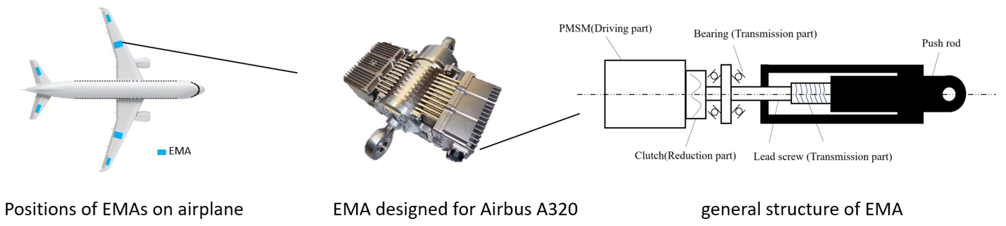
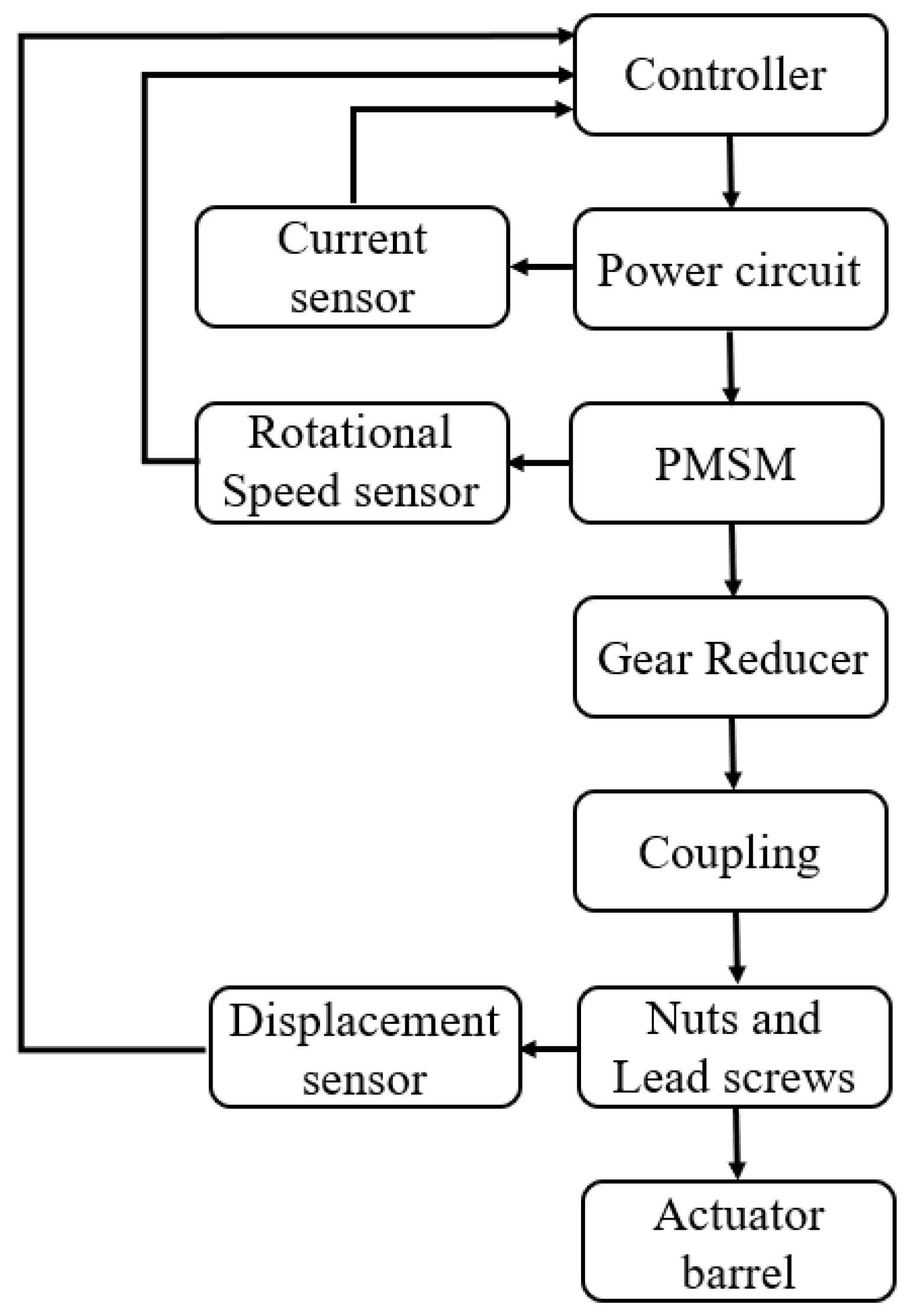
2. Structure and Working Principle of EMA

EMA is generally composed of a controller and a power drive module, a PMSM, a reducer, a coupling, a PRSM (Planetary Roller Screw Mechanism), and a sensor composition. Figure 1 shows a general structure of EMA.

2.1. Driving Part

The driving devices of EMA mainly include a controller, a power driving module, and a driving motor, as shown in the Figure 2. The controller receives feedback from the displacement sensor, compares it with the given value, calculates the control quantity using the corresponding control algorithm, and drives the circuit to control the motor operation. Permanent Magnet Synchronous Motor is a typical type of synchronous motor.

2.2. Reduction Part

The reducer, the red part in Figure 1, is a high-precision gear transmission device that works by transmitting gears between gear transmission systems to achieve the matching of speed and torque in the gear transmission system. Its function is to reduce the speed and increase the torque.

2.3. Transmission Part

On airplanes, the main function of EMA is to lift or close the rudder. As shown in the green part of Figure 1, the transmission part of EMA consists of a lead screw, a coupling, and an actuator barrel. Lead screws are used to convert the rotating motion of the motor into linear motion.

2.4. Feedback Part

The yellow part of Figure 1 shows that the feedback part includes current sensors, speed sensors, and displacement sensors. They convert current signals, speed signals, and position signals into electrical signals and provide feedback to the system, forming a closed-loop control of the electromechanical drive system to ensure its normal operation.

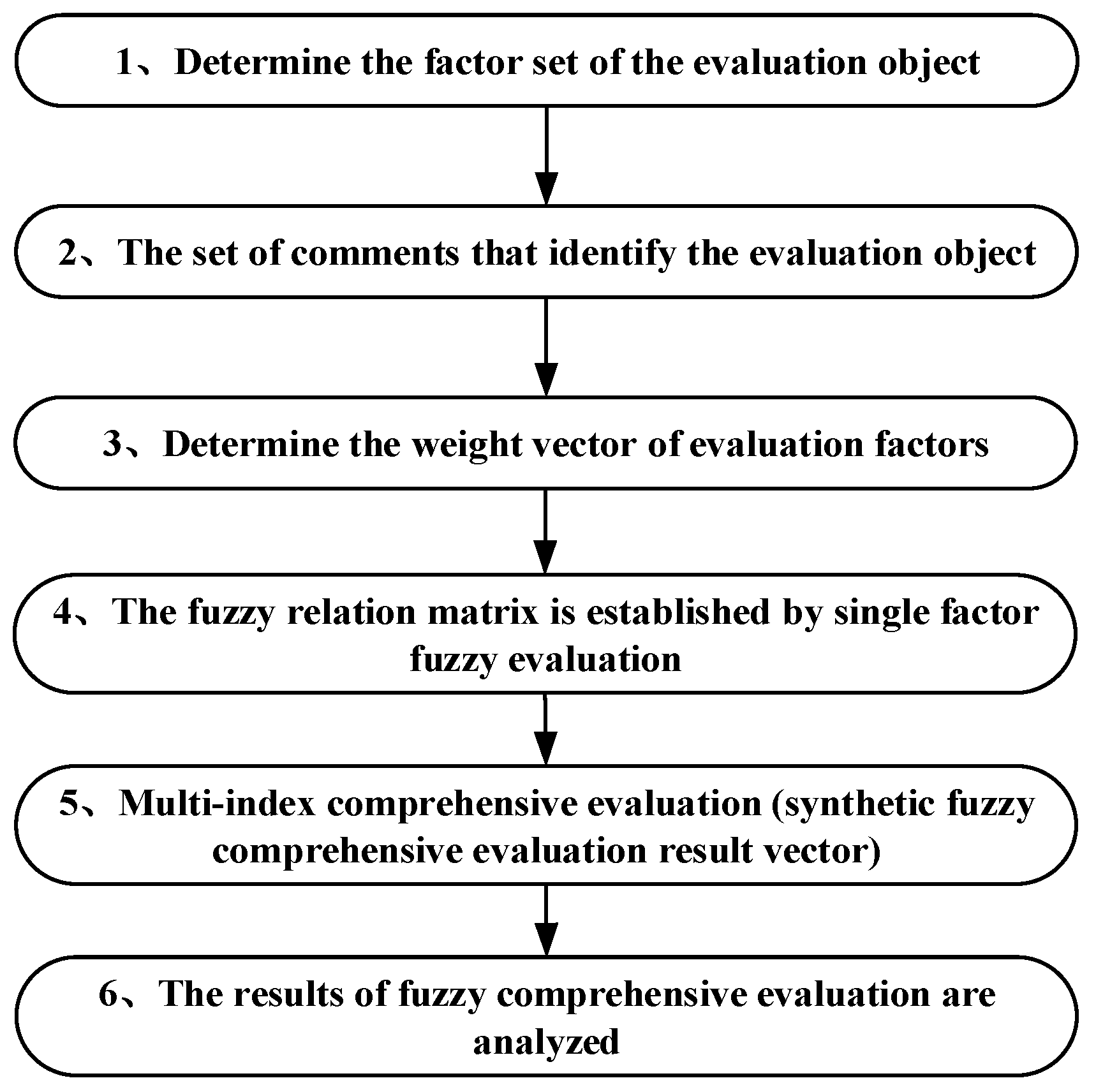
3. Fuzzy FMECA of PMSM

People have done a lot of research on the FMECA of EMA. Most of them told us that PMSM failure is a fault with high probability and severity in EMA [27,28]. Therefore, we built a fuzzy FMECA model and used PMSM as an example to analyze. The model and method carried out can also be used on EMA and other parts of it.
The base point of fuzzy FMECA is fuzzy processing of CA. Figure 3 shows the process. Firstly, the set of factors to be evaluated by FMECA was clearly defined. Then, the weight of each factor and its subordinate vector were determined one by one, and the fuzzy comprehensive evaluation matrix was obtained. Then the fuzzy evaluation matrix and the weight vector of the factors were calculated and normalized to get the fuzzy comprehensive evaluation result. The feature of this method is that the evaluation objects were executed one by one so that the evaluation objects had a unique evaluation value and the constraints of the collection where the evaluation objects are located were removed. The comprehensive evaluation is the process of selecting a winner from a set of objects, which requires evaluating the obtained objects. All data came from experimental statistics and expert experience.

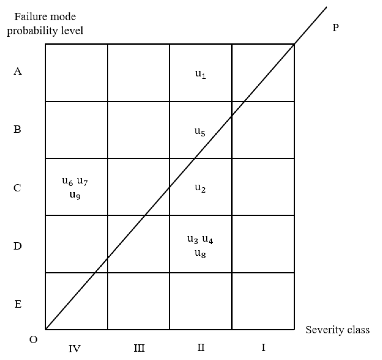
3.1. Traditional FMECA of PMSM

Before analyzing the PMSM of EMA using Fuzzy FMECA, we first used traditional FMECA analysis methods to verify the accuracy of subsequent methods. We simultaneously compared and analyzed the superiority of the improved method between the two.
The failure mode of PMSM that needed to be evaluated is shown in Table 1. The failure mode probability level and the severity class are also shown in Table 2. All of them will be used in the FMECA of PMSM.
We used these data to draw the hazard matrix diagram as shown in Figure 4. All of the failure factors, failure mode probability levels, and severity classes come from the experience of engineering experts and experimental results.
According to the hazard matrix diagram, we can roughly rank the fault risk level of PMSM as follows. The parentheses indicate that the specific risk-level ranking cannot be determined.
u 1 > u 5 > u 2 > ( u 3 , u 4 , u 6 , u 7 , u 8 , u 9 )
It can be seen that traditional FMECA can only give us a general rank of the failure mode of PMSM. As a result, we used fuzzy FMECA for further study.

3.2. Determine the Factor Set of PMSM

When assessing the risk of failure of EMA, its factor set (secondary index) was:
U = U 1 , U 2 , U 3
In the equation, U 1 was the frequency of failure modes; U 2 was the severity of impact; U 3 was the difficulty of detection.
Among them, each factor U i ( i = 1 , 2 , 3 ) was determined by the basic factors of PMSM fault hazard analysis and evaluation.
The factor set (first-order index) of the failure mode U i that needed to be evaluated for PMSM was:
U i = u 1 , u 2 , , u 9
In the equation, u i ( i = 1 , 2 9 ) was the failure mode of PMSM that needed to be evaluated, as shown in Table 1:

3.3. Determine the Comments Set of PMSM

The comment set on the frequency of failure modes U 1 was: V 1 = {often ( v 11 ), sometimes ( v 12 ), occasionally ( v 13 ), rarely ( v 14 )};
The comment set on the severity of the impact U 2 was: V 2 = {catastrophic ( v 21 ), severe ( v 22 ), critical ( v 23 ), minor ( v 24 )};
The comment set on the difficulty of detection U 3 was: V 3 = {difficult to detect ( v 31 ), able to detect ( v 32 ), relatively easy to detect ( v 33 ), easy to detect ( v 34 )}.

3.4. Determine the Fuzzy Evaluation Matrix of PMSM

To obtain the fuzzy evaluation matrix, 10 experienced experts from the expert investigation method were used to conduct a questionnaire. The number of times n j j = 1 , 2 , , 9 mentioned by each comment in each factor u i ( i = 1 , 2 , , 9 ) was counted, and then the probability P j = n j / 10 of the comments on this factor was obtained. For example, by analyzing the comments of 10 questionnaires on factor u 1 (interturn short circuit fault), we can get the comments v 1 i ( i = 1 , 2 , , 4 ) mentioned n 1 = 6 ,   n 2 = 3 ,   n 3 = 1 ,   n 4 = 0 respectively, and the according to P j = n j / 10 , calculate the comment set of factor evaluation vector is: r 1 = 0.6 ,   0.3 ,   0.1 ,   0 .
Secondly, the statistics and calculation of the collected 10 questionnaires were carried out according to the same method, and the evaluation vectors of the factors u 2 , u 3 , u 4 , u 5 , u 6 , u 7 , u 8 , u 9 of the evaluation set V 1 were obtained successively, as follows:
r 2 = 0 ,   0.4 ,   0.6 ,   0 , r 3 = 0 ,   0 ,   0.3 ,   0.7 , r 4 = 0 ,   0 ,   0.4 ,   0.6 , r 5 = 0.3 ,   0.5 ,   0.2 ,   0 ,
r 6 = 0 ,   0.5 ,   0.4   , 0.1 , r 7 = 0 ,   0.4 ,   0.5 ,   0.1 , r 8 = 0 ,   0.1 ,   0.3 ,   0.6 , r 9 = 0 ,   0.4 ,   0.5 ,   0.1
Thus, the fuzzy evaluation matrix R 1 of V 1 to U 2 can be obtained:
          R 1   = 0.6 0.3 0.1 0 0 0.4 0.6 0 0 0 0.3 0.7 0 0 0.4 0.6 0.3 0.5 0.2 0 0 0.5 0.4 0.1 0 0.4 0.5 0.1 0 0.1 0.3 0.6 0 0.4 0.5 0.1
R 2 and R 3 can be obtained by the same method:
  R 2 = 0.2 0.5 0.3 0 0 0.6 0.4 0 0 0.6 0.3 0.1 0 0.5 0.5 0 0.1 0.5 0.4 0 0 0.2 0.5 0.3 0 0.1 0.5 0.4 0 0.6 0.4 0 0 0.5 0.3 0.2                           R 3 = 0 0.7 0.3 0 0 0.4 0.6 0 0 0.5 0.3 0.2 0 0.4 0.3 0.3 0 0.6 0.4 0 0 0.1 0.4 0.5 0 0.2 0.5 0.3 0 0.1 0.3 0.6 0 0.4 0.4 0.2

3.5. Determine the Weight by the Analytic Hierarchy Method

Due to the different degree of influence of each fault factor on the safe operation of PMSM, the importance degree of each fault factor in the evaluation of PMSM, namely the weight, should be calculated during the comprehensive evaluation. In this paper, we used the analytic hierarchy method to obtain the weight set W = w 1 , w 2 , , w 9 ,   0 < w i < 1 .
(1) Randomly take an expert questionnaire and determine the three-scale matrix table of each fault factor of PMSM, as shown in Table 3.
(2) Equation (4) can be used to convert the three-scale scale into a nine-scale scale.
b i j = r i r j r m a x r m i n b m 1 + 1 , r i r j r j r i r m a x r m i n b m 1 + 1 1 , r i < r j
In the equation, b m is the base point comparison scale, which is 9 when converted into a nine-scale scale.
Table 3 shows that r m a x = 17 , r m i n = 2 , r 1 = 17 , r 2 = 13 , r 3 = 10 , r 4 = 10 , r 5 = 15 , r 6 = 6 , r 7 = 2 , r 8 = 2 , r 9 = 6 .
The nine-scale matrix table can be obtained through calculation, as shown in Table 4.
(3) According to Table 4, the square root method was used to obtain the weight vector and maximum eigenvalue of each fault factor. The specific idea of the square root method is to obtain the weight vector by applying geometric average and normalization methods to each row vector of the evaluation matrix A. The specific operation rules are as follows:
(1) Calculate the nth roots of operator of each line of the evaluation matrix:
ω ¯ i = j = 1 n a i j 1 n ( i = 1 , 2 , , n )
(2) Normalized processing:
w i = ω ¯ i / j = 1 n ω ¯ i ( i = 1 , 2 , , n )
Therefore, W = ( w 1 , w 2 , , w n ) T was the eigenvector obtained, that is, the relative weight obtained by scoring experts. Then, the weight of each factor can be obtained by arithmetic average of the results.
(3) Calculate the maximum eigenvalue of the judgment matrix
λ m a x = 1 n i = 1 n ( A w ) i w i
In the equation, ( A w ) i was the i th component of A W .
The weight vector and maximum eigenvalue of each fault factor of PMSM can be calculated:
W 1 = ( 0.3162,0.1584,0.0888,0.0888,0.2273,0.0406,0.0196,0.0196,0.0406 )
(4) The same method was used to calculate the remaining nine expert questionnaires, to exclude the questionnaires that did not meet the consistency requirements, and to determine the effective weight value of each expert.
W 2 = ( 0.3081,0.1570,0.1084,0.0743,0.2235,0.0352,0.0247,0.0179,0.0509 )
W 3 = ( 0.3081,0.1084,0.1570,0.0509,0.2235,0.0179,0.0352,0.0247,0.0743 )
W 4 = ( 0.2713 , 0.1306 , 0.1306 , 0.0727 , 0.2713 , 0.0338 , 0.0235 , 0.0169 , 0.0494 )
W 5 = ( 0.3081,0.0743,0.1570,0.1084,0.2235,0.0509,0.0179,0.0247,0.0352 )
W 6 = ( 0.3081,0.1570,0.0743,0.1084,0.2235,0.0509,0.0247,0.0352,0.0179 )
W 7 = ( 0.2812,0.2812,0.0857,0.0857,0.1585,0.0205,0.0205,0.0205,0.0461 )
W 8 = ( 0.3081,0.2235,0.0743,0.1084,0.1570,0.0509,0.0247,0.0352,0.0179 )
W 9 = ( 0.3081,0.0743,0.1084,0.1570,0.2235,0.0179,0.0509,0.0352,0.0247 )
W 10 = ( 0.2766,0.0714,0.1301,0.1301,0.2766,0.0184,0.0392,0.0392,0.0184 )
Finally, the average value of each weight was taken to obtain the weight distribution of the primary index of each fault factor of the PMSM. With the same method, the weight of each secondary index of PMSM can be calculated. The weights of primary indicators and secondary indicators of PMSMs are shown in Table 5 and Table 6.

3.6. Primary Fuzzy Comprehensive Evaluation of PMSM

There are many factors affecting PMSM. To comprehensively consider the influence of all fault factors, the weighted average method was adopted in this paper to carry out the primary comprehensive evaluation of PMSM. According to Equation (8), the primary evaluation model of PMSM can be written as Equation (9).
B = W · R = w 1 , w 2 , , w m r 11 r 12 r 1 n r 21 r 22 r 2 n r m 1 r m 2 r m n = ( b 1 , b 2 , , b n )
b j = i = 1 i = 9 ( w i , r i j )
W = ( 0.29939,0.14361,0.11146,0.09847,0.22082,0.0337,0.02809,0.02691,0.03754 )
The results of first-order fuzzy comprehensive evaluation of factors U 1 , U 2 , and U 3 were obtained by calculation:
B 1 = W R 1 = ( 0.24588,0.303464,0.287463,0.163183 )
B 2 = W R 2 = ( 0.08196,0.506847,0.371183,0.062292 )
B 3 = W R 3 = ( 0,0.521322,0.377904,0.100764 )
Then the normalization of B 1 , B 2 , and B 3 can be obtained:
B 1 1 = ( 0.24588,0.303464,0.287463,0.163183 )
B 2 2 = ( 0.08196,0.506847,0.371183,0.062292 )
B 3 3 = ( 0,0.521322,0.377904,0.100764 )
Based on B 1 1 , B 2 2 , and B 3 3 , the primary fuzzy comprehensive evaluation conclusion of PMSM can be obtained:
(1) Frequency of failure. A total of 24.588% of experts evaluated that PMSM failures often happen, 30.3464% of experts evaluated that PMSM failures sometimes happen, 28.7463% of experts evaluated that PMSM failures happen occasionally, and 16.3183% of experts evaluated that PMSM failures rarely happen. Therefore, the largest proportion is the evaluation of PMSM fault sometimes happen experts. According to the principle of maximum membership, the failure frequency of PMSM can be considered as sometimes occurring. According to the evaluation criterion of risk priority number method, it can be found that the probability of this situation happens sometimes.
(2) The severity of the impact. A total of 8.196% of the experts evaluated that the PMSM fault would cause catastrophic impact, 50.6847% of the experts evaluated that the PMSM fault would cause serious impact, 37.1183% of the experts evaluated that the PMSM fault would cause critical impact, and 6.2292% of the experts evaluated that the PMSM fault would cause minor impact. So, the largest proportion is the evaluation of PMSM failure will cause serious impact experts. According to the principle of maximum subordination, it is considered that the PMSM fault will cause serious impact, and the evaluation results were basically consistent with the reality.
(3) Degree of detection difficulty. All the experts believed that the PMSM fault can be detected, among which 52.1322% of experts evaluated that the PMSM fault can be detected, 37.7904% of experts evaluated that the PMSM fault was relatively easy to detect, and 10.0764% of experts evaluated that the PMSM fault was easy to detect. It can be seen that the PMSM fault can be detected during inspection.

3.7. Secondary Fuzzy Comprehensive Evaluation of PMSM

Based on the primary evaluation results, the secondary evaluation matrix of permanent magnet synchronous motor was obtained:
R = ( B 1 1 , B 2 2 , B 3 3 ) T = 0.24588 0.303464 0.287463 0.163183 0.08196 0.506847 0.371183 0.062292 0 0.521322 0.377904 0.100764
According to Table 6, the weights of U 1 , U 2 , and U 3 were W = ( 0.1488,0.7767,0.0745 ) , and the secondary evaluation of permanent magnet synchronous motor can be calculated as follows:
B 2 = W R = ( 0.100245276,0.4776619971,0.3592261785,0.0801707448 )

3.8. Sharpening of Evaluation Results of PMSM

The first-level evaluation conclusion was determined by the principle of maximum membership degree. This method focuses on the factors with a large membership degree and ignores the factors with a small membership degree. Due to the interference of the factors with a small membership degree on the evaluation results, to comprehensively consider all factors, it was necessary to use the gravity center method to deal with the second-level evaluation results. μ ( μ i ) 2 was selected as the weighting coefficient so that the factors with high membership can play a more important role in the conclusion. The calculation formula of gravity center method is as follows:
μ = i = 1 n μ ( μ i ) × μ i i = 1 n μ ( μ i )
In the equation, μ ( μ i ) was the weighting coefficient.
To reflect the influence of elements with the greater membership, the weighting coefficient can be changed to μ ( μ i ) 2 , and the calculation formula of the barycenter method was as follows:
μ = i = 1 n μ ( μ i ) 2 × μ i i = 1 n μ ( μ i ) 2
To be clear, the previous inconsistent comment sets V i ( i = 1 , 2 , 3 ) needed to be redefined and given a unified evaluation value to unify the three groups of comment sets, as shown in Table 7:
The improved clarity processing formula is:
B 0 = i = 1 4 b ( v i ) 2 × v i i = 1 4 b ( v i ) 2
In the equation, B 0 was the safety level of clear processing and b ( v i ) was the assignment corresponding to the unified comment set v i .
Substitute the second-level evaluation results into the Equation (12):
B 0 = 2.647
According to the evaluation criteria of relevant literature, the safety evaluation levels and suggested measures of permanent magnet synchronous motors were obtained, as shown in Table 8. As the result of secondary evaluation of permanent magnet synchronous motor was B 0   = 2.647, the evaluation grade of permanent magnet synchronous motor was generally safe.

3.9. Comprehensive CA Model for Evaluation of PMSM

In the first-level fuzzy comprehensive evaluation, three evaluation matrices of V to U were obtained. In these matrices, the evaluation matrix of each factor was composed of the row vector of fuzzy evaluation of the factor to the failure mode. For example, the first row of the evaluation matrix R 1 was the evaluation vector of the failure mode u 1 (short-circuit fault between turns of permanent magnet synchronous motor stator windings) from the fault occurrence frequency evaluation set V 1 of factor U 1 . The fuzzy evaluation matrix of each failure mode was obtained by extracting the corresponding rows of each evaluation matrix one by one.
For example, failure mode u 1 (interturn short circuit fault of stator winding), the corresponding rows of the extraction evaluation matrix can be obtained: fault frequency evaluation set R 1 1 , influence severity evaluation set R 2 1 , detection difficulty evaluation set R 3 1 .
R 1 1 = ( 0.6,0.3,0.1,0 ) ,   R 2 1 = ( 0.2,0.5,0.3,0 ) ,   R 3 1 = ( 0,0.7,0.3,0 )
The fuzzy evaluation matrix of failure mode u 1 was obtained by combining the three evaluation sets:
R 1 = 0.6 0.3 0.1 0 0.2 0.5 0.3 0 0 0.7 0.3 0
Based on the weight distribution W = ( 0.1488,0.7767,0.0745 ) of the above factors, the first-level fuzzy comprehensive evaluation of failure mode u 1 (interturn short circuit fault of stator winding) was calculated. The results were as follows:
B 1 = W R 1 = ( 0.2446,0.4851,0.2702,0 )
By using the weighted average model to synthesize the influence of each index on the system, the comprehensive hazard level of the failure mode u 1 (interturn short circuit fault of stator winding) was calculated:
C 1 = i = 1 4 b i v 1 = 2.9642
The same method was used to calculate the comprehensive hazard level of other failure modes of permanent magnet synchronous motor, and the fuzzy evaluation matrix of each failure mode can be written as follows:
R 2 = 0 0.4 0.6 0 0 0.6 0.4 0 0 0.4 0.6 0 ,   R 3 = 0 0 0.3 0.7 0 0.6 0.3 0.1 0 0.5 0.3 0.2 ,   R 4 = 0 0 0.4 0.6 0 0.5 0.5 0 0 0.4 0.3 0.3 , R 5 = 0.3 0.5 0.2 0 0.1 0.5 0.4 0 0 0.6 0.4 0 ,   R 6 = 0 0.5 0.4 0.1 0 0.2 0.5 0.3 0 0.1 0.4 0.5 ,   R 7 = 0 0.4 0.5 0.1 0 0.1 0.5 0.4 0 0.2 0.5 0.3 , R 8 = 0 0.1 0.3 0.6 0 0.6 0.4 0 0 0.1 0.3 0.6 ,   R 9 = 0 0.4 0.5 0.1 0 0.5 0.3 0.2 0 0.4 0.4 0.2 .
The first-level fuzzy comprehensive evaluation results of each failure mode were as follows:
B 2 = 0,0.55534,0.44466,0 , B 3 = 0,0.50327,0.3,0.19673 B 4 = ( 0,0.41815,0.47022,0.11163 ) ,   B 5 = ( 0.12231,0.50745,0.37024,0 ) B 6 = ( 0,0.23719,0.47767,0.28514 ) ,   B 7 = ( 0,0.15209,0.5,0.34791 ) , B 8 = ( 0,0.48835,0.37767,0.13398 ) , B 9 = ( 0,0.47767,0.33721,0.18512 ) .
The comprehensive hazard level of each failure mode was:
C 2 = 2.6093 ,   C 3 = 2.5617 ,   C 4 = 2.3976 ,   C 5 = 2.7018 , C 6 = 1.9315 ,   C 7 = 1.7516 ,   C 8 = 2.5526 ,   C 9 = 2.5155 .
The vector composed by the comprehensive hazard level of each failure mode can be obtained as follows:
C = C 1 , C 2 , , C 9 = ( 2.9642,2.6093,2.5617,2.3976,2.7018,109315,1.7516,2.5526,2.5155 )
The hazard degree of each failure mode of permanent magnet synchronous motor can be sorted according to the calculated comprehensive hazard level. The result of risk ranking reflects the risk of each failure mode of permanent magnet synchronous motor. Based on this, corrective measures can be taken for the high-risk failure modes.
The risk ranking sequence of permanent magnet synchronous motor was:
u 1 > u 5 > u 2 > u 3 > u 8 > u 9 > u 4 > u 6 > u 7
It can be seen that u 1 (interturn short circuit fault) is the failure mode with the highest risk of failure in PMSM.
In this chapter, we first conducted a fault mode analysis of PMSM in EMA using the traditional FMECA method and obtained a relatively inaccurate conclusion. Subsequently, an improved fuzzy FMECA method was adopted to analyze PMSM. Comparing the results of the two analyses, it is not difficult to find that the analysis results of the fuzzy FMECA method were basically the same as those of the traditional FMECA method and were more accurate, accurately ranking the importance of each fault. Furthermore, due to the presence of expert ratings, we can roughly estimate the importance of each fault based on its risk rating, providing a reliable basis for monitoring and preventing faults.

4. Conclusions

In view of the diverse working conditions of EMA, a variety of faults will inevitably occur. To facilitate PHM for EMA, a comprehensive analysis of its fault modes was required. The major efforts and significant conclusions are summarized as follows:
(1)
This paper analyzed the structure and working principle of EMA, comprehensively analyzed the four components and working principles of EMA, laid the foundation for the subsequent failure mode analysis, and identified PMSM as the research object.
(2)
The traditional FMECA method was used to analyze nine common faults of PMSM, the most important components of EMA. The results showed a general rank of the risk of the failure modes of PMSM, but we cannot get the specific ranking of failure modes.
(3)
In view of the limitation of the traditional FMECA method, which is easily affected by subjective factors, fuzzy comprehensive evaluation was applied to quantify the qualitative evaluation index. Then, the fuzzy FMECA model based on fuzzy comprehensive evaluation was constructed. Nine kinds of faults in PMSM were analyzed and ranked by the FMECA method based on fuzzy comprehensive evaluation.
(4)
Finally, the results of fuzzy FMECA were compared with traditional FMECA. It came out that fuzzy FMECA can bring out a more precise and quantitative result. Both the results showed that the interturn short-circuit fault was the riskiest fault in PMSM.
(5)
In the future, we will conduct further research and experiments on the fault diagnosis and prediction of PMSM in EMA based on the research results of this article, combined with deep learning.

Author Contributions

Conceptualization, C.Z. and X.L.; Methodology, C.Z. and B.C.; Validation, B.C.; Formal analysis, X.L.; Investigation, B.C.; Resources, C.Z.; Data curation, C.Z.; Writing—original draft, B.C.; Writing—review and editing, C.Z. and X.L.; Supervision, C.Z. All authors have read and agreed to the published version of the manuscript.

Funding

This work is partially supported by the National Key Scientific Research Projects of China (JSZL2022607B002, JSZL202160113001, and JCKY2021608B018) and the Fundamental Research Funds for the Central Universities (HYGJXM202310, HYGJXM202311, and HYGJXM202312). The authors also gratefully acknowledge the helpful comments and suggestions of the reviewers, which have improved the presentation.

Institutional Review Board Statement

Not applicable.

Informed Consent Statement

Not applicable.

Data Availability Statement

Data are contained within the article.

Conflicts of Interest

Author Xiangzhi Li was employed by the company Chengdu Kaitian Electronics Co., Ltd. The remaining authors declare that the research was conducted in the absence of any commercial or financial relationships that could be construed as a potential conflict of interest.

References

  1. Canciello, G.; Cacciapuoti, L.; Perrotta, A.; Guida, B.; Cavallo, A. Multi-Objective Supervisory Control in More-Electric Aircraft Using Model Predictive Control: An ORCHESTRA Application. Energies 2024, 17, 3799. [Google Scholar] [CrossRef]
  2. Wang, L.; Dai, Z.; Yang, S.; Mao, L.; Yan, Y. Overview of Research on Intelligent Design of Electrified Aircraft Power System. Chin. J. Aeronaut. 2019, 40, 522405. (In Chinese) [Google Scholar]
  3. Li, M.; Wang, Y.; Peng, P.; Chen, Z. Toward efficient smart management: A review of modeling and optimization approaches in electric vehicle-transportation network-grid integration. Green Energy Intell. Transp. 2024, 3, 100181. [Google Scholar] [CrossRef]
  4. Zhang, X.; Huang, J. Overview of the Development of High Power, High Performance and Redundancy Aerospace Electric Servo Technology. Navig. Position. Timing 2017, 4, 1–7. (In Chinese) [Google Scholar]
  5. Qiao, G.; Liu, G.; Shi, Z.; Wang, Y.; Ma, S.; Lim, T.C. A review of electromechanical actuators for more/all electric aircraft systems. Proc. Inst. Mech. Eng. Part C J. Mech. Eng. Sci. 2018, 232, 4128–4151. [Google Scholar] [CrossRef]
  6. Bertolino, A.C.; De Martin, A.; Jacazio, G.; Sorli, M. Design and Preliminary Performance Assessment of a PHM System for Electromechanical Flight Control Actuators. Aerospace 2023, 10, 335. [Google Scholar] [CrossRef]
  7. Wang, J.; Zhang, H.; Miao, Q. An attention graph stacked autoencoder for anomaly detection of electro-mechanical actuator using spatio-temporal multivariate signals. Chin. J. Aeronaut. 2024, 37, 506–520. [Google Scholar] [CrossRef]
  8. Sulaiman, S.F.; Ngateni, N.A.; Osman, K.; Samsudin, S.I.; Sulaiman, N.A.; Sunar, N. Modeling and Development of Predictive Controller for Positioning Control of Electro-Hydraulic Actuator (EHA) System. Przegląd Elektrotechniczny 2024, 2024, 177–181. [Google Scholar] [CrossRef]
  9. Du, S.; Zhou, J.; Hong, J.; Zhao, H.; Ma, S. Application and progress of high-efficiency electro-hydrostatic actuator technology with energy recovery: A comprehensive review. Energy Convers. Manag. 2024, 321, 119041. [Google Scholar] [CrossRef]
  10. Yin, Z.; Hu, N.; Chen, J.; Yang, Y.; Shen, G. A review of fault diagnosis, prognosis and health management for aircraft electromechanical actuators. IET Electr. Power Appl. 2022, 16, 1249–1272. [Google Scholar] [CrossRef]
  11. de la Hoz, C.C.; Fioriti, M.; Boggero, L. Performance and Reliability Evaluation of Innovative High-Lift Devices for Aircraft Using Electromechanical Actuators. Aerospace 2024, 11, 468. [Google Scholar] [CrossRef]
  12. Yang, Z.; Sun, X.; Yang, J.; Mao, Q. Review of fault diagnosis technology for flight electromechanical actuation system. Electr. Drive 2022, 52, 3–11. (In Chinese) [Google Scholar]
  13. Spreafico, C.; Russo, D.; Rizzi, C. A state-of-the-art review of FMEA/FMECA including patents. Comput. Sci. Rev. 2017, 25, 19–28. [Google Scholar] [CrossRef]
  14. Luo, X.; He, H.; Zhang, X.; Ma, Y.; Bai, X. Failure Mode Analysis of Intelligent Ship Positioning System Considering Correlations Based on Fixed-Weight FMECA. Processes 2022, 10, 2677. [Google Scholar] [CrossRef]
  15. Liu, C.; Zhou, C.; Tan, L.; Cui, J.; Xiao, W.; Liu, J.; Wang, H.; Wang, T. Reliability analysis of subsea manifold system using FMECA and FFTA. Sci. Rep. 2024, 14, 22873. [Google Scholar] [CrossRef]
  16. Elidolu, G.; Teixeira, Â.P.; Arslanoğlu, Y. A risk assessment of inhibited cargo operations in maritime transportation: A case of handling styrene monomer. Ocean Eng. 2024, 312, 119049. [Google Scholar] [CrossRef]
  17. Tian, J.; Shi, E.; Zhong, J.; Chen, Y.; Deng, X.; Li, G. Reliability Analysis and Structural Optimization of Circuit Board Based on Vibration Mode Analysis and Random Vibration. Processes 2024, 12, 1726. [Google Scholar] [CrossRef]
  18. Yousaf, A.; Amro, A.; Kwa, P.T.H.; Li, M.; Zhou, J. Cyber risk assessment of cyber-enabled autonomous cargo vessel. International Journal of Critical Infrastructure Protection. Int. J. Crit. Infrastruct. Prot. 2024, 46, 100695. [Google Scholar] [CrossRef]
  19. Huang, C.; Wu, J.; Shan, Z.; Wang, Q.; Yu, Z. Reliability Prediction for New Prefabricated Track Structures Based on the Fuzzy Failure Modes, Effects, and Criticality Analysis Method. Appl. Sci. 2024, 14, 5338. [Google Scholar] [CrossRef]
  20. Zhang, Y.; Fang, L.; Zhao, J.; Qi, Z.; Deng, H. An improved FMECA method for equipment reliability based on information fusion. Phys. Scr. 2024, 99, 055207. [Google Scholar] [CrossRef]
  21. Sezer, S.I.; Camlıyurt, G.; Aydin, M.; Akyuz, E.; Boustras, G.; Park, S. A holistic risk assessment under the D–S evidential theory and FMECA approach of ship recycling process hazards in the maritime environment. Hum. Ecol. Risk Assess. Int. J. 2024, 30, 201–216. [Google Scholar] [CrossRef]
  22. Castro, P.F.; de Lira, G.R.S.; Vilar, P.B.; Vilar, P.B.; Costa, E.G.d.; Carvalho, F.B.S. Fuzzy Inference System Development for Turbogenerator Failure Diagnosis on Floating Production Offloading and Storage Platform. Energies 2024, 17, 392. [Google Scholar] [CrossRef]
  23. Zhou, Q.; Li, H.; Zeng, X.; Li, L.; Cui, S.; Du, Z. A quantitative safety assessment for offshore equipment evaluation using fuzzy FMECA: A case study of the hydraulic submersible pump system. Ocean Eng. 2024, 293, 116611. [Google Scholar] [CrossRef]
  24. Zúñiga, A.A.; Fernandes, J.F.P.; Branco, P.J.C. Fuzzy-Based Failure Modes, Effects, and Criticality Analysis Applied to Cyber-Power Grids. Energies 2023, 16, 3346. [Google Scholar] [CrossRef]
  25. del Olmo, A.; de Lacalle, L.N.L.; Martínez de Pissón, G.; Pérez-Salinas, C.; Ealo, J.A.; Sastoque, L.; Fernandes, M.H. Tool wear monitoring of high-speed broaching process with carbide tools to reduce production errors. Mech. Syst. Signal Process. 2022, 172, 109003. [Google Scholar] [CrossRef]
  26. Aldekoa, I.; del Olmo, A.; Sastoque-Pinilla, L.; Sendino-Mouliet, S.; Lopez-Novoa, U.; de Lacalle, L.N.L. Early detection of tool wear in electromechanical broaching machines by monitoring main stroke servomotors. Mech. Syst. Signal Process. 2023, 204, 110773. [Google Scholar] [CrossRef]
  27. Huangfu, H.; Zhou, Y.; Zhang, J.; Ma, S.; Fang, Q.; Wang, Y. Research on Inter-Turn Short Circuit Fault Diagnosis of Electromechanical Actuator Based on Transfer Learning and VGG16. Electronics 2022, 11, 1232. [Google Scholar] [CrossRef]
  28. Zhang, C.; Li, X.; He, S.; Zhou, D.; Zhou, Y. Failure Modes, Effect and Criticality Analysis of Electro-Mechanical Actuator; ICIC: Tianjin, China, 2024. [Google Scholar]
Figure 1. Basic information and general structure of EMA on an airplane.
Actuators 13 00510 g001
Figure 2. Structure and principle of EMA.
Actuators 13 00510 g002
Figure 3. Flow chart of fuzzy FMECA.
Actuators 13 00510 g003
Figure 4. Hazard matrix diagram of PMSM.
Actuators 13 00510 g004
Table 1. Classification of the probability of failure mode occurrence.
Serial NumberFailure Factors of PMSM
u 1 Interturn short circuit fault of stator windings
u 2 Phase to phase short-circuit fault of stator windings
u 3 Ground fault
u 4 Open-circuit fault
u 5 Demagnetizing fault of permanent magnet
u 6 Fatigue fault of bearings
u 7 Corrosion fault of bearings
u 8 Fracture fault of bearings
u 9 Eccentricity fault of rotor
Table 2. The failure mode probability level and the severity class of each failure factor.
Serial NumberFailure Mode Probability LevelSeverity Class
u 1 IIA
u 2 IIC
u 3 IID
u 4 IID
u 5 IIB
u 6 IVC
u 7 IVC
u 8 IID
u 9 IVC
Table 3. Classification of the probability of failure mode occurrence.
A j A 1 A 2 A 3 A 4 A 5 A 6 A 7 A 8 A 9 r i
A i
A 1 12222222217
A 2 01220222213
A 3 00110222210
A 4 00110222210
A 5 02221222215
A 6 0000012216
A 7 0000001102
A 8 0000001102
A 9 0000012216
Table 4. Nine-scale matrix table of the failure factors of PMSM.
A j A 1 A 2 A 3 A 4 A 5 A 6 A 7 A 8 A 9
A i
A 1 147/1571/1571/1531/15103/1599103/15
A 2 15/47113/513/515/3171/15103/15103/1571/15
A 3 15/715/13113/1147/1579/1579/1547/15
A 4 15/715/13113/1147/1579/1579/1547/15
A 5 15/3131/1511/311/3129/5119/15119/1529/5
A 6 15/10315/7115/4715/475/29147/1547/151
A 7 1/915/10315/7915/7915/11915/471115/47
A 8 1/915/10315/7915/7915/11915/471115/47
A 9 15/10315/7115/4715/475/29147/1547/151
Table 5. The weight of each level index in PMSM.
Factor   ( u i ) u 1 u 2 u 3 u 4 u 5 u 6 u 7 u 8 u 9
weight ( w i )0.299390.143610.111460.098470.220820.03370.028090.026910.03754
Table 6. The weight of each secondary index in PMSM.
Factor   ( U i ) Frequency of FaultSeverity of ImpactThe Difficulty of
Detection
Weight ( W i )0.14880.77670.0745
Table 7. Collection of comments after unification.
Original   ( i = 1 , 2 , 3 ) Post-UnificationCommentValue
v i 1 v 1 Relatively bad4
v i 2 v 2 Bad3
v i 3 v 3 Relatively good2
v i 4 v 4 Very good1
Table 8. Evaluation level and recommended measures.
Evaluation LevelRecommended MeasuresSafety Level
B 0 < 1.5
(Very good)
The system works well, each performance is intact, without special treatmentVery safe
1.5 B 0 < 2.5
(Relatively good)
The system has a small possibility of failure, only need to strengthen the regular maintenance and inspection of some weak partsRelatively safe
2.5 B 0 < 3.5
(In general)
The system has some fault possibilities, so it is necessary to maintain the weak parts regularly and make some improvement measures at the same time to prevent the failureGenerally safe
3.5 B 0 < 4.5
(Relatively bad)
The system has a relatively large possibility of failure, so it is necessary to maintain the weak parts regularly and make some improvement measures at the same time, to reduce the probability and influence of failureRelatively unsafe
B 0 4.5
(Very bad)
The system has a great possibility of failure, and it needs to improve the weak parts. Finally, the improved system is re-evaluated to improve the reliability of the system to meet the requirementsVery unsafe
Disclaimer/Publisher’s Note: The statements, opinions and data contained in all publications are solely those of the individual author(s) and contributor(s) and not of MDPI and/or the editor(s). MDPI and/or the editor(s) disclaim responsibility for any injury to people or property resulting from any ideas, methods, instructions or products referred to in the content.

