1. Introduction
Permanent magnet synchronous motors (PMSMs) have gained widespread adoption due to their high power density, superior performance, and substantial overload capacity. For high-precision Field-Oriented Control (FOC), obtaining accurate rotor position information is of paramount importance. Although Hall sensors and rotary encoders are commonly used for this purpose, they introduce challenges such as increased size, higher costs, and elevated fault rates in motor control systems. To address these issues, sensorless control technology for permanent magnet synchronous motors has emerged [
1,
2,
3]. When the motor operates at medium-to-high speeds, using the back-electromotive force estimation method can effectively obtain accurate rotor position information. Techniques such as sliding mode observers and extended Kalman filters are commonly employed to extract the rotor position from the fundamental waveforms [
4,
5,
6,
7]. However, due to the small back-electromotive force of the motor at low speeds and its vulnerability to interference, the estimation performance becomes poor. To address the issue of poor rotor position estimation performance using the back-EMF method at low speeds, many researchers have proposed rotor flux observers [
8,
9].
Currently, common parameter identification methods include least squares, model reference adaptive systems (MRASs), extended Kalman filters, and artificial intelligence algorithms. Recursive least squares are fast and simple but may become inaccurate due to data saturation [
10]. Some researchers have proposed an online identification method for PMSM parameters based on cascade MRAS. Using Popov’s hyperstability theory, an identification model for motor parameters is established in the d-q axis coordinate system. By choosing an appropriate adaptation rate, the rotor flux can be accurately estimated [
11]. MRASs are accurate and straightforward for single or dual parameter identification, but their observation accuracy decreases when identifying multiple parameters due to rank deficiency issues. Some researchers have proposed an improved, step-by-step, MRAS-based online identification method. Initially, the stator resistance and rotor flux are identified. Once these results stabilize, the stator inductance is identified, allowing for multi-parameter identification within a single model [
12]. The accuracy of EKF parameter estimation heavily depends on the noise matrices and accurate modeling, which are not straightforward to determine. Some studies employ the ACA algorithm to derive noise matrices, while others use second-order EKF state observer equations to construct multi-parameter identification models for PMSMs [
13,
14]. However, these algorithms are complex and difficult to adjust, and artificial intelligence algorithms present even higher complexity and computational demands, posing significant challenges to hardware system processing capabilities.
The rotor flux linkage observer method utilizes current and flux linkage equations in the two-phase stationary coordinate system to observe the motor’s rotor flux linkage. The rotor flux linkage contains rotor position information, which can be decoupled using arctangent or phase-locked loop (PLL) methods to obtain the rotor position. Nonlinear flux linkage models can accurately estimate rotor position under precise motor parameters. However, during motor operation, parameter variations caused by current and temperature changes affect performance. Some researchers have pointed out that temperature changes can result in errors of up to 40% in stator resistance and 20% in rotor flux linkage [
15]. The error compensation term in the nonlinear flux linkage model is corrected using the actual value of the motor’s rotor flux linkage. When the estimated rotor flux linkage equals the actual value, the observer reaches a stable state. However, when the rotor flux changes, it will greatly affect the output torque of the motor, which will make the system unstable. The dynamic equation of the flux linkage observer’s error indicates that the convergence of observation errors mainly depends on the observer’s gain and the motor’s rotor flux linkage and is less affected by changes in stator resistance. It has been proven through simulation experiments and experiments that the nonlinear flux observer has good robustness when the stator resistance suddenly changes. Therefore, this paper only discusses the impact of changes in rotor flux linkage on the observer’s performance. To address the issue of performance degradation in sensorless control algorithms due to motor parameter variations, researchers have proposed online parameter identification methods.
Since this study involves only single-parameter identification of rotor flux linkage, a MRAS and a nonlinear flux linkage model are combined to observe rotor position and speed, implemented through a PI controller, and the stability of the system is proven using Popov’s hyperstability theory and Lyapunov’s theory [
16,
17]. The rotor flux linkage value identified by the MRAS is fed into the nonlinear flux linkage model to continuously correct the estimated rotor flux linkage, requiring minimal computation and ensuring accurate identification. The simulation results demonstrate that the MRAS can accurately identify the rotor flux linkage value during both normal operation and sudden changes. When combined with the nonlinear flux linkage model, rotor position can be accurately estimated. The motor experimental platform built for verification demonstrates that the proposed control strategy improves motor response speed and rotor position estimation accuracy under conditions of low speed, heavy load, and torque mutation.
2. Rotor Flux Linkage Observation Based on MRAS
2.1. Basic Principle of MRAS
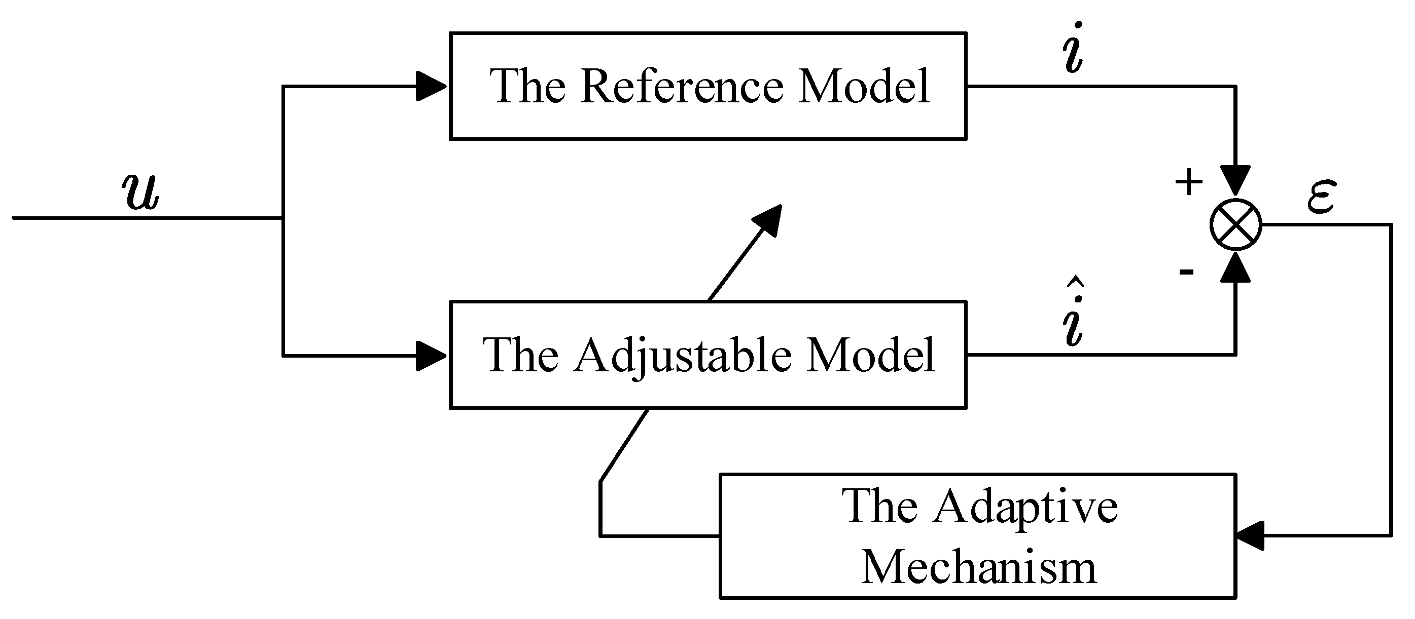
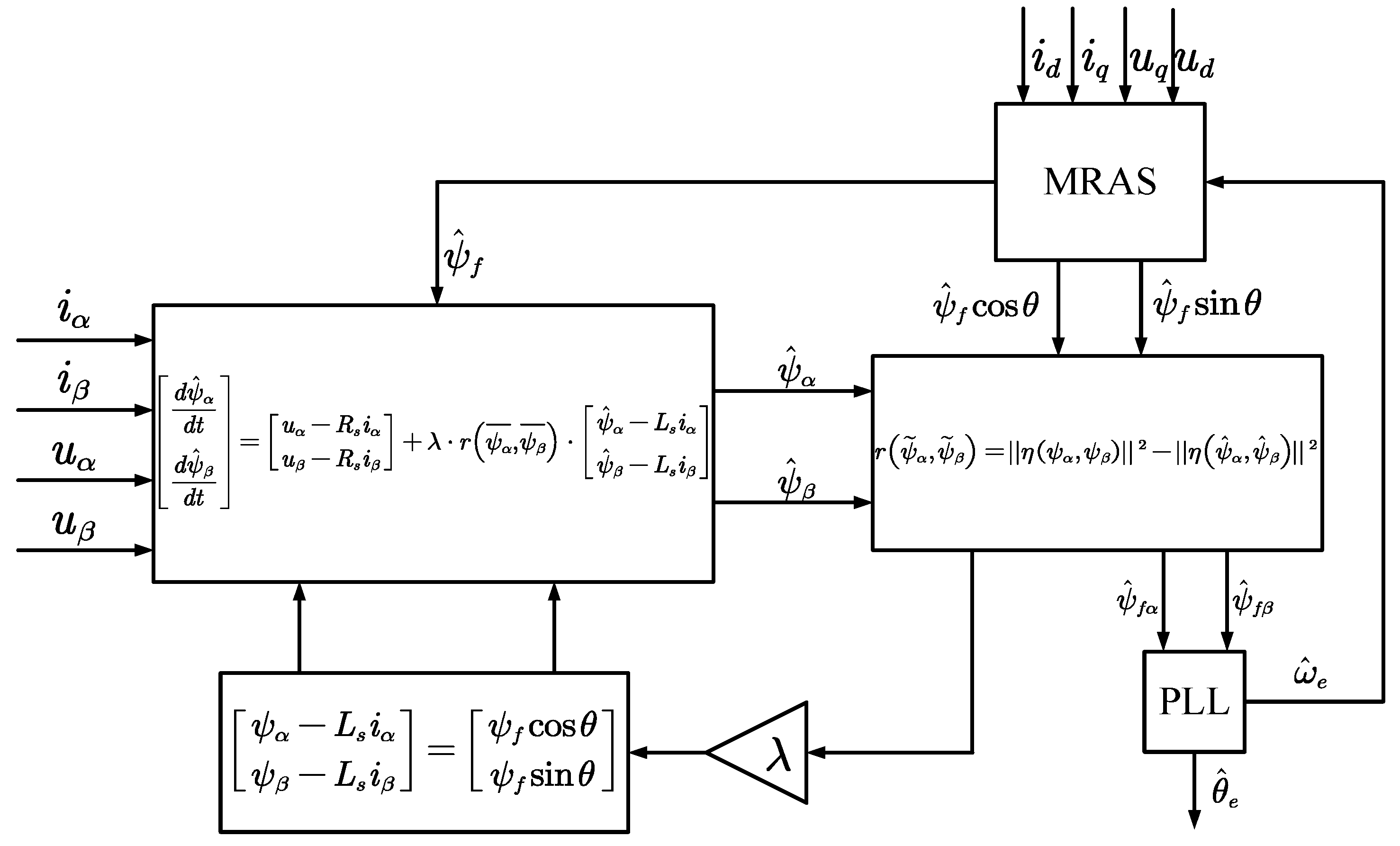
The MRAS algorithm comprises three key components: the reference model, the adjustable model, and the adaptive mechanism. The reference model represents the motor’s actual mathematical behavior, while the adjustable model incorporates estimated parameters. By selecting an appropriate adaptation rate, the output of the adjustable model is tuned to ensure the output error gradually approaches zero, at which point the identified parameters in the adjustable model converge to the motor’s true values. The structure is depicted in
Figure 1.
2.2. Rotor Flux Linkage Observation
PMSMs are complex systems characterized by multiple variables, strong coupling, nonlinearity, and time variance. When mathematically modeling them, the following assumptions are made: (1) the induced EMF generated by the motor’s three-phase windings is sinusoidal; (2) higher harmonics are neglected; and (3) core saturation and core loss are ignored.
Based on these assumptions, the stator voltage equations for PMSMs can be derived as in Equation (1):
For surface-mounted permanent magnet synchronous motors,
, and the above formula can be rewritten as follows:
By performing Clark and Park transformations on the collected three-phase currents, the actual current values are obtained. These values are used as the outputs of the reference model, while the currents obtained by integrating the equations serve as the outputs of the adjustable model.
Equation (2) is expressed in the form of Equation (3):
Representing the parameters to be estimated in Equation (3) as estimated values results in the adjustable model:
By taking the difference between Equations (3) and (4), we derive the error function of the reference model and the adjustable model:
By substituting Equations (3) and (4) into each other, we derive the following results:
In the equation: , .
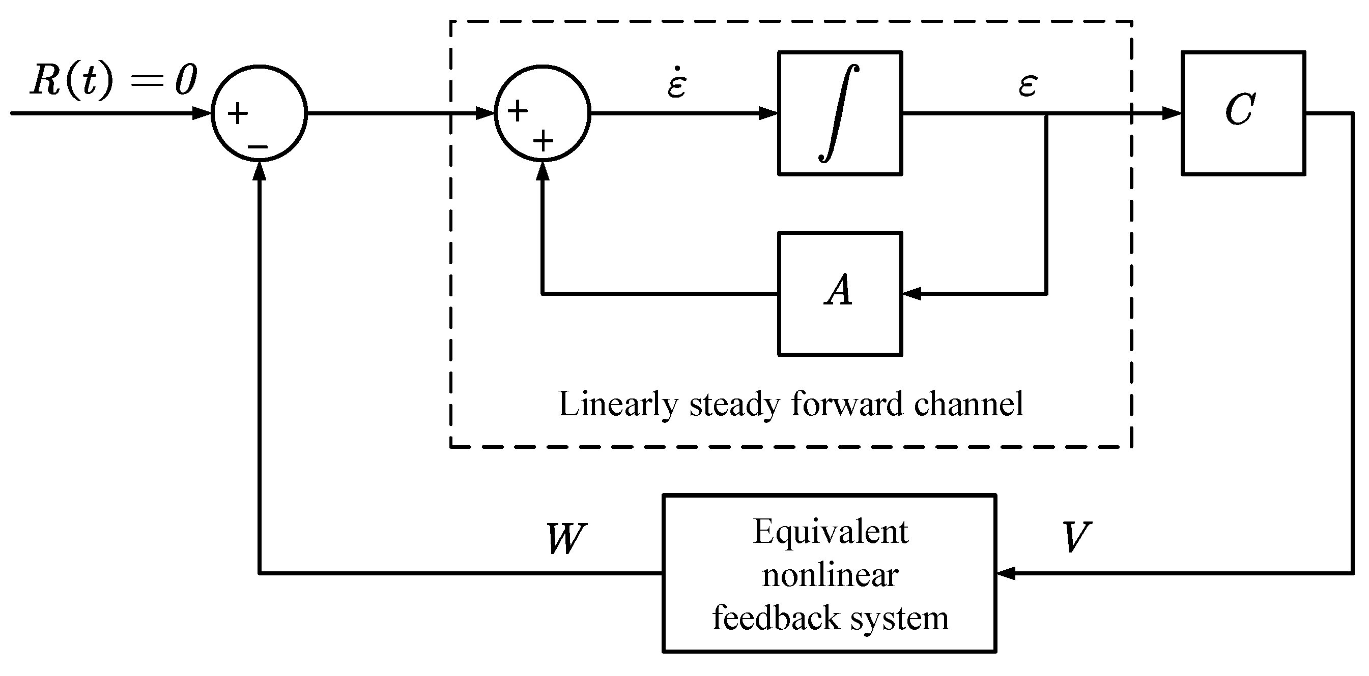
Based on the above equation, an equivalent nonlinear system is constructed as shown in
Figure 2.
According to Popov’s super stability theory, to maintain stability in this nonlinear feedback system, the following inequality must be satisfied:
In the equation, is a finite positive real number.
By substituting Equation (6) into the inequality, we obtain:
Analyzing Equation (8) reveals the following when the motor parameters are substituted:
By setting the adaptive rate in PI form, we obtain the following:
Substituting Equation (10) into Equation (9) yields:
To validate the above equation, an intermediate expression is introduced:
Differentiating both sides yields:
When substituting the above two equations into Equation (9), the condition is always satisfied.
Based on the above derivation, we can obtain the expression for the rotor flux adaptive rate.
2.3. Nonlinear Magnetic Chain Observer Based on Parameter Identification
For surface-mounted permanent magnet synchronous motors, the relationship between flux and voltage in the
coordinate system can be described as follows:
In the equation: , is the stator flux and , is the motor stator inductance in the stationary coordinate system.
For surface-mounted permanent magnet synchronous motors,
, and the above formula can be rewritten as follows:
By replacing the permanent magnet flux value with the real-time value identified by MRAS, we obtain:
So, based on the above equation:
By using the gradient descent method to construct the nonlinear flux observer, the observer error is described by Equation (21):
In the equation, , is the stator flux observation error in the two-phase stationary coordinate system.
Consequently, the constructed nonlinear flux observer is defined as follows:
In the equation, is the gain coefficient of the nonlinear magnetic chain observer; the parameter has a great influence on the overall observation effect. In practice, when the parameter is too large or too small, the observer will be unstable or converge very slowly, so the choice of is important.
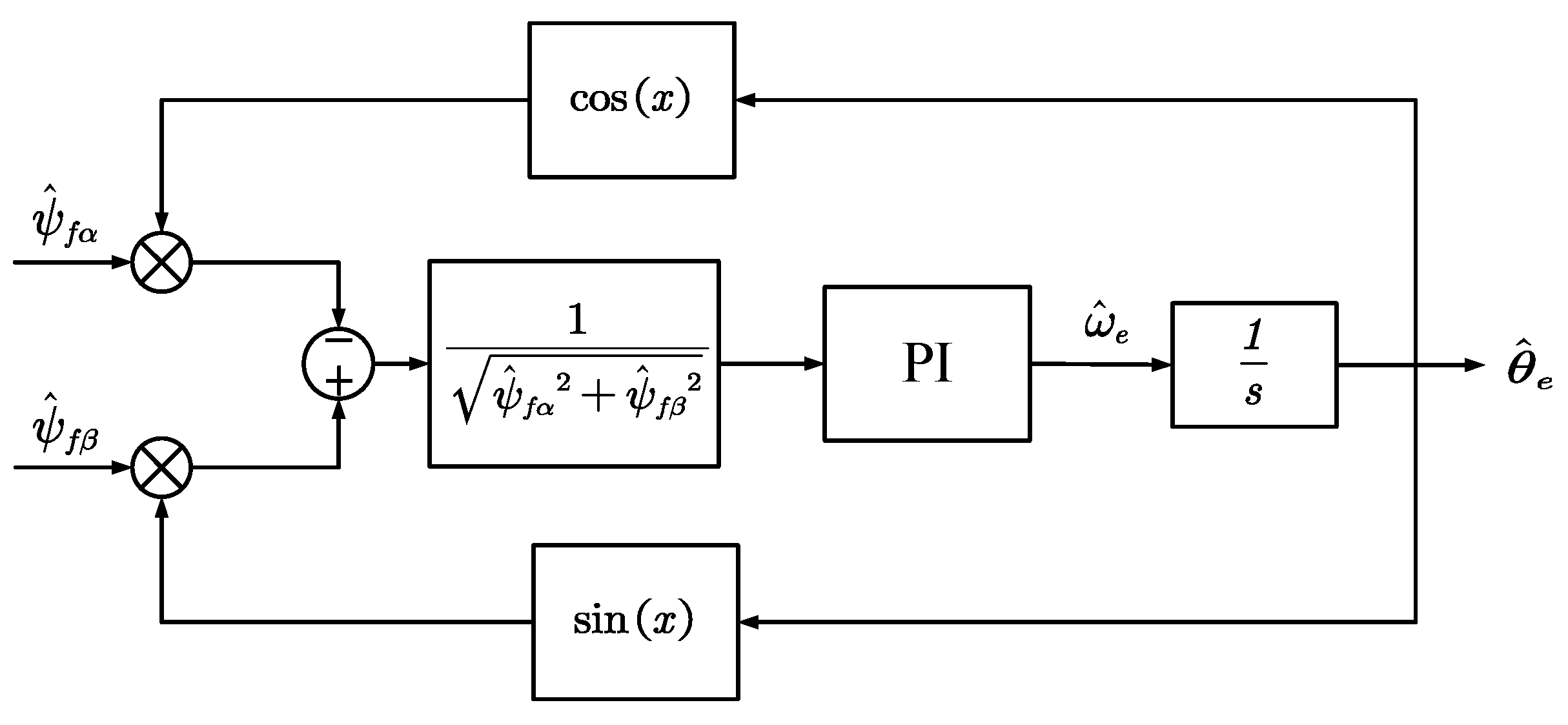
The quadrature phase-locked loop method is used to obtain the motor rotor position angle. The principle of the phase-locked loop method involves demodulating the obtained rotor magnetic chain into position information to estimate the rotor position:
In the equation, , are the estimated stator flux linkages.
Based on trigonometric identity and the concept of an equivalent infinitesimal, we can conclude that:
Thus, we can derive the position error signal from the nonlinear flux linkage observer as:
As a result, the normalized position error is calculated as:
According to the above formulas, we obtain the block diagram of the normalized PLL principle as
Figure 3:
3. Stability Analysis and Parameter Selection
Based on Equations (18)–(22), the flux linkage error equation is established as follows:
In the equation, , is the difference between the observed flux linkage and the actual flux linkage.
From Equation (1), we have:
By rewriting Equation (27) to Equation (28) and introducing a vector to construct the error equation based on the flux linkage error, we obtain:
Based on Equation (30), the following relationship can be obtained:
By further rewriting the error equation proposed in Equation (29), we obtain:
In the equation, is a scalar factor.
Since the error function of the nonlinear flux linkage observer is a function of
, to simplify the complexity of the time derivative expression, a coefficient
is introduced as follows:
In the equation, is a constant.
Therefore, it is easy to obtain:
Next, when performing stability analysis, according to Lyapunov’s stability criterion, a simple positive definite function V is chosen, and here we take the function:
Then, the derivative of this simple positive definite function is:
According to Equation (35), the derivative of the positive definite function is:
Thus, according to Lyapunov’s stability criterion, to ensure the system’s stability, it must satisfy
and
. The following
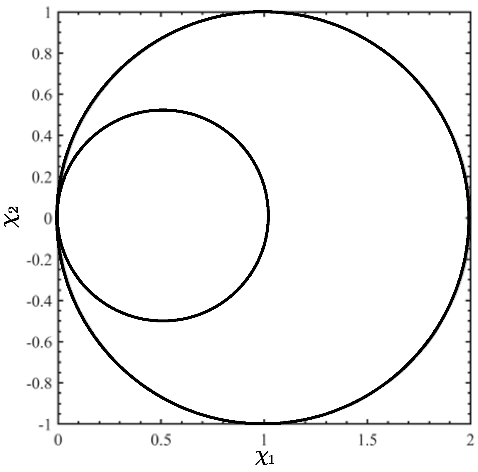
Figure 4 in Cartesian coordinates is drawn based on the above derivative expression:
As shown in
Figure 4, the point set satisfying this constraint condition will not exceed the range of this large circle, that is,
.
Therefore, according to the definition of
:
Within this range, the nonlinear flux linkage observer is globally asymptotically convergent.
Next, when proving the error convergence, assuming
, to make the error derivative approach 0, the following conditions must be satisfied simultaneously:
Obviously, it can be concluded that when , the error can never approach 0.
Then, assuming
, the error convergence situation is analyzed; let
:
That is, under the above constraint conditions, the error converges to 0 only at the origin.
Assuming
, to make the error converge to 0, the following conditions must be satisfied:
Thus, the adjustable parameter
range of the nonlinear flux linkage observer is:
The experimental results show that the best way to select the parameter lambda is through a trial-and-error method.
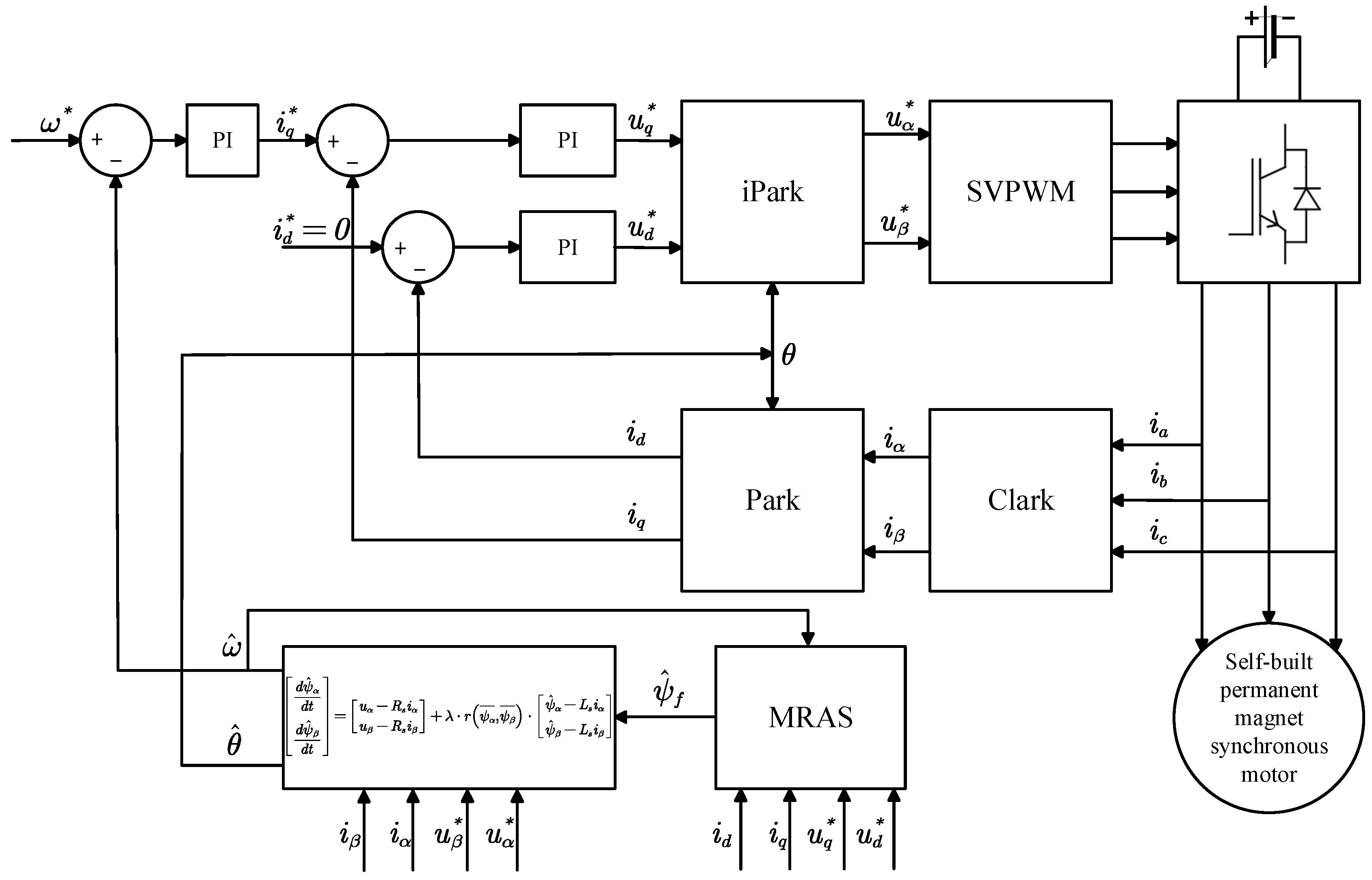
Below is the constructed nonlinear flux linkage observer with the MRAS model block diagram, as shown in
Figure 5:
4. Simulation Analysis
To perform a simulation analysis of the nonlinear flux linkage observer, a Simulink simulation model was constructed, as shown in
Figure 6. This model simulates a scenario where the motor’s flux linkage value changes suddenly during operation, utilizing a surface-mounted PMSM simulation model based on the mathematical representation of the motor in Simulink.
The simulation parameters of the constructed surface-mounted PMSM are detailed in
Table 1.
To verify the control effect of the proposed parameter adaptive nonlinear flux observer, the following experiments were conducted:
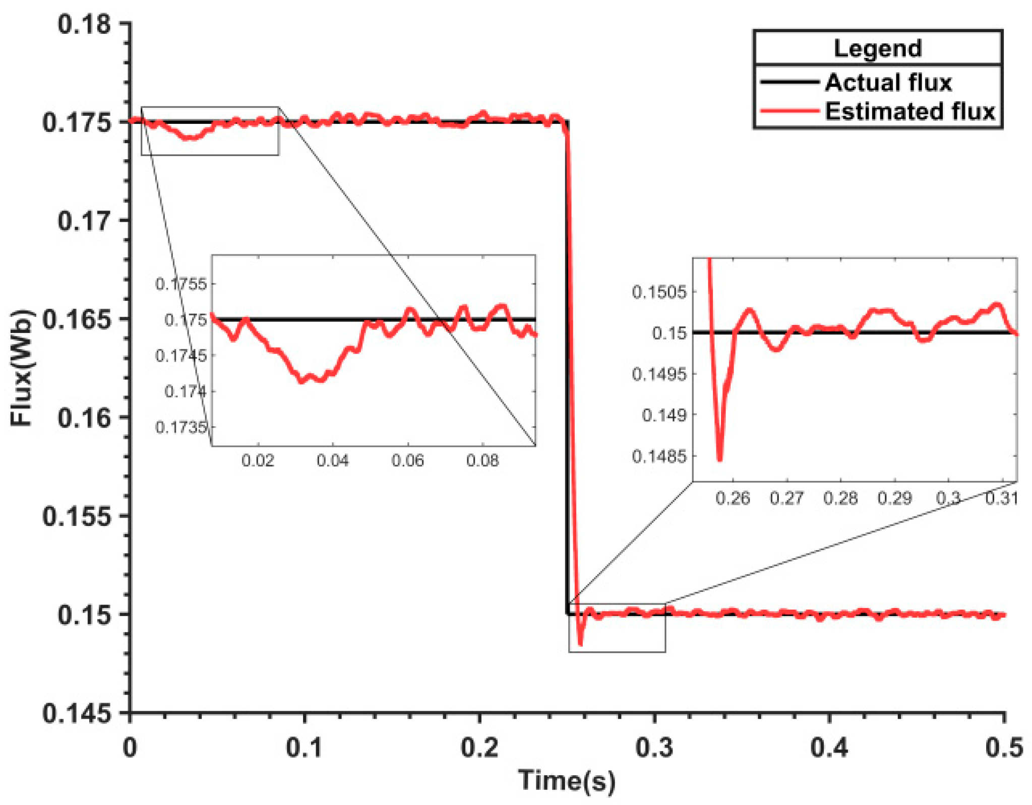
At 0.25 s, the rotor flux linkage of the self-constructed motor was suddenly reduced to 0.15 Wb, and both the nonlinear flux observer and the parameter adaptive flux model were employed for control.
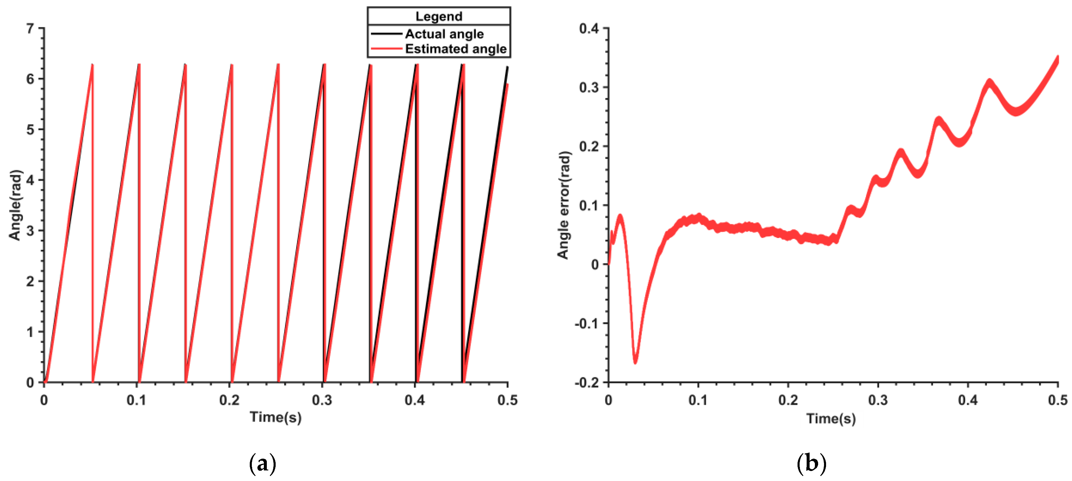
Figure 7 presents the waveform of the estimated electric angle and its error through the utilization of the nonlinear flux observer. It can be observed from
Figure 7b that subsequent to the alteration of the flux value, the estimated angle error gradually enlarges, attaining a maximum of 0.36 rad, and tends to be unstable.
Figure 8 represents the waveform of the electrical angle and its error estimated by the parameter adaptive flux model. It can be observed from
Figure 8b that following the change in the flux value, the maximum angle error is merely 0.18 rad, which is 0.18 rad lower than that of the nonlinear flux model and tends to stabilize.
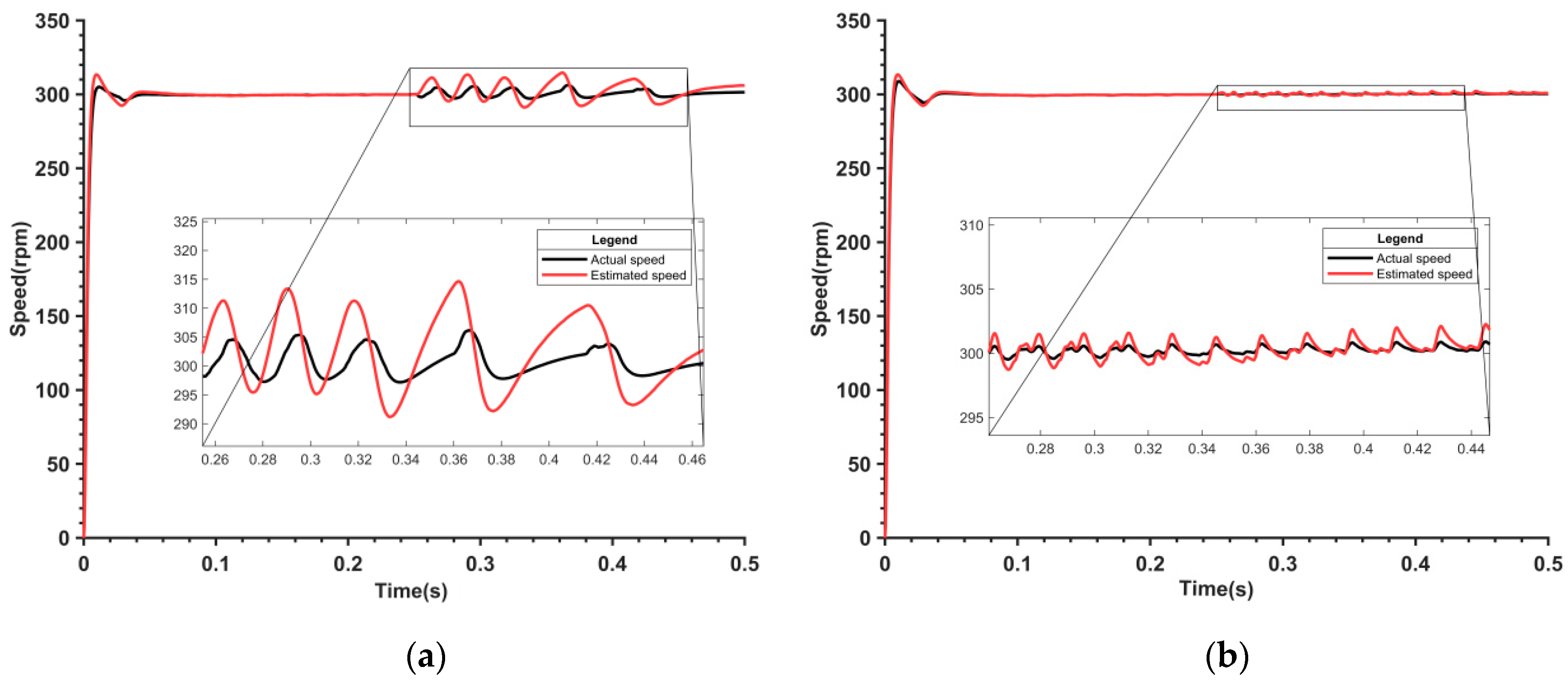
Figure 9 represents the corresponding velocity observation waveform. It can be observed from
Figure 9a that when the nonlinear flux model is employed, the maximum velocity fluctuation amounts to 15 r/min, with an error as high as 5%. It can be noted from
Figure 9b that the speed fluctuation of the parameter adaptive flux model has been significantly enhanced. The maximum is merely 2 r/min, the fluctuation is only 0.4%, and the error has decreased by 4.6% compared with the nonlinear flux model. The estimated speed experiences oscillations because the model needs time to adapt to the new rotor flux linkage value. The rotor flux linkage estimated by the nonlinear flux linkage model does not match the actual value, resulting in significant errors. This leads to inaccuracies in the estimated electrical angle, which in turn causes fluctuations in the estimated speed.
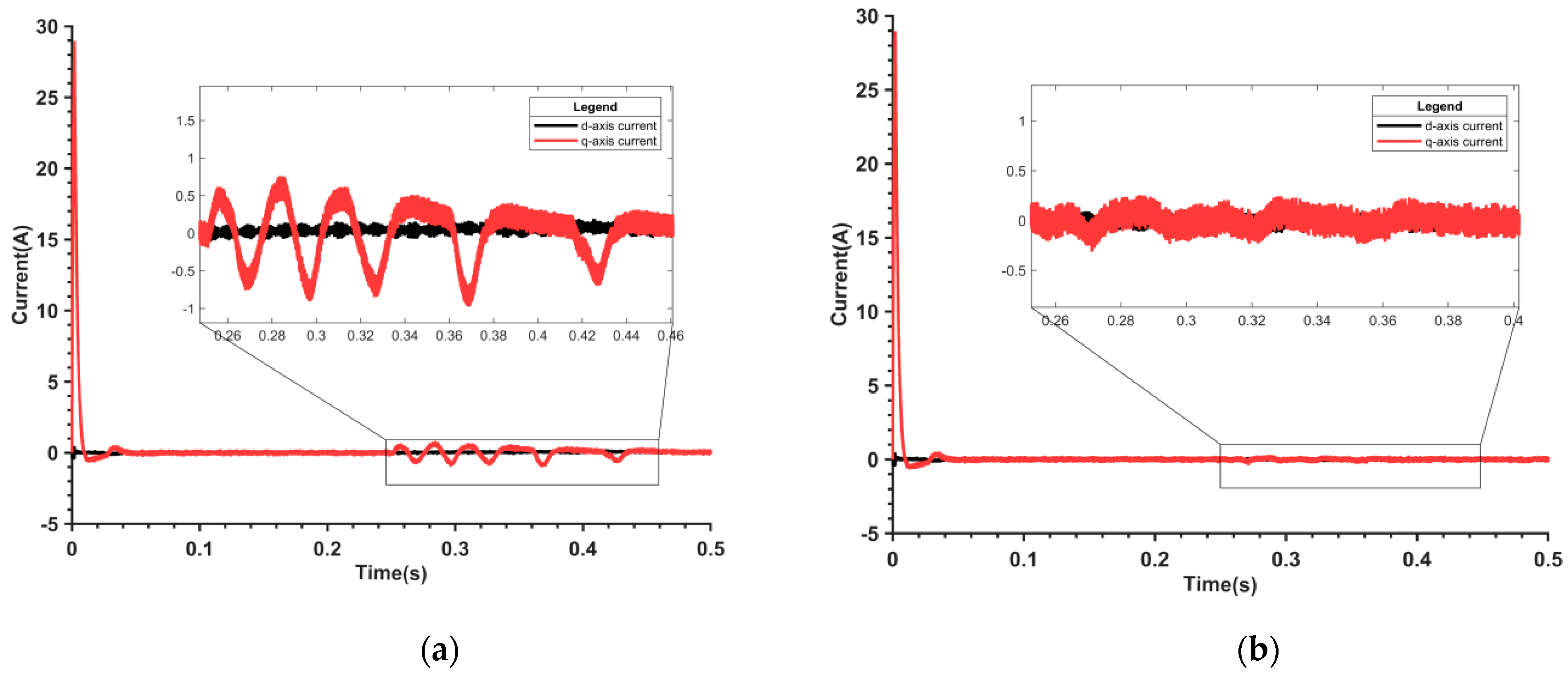
Figure 10 displays the corresponding current observation waveforms. As shown in
Figure 10a, there is a large q-axis current fluctuation using the nonlinear flux model when the motor flux value changes suddenly. From
Figure 10b, the q-axis current fluctuation is significantly reduced when using the parameter adaptive flux model.
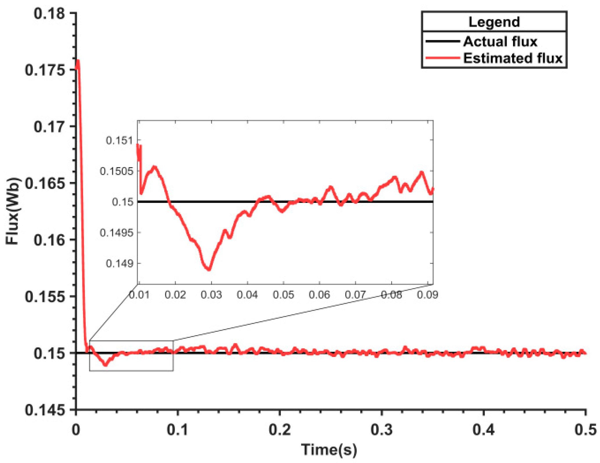
Figure 11 shows the rotor flux linkage value observed by MRAS. There are some fluctuations in tracking when the motor starts or when the rotor flux linkage changes suddenly, but it quickly converges to a stable state.
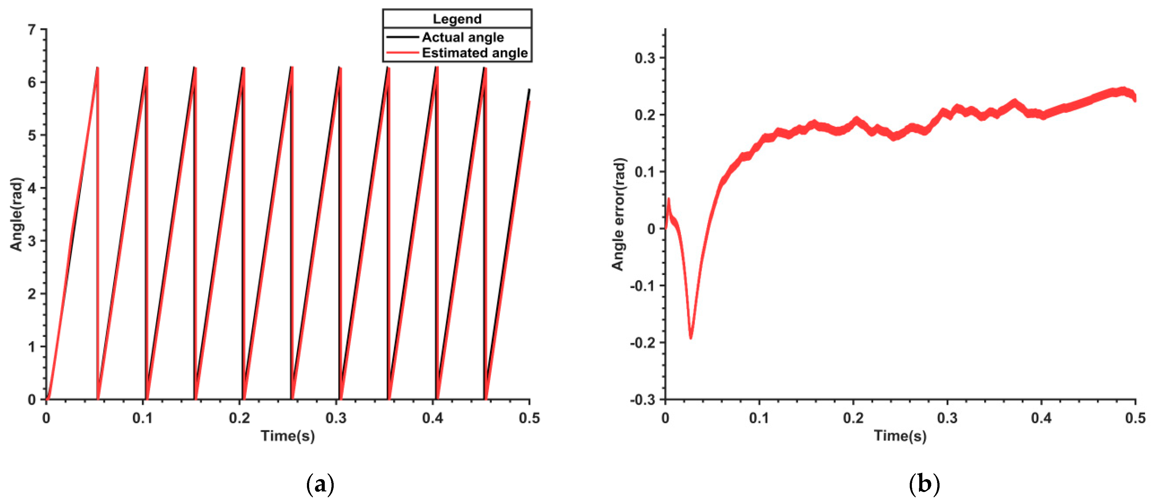
Simulating conditions where parameter inaccuracies are caused by measurement errors, the rotor flux linkage of the self-built motor is initially reduced to 0.15 Wb, and both the nonlinear flux observer and the parameter-adaptive flux model are utilized for control.
Figure 12 shows the electrical angle and its error waveform estimated by the nonlinear flux observer. It can be seen from
Figure 12b that after the motor is started, the estimated angle error gradually becomes larger and keeps rising, with the maximum error reaching 0.25 rad.
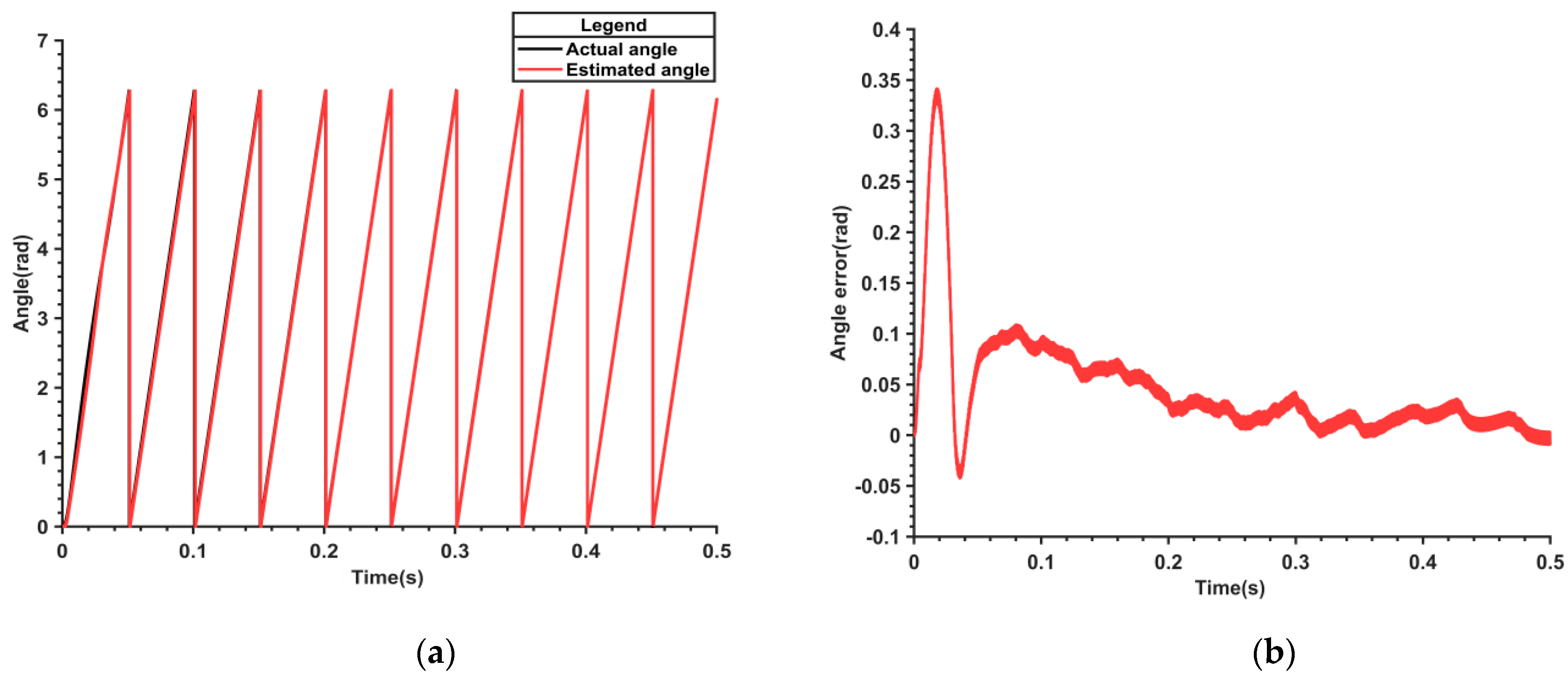
Figure 13 presents the waveform of the electric angle and its error estimated by the parameter-adaptive flux model. From
Figure 13b, it can be observed that the angle error is considerable at the outset, with a maximum of 0.34 rad. However, the angle error reduces to 0.05 rad at 0.15 s, which implies that the parameter-adaptive flux model can rapidly converge to the true angle and handle the angle error caused by the measurement error more effectively.
Figure 14 displays the rotor flux linkage values observed by the MRAS. Initially, there are some fluctuations, peaking at 0.001 Wb, but the system reaches a stable state by 0.05 s, demonstrating that the parameter-adaptive flux model accurately identifies the correct values, even amidst measurement errors.
To verify the robustness of the proposed algorithm, a sudden change in the stator resistance was introduced during operation to observe its effects on the angle and speed estimation.
At 0.25 s, the stator resistance was suddenly increased to twice its rated value. As shown in
Figure 15a, the estimated electrical angle using the proposed algorithm remains accurate. From
Figure 15b, it can be observed that the corresponding estimated speed also demonstrates strong robustness during the abrupt change in stator resistance. This indicates that the proposed algorithm exhibits strong robustness against sudden changes in stator resistance.
5. Experimental Verification
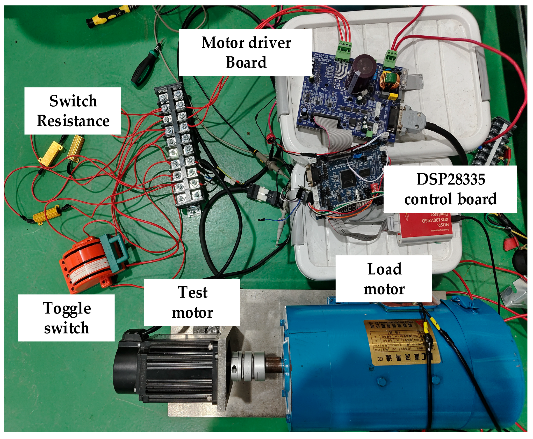
To further verify the effectiveness of the proposed control strategy, an experimental analysis platform for the permanent magnet synchronous motor was constructed, as illustrated in
Figure 16. The TMS320F28335 digital signal processor was employed as the core control chip, with a DC motor as the load motor. The switching resistor was set to 2 ohms, with one end connected to the phase line of the test motor, and the other end connected to the three-phase output of the power board, connected in parallel with a wire. The switch is connected in series with the wire; when the switch is closed, the switching resistor is shorted, and when the switch is open, the switching resistor is connected in series with the three-phase output.
The experimental verification continued to employ the “Id = 0” vector control strategy (FOC). The PWM switching frequency and current sampling frequency were set to 10 kHz. The principal parameters of the experimental motor are detailed in
Table 2.
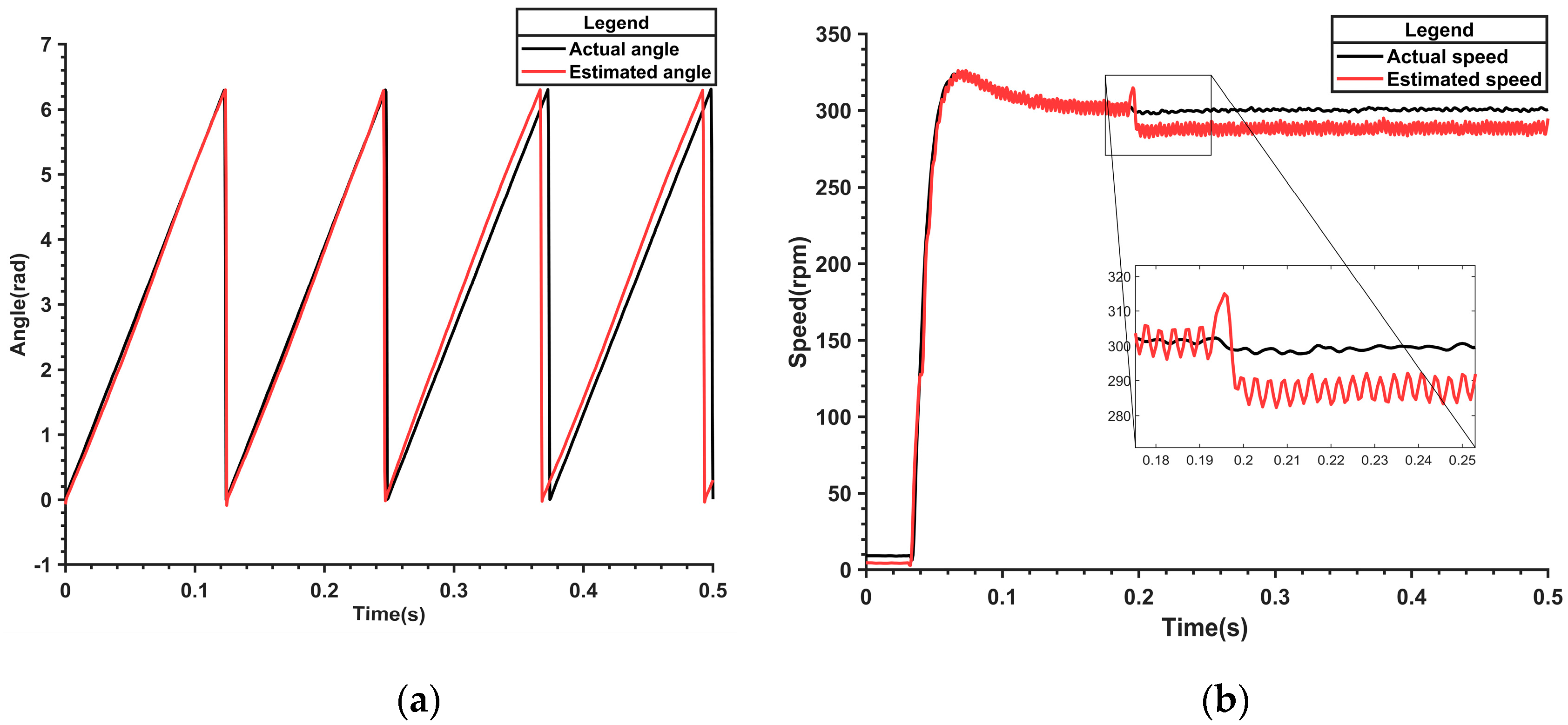
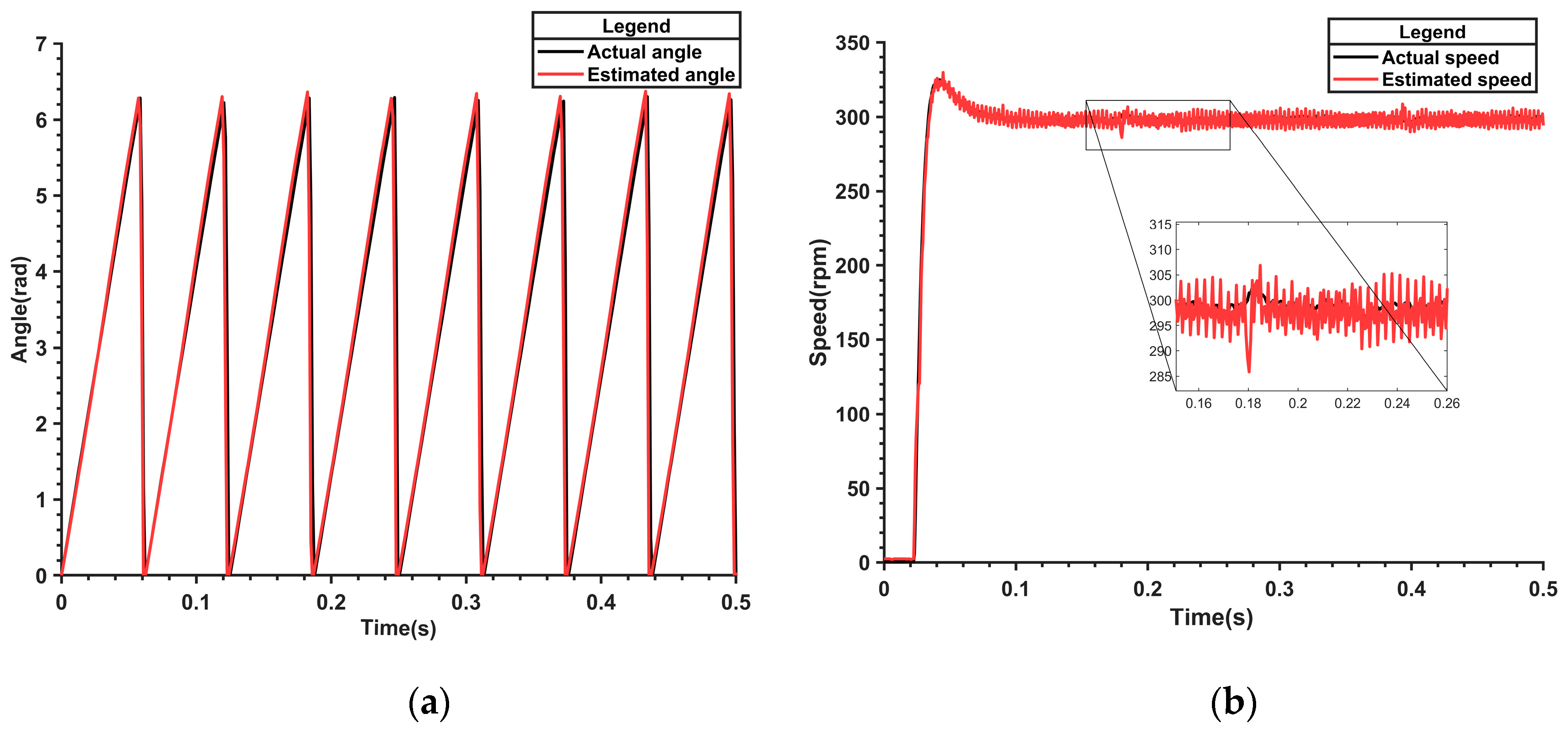
Suddenly changing the flux linkage value in the model during operation can also verify the observed effects of the nonlinear flux linkage model, with the observed angle and speed waveforms shown in
Figure 17.
From
Figure 17a, it can be seen that when the flux linkage value inside the model is suddenly changed at 0.25 s, the estimated angle error increases significantly. From
Figure 17b, it is evident that the speed is also greatly affected after the sudden change in flux linkage value. The speed first experiences a large fluctuation and then gradually stabilizes around 290 r/min, with a significant error compared to the given speed. This indicates that the nonlinear flux linkage model’s estimation performance deteriorates when there is a sudden change in motor parameters or when the parameters are incorrect.
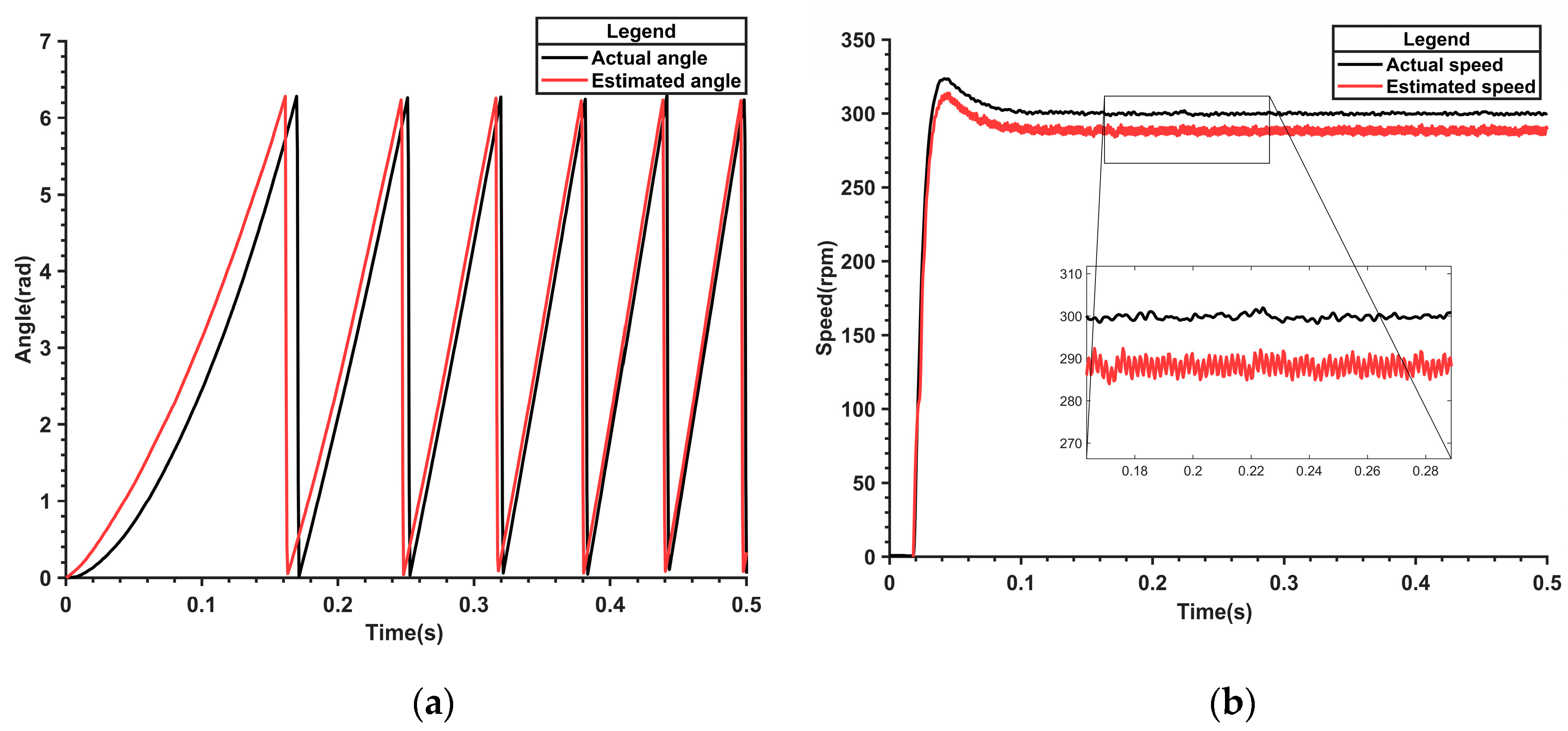
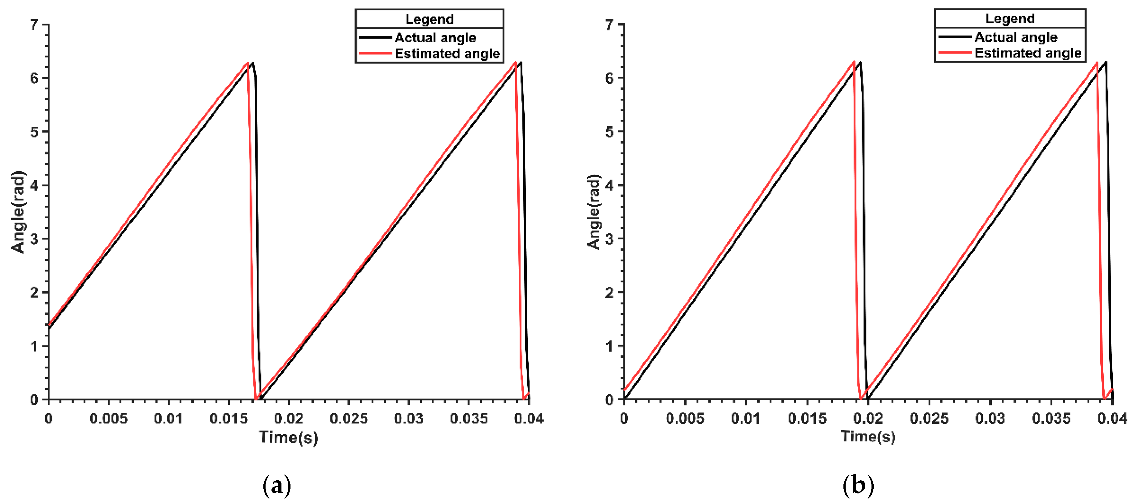
At the beginning, an incorrect flux linkage value is given to the model, and the nonlinear flux linkage model is used to observe the motor’s electrical angle and speed. The experimental results are shown in
Figure 18.
From
Figure 18a, it can be seen that when the flux linkage value does not match the actual value from the beginning, the estimated electrical angle error is significant.
Figure 18b shows that the corresponding estimated speed is also incorrect, consistently having a certain error compared to the actual speed. This further indicates that the nonlinear flux linkage model alone cannot handle situations where the flux linkage value does not correspond to the actual value.
To verify the robustness of the model reference adaptive system combined with the nonlinear flux linkage model against other parameter changes, the stator resistance value was suddenly changed during operation. The comparison between the predicted electrical angle and speed waveforms from the model and the actual values is observed. The experimental results are shown in
Figure 19.
At 0.05 s, the stator resistance suddenly increased to 4.875 ohms. As can be seen from
Figure 19a, there was a slight fluctuation in the estimated angle, but the estimated value was almost equal to the actual value. As can be seen from
Figure 19b, the estimated speed is very good and consistent with the actual value. This shows that the proposed model reference adaptive plus nonlinear flux model algorithm has strong robustness to changes in stator resistance.
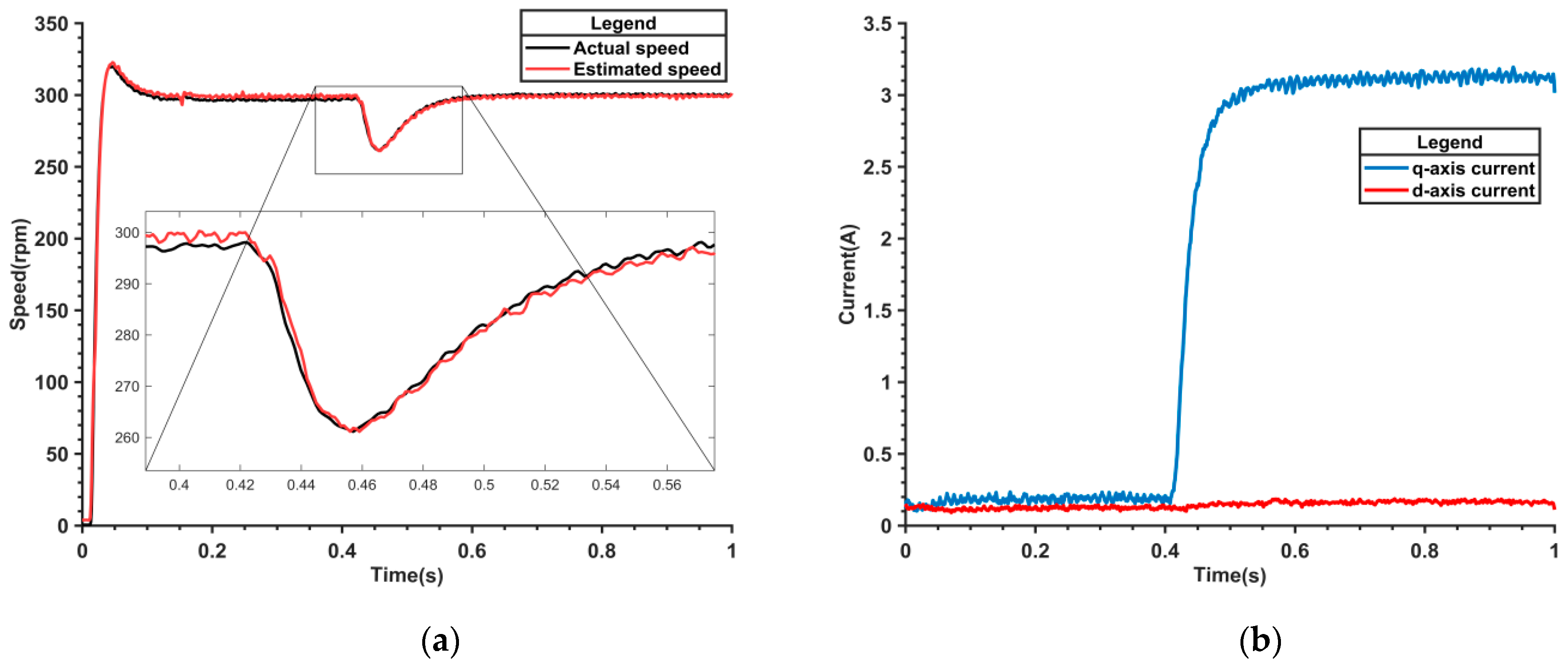
The sudden addition of load torque during operation was conducted to examine the impact of load changes on MRAS rotor flux linkage value identification.
Figure 20a,b exhibit the angle estimation waveforms before and after the sudden imposition of a torque load on the nonlinear flux model, seamlessly integrated with the MRAS system. These figures distinctly demonstrate that the angle estimation error is effectively contained and maintained at a negligible level, even subsequent to the application of the torque load. This controlled response underscores the robust performance of the combined system in ensuring precise angle estimation amidst dynamic load variations.
Figure 21a,b illustrate the speed and current waveforms of the parameter-adaptive flux model before and after the sudden application of torque load.
Figure 21a shows that the speed fluctuates by 38 r/min upon the application of a heavy load but swiftly returns to 300 r/min.
Figure 21b shows a quick response in the q-axis current, reaching 3 A, while the d-axis current remains stable. This confirms the robustness of the parameter-adaptive flux model in managing load changes.
Figure 22 showcases the variation curve of the rotor flux linkage value, as precisely identified by the MRAS system, during the abrupt application of a torque load. Notably, the variation remains minimal at just 0.7%, underscoring the remarkable capability of the proposed MRAS to accurately track and identify flux linkage values even under dynamic and challenging load conditions. This performance underscores the robustness and reliability of the MRAS in ensuring the precise control and stability of the system.
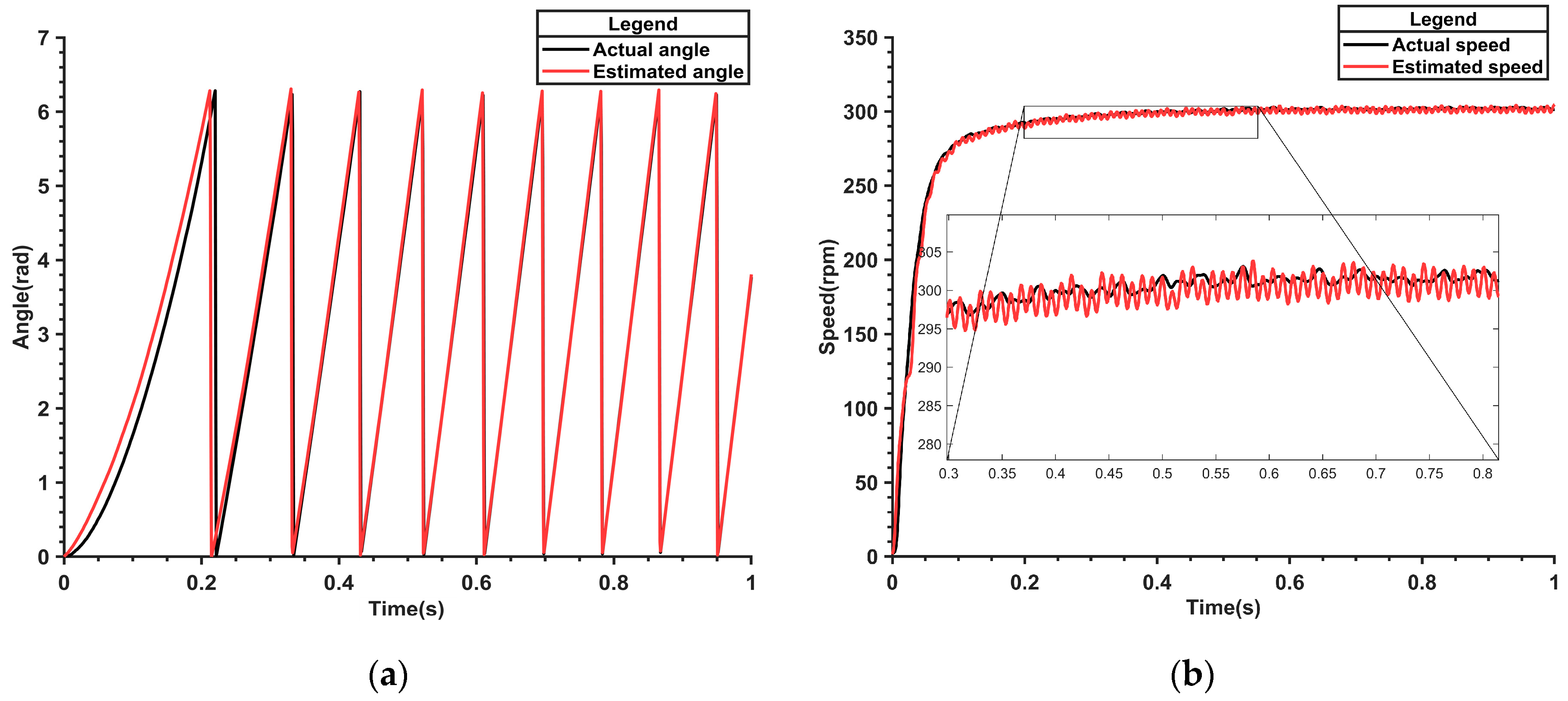
Starting with a load at an initial speed of 300 rpm, we observed the angle and speed waveforms for assessment.
Figure 23a illustrates the angle waveform of the parameter-adaptive flux linkage model. At startup, a noticeable error is evident, but within two electrical angle cycles, the angle converges perfectly to the actual angle, showcasing the model’s rapid adaptation. Meanwhile,
Figure 23b presents the corresponding speed waveform. Although there is a slight error at the beginning, the speed quickly reaches and stabilizes at the specified 300 rpm, emphasizing the system’s ability to maintain accurate speed control. These refined details highlight the effectiveness and accuracy of the parameter-adaptive flux linkage model in real-world applications involving loaded startup conditions.
6. Conclusions
This paper presents the integration of a nonlinear flux observer with a model reference adaptive system (MRAS). Utilizing MRAS to detect real-time changes in motor parameters and incorporating these into the nonlinear flux model significantly mitigates control performance degradation or failure due to parameter shifts. When the rotor flux linkage decreases abruptly from 0.175 Wb to 0.15 Wb, the maximum speed error of the nonlinear flux algorithm is 15 r/min. In contrast, the parameter adaptive flux algorithm limits the speed error to 2 r/min, markedly enhancing dq-axis current stability. With the initial rotor flux linkage set at 0.15 Wb, the angle error in the nonlinear flux model progressively increases, whereas the angle error in the parameter adaptive flux model rapidly diminishes and aligns closely with the actual values. The proposed algorithm effectively handles fluctuations when the stator resistance undergoes sudden changes, demonstrating strong robustness. Moreover, when the rotor flux linkage value in the model is abruptly changed during operation, the angle and speed estimation of the nonlinear flux linkage model significantly deteriorate. This indicates that it is indeed necessary to identify the actual flux linkage value and feed it into the nonlinear flux linkage model. The experiments conclusively demonstrate the robust stability of the combined nonlinear flux algorithm and MRAS control scheme under conditions of both loaded startup and sudden torque application. Upon the abrupt imposition of torque load, the Q-axis current promptly surges and stabilizes at 3 A, while the angle and speed control mechanisms exhibit exemplary performance. Initiating operation with a pre-existing load, the system swiftly attains the preset speed with minimal fluctuations, thereby strongly validating the practicality of the proposed parameter-adaptive flux model. However, given the inherent limitations in replicating real-world scenarios of permanent magnet flux variation during motor operation, our future endeavors will center on simulating this critical operating condition on the dSPACE hardware platform, aiming for even greater realism and precision.
