Article

Dissimilar Resistance Welding of NiTi Microwires for High-Performance SMA Bundle Actuators

1
Intelligent Material Systems Lab, Center for Mechatronics and Automation Technologies—ZeMA gGmbH, 66121 Saarbruecken, Germany
2
Intelligent Material Systems Lab, Department of Systems Engineering, Department of Material Science and Engineering, Saarland University, 66121 Saarbruecken, Germany
3
School of Engineering, University of Applied Sciences Saarbruecken (HTW), 66117 Saarbruecken, Germany
*
Authors to whom correspondence should be addressed.
Actuators 2024, 13(10), 400; https://doi.org/10.3390/act13100400
Submission received: 5 August 2024 / Revised: 13 September 2024 / Accepted: 25 September 2024 / Published: 5 October 2024
(This article belongs to the Section Actuator Materials)

Abstract

:
Shape memory alloys (SMAs) are becoming a more important factor in actuation technology. Due to their unique features, they have the potential to save weight and installation space as well as reduce energy consumption. The system integration of the generally small-diameter NiTi wires is an important cornerstone for the emerging technology. Crimping, a common method for the mechanical and electrical connection of SMA wires, has several drawbacks when it comes to miniaturization and high-force outputs. For high-force applications, for example, multiple SMA wires in parallel are needed to keep actuation frequencies high while scaling up the actuation force. To meet these challenges, the proposed study deals with the development of a resistance-welding process for manufacturing NiTi wire bundles. The wires are welded to a sheet metal substrate, resulting in promising functional properties and high joint strengths. The welding process benefits from low costs, easy-to-control parameters and good automation potential. A method for evaluating the resistance-welding process parameters is presented. With these parameters in place, a manufacturing process for bundled wire actuators is discussed and implemented. The welded joints are examined by peel tests, microscopy and fatigue experiments. The performance of the manufactured bundle actuators is demonstrated by comparison to a single wire with the same accumulated cross-sectional area.

1. Introduction

Shape memory alloys (SMAs) have many beneficial attributes, especially in the form of thin wires made of nickel–titanium (NiTi). Among those are a high energy density, a high actuation frequency, a self-sensing capability and a unique form factor [1,2,3,4]. On the other hand, there are applications that would benefit from SMA technology, with reduced weight and smaller installation space, but requirements like high forces combined with short cycle times cannot be met by usual designs of SMA actuators. As the force scales with the cross-sectional area of the SMA wire, the thermal effects of the volume to surface ratio result in long cooling periods.
Efficient product design requires a small number of parts and simple assembly processes. Of course, this is also true for SMA actuators. The state of the art joining technology for SMA wires is crimping. The crimp itself is an additional part, which needs to be clamped on the wire. Compared to an SMA microwire, the crimp is heavy and large, and it needs to be accessible from at least two sides for assembly. Additionally, high forces are needed to fix the crimp.
For both issues with SMA wire technology there are solutions available. High forces combined with high dynamics are achieved by bundling many small-diameter SMA wires in parallel so that their force output adds up but the volume to surface ratio is consistent [3,5,6]. The difficult crimping process, on the other hand, can be replaced by substance-to-substance bonds like glueing, soldering or welding, where the latter shows most promising results.
The SMA phenomenon in NiTi alloys was discovered in the 1960s, and a lot of research has been conducted on the topic since then [7,8]. Today, NiTi is still the commercially most successful SMA material. Depending on the alloy composition, it behaves either as superelastic or quasiplastic at room temperature. The superelastic alloys are by far the most common and are widely used for medical applications like stents, guidewires, braces and other devices [9]. They can fully recover strains up to 7% [10,11]. Rather new developments based on superelastic alloys are the so-called elastocalorics, where superelastic SMAs are used as solid-state heat pumps [12,13,14,15], and SMA-based stretchable electronics with auxetic structures [16,17]. The titanium-rich, quasiplastic variant of NiTi can be plastically deformed at room temperature by applying a load. When subsequently heated above the phase transformation temperature, however, the deformation of about 5% is fully recovered in conjunction with high-force outputs. Both effects are based on a phase transformation of the crystal lattice structure between austenite (high-temperature phase) and martensite (low-temperature phase), while in superelastic alloys, the martensitic transformation is induced by stress and the transformation between austenite and martensite in actuator applications is thermally induced.
NiTi has a high electrical resistivity that changes significantly depending on the composition of the crystal lattice, the geometry, and the temperature. This effect, called self-sensing, is used to generate a position feedback signal of an SMA actuator by measuring its resistance during operation. SMA microwires (diameter smaller 100 µm) feature cooling times around one second and below under natural convection at air and room temperature; furthermore, their unique form factor allows them to be fitted in tight spatial conditions.
Welding of NiTi and similar alloys is an extensive field of research [18,19]. It is mostly concentrated on the similar and dissimilar laser welding of superelastic material for medical applications, where good results of joint strength and material properties are achieved. Laser welding has also been investigated for NiTi actuator wires down to diameters of 100 µm [20]. It has been shown that joints between NiTi and stainless steel as well as copper are feasible [21,22]. Welded joints of NiTi and stainless steel have been proven to show good mechanical properties. Other welding technologies like electron beam welding, friction stir welding, TIG welding, impact welding and resistance welding have also been investigated [23,24,25]. Published work on resistance welding, however, is not found in great numbers but suggests promising results for micro-dimensions [26,27,28,29]. The previous work of Scholtes et al. suggests that NiTi actuator wires with diameters between 100 µm and 25 µm can be welded to stainless steel sheet metal by spot welding, keeping 80 to 90% of the material’s break load [30].
This research article discusses the dissimilar resistance spot welding of NiTi wires with 100 µm diameter from an engineering perspective. Most previous research on microwire welding focuses on superelastic alloys and joining two wires for medical applications or welding a single wire to a substrate. This work concentrates on joining NiTi actuator microwires to a suitable substrate for manufacturing a bundle actuator having high-force output and dynamics. The main targets are high joint break loads, good fatigue life and the development of an automatable and cost-efficient welding and bundling process. A detailed microstructural investigation of the samples is not part of this work. Welding parameters are evaluated by pull-off tests as well as peel tests. The welded samples also undergo an actuation fatigue test. The discussed welding process is faster, cheaper and more durable than the commonly used methods to join NiTi wires. Due to the easy-to-control parameters, the process is automatable, and wire bundles with small dimensions and few individual parts can be manufactured.
SMA wire bundles are investigated due to the need to achieve high actuation frequencies while also scaling up the force [3,31,32]. Bundling large-diameter wires enables high force outputs of several kilonewtons, which is otherwise only possible by using SMA rods or bars [5,33]. These bundles are typically manufactured by clamping and wrapping, which usually comes with the disadvantages of many individual parts, relatively large clamp sizes and inconsistent electrical connections of the single wires. Welded bundles, however, need only two substrates for the wires to be joined to. If these are sheet metal parts, the bundles are very flat and feature an ideal installation space. However, they are not restricted to that formfactor, and SMA wire bundles based on a tubular or rectangular design are also possible. With these new bundles, systems with better performance, which means higher force output with fast cycle times, can be realized. The fields of applications for SMA actuators are broadened.
The rest of the article is split into three sections followed by a conclusion with an outlook. Section 2 covers the setup of the welding machine and the experimental methods to evaluate the welding parameters. In the first part of Section 3, the results of the parameter studies are discussed and complemented by actuation and fatigue tests. The second part of the section deals with the process of manufacturing welded SMA wire bundles and the evaluation of the same by actuation experiments.

2. Materials and Methods

Resistance spot welding is a process where electrical current and pressure are used to join two metallic alloys by melting them together at the point of contact, where a weld nugget is formed [34]. It is commonly used in the automotive industry to join metal sheets of a car body. Compared to laser welding, resistance welding is more cost efficient, and the process is easier to control.
In usual spot-welding applications, two opposing electrodes clamp the workpieces, which makes accessibility from two sides necessary. As it is beneficial from a manufacturing and assembly perspective to perform the joining process from only one side, this work is utilizing a gap-welding machine. As displayed in Figure 1, both electrodes are aligned with a small gap in between them. The lower work piece, in this case a piece of sheet metal, rests on a support, while the upper workpiece, the NiTi wire, is held in place by the pressure of either two electrodes (series or gap welding) or one electrode, while the second electrode contacts the sheet metal (step welding). By passing a current through the workpieces, their interface is heated to melting temperature by the Joule effect. After solidification, the pressure of the electrodes is released.
The generated heat H is calculated by
H = I 2 R t K
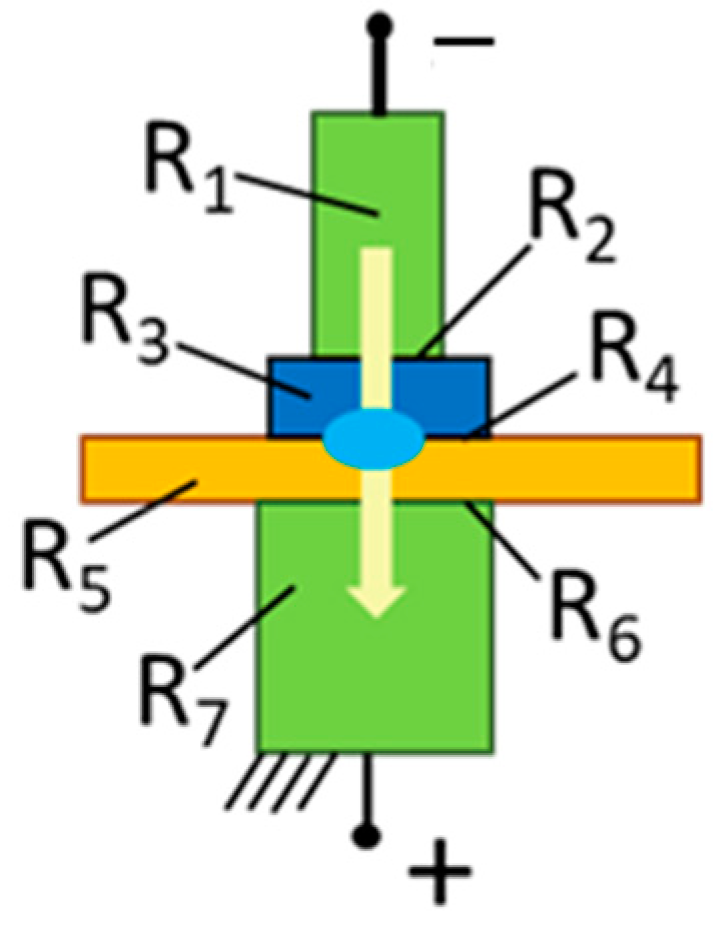
where I is the welding current, R is the overall resistance, t is the welding time and K is a thermal constant that depends on the geometry material and welding force. The resistance is the sum of the individual resistances of the workpieces and the electrodes as well as the contact resistances between them. When studying Figure 2, it can be derived that the highest individual resistance is required at R4, the contact resistance between the weld partners.
The welding machine used in this work is a resistance gap welding head (Unitek, Thin-Line, Monrovia, CA, USA) with spring-loaded electrodes and adjustable force up to 100 N. The spring loading allows the weld head to follow the collapsing of the weldment when melting. The welding transformer Mac Gregor (Mildenhall, UK) DC 1000 supplies a current of up to 1000 A (DC) in a double pulse with adjustable durations of 1 ms to 100 ms and ramp up/down. For all experiments, electrodes made of CuCr1 with a tip area of 0.64 mm2 are used.
The SMA wire used for the experiments is a commercially available SAES Getters (Milan, Italy) SmartFlex NiTi actuator wire with 100 µm diameter and a thin amber-colored oxide layer [35]. For the sheet metal substrate to which the wire is to be welded, a sample geometry of 5 mm × 10 mm with a 3 mm hole is designed. This allows for easy installation and fixation in the welding setup, the testing setups and in possible applications.
From an application perspective, copper and copper alloys are highly interesting as a welding partner for the NiTi wires, as the electrical wiring can be soldered with common methods. Furthermore, the next step with copper alloys could be a direct integration of SMA actuator wires onto PCBs for micro-actuators. However, difficulties with good welding results are expected, as relevant material parameters like electrical and thermal conductivity, displayed in Table 1, differ greatly between NiTi and Cu alloys [36]. While the resistivity of copper alloys is about tenfold smaller than that of NiTi and the thermal conductivity is the same amount larger, SS offers similar parameters compared to NiTi. Differences in those two parameters lead to an unfavorable shift in the resistance and heat distribution of the weld partners. Therefore, good weldability of NiTi to steel is expected. A feasibility study by Scholtes et al. confirms this assumption and presents promising results with SMA wire diameters down to 25 µm [30]. With special flux and solder (e.g., DIN EN 29453 (solder): S-Sn96Ag4 and DIN EN 29454.1, 3.2.2.A (F-SW11) (flux)), copper wires can also be joined to stainless steel with low process temperatures. This enables the integration of steel substrates to circuit boards and in general an easy electrical connection of the welded SMA actuators without using copper alloys as welding partners.
For investigating the resistance welding of NiTi to copper alloys, CuSn6 (DIN 2.1020) and CuZn30 (DIN 2.0265) are used. Alloying with zinc or tin increases the resistivity of copper and reduces the thermal conductivity. The samples have a thickness of 0.4 mm. With X6CrNiMoTi17-12-2 (DIN 1.4571) and X2CrNiMo17-12-2 (DIN 1.4404), two similar steel alloys are used in this study. They both feature particularly good weldability and corrosion resistance, while the 1.4571 is additionally alloyed with a small amount of titanium. The main difference for the experiments lies in the sample thickness (1 mm for 1.4571, 0.3 mm for 1.4404).
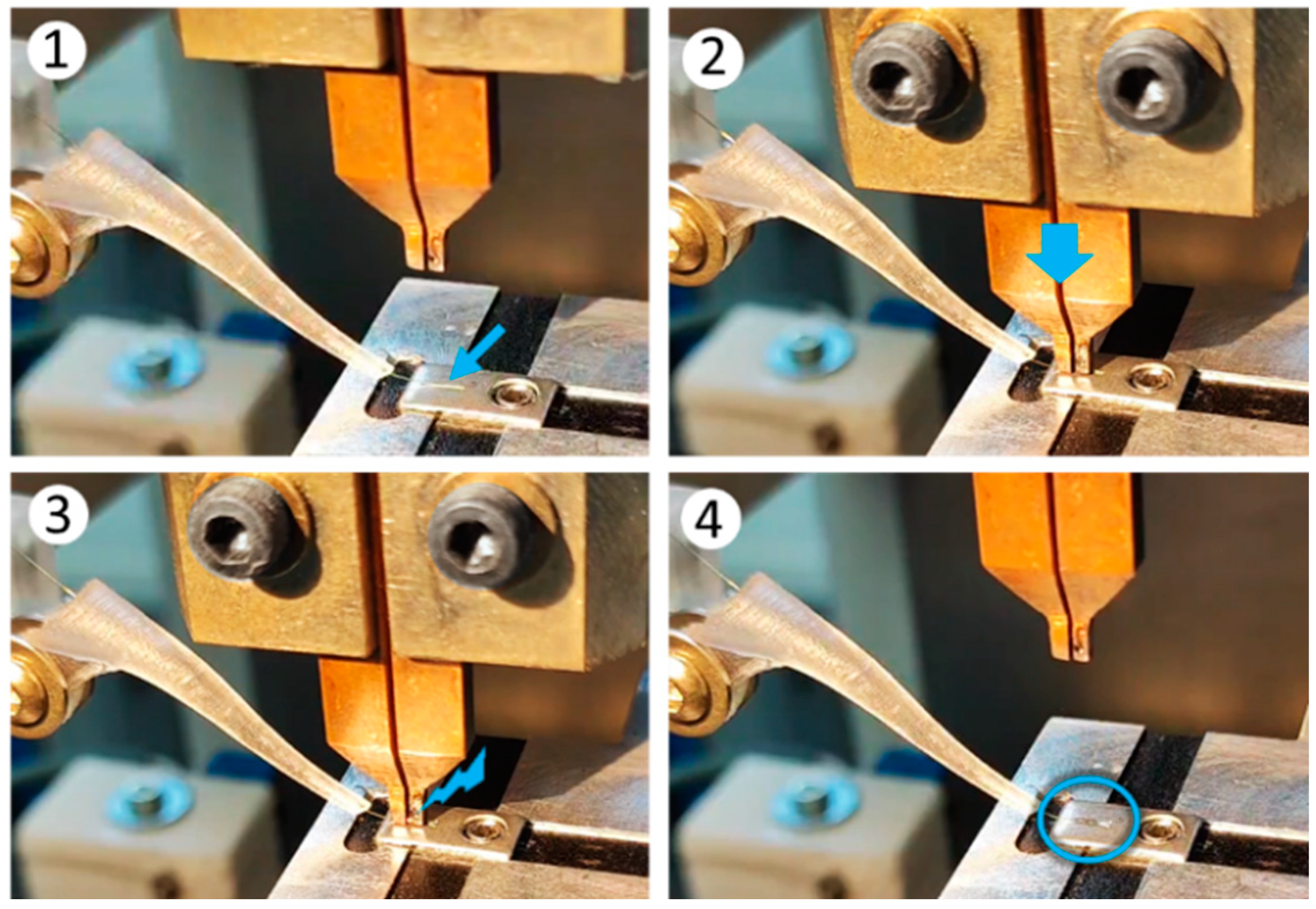
The welding procedure used in this work is displayed in Figure 3 in four steps. The sheet metal sample is positioned in the workpiece holder. The NiTi wire, guided through a small funnel, is placed on top of the welding partner. The weld head with two copper electrodes is moved down, pressing on the wire and sheet metal with 100 N, as is displayed in Figure 3(2). Then, the welding current is run through the weld partner, while the NiTi wire is slack. On close inspection of Figure 3(3), the red-hot metal between the tips of the electrodes is recognizable. After a short cooling time, the weld head is moved upwards, as is depicted on Figure 3(4), and the NiTi wire is joined to the steel sample.
As stated in Equation (1), the influence of the welding current is squared, while the welding time has a linear effect on the generated heat. This work therefore focuses on the variation in the welding current, because it has the greatest influence on the results. The welding time is set to a constant value of two pulses with a 15 ms holding time and an additional 5 ms for ramping up and down. The delay between the pulses is set to 10 ms.
For evaluating the welded samples with pull-off tests, a custom-designed test bench (Figure 4) is used. It is mainly made to measure the break loads and joint strength of the NiTi microwires. Two different pull-off tests are applied to examine the quality of the weld. In a straight pull, the joint is loaded with a shear stress, which corresponds to the load in an actuator application. For a better identification of the best process parameters, a peel test is applied, where the NiTi wire is pulled off under an angle of 45°.
The most promising result is afterwards examined by optical as well as SEM microscopy of microsections and undergoes fatigue testing in cyclic actuator tests. The test setup for fatigue testing is presented by Mayer et al. [41] and can also be used for basic spring-biased SMA actuator characterization. The SMA wire bundles, which are manufactured with the elaborated welding parameters, are built by using an X-Y stage and a stress-controlled installation of the NiTi wires. The actuator characteristics of the high-performance SMA bundles are examined on the same test rig. Therefore, a comparison of force and dynamics with equal-length SMA actuators is carried out. A bundle of four parallel 100 µm NiTi wires is compared to a 200 µm diameter wire. The actuators have the same accumulated cross-sectional area and thus deliver the same force output at equal material stress.

3. Results and Discussion

3.1. Parameter Study: Evaluation and Discussion

The first feasibility tests of resistance welding NiTi wires in various micro-diameters to stainless steel quickly lead to good results [30]. The thermo-mechanical characteristics in a stress–strain diagram show no measurable difference between the welded samples and clamped or crimped samples. It is expected that the welding heat affects the properties of the NiTi in the welding area and leads to brittleness and a loss of shape memory effect in the heat-affected zone. The brittleness is to be expected due to the intermetallic compounds that are formed [29]. This could potentially have a negative influence on the material properties such as strength, transformation strain and fatigue life, among others However, as displayed in Figure 5 on the left, the thermal mass of any wire-mounting element in comparison to a microwire is so large that the SMA does not undergo phase transformation in proximity to the fastener [5]. Due to this uneven heat distribution, welding does not alter the functionality of SMA actuator wires. This also manifests in the actuator tests, where the stroke does not change with the used joining technology (clamping or welding). As illustrated in Figure 5, the heat-affected zone is smaller than the non-activated length at the edges of an SMA microwire.
Welding experiments with the introduced copper alloys are more challenging, and satisfying results are not as easily achieved compared to steel joints. Due to the low resistivity of CuSn6 and CuZn30, the contact resistance between the welding partner and NiTi is similar to the contact resistance to the copper electrodes. This results in unsuccessful welds, where the NiTi wire sticks to the electrodes of the weld head instead of the copper alloy sample. The CuZn30 additionally tends to create an electric arc in the welding process as the zinc evaporates, resulting in unusable welds. The most promising results are achieved with gap welding, where the electrodes only contact the NiTi wire, and welding currents of 400 A. The welded joint strength is significantly weaker than the joints to steel with 300 A, which is display in Figure 6. The straight pull-off tests are conducted with five samples for each test. Because of the reasons discussed previously, more than five welding attempts with the copper alloys are necessary to obtain five usable samples.
The rupture of the NiTi wire usually happens in the heat-affected zone, which is to be expected. The NiTi weld bead stays joined to the sheet metal. However, welded samples with the copper alloys that result in weak joint strengths mostly feature a full separation of the NiTi wire and sheet metal. The welding results with stainless steel are repeatable, consistent and show high pull-off strength levels. The spread in the samples of both already pre-selected copper alloys is four to five times higher than that of steel with about half the average break load. Due to these factors, the investigation is continued with stainless steel samples only.
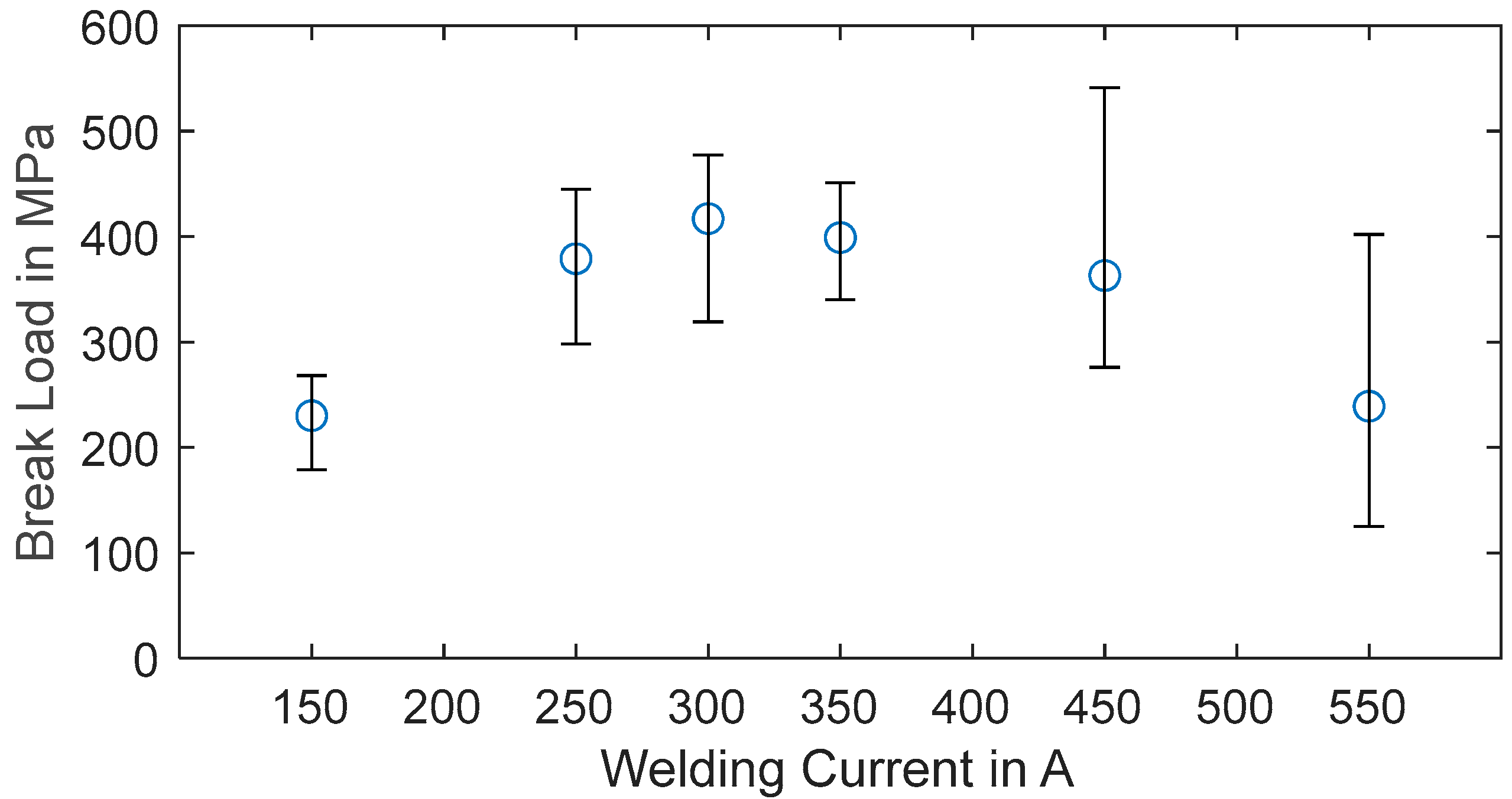
The joint break loads in straight pull-off tests of samples with varied welding currents with NiTi and 1.4571 exhibit values from 1000 MPa to 1200 MPa, and the differences are hardly recognized. Therefore, the parameters for the optimal welding current are evaluated by peel tests, which is a common testing method for resistance-welded sheet metals for car body parts in the automotive industry. The test series starts with a current of 150 A and is increased in 100 A steps up to a welding current of 550 A.
With each current, five samples are manufactured by step welding. The mean values and spreads of the peel test results are displayed in Figure 7. As a sweet spot around 250 A and 350 A is recognizable, a further test series with a 300 A welding current is added. Standard deviation is not displayed. Because of the relatively small number of samples, the spread is more meaningful. The data show a noticeable trend, where the average joint break load of the 300 A welding current is at a maximum with 417 MPa under peel load. Increasing and decreasing the welding current level leads to a drop in the average break load. It can also be determined that the spread of the peel break loads increases with increasing welding current. From the results of the straight pull-off tests, as well as the peel tests, it can be derived that resistance step welding of NiTi wires in micro-diameters to stainless steel sheets is a robust and easy-to-control process. This is promising for the application of an automated process for the manufacturing of SMA wire bundles and the direct wire integration by resistance welding in SMA-driven systems. Compared to laser welding, the proposed resistance welding process is cheaper and easier to control, and the positioning of the wire on the weld partner is simplified. A laser-welding process of NiTi microwires needs an additional fixation for the wire in the weld zone, and a special treatment of the SMA prior to welding can be necessary.
As other parameters are known to influence the weld quality as well, the following additional tests are performed with a 300 A current:
  • Gap welding;
  • Welding with a negative electrode, step welding;
  • Pressure force reduced to 35N, step welding;
  • Sample 1.4404 with 0.3 mm thickness, step welding;
  • Thicker oxide layer on NiTi wire, step welding.
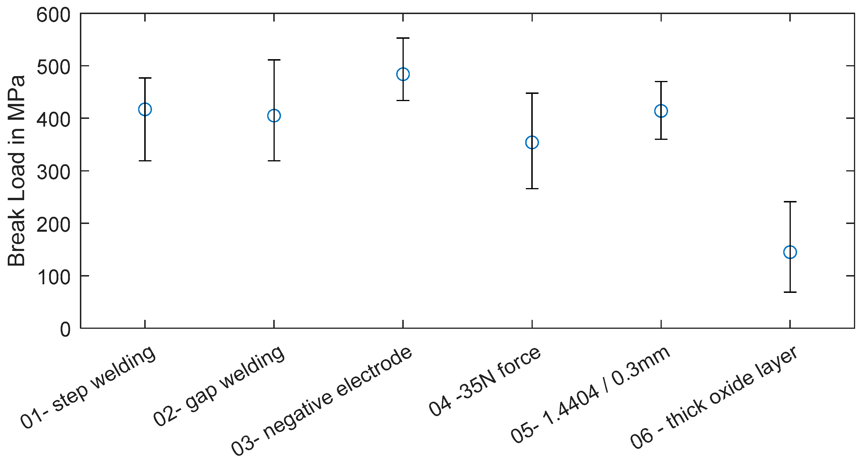
The data of these added tests are displayed in Figure 8, with the 300 A step welding result as a reference value. It is recognizable that changing the welding method to gap welding and a different steel alloy with smaller thickness does not measurably influence the joint break load under peel stress. Reducing the force of the electrodes from 100 N to 35 N results in slightly lower strength.
The Peltier effect is known to influence the formation of the weld bead in resistance welding of small dimensions [41,42]. The heat transfer in the thermoelectric effect occurs with the direction of the current, which is why the negative electrode should be placed on the smaller or thinner weld partner. A positive result on the weld strength by changing the electrode polarity is seen in this study as well. Placing the negative electrode on the NiTi microwire increases the joint break load of the peel tests slightly, as can be read from the data displayed in Figure 8. During the manufacturing of NiTi wires, an oxide layer, mostly consisting of titanium oxide, is formed. Commercially available NiTi actuator wires come with oxide layers of different thicknesses. In general, it can be determined that a darker wire surface corresponds to a thicker oxide layer.
As the oxide layer is expected to influence the contact resistance in a negative way, the tests in this study are performed with a wire having a thin oxide layer. To compare both versions, in Figure 8 the peel tests results of a 100 µm wire with a thick dark oxide layer are displayed. The joint break load is significantly decreased. This indicates that the oxide layer must be reduced or removed for proper resistance welding strength. The experimental parameter identification for a dissimilar resistance welding process results in a robust parameter set. With 300 A, a 100 µm NiTi wire with a thin (amber colored) oxide layer can be welded to SS substrates with high joint strength and good repeatability. The exact steel alloy and thickness and the electrode configuration have only minor influences on the results. Common actuator applications work with up to 200 MPa of material stress, which corresponds to a safety factor of over five when the wire is not loaded under an angle.
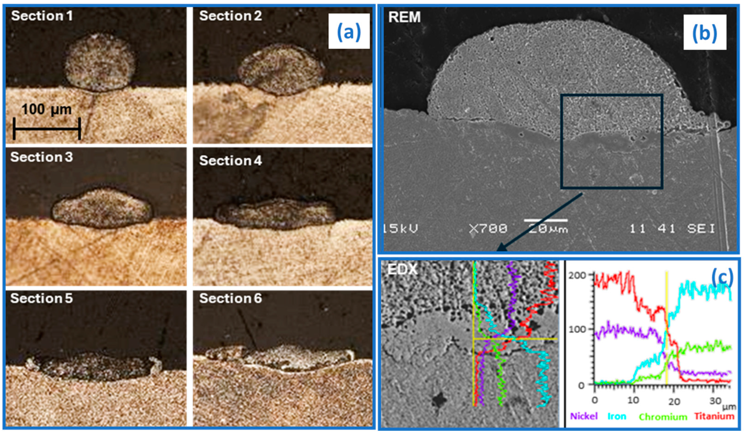
For further investigations, microsections of the weld bead are prepared and microscopically examined. The sample is embedded in resin and cut down to where the weld bead begins. After that, the sample is basically sliced, and microsections are prepared approximately every 100 µm. The sections of the weld bead are etched and examined with optical microscopy, and the fusion zone is investigated by SEM and EDS, of which the results are displayed in Figure 9. The radial cuts through the NiTi wire on the left side in Figure 9 show the deformation of the NiTi under the influence of welding heat and pressure. The wire is flattened out and is pushed into the steel, which also softens due to the welding heat. Resistance welding can join two materials by a solid-state bond as well as a fusion bond. The first is known to show little strength under peel loads and can be identified by a clear separating line in microscopical images. Additional to the high peel strength, Figure 9a–c suggest that a fusion bond is evident. Based on the SEM (see Figure 9b) and the added EDS of a microsection of a sample with the same welding parameters, the fusion bond can be verified. A transition zone between the NiTi and 1.4571 steel is visible. The data of a line in the EDS through this zone, displayed in Figure 9c, shows a gradual distribution of the main alloying elements of the two joining partners. This suggests a melting of steel and NiTi in the welding area resulting in a strong fusion bond.
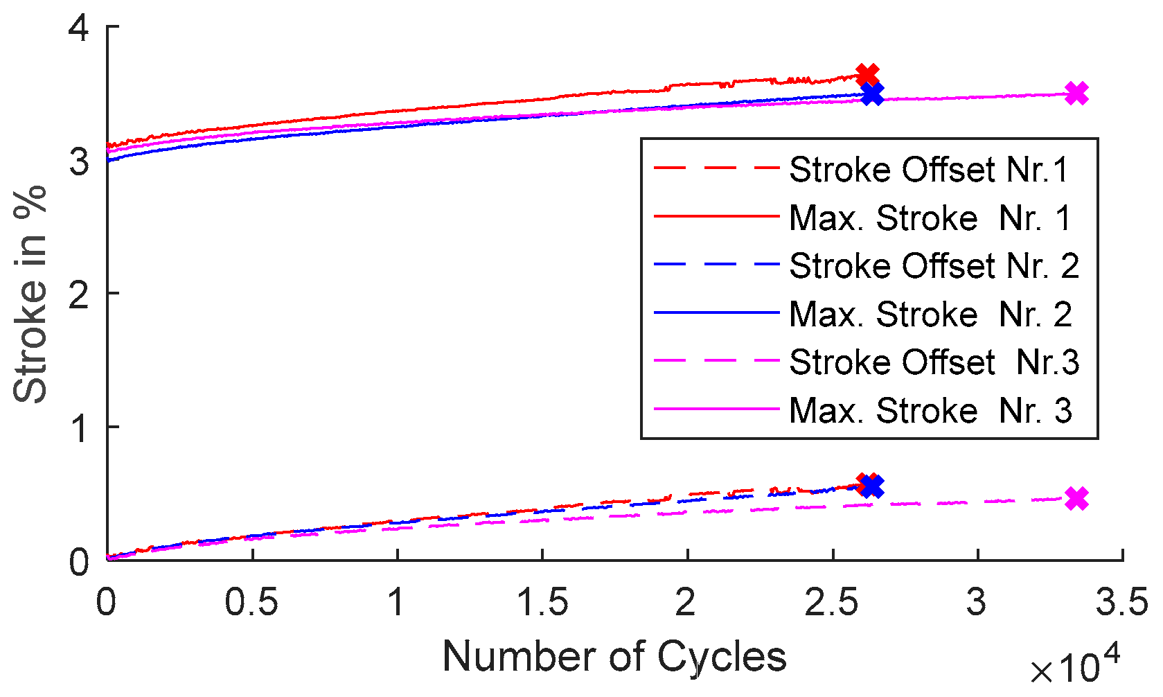
For fatigue tests with the elaborated parameters, three samples with a 70 mm SMA wire welded on both ends to 1.4404 sheet metal are manufactured. The NiTi wire is welded on one side via step welding with the positive electrode, and the opposite side is joined to the steel by step welding with the negative electrode towards the load. This is because of the design of the setup of the welding machine and the workpiece holder on an X-Y stage, which is also explained in the following section. Each sample is installed on a lifetime test bench for fatigue testing detailed by Mayer et al. [43]. An in-depth discussion of the test bench including sketches and pictures can be found in the dedicated publication. The layout of the setup is horizontal and consists of three identical measurement stages aligned beside each other. The SMA actuators are biased with a tension spring. For each activation cycle, the maximum and minimum values for stroke as well as force are recorded. The samples are preloaded with 300 MPa (2.35 N) and heated with an electrical current of 300 mA until 3% of stroke is reached, which leads to increase in stress due to the spring characteristic of 400 MPa (3.14 N). After the specified stroke is reached, the samples cool for 3 s. The activation is repeated until failure of the sample. The results of the fatigue tests are illustrated in Figure 10, where the evolution of the stroke over the cycles is displayed. This behavior is typical for the high stress actuation of SMA wires. The failure of all three samples was due to breaking of the wire in 30% to 50% of the wire length from the weld spot. Sample Nr. 1 failed after 26,208 cycles, sample Nr. 2 after 26,362 cycles and sample Nr. 3 after 33,407 cycles.
The slight differences in stroke are due to differences in friction in the test setups as well as deviations in spring stiffness and pretension of up to 5%.
The results indicate that resistance welding does not affect the fatigue strength of NiTi actuator wires in a negative way. With the joint strength under a straight pull of 80% to 90% of the NiTi break load and fatigue strength in the same region as unwelded SMA wires, the welding process is a promising joining technology for actuator applications. Because of the material-to-material bond, the electrical connection is superior to clamping or crimping, which can lead to enhancement of the resistance signal quality for self-sensing applications. Derived from the proposed results, a large process window is at hand. While an optimum can be shown, the welding current can be set in a rage of 250 A to 350 A with different weld partners, electrode configurations and polarities. With the exception of thick oxide layers on the NiTi wire, sufficient weld strength is always achieved.

3.2. Welded SMA Bundle Actuators

To scale the force of an SMA actuator wire, the straightforward method is to increase the wire diameter. However, this measure reduces the dynamics of the actuator drastically because the cooling time increases. The cyclic dynamics of actuators is crucial for many applications. Therefore, installing several thin NiTi wires mechanically in parallel is beneficial. To allow air convection between the single wires, a determined distance between the wires needs to be set.
In this work, flat wire bundles, as displayed in Figure 11, are designed and manufactured. They feature installation space for up to seven microwires at a width of 5 mm. This results in a force output of 11 N at 200 MPa combined with short cooling times. The manufacturing process is based on an X-Y stage with two workpiece carriers for the sheet metal substrates. The stage is positioned under the resistance weld head. The adjustable distance between both carriers defines the length of the actuator bundle. The NiTi wire is guided from the reel through a funnel (see Figure 3) and positioned on a specified spot on the steel substrate. After the SMA wire is welded to the first piece of sheet metal, the workpiece holders move sideways and pull wire through the funnel from the reel until the second piece of sheet metal is positioned under the weld head. The wire length is set with a defined prestress, which is then released for the welding process. After the wire is attached on both ends, it is cut, and the next NiTi wire is placed in a defined distance from the first one. The procedure is repeated until the desired number of parallel wires is attached.
For evaluating the performance of the bundle, actuator tests to compare a bundle to a single wire with a larger diameter are run. A 200 µm diameter wire features the same accumulated cross-sectional area as four 100 µm wires. Therefore, they feature similar force output at the same material stress level. The experiment is run on the same setup as the fatigue tests. Both actuator samples have a length of 70 mm and are biased with the same spring. The samples are prestressed to 4.15 N (130 MPa) and activated via Joule heating with a constant current pulse of 800 mA for a duration of 2 s. The activation is repeated three times with a cooling time of 8 s in between. The experimental data are displayed in Figure 12. Both samples reach a stroke of 4% and a force of 10.8 N (340 MPa). The crucial part of the data is the time response of both samples. While the single wire heats faster than the bundle, it takes distinctively longer to cool. This is due to the difference in the ratio of the surface to cross-sectional area. The bundle dissipates heat faster via natural convection than the 200 µm wire. The single wire resets by 1% after 1.5 s, and the bundle resets by 3.3%. The bundle reaches 95% reset of stroke after 2.3 s, while the 200 µm wire takes 3.7 s. Also, it takes 7 s for the single wire to reach the initial force value, while the bundle takes only about 50% of that time. It can be assumed that the dynamics do not change when adding more wires to the bundle to increase the force output further.
Compared to the manufacturer’s data of a 100 µm SMA wire, the cooling time measured in this experiment is slightly higher [44]. This can be explained by the proximity of the heated wires in the bundle that reduce the heat transfer to the ambient air, as also discussed by Britz et al. [5].
So far, the literature on SMA wire bundles is concentrated on clamped or crimped wires. The welded bundles in this work are more compact, easier to manufacture, need fewer individual parts and prove to be durable as well. Data on welded NiTi bundles with different welding technologies are not yet available. However, the electrode size of the resistance weld head is setting the limits for the distance between the wires, and the manufacturing speed is restricted by the movement of the mechanical parts of the setup. A laser-welding process could be faster and enable to further reduce the installation space. These attributes come with the cost of a more complex and expensive process.
The SMA actuator bundles presented in this work are already used in a variety of different research projects. Scholtes et al. designed different industrial grippers driven by the presented bundles [45,46,47]. The latest version of a gripper driven by SMA bundles with six wires in parallel was awarded “Hardware Winner” of the “CASMART 4th Design Challenge” at the SMST conference in 2021 [48]. Furthermore, Simone et al. used the developed actuator bundles for their design of a bioinspired gripping system, and Pirritano et al. utilized them to drive a small rotary motor [6,49].

4. Conclusions

Resistance welding represents a valid joining technology for NiTi microwires. The presented work demonstrates the feasibility to join the SMA wires to stainless steel as well as copper alloys without negatively influencing the material properties. The welding results to steel are especially promising. The verified fusion bond leads to high pull-off strength as well as high fatigue strength. Also, peel tests prove to be a useful tool for the parameter identification of resistance welding processes for NiTi wire. Cyclic actuation tests show that the fatigue life is not reduced by the welded joints. The welding process itself is robust, as the parameter identification shows. With the help of resistance welding, automated and reliable bundling processes are possible. The designed bundles are compact and flat, while showing high performance compared to single wires. The cooling time is 1.4 s faster than a wire with the same accumulated cross-sectional area. The performance of the bundles has already been successfully verified in a variety of technology demonstrations and prototypes. The results of this work are an important step towards industrial manufacturing of high-performance SMA actuators.
The joining of NiTi wires to copper alloys is an open question for future work. Although a welded joint between the two materials can be established, further research to improve the joint strength is needed. Another field that needs to be examined is the design parameters of NiTi wire bundles. The understanding of the influence of wire distance, wire number and geometrical arrangement on the cooling time is important for a further development of the technology.

Author Contributions

Conceptualization, D.S.; methodology, D.S. and R.-K.Z.; software, D.S.; validation, D.S.; formal analysis, D.S.; investigation, D.S.; resources, D.S.; data curation, D.S.; writing—original draft preparation, D.S.; writing—review and editing, P.M.; visualization, D.S.; supervision, P.M., B.F. and S.S.; project administration, P.M.; funding acquisition, P.M. and R.-K.Z. All authors have read and agreed to the published version of the manuscript.

Funding

This work was funded by the European Regional Development Fund (ERDF) and Saarland Government in the project ProForm.

Data Availability Statement

Data are available upon request.

Conflicts of Interest

The authors declare no conflicts of interest.

References

  1. Janocha, H.; Bonertz, T.; Pappert, G. Unkonventionelle Aktoren: Eine Einführung; Oldenbourg Wissenschaftsverlag: München, Germany, 2013. [Google Scholar]
  2. Prechtl, J.; Seelecke, S.; Motzki, P.; Rizzello, G. Self-Sensing Control of Antagonistic SMA Actuators Based on Resistance-Displacement Hysteresis Compensation. In Proceedings of the ASME 2020 Conference on Smart Materials, Adaptive Structures and Intelligent Systems, SMASIS, Online, 15 September 2020. [Google Scholar] [CrossRef]
  3. Kirsch, S.-M.; Welsch, F.; Bevilacqua, D.; Naso, D.; Seelecke, S.; Rizzello, G.; Motzki, P. SMA Antagonistic-Micro-Wire Bundle: First Measurement Results. In Proceedings of the ASME 2020 Conference on Smart Materials, Adaptive Structures and Intelligent Systems, Online, 15 September 2020. [Google Scholar] [CrossRef]
  4. Williams, E.; Elahinia, M.H. An Automotive SMA Mirror Actuator: Modeling, Design, and Experimental Evaluation. J. Intell. Mater. Syst. Struct. 2008, 19, 1425–1434. [Google Scholar] [CrossRef]
  5. Britz, R.; Motzki, P. Analysis and evaluation of bundled SMA actuator wires. Sens. Actuators A Phys. 2022, 333, 113233. [Google Scholar] [CrossRef]
  6. Simone, F.; Rizzello, G.; Seelecke, S.; Motzki, P. A Soft Five-Fingered Hand Actuated by Shape Memory Alloy Wires: Design, Manufacturing, and Evaluation. Front. Robot. AI 2020, 7, 608841. [Google Scholar] [CrossRef]
  7. Buehler, W.J.; Gilfrich, J.V.; Wiley, R.C. Effect of Low-Temperature Phase Changes on the Mechanical Properties of Alloys near Composition TiNi. J. Appl. Phys. 1963, 34, 1475–1477. [Google Scholar] [CrossRef]
  8. Buehler, W.J.; Wang, F.E. A summary of recent research on the nitinol alloys and their potential application in ocean engineering. Ocean Eng. 1968, 1, 105–120. [Google Scholar] [CrossRef]
  9. Duerig, T.; Pelton, A.; Stöckel, D. An overview of nitinol medical applications. Mater. Sci. Eng. A 1999, 273–275, 149–160. [Google Scholar] [CrossRef]
  10. Adler, P.; Yu, W.; Pelton, A.; Zadno, R.; Duerig, T.; Barresi, R. On the tensile and torsional properties of pseudoelastic NiTi. Scr. Met. et Mater. 1990, 24, 943–947. [Google Scholar] [CrossRef]
  11. Lagoudas, D.C. Shape Memory Alloys; Springer: Boston, MA, USA, 2008; Volume 1. [Google Scholar] [CrossRef]
  12. Wang, S.; Shi, Y.; Li, Y.; Lin, H.; Fan, K.; Teng, X. Solid-state refrigeration of shape memory alloy-based elastocaloric materials: A review focusing on preparation methods, properties and development. Renew. Sustain. Energy Rev. 2023, 187, 113762. [Google Scholar] [CrossRef]
  13. Hou, H.; Simsek, E.; Ma, T.; Johnson, N.S.; Qian, S.; Cissé, C.; Stasak, D.; Al Hasan, N.; Zhou, L.; Hwang, Y.; et al. Fatigue-resistant high-performance elastocaloric materials made by additive manufacturing. Science 2019, 366, 1116–1121. [Google Scholar] [CrossRef]
  14. Schmidt, M.; Schütze, A.; Seelecke, S. Scientific test setup for investigation of shape memory alloy based elastocaloric cooling processes. Int. J. Refrig. 2015, 54, 88–97. [Google Scholar] [CrossRef]
  15. Bruederlin, F.; Ossmer, H.; Wendler, F.; Miyazaki, S.; Kohl, M. SMA foil-based elastocaloric cooling: From material behavior to device engineering. J. Phys. D: Appl. Phys. 2017, 50, 424003. [Google Scholar] [CrossRef]
  16. Curtis, S.M.; Gugat, J.L.; Bumke, L.; Dengiz, D.; Seigner, L.; Schmadel, D.; Lazarus, N.S.; Quandt, E. Thin-Film Superelastic Alloys for Stretchable Electronics. Shape Mem. Superelasticity 2023, 9, 35–49. [Google Scholar] [CrossRef]
  17. Dengiz, D.; Goldbeck, H.; Curtis, S.M.; Bumke, L.; Jetter, J.; Quandt, E. Shape Memory Alloy Thin Film Auxetic Structures. Adv. Mater. Technol. 2023, 8, 2201991. [Google Scholar] [CrossRef]
  18. Oliveira, J.; Miranda, R.; Fernandes, F.B. Welding and Joining of NiTi Shape Memory Alloys: A Review. Prog. Mater. Sci. 2017, 88, 412–466. [Google Scholar] [CrossRef]
  19. Kannan, T.D.B.; Ramesh, T.; Sathiya, P. A Review of Similar and Dissimilar Micro-joining of Nitinol. JOM 2016, 68, 1227–1245. [Google Scholar] [CrossRef]
  20. Gugel, H.; Schuermann, A.; Theisen, W. Laser welding of NiTi wires. Mater. Sci. Eng. A 2007, 481–482, 668–671. [Google Scholar] [CrossRef]
  21. Gugel, H.; Theisen, W. Laserstrahlschweißen von Mikrodrähten aus Nickel-Titan-Formgedächtnislegierungen und austenitischem Stahl. Mater. Werkst. 2007, 38, 489–493. [Google Scholar] [CrossRef]
  22. Zeng, Z.; Panton, B.; Oliveira, J.P.; Han, A.; Zhou, Y.N. Dissimilar laser welding of NiTi shape memory alloy and copper. Smart Mater. Struct. 2015, 24, 125036. [Google Scholar] [CrossRef]
  23. Rodrigues, L.F.A.; Amorim, F.A.; Grassi, E.N.D.; dos Santos, P.L.L.; de Araújo, C.J. TIG spot welding applied to NiTi shape memory wires optimized by factorial design. Int. J. Adv. Manuf. Technol. 2022, 121, 7749–7762. [Google Scholar] [CrossRef]
  24. Li, J.; Panton, B.; Mao, Y.; Vivek, A.; Daehn, G. High strength impact welding of NiTi and stainless steel wires. Smart Mater. Struct. 2020, 29, 105023. [Google Scholar] [CrossRef]
  25. Barcellona, A.; Fratini, L.; Palmeri, D.; Maletta, C.; Brandizzi, M. Friction stir processing of Niti shape memory alloy: Microstructural characterization. Int. J. Mater. Form. 2010, 3, 1047–1050. [Google Scholar] [CrossRef]
  26. Tam, B.; Pequegnat, A.; Khan, M.I.; Zhou, Y. Resistance Microwelding of Ti-55.8 wt pct Ni Nitinol Wires and the Effects of Pseudoelasticity. Met. Mater. Trans. A 2012, 43, 2969–2978. [Google Scholar] [CrossRef]
  27. Shamsolhodaei, A.; GhateiKalashami, A.; Safdel, A.; Midawi, A.; Elbestawi, M.; Peng, P.; Zhou, Y. Resistance spot welding of NiTi shape memory alloy sheets: Microstructural evolution and mechanical properties. J. Manuf. Process. 2022, 81, 467–475. [Google Scholar] [CrossRef]
  28. Delobelle, V.; Delobelle, P.; Liu, Y.; Favier, D.; Louche, H. Resistance welding of NiTi shape memory alloy tubes. J. Mech. Work. Technol. 2013, 213, 1139–1145. [Google Scholar] [CrossRef]
  29. Zhang, K.; Shamsolhodaei, A.; Ghatei-Kalashami, A.; Oliveira, J.; Zang, C.; Schell, N.; Li, J.; Midawi, A.; Lopes, J.; Yan, J.; et al. Revealing microstructural evolution and mechanical properties of resistance spot welded NiTi-stainless steel with Ni or Nb interlayer. J. Mater. Sci. Technol. 2024, 180, 160–173. [Google Scholar] [CrossRef]
  30. Scholtes, D.; Zaeh, R.; Schmidt, M.; Motzki, P.; Faupel, B.; Seelecke, S. Resistance Welding of NiTi Actuator Wires. In Proceedings of the ACTUATOR 2018: 16th International Conference on New Actuators, Bremen, Germany, 25–27 June 2018; pp. 500–504. [Google Scholar]
  31. Mosley, M.J.; Mavroidis, C. Design and Control of a Shape Memory Alloy Wire Bundle Actuator. In Proceedings of the ASME 2000 International Design Engineering Technical Conferences and Computers and Information in Engineering Conference, Volume 7B: 26th Biennial Mechanisms and Robotics Conference, Baltimore, MD, USA, 10–13 September 2000; American Society of Mechanical Engineers: New York, NY, USA, 2000; pp. 973–979. [Google Scholar] [CrossRef]
  32. Kratz, R.; Stelzer, M.; von Stryk, O. Macroscopic Sma Wire Bundle Actuator/Sensor System: Design, Measurement, Control Approach. IFAC Proc. Vol. 2006, 39, 1054–1058. [Google Scholar] [CrossRef]
  33. Britz, R.; Welsch, F.; Kirsch, S.M.; Simone, F.; Schmidt, M.; Motzki, P.; Seelecke, S. SMA Wire Bundles—Mechanical and Electrical Concepts. In Proceedings of the ACTUATOR 2018: 16th International Conference on New Actuators, Bremen, Germany, 25–27 June 2018; pp. 1–4. [Google Scholar]
  34. Pfeifer, M. Manufacturing Process Considerations. In Materials Enabled Designs; Elsevier: Amsterdam, The Netherlands, 2009; pp. 115–160. [Google Scholar] [CrossRef]
  35. SAES Group. SmartFlex Springs and Wires. Available online: https://www.saesgetters.com/wp-content/uploads/sites/8/2024/01/SmartFlex-wires.pdf (accessed on 26 September 2024).
  36. Amada Miyachi America. Fundamentals of Small Parts Resistance Welding. Available online: https://www.amadaweldtech.eu/sites/default/files/images/knowlegdebase/AMYA Fundamentals Resistance Welding 03-16.pdf (accessed on 8 March 2024).
  37. Deutsches Kupferinstitut. CuSn6. Available online: https://kupfer.de/wp-content/uploads/2019/11/CuSn6-1.pdf (accessed on 8 March 2024).
  38. Deutsches Kupferinstitut. CuZn30. Available online: https://kupfer.de/wp-content/uploads/2019/11/CuZn30-1.pdf (accessed on 8 March 2024).
  39. Jury, A.; Balandraud, X.; Heller, L. Thermal Conductivity and Specific Heat Capacity of Austenite and Stress-Induced Martensite in Superelastic NiTi at Ambient Temperature. Int. J. Thermophys. 2023, 44, 162. [Google Scholar] [CrossRef]
  40. Scholtes, D.; Seelecke, S.; Motzki, P. Electro-thermo-mechanical characterization of shape memory alloy wires for actuator and sensor applications—Part 1: The effects of training. Eng. Rep. 2024, e12867. [Google Scholar] [CrossRef]
  41. Eagar, T.W. Resistance Welding: A Fast, Inexpensive and Deceptively Simple Process. In Proceedings of the 3rd International Conference on Trends in Welding Research, Gatlinburg, TN, USA, 1–5 June 1992; David, S.A., Vitek, J.M., Eds.; ASM International: Gatlinburg, TN, USA, 1992; pp. 347–351. [Google Scholar]
  42. Deng, L.; Li, Y.; Cai, W.; Haselhuhn, A.S.; Carlson, B.E. Simulating Thermoelectric Effect and Its Impact on Asymmetric Weld Nugget Growth in Aluminum Resistance Spot Welding. J. Manuf. Sci. Eng. 2020, 142, 091001. [Google Scholar] [CrossRef]
  43. Mayer, J.; Molitor, P.; Goergen, Y.; Motzki, P. Design of a Modular Lifespan Test Bench for Shape Memory Alloy Wires. In Proceedings of the ASME 2022 Conference on Smart Materials, Adaptive Structures and Intelligent Systems, Dearborn, MI, USA, 12–14 September 2022. [Google Scholar] [CrossRef]
  44. Saes Getters. SmartFlex® Wire. Available online: www.saesgroup.com (accessed on 17 April 2024).
  45. Scholtes, D.; Seelecke, S.; Rizzello, G.; Motzki, P. Design of a Compliant Industrial Gripper driven by a Bistable Shape Memory Alloy Actuator. In Proceedings of the ASME 2020 Conference on Smart Materials, Adaptive Structures and Intelligent Systems, SMASIS, Online, 15 September 2020. [Google Scholar] [CrossRef]
  46. Scholtes, D.; Seelecke, S.; Motzki, P. Development of a Bistable SMA Actuated Industrial Gripper Based on a Compliant Design. In Proceedings of the ACTUATOR—International Conference and Exhibition on New Actuator Systems and Applications, Online, 17–19 February 2021; pp. 181–184. [Google Scholar]
  47. Scholtes, D.; Seelecke, S.; Motzki, P. Design of a lightweight SMA driven parallel gripper for collaborative robots. In Proceedings of the SPIE Smart Structures and Materials + Nondestructive Evaluation and Health Monitoring, Active and Passive Smart Structures and Integrated Systems XVII, 124830K, Long Beach, CA, USA, 12–16 March 2023; SPIE: Long Beach, CA, USA, 2023. [Google Scholar] [CrossRef]
  48. CASMART 4th Design Challenge. Available online: https://www.casmart.org/home/student-design-challenges/casmart-4th-design-challenge (accessed on 17 April 2024).
  49. Pirritano, C.; Gorges, T.; Britz, R.; Scholtes, D.; Zimmer, L.; Preetz, J.; Goergen, Y.; Motzki, P. Fully Integrated Rotary Motor Based on Antagonistic Shape Memory Alloy Wire Bundles. In Proceedings of the ASME 2023 Conference on Smart Materials, Adaptive Structures and Intelligent Systems, SMASIS, Austin, TX, USA, 11–13 September 2023. [Google Scholar] [CrossRef]
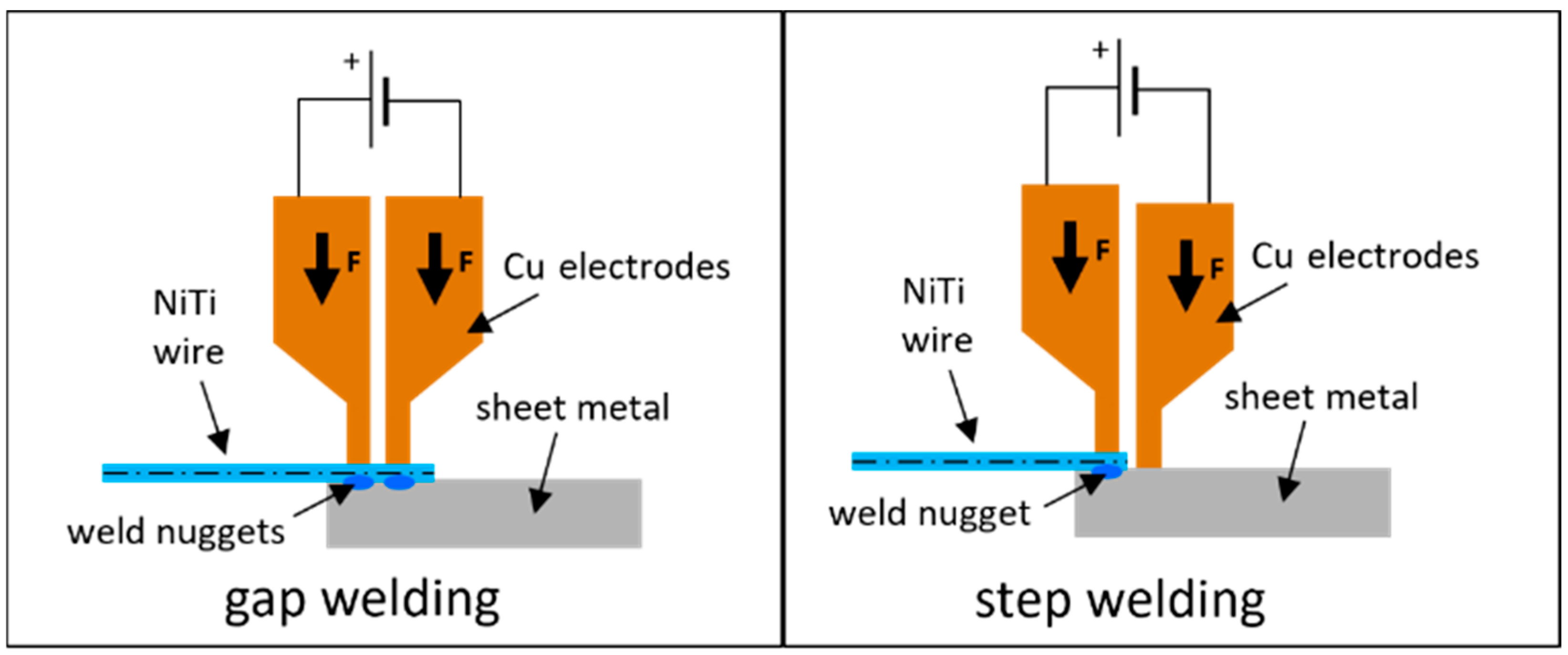
Figure 1. Schematic of resistance gap welding (left) and resistance step welding (right) of NiTi wires to a sheet of metal. Displayed are the two copper-based electrodes, pressing down on the work pieces.
Actuators 13 00400 g001
Figure 2. Schematic of the distribution of the overall resistance in a resistance welding process. R2 R4 and R6 are contact resistances. R1 and R7 are the bulk resistances of the electrodes. R3 and R5 are the bulk resistances of the weld partners.
Actuators 13 00400 g002
Figure 3. Step by step pictures of the resistance welding process: (1) placement of sheet metal sample and NiTi wire under weld head; (2) weld head moved down, applying pressure on SMA wire with both electrodes; (3) welding current is run through workpieces via copper electrodes; (4) weld head is moved up and NiTi wire is joined to steel substrate.
Actuators 13 00400 g003
Figure 4. Picture of the test setup for pull-off and peel tests of the welded samples. The sample clamp is replaceable according to the type of experiment.
Actuators 13 00400 g004
Figure 5. (Left): thermography of a crimped 76 µm NiTi wire, where the influence of the heat sink on the temperature distribution in the activated SMA wire is visible. (Right): the heat-affected zone of a resistance-welded 100 µm NiTi wire to stainless steel is recognized by the tempering colors.
Actuators 13 00400 g005
Figure 6. Comparison of the joint break loads of a 100 µm NiTi wire welded to CuSn6, CuZn30 and stainless steel. The results for average value and the spread of the straight pull-off tests are displayed.
Actuators 13 00400 g006
Figure 7. Average values and spread for the joint break loads achieved by peel tests with 100 µm NiTi wire resistance step welded to 1.4571 steel sheet metal.
Actuators 13 00400 g007
Figure 8. Average values and spreads of joint break loads of peel tests with various parameters and 300 A of welding current.
Actuators 13 00400 g008
Figure 9. Microscopic analysis of resistance-welded NiTi to stainless steel. (a) shows microscopic pictures of samples cut radial to the wire with distances of 100 µm in between. In (b), an SEM picture of a different sample is displayed with the results of an EDS in (c).
Actuators 13 00400 g009
Figure 10. Fatigue test of three samples of 100 µm NiTi wire welded to steel sheet metal. Displayed is the maximum and minimum stroke of each cycle until failure.
Actuators 13 00400 g010
Figure 11. Pictures of a welded SMA wire bundle consisting of five 100 µm wires welded to stainless steel substrates. The upper picture shows a whole bundle with a 105 mm wire length. The bottom picture shows a detailed view of the weld spots.
Actuators 13 00400 g011
Figure 12. Comparison between bundle of four 100 µm wires and a single 200 µm diameter wire. Displayed are force, stroke and current over time of three consecutive actuation tests.
Actuators 13 00400 g012
Table 1. Material parameters relevant for resistance welding of NiTi, stainless steel and copper alloys [37,38,39,40].
NiTiSteelCuSn6CuZn30
Resistivity (20 °C) in Ω·mm2/m0.860.750.110.06
Thermal conductivity (20 °C) in W/m·K101575121
Disclaimer/Publisher’s Note: The statements, opinions and data contained in all publications are solely those of the individual author(s) and contributor(s) and not of MDPI and/or the editor(s). MDPI and/or the editor(s) disclaim responsibility for any injury to people or property resulting from any ideas, methods, instructions or products referred to in the content.