Abstract
The non-variable stiffness of the flexible hinge in the fast-steering mirror (FSM) cannot adapt to varying load demands. To address this issue, this paper presents an innovative variable-stiffness rotational mechanism designed for use with FSMs. Firstly, the working principle of the variable-stiffness mechanism is introduced, and the influence of the length of each structure on the stiffness and the nonlinear influence are analyzed. Then, the variable-stiffness mechanism is applied to the FSM for the variable-stiffness experiment and variable-load experiment. The experimental results show that the variable-stiffness mechanism designed in this paper can realize the change in stiffness. The errors between the experimental value and the theoretical value of the three sets of experiments are +5.72%, +7.57%, and +6.57%. The FSM’s stiffness nonlinearity is very small, and the resonance frequency of the FSM before and after increasing the load can be consistent. The variable-stiffness mechanism can change the frequency characteristics by changing the rotational stiffness of the FSM.
1. Introduction
A photoelectric tracking system is a multidisciplinary technology integrating light, a machine, and electricity; this device is mainly used in photoelectric measurement, astronomical observation, laser communication, and other fields [1,2,3,4]. The composite-axis photoelectric tracking technology is a high-precision tracking control technology used in a photoelectric tracking system. It is mainly divided into coarse tracking and fine tracking. Coarse tracking refers to the preliminary positioning and directional adjustment stage during target tracking. However, as it utilizes a rotating bulky frame to adjust the direction, it comes with disadvantages of high rotational inertia, low precision control, slow response speed, and low bandwidth control. Therefore, it is necessary to incorporate a fast-steering mirror (FSM) within the frame as the fine tracking part, which offers advantages such as low rotational inertia, high control precision, fast response speed, and high control bandwidth [5]. The FSM adjusts the mirror angle by utilizing two mutually perpendicular rotation axes, X-axis and Y-axis, enabling precise control of the beam directed onto the detector.
The “Fast” in FSM can be defined both qualitatively and quantitatively. Qualitatively, ‘Fast’ implies that the mirror exhibits a rapid response speed when adjusting its orientation. Quantitatively, this response speed is reflected in millisecond-level step responses and a high bandwidth. For example, the FSM model OMI201 produced by the Optics In Motion company in the United States has a step response time of less than 5 milliseconds and a control bandwidth exceeding 850 Hz. In practical applications, a faster step response speed implies the capability to track targets more quickly, while a higher bandwidth enables the control of mirror movements at higher frequencies.
The FSM is mainly composed of piezoelectric ceramics [6] or voice-coil motors [7,8] as actuators, and the precise control of the beam is achieved by controlling the rotation angle of the mirror [9]. The rotating mechanism of the FSM is a flexible hinge, and its performance directly determines the overall indicators of the FSM system. The working frequency of the FSM system is high, and the resonant frequency of the system is generally required to be at least 2–3 times the bandwidth of the servo system [10]. Therefore, the resonant frequency of the system is generally required to be high, and the rotational stiffness of the flexure hinge and the mirror load directly determine the resonant frequency of the system. The research studies in [10,11,12] describe that the performance of the FSM is mainly changed by changing the structure of the flexure hinge. The disadvantage of this method is that the stiffness of the flexure hinge cannot be adjusted after its structure is determined. When the FSM increases the load, the resonant frequency of the system will change. Since the stiffness of the flexible hinge cannot be dynamically adjusted at this time, the control system needs to be redesigned to meet the requirements of the resonant frequency. In view of the above problems, this paper designs an innovative variable-stiffness rotation mechanism and applies it to the FSM. The rotational stiffness can change the frequency characteristics of the FSM, which provides favorable conditions for the improvement of mechanical performance and the design of control systems.
The variable-stiffness mechanism can change the rotational stiffness and equilibrium position, improve the safety of human–computer interaction on the robot actuator [13,14], and play an important role in improving the comfort of the robot prosthesis joint [15]. In [16], variable stiffness is realized by changing the position of the spring through the series connection of the stiff actuator and the spring. The disadvantage of this method is that the performance is limited by the bandwidth of the controller, and a lot of energy is consumed to adjust the position of the spring. The research in [17] changed the stiffness and equilibrium position by changing the position of two nonlinear springs by servo motors, but the disadvantage of this method is that friction will occur in the process of using linear springs to realize nonlinear springs. In [18], the stiffness of the flexible hinge is changed by rotating two coaxial flexible hinges. Only the energy is consumed when the stiffness is changed, which greatly reduces the control energy consumption. However, this control method requires high synchronization of multiple motors, the stiffness cannot be adjusted in real time when the flexible hinge is working, and the equilibrium position cannot be adjusted.
The variable-stiffness mechanism is also widely used in the field of vibration isolation [19]. Lifting damping can reduce the resonance peak in the vibration isolation system, but the vibration suppression effect is worse in the frequency range greater than times the resonance frequency of the system. Therefore, lifting damping is not a good vibration isolation method. The minimum vibration frequency that the system can suppress is times the resonance frequency of the system [20], and reducing the stiffness can not only reduce the resonance frequency, but also weaken the resonance peak, so the quasi-zero stiffness system has good low-frequency vibration isolation ability. The studies in [21,22] introduced the application of a quasi-zero-stiffness vibration isolation system in automobile seats and automobile suspensions, which effectively improved the low-frequency vibration isolation ability. The key to achieving quasi-zero stiffness is the design of negative-stiffness mechanisms [23], and the variable-stiffness mechanism happens to provide the solution. The variable-stiffness mechanism is applied to the FSM to form a quasi-zero-stiffness system, which can effectively improve the low-frequency vibration isolation ability of the base vibration while ensuring sufficient bearing capacity.
The nonlinear problem of stiffness is common in variable-stiffness mechanisms. The larger the range of rotation of the mechanism, the more obvious the nonlinearity. The existence of nonlinear factors makes its dynamic response more complex [24]. However, the FSM only needs to achieve precise control in a small angle range. Therefore, the application of the variable-stiffness mechanism to the FSM can effectively avoid the problem of stiffness nonlinearity.
The change of the rotational stiffness of the FSM can not only adapt to the variable load, but also change the frequency characteristics to provide the convenience of optimizing the controlled object for the design of the control system. After the formation of the quasi-zero stiffness system, it can effectively suppress the influence of the low frequency vibration in the moving load platform on the mirror.
For such small rotational systems as FSM, the variable-stiffness mechanism based on a spring has the advantages of convenient design and processing, simple and reliable structure, and the ability to avoid the nonlinear problem caused by large-range displacements. Therefore, this paper proposes a variable-stiffness FSM based on spring components and small-range variable-stiffness characteristics. The contributions and innovations of this paper are as follows:
- 1.
- The torque model is established for the variable-stiffness mechanism based on the spring component, and the influence of the structure dimensions on the torque is analyzed;
- 2.
- It is proposed to use the third-order Taylor series expansion to fit the dimensionless torque to simplify the torque model parameters;
- 3.
- The influence of the nonlinearity of the variable-stiffness model on the frequency characteristics is analyzed by solving the nonlinear dynamic equation;
- 4.
- For the small-range rotating mechanism, experiments are designed to verify the changes in the variable-stiffness and resonant-frequency characteristics of the FSM.
The remaining structure of this paper is organized as follows: Section 2 introduces the establishment and simplification of the variable-stiffness mechanism and torque model and conducts nonlinear dynamic analysis based on the simplified model, Section 3 verifies the variable-stiffness characteristics of the FSM and the influence of nonlinearity, and Section 4 presents the conclusions of this paper.
2. Theoretical Analysis of the Variable-Stiffness Mechanism
2.1. The Mechanism Operating Principle
The schematic diagram of the variable-stiffness mechanism is illustrated in Figure 1. The rotating part comprises two interconnected bars, denoted as a and h, with point O serving as the center of rotation. At both ends of bar a, two springs are hinged, and the other ends of these springs are connected to a movable articulation hinge. The forces generated by the pre-compression or pre-tension of these springs exert torques on the center of rotation O. The rotation stiffness is obtained by derivation of torque to rotation Angle, and different rotation stiffness can be produced when the movable hinge is adjusted to different positions.
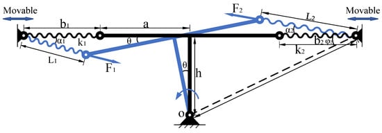
Figure 1.
Schematic of the variable-stiffness mechanism.
The bars a and h are fixed vertically and can rotate around point O. Bar a has springs and hinged at its two ends, with the other ends of these springs are connected to a movable hinge. In the initial position, springs and , both with an original length of , are compressed or extended to lengths and , respectively, and they align with bar a on the same straight line. The lengths and in the initial position can be adjusted through the movable hinge, thereby altering the pre-compression or pre-tension of springs and in their initial positions. When bars a and h rotate by an angle around point O, the lengths of springs and change to and , respectively. The forces exerted by the springs on bar a are and . and create torques at the center of rotation O as follows.
After bars a and h rotate by an angle around point O, the length of spring becomes , and, according to the Law of Cosines, we have
The angle between and the horizontal direction is
Taking the angle opposite to the direction of rotation as positive, the restoring torque exerted by on the center of rotation O is
where .
Similarly, we obtain the torque exerted by on the center of rotation O as
The resultant torque M at the center of rotation O due to and is the sum of and . Upon nondimensionalizing the equation, we obtain
where
2.2. Analysis of the Mechanism Structural Dimensions
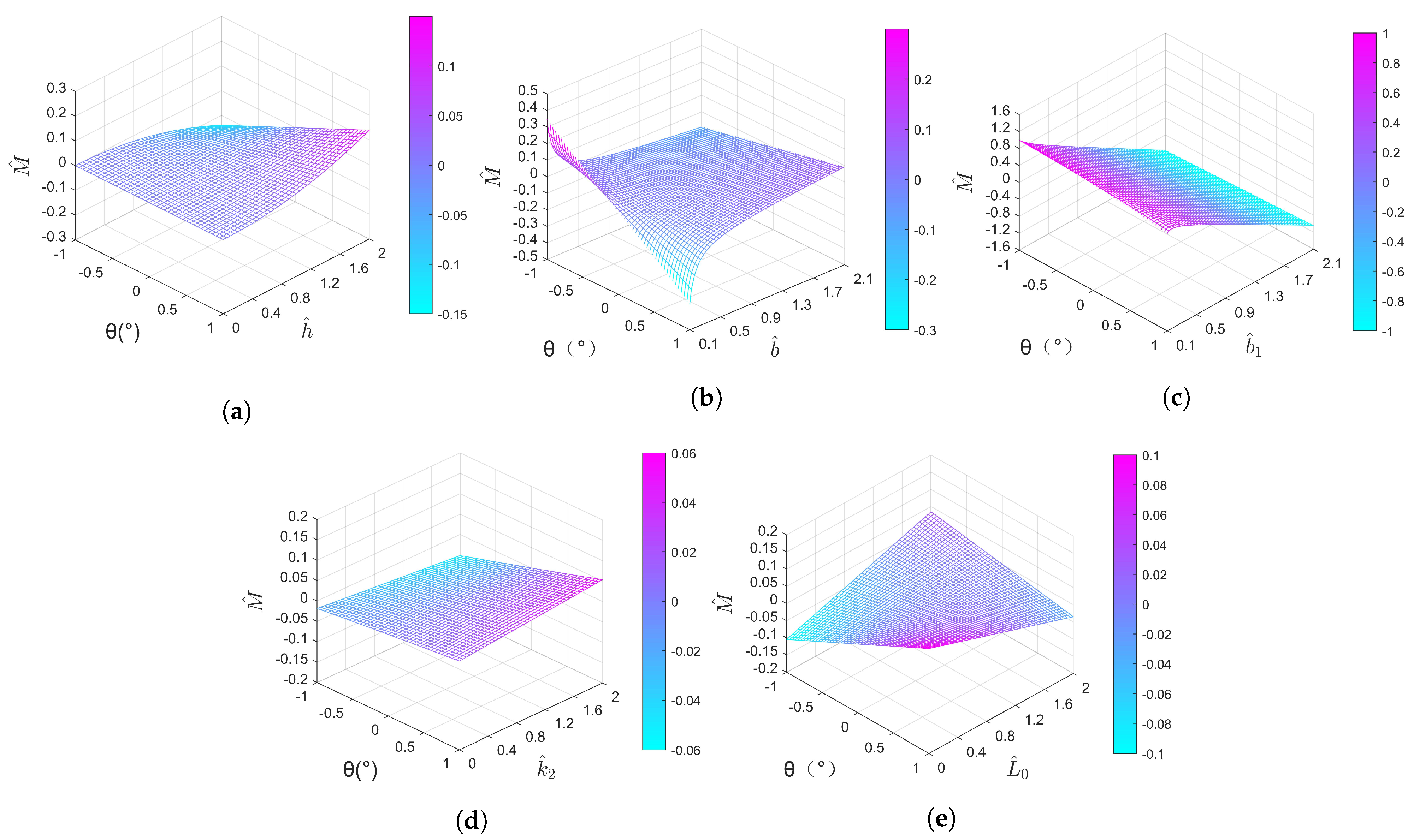
The variable-stiffness mechanism comprises several key structural parameters, including , , , , and . Due to the presence of numerous structural parameters, studying the effects of each dimension on mechanism torque and stiffness can provide valuable insights for mechanism design. Using the control variable method, the impact of various structural parameters on mechanism torque and stiffness was analyzed. The results are depicted in Figure 2; the first derivative of the dimensionless torque to the rotation angle is the rotation stiffness, that is, the slope in the – plane.
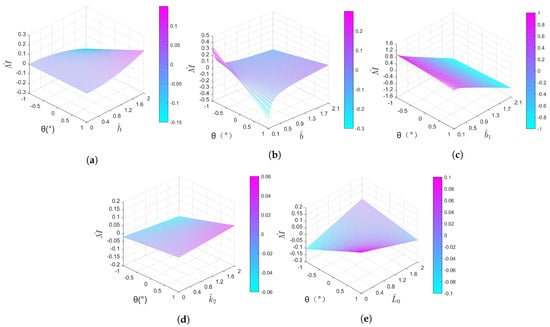
Figure 2.
Influence of mechanism structural dimensions on torque. (a) . (b) . (c) . (d) . (e) .
As shown in Figure 2a, the impact of structural dimension on dimensionless torque is depicted. It can be observed that an increase in results in a larger variation in , indicating an increase in mechanism stiffness.
In Figure 2b, represents the compression or extension of the springs. Larger compression or extension corresponds to greater negative or positive stiffness, respectively. It is evident that, with an increase in , the stiffness changes from a positive value to a negative value. The smallest absolute value of stiffness is achieved at , indicating that greater pre-compression or pre-tension of the springs in their initial positions leads to more significant negative or positive stiffness.
In Figure 2c, when the values of and are not equal, an initial torque is generated in the initial position due to the imbalance between and , causing the static equilibrium position of the mechanism to not coincide with the initial position at . Therefore, the mechanism can adjust the static equilibrium position by varying the difference between and . When , the value of corresponds to the static equilibrium position. Additionally, there is an initial torque acting at the initial position when .
As shown in Figure 2d, represents the stiffness ratio of the two springs. In the initial position at , when , an initial torque is generated due to the imbalance between the forces and produced by the two springs, causing the static equilibrium position to not coincide with the initial position. As gradually increases, the force exerted by the spring also increases, leading to an increase in the mechanism’s rotational stiffness.
The positive stiffness is defined as follows: the larger the torque of the mechanism, the larger the deformation angle. In the curve of the torque M of the mechanism and the deformation angle , it is shown as a positive slope. However, the negative stiffness is defined as follows: the torque becomes smaller when the deformation angle increases, so it shows a negative slope in the curve. In Figure 2e, when the original length of the springs , the slope is negative in the plane, so the mechanism exhibits negative stiffness, and, as increases, the negative stiffness decreases. Conversely, when , the slope is positive in the plane, so the mechanism displays positive stiffness, and, as increases, the positive stiffness becomes greater.
It is worth noting that, when designing the positive- or negative-stiffness mechanism separately, the design of structural dimension differs. In the positive-stiffness mechanism, larger results in greater positive stiffness, whereas, in the negative-stiffness mechanism, larger leads to lower stiffness. From the analysis provided above, it is evident that changes in structural dimensions and do not affect torque variations at the initial position, but they can directly alter the magnitude of rotational stiffness by changing the spring forces and . Changes in and introduce variations in initial torque and stiffness.
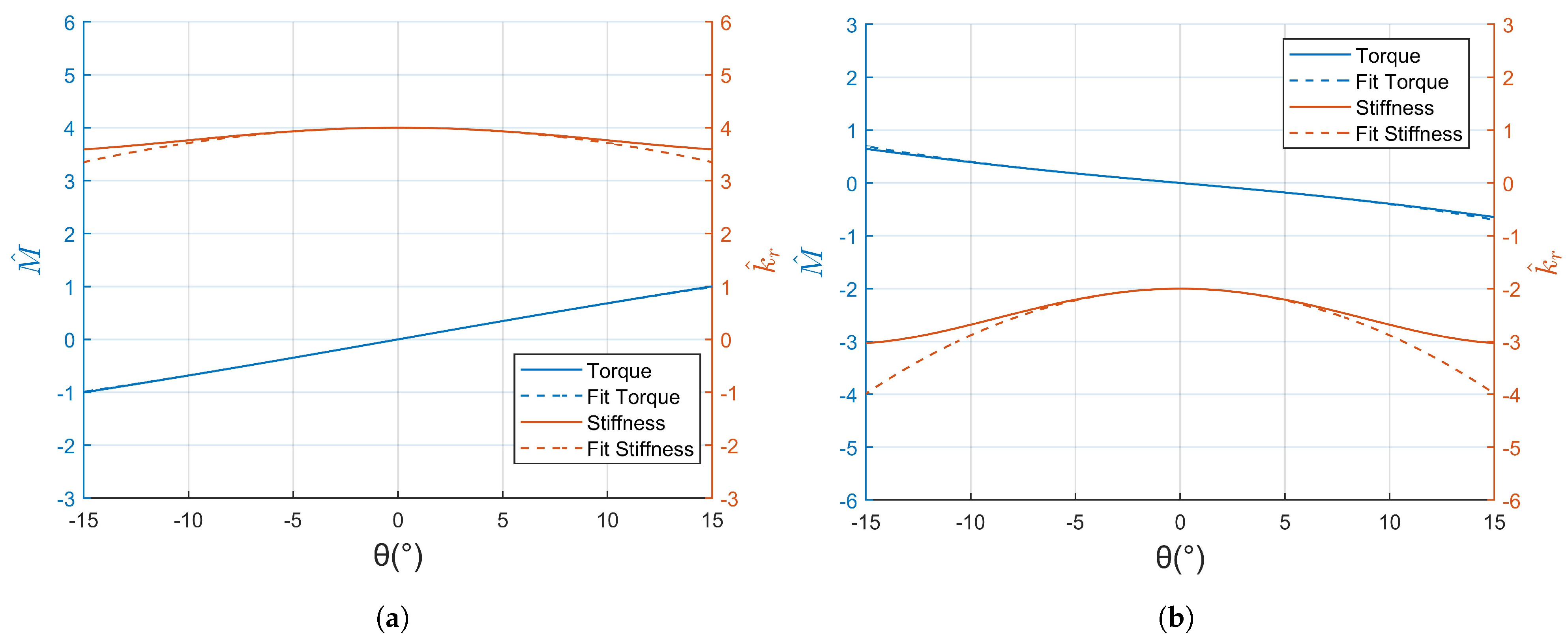
Figure 3 depicts the dimensionless torque/dimensionless stiffness-angle curves. The stiffness formula derived from Formula (5) is very complex, which is not conducive to the subsequent nonlinear analysis. Therefore, a Taylor series expansion is employed to fit the torque at the initial position , followed by taking the derivative of the fitted torque to obtain the stiffness formula. When , as shown in Figure 3a, springs and are stretched at the initial position , resulting in an initial torque of zero and maximum stiffness. In the range of ±15°, the mechanism exhibits positive stiffness. When , as shown in Figure 3b, springs and are compressed at the initial position , yielding an initial torque of zero and maximum stiffness. The stiffness variation near the initial position is relatively small, indicating weaker nonlinearity. Equation (5) is expanded into a third-order Taylor series fit at for the dimensionless torque:
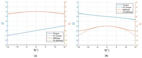
Figure 3.
Dimensionless torque/dimensionless stiffness-angle curves and Taylor expansion fitted curves. (a) . (b) .
The fitted results are shown in Figure 3a,b. They accurately fit the dimensionless torque and stiffness within the range of ±5°, which is significantly larger than the working angle range of the FSM. In Equations (8) and (9), the first-order coefficient k of represents the linear stiffness component, while the third-order coefficient characterizes the degree of stiffness nonlinearity. The greater the absolute value of , the higher the degree of nonlinearity.
The comparison of different variable-stiffness mechanisms is shown in Table 1. The minimum number of springs means better symmetry (if it is even). If a linear spring can be used, this means better practicality and lower cost because the linear spring is the standard component. The equilibrium position of the variable-stiffness mechanism is defined as the position where zero torque is generated. It can change the initial displacement of the mechanism and is an important function. The preload at the equilibrium position causes the mechanism to be in a stress state for a long time, which is an unfavorable factor. Stiffness can be positive or negative, and negative stiffness plays a crucial role in vibration isolation. Therefore, the feasibility of a variable mechanism achieving negative stiffness determines its range of applicability. Through a comparison with other variable-stiffness mechanisms, we find that, apart from the disadvantageous preloading at the equilibrium position, our mechanism is advantageous in all other aspects.

Table 1.
Comparison of different variable-stiffness mechanisms.
2.3. Nonlinear Analysis of the Mechanism
In order to analyze the impact of nonlinearity, as proposed previously in Section 2.2, we employed a Taylor series expansion to fit and simplify the torque-angle function, substituting it into the dynamic equation to solve for the frequency response curve. The harmonic balance method was used to solve the nonlinear dynamics of the variable-stiffness mechanism. The dimensionless torque of the variable-stiffness mechanism was accurately fitted near the initial position using a third-order Taylor series expansion. When the system is subjected to harmonic excitation, its dynamic equation becomes a damped Duffing system:
where J represents the rotational inertia of the mechanism, c is the rotational damping, B is the amplitude of the excitation, is the excitation frequency, and is the phase. For dimensionless processing convenience, we multiply the right-hand side of the equation by the stiffness k. Using the harmonic balance method, Equation (10) is solved, assuming the solution takes the form
where A is the response amplitude. Non-dimensionalizing Equation (10), we have
where . Substituting Equation (11) into Equation (10), we obtain the following equation:
where is the frequency ratio. Setting the coefficients of the first harmonic terms on both sides of Equation (13) equal, we obtain
From Equation (14), we can derive the relationship between the system’s dynamic amplitude and frequency:
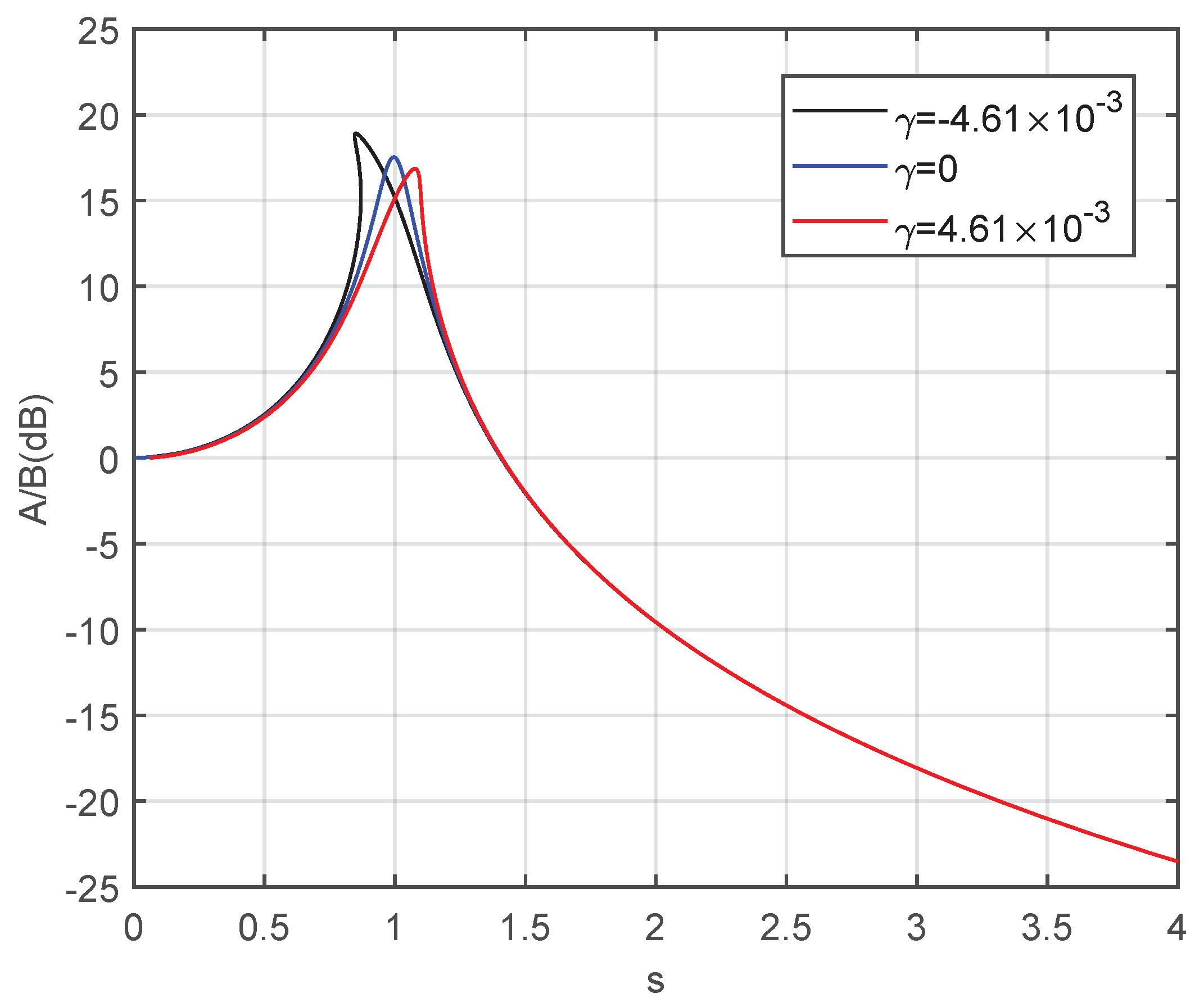
Based on Equation (16), the graph in Figure 4 illustrates the influence of nonlinearity on the amplitude–frequency response in the variable-stiffness system. When the nonlinearity represented by increases from negative to positive values at the same damping ratio, the resonance peak in the amplitude–frequency response curve shifts downward and to the right. However, in the case of a small working range near the initial position for the variable-stiffness mechanism, is extremely small. For FSM, which operates within a very narrow angle range, the nonlinearity of the stiffness can be neglected, and the variable-stiffness FSM can be analyzed as a linear system.
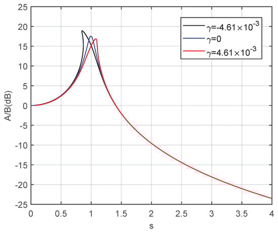
Figure 4.
Influence of nonlinearity on the amplitude-frequency response curve of the variable-stiffness system.
3. Experimental Verification
3.1. FSM with Variable Stiffness Experiment
Due to the very narrow working angle range of the FSM, static measurements of the torque–angle relationship are not suitable because friction has a significant impact on measurement accuracy. Therefore, it is challenging to accurately measure the angle and torque of the FSM directly to validate the torque of the variable-stiffness mechanism as derived in Equation (5).
To address this, dynamic measurements using a frequency sweep experiment are employed. This dynamic measurement method leverages the mechanical resonance’s “amplification” effect to obtain more accurate measurements of the mechanism’s stiffness. The approach involves conducting a frequency sweep experiment to obtain the frequency response curve of the FSM. Subsequently, the experimental results are fitted to determine the FSM’s stiffness. This method helps verify the feasibility of applying the variable-stiffness mechanism to the FSM and analyze the impact of stiffness nonlinearity.
The frequency sweep experiment involved generating 200 sinusoidal excitation forces, progressing from low frequency to high frequency in order. For each frequency, the corresponding amplitude ratio and phase difference were measured.
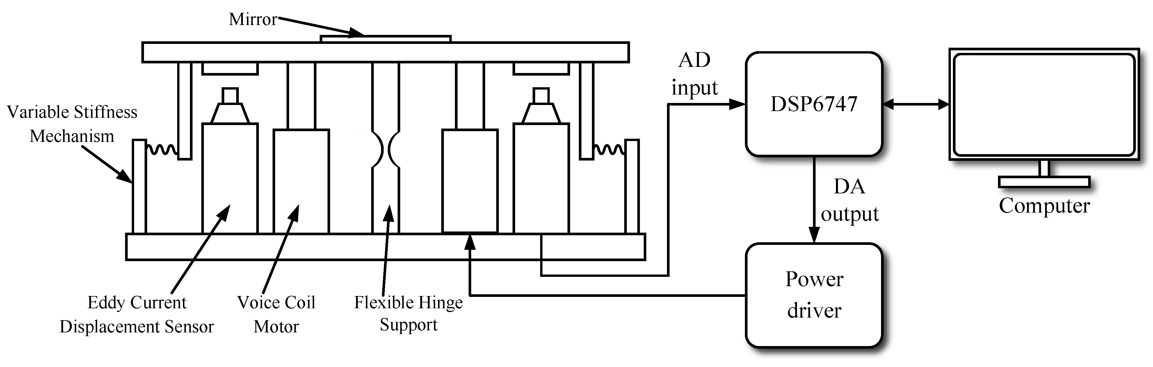
As shown in Figure 5, the experimental setup for the variable-stiffness FSM is illustrated. The frequency sweep signal is generated by the DSP6747 microcontroller and is subsequently output via DA conversion. It is then used to drive the voice-coil motors on both sides of the flexible hinge via the power driver. The displacement information is collected by the eddy current displacement sensors on both sides of the flexible hinge, and these data are transmitted to the microcontroller via the AD input. The microcontroller communicates with the computer to transfer the data for further processing.
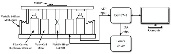
Figure 5.
Schematic of the variable-stiffness FSM experiment.
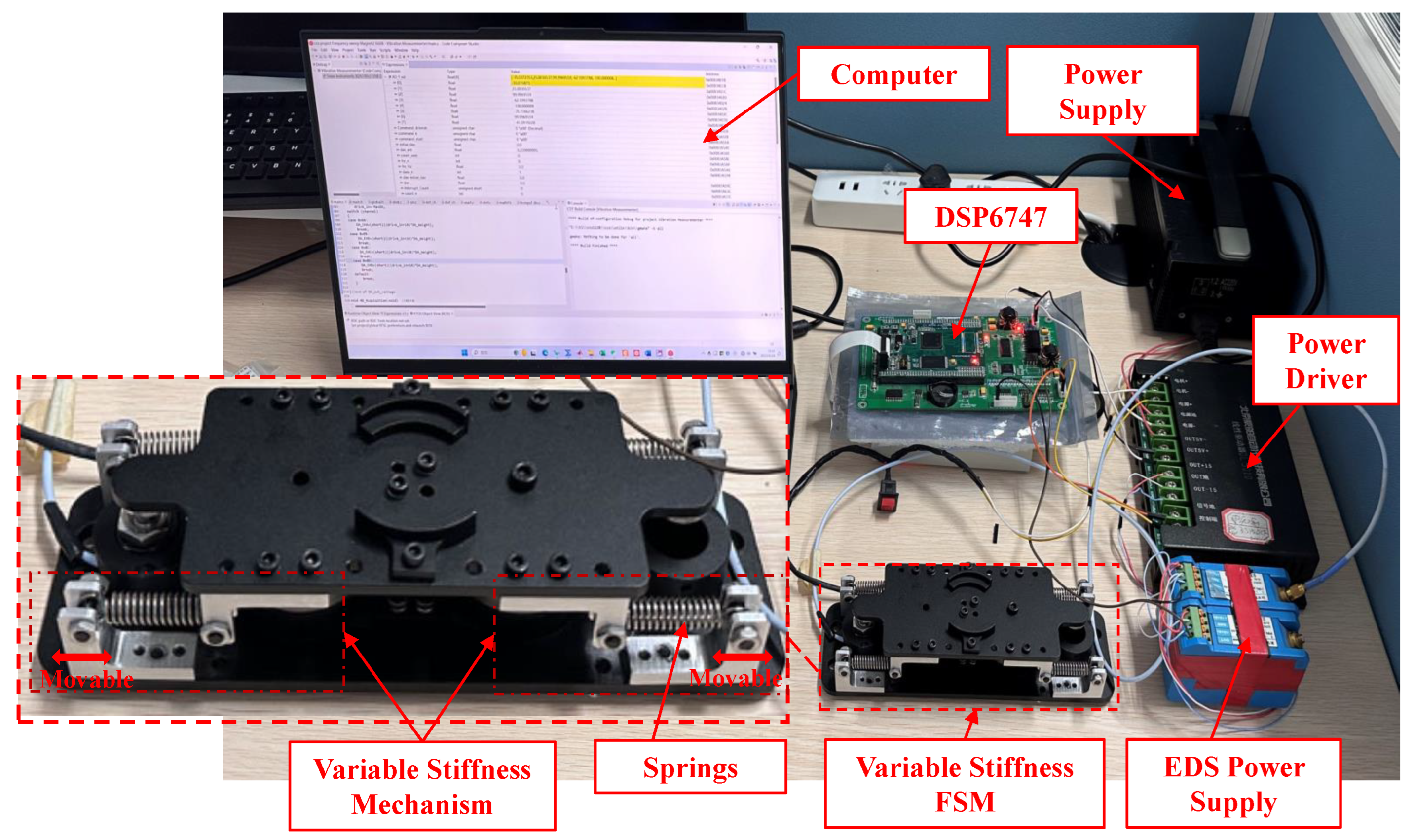
The experimental platform for the variable-stiffness FSM is depicted in Figure 6. The fabricated variable-stiffness mechanism is assembled at both ends of the FSM. The rotation center of the variable-stiffness mechanism coincides with the rotation center of the flexible hinge of the FSM. The movable hinge of the variable-stiffness mechanism is installed on the base of the FSM. We can change the total stiffness of the FSM by moving the movable hinge.
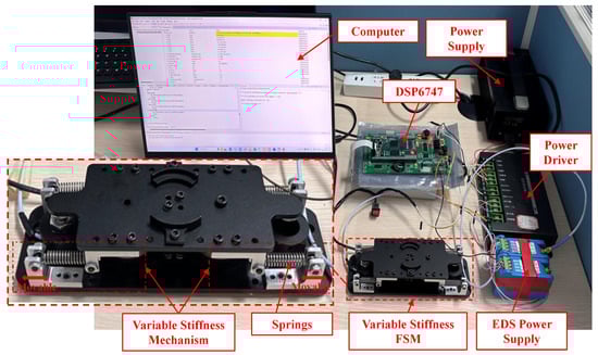
Figure 6.
Variable-stiffness FSM experimental platform.The fabricated variable-stiffness mechanism is assembled at both ends of the FSM.
The experiments were carried out using the controlled variable method. In the same experimental set, we adjusted the position of the movable hinge to different locations, effectively changing the distance and , which represent the compression of the springs at their initial positions within the variable-stiffness mechanism. The other structural parameters remained constant. For experimental convenience, we ensured that the same springs were compressed to the same distance at their initial positions, meaning , . We used three different springs under varying structural parameter b to conduct experiments and obtain the frequency response of the FSM. This allowed us to determine the stiffness of the variable-stiffness mechanism when applied to the FSM. The parameters that remained constant in each set of experiments were , , .
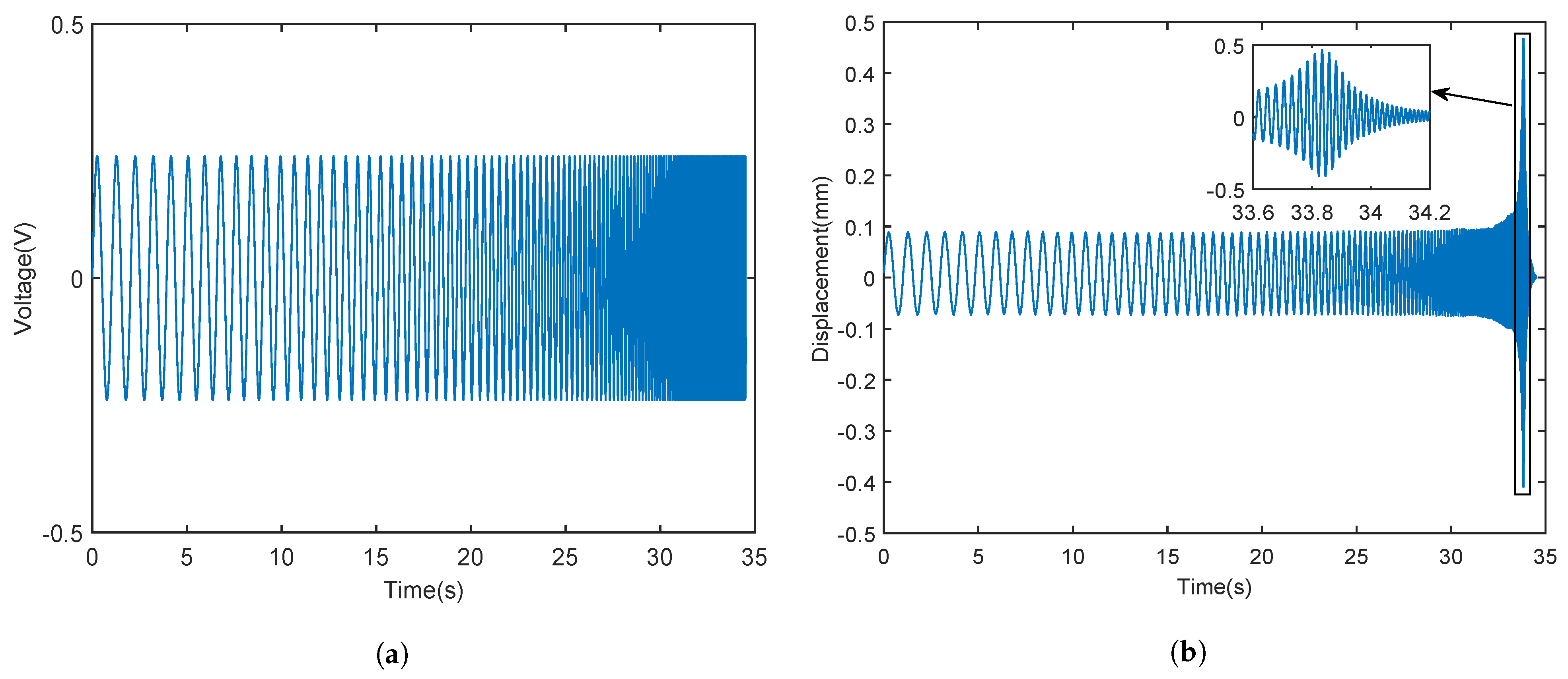
The sweep frequency time-domain signal is shown in Figure 7. The sweep frequency signal is a sinusoidal voltage signal generated by DSP6747. The frequency increases gradually from 1 Hz to 400 Hz in order. The voltage signal drives the voice-coil motor to generate an excitation force after the power drive is amplified by the power driver. The displacement generated by the excitation force is measured by the eddy current displacement sensor to obtain the displacement output signal obtained by the sweep frequency. The sweep frequency displacement output shown in Figure 7b is the corresponding ’No Springs Measure’ frequency-domain curve in Figure 8.
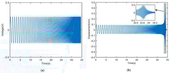
Figure 7.
The 1–400 Hz frequency sweep time-domain signal. (a) Sweep frequency voltage generated by DSP6747. (b) Sweep frequency output displacement measured by eddy current displacement sensor.
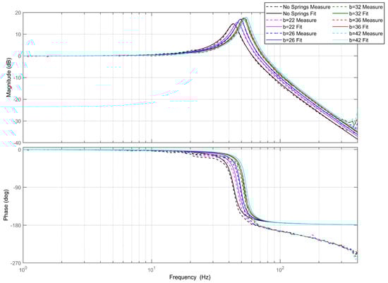
Figure 8.
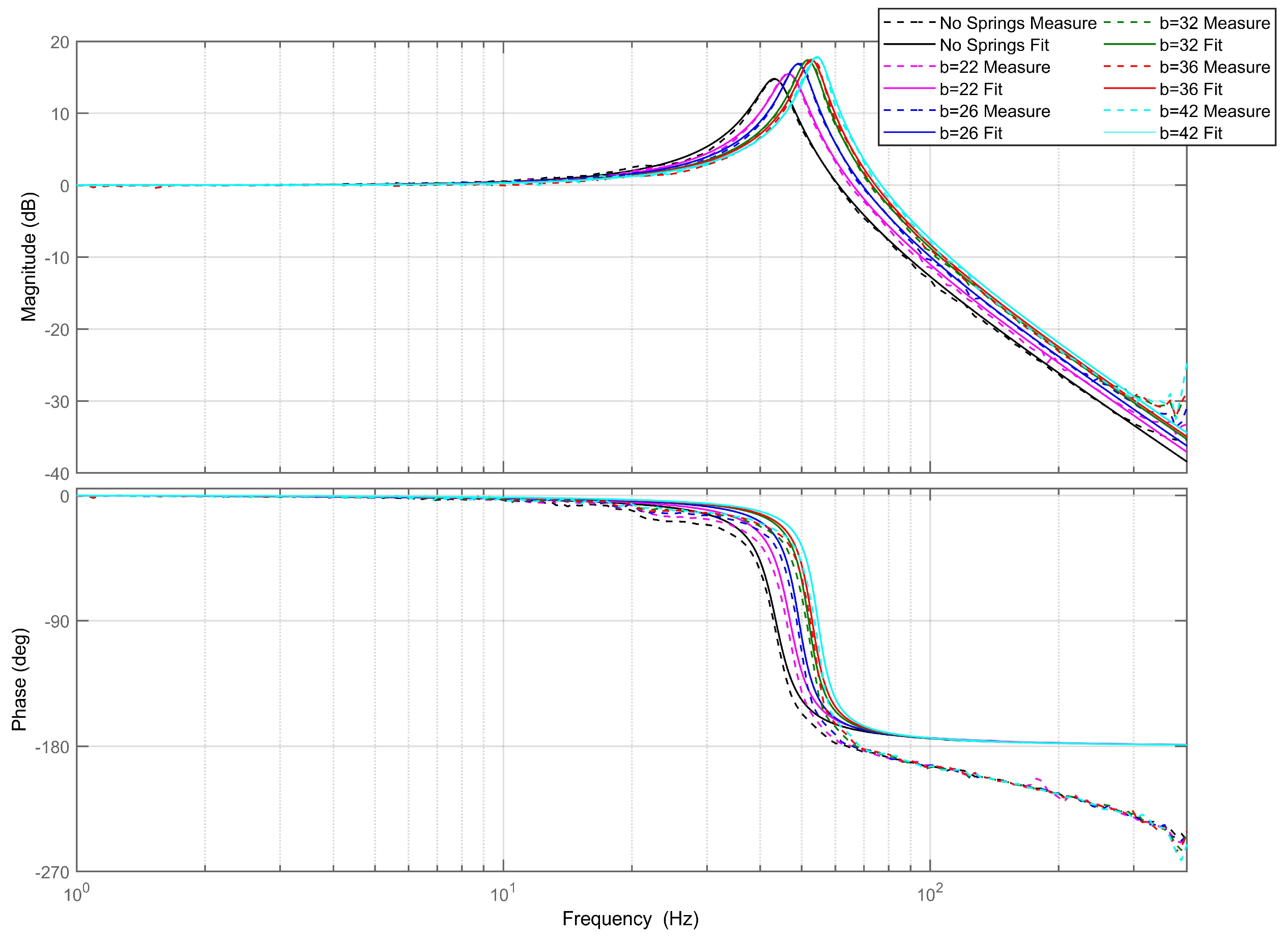
Sweep frequency experiment results and fitting of the first set of springs.
The sweep frequency experiment applies torque excitation only in the selected direction of a single rotational axis. We assume that the overall stiffness k of the FSM is a time-independent linear stiffness, neglecting nonlinear friction issues and treating the FSM as a linear system. By disregarding the small nonlinear stiffness parameter , the FSM can be simplified into the mechanical model represented by Equation (18), where is the sinusoidal excitation force, is the amplitude of the excitation force, is the excitation frequency, and is the phase difference. Taking the Laplace transform of Equation (18) yields the transfer function of the FSM, as shown in Equation (19).
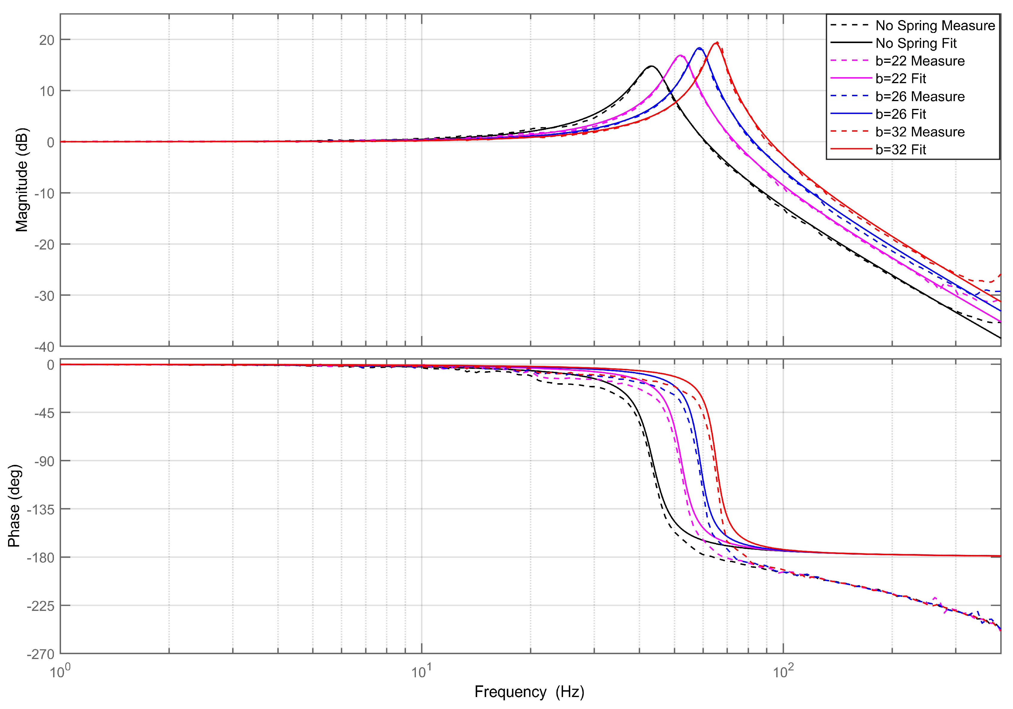
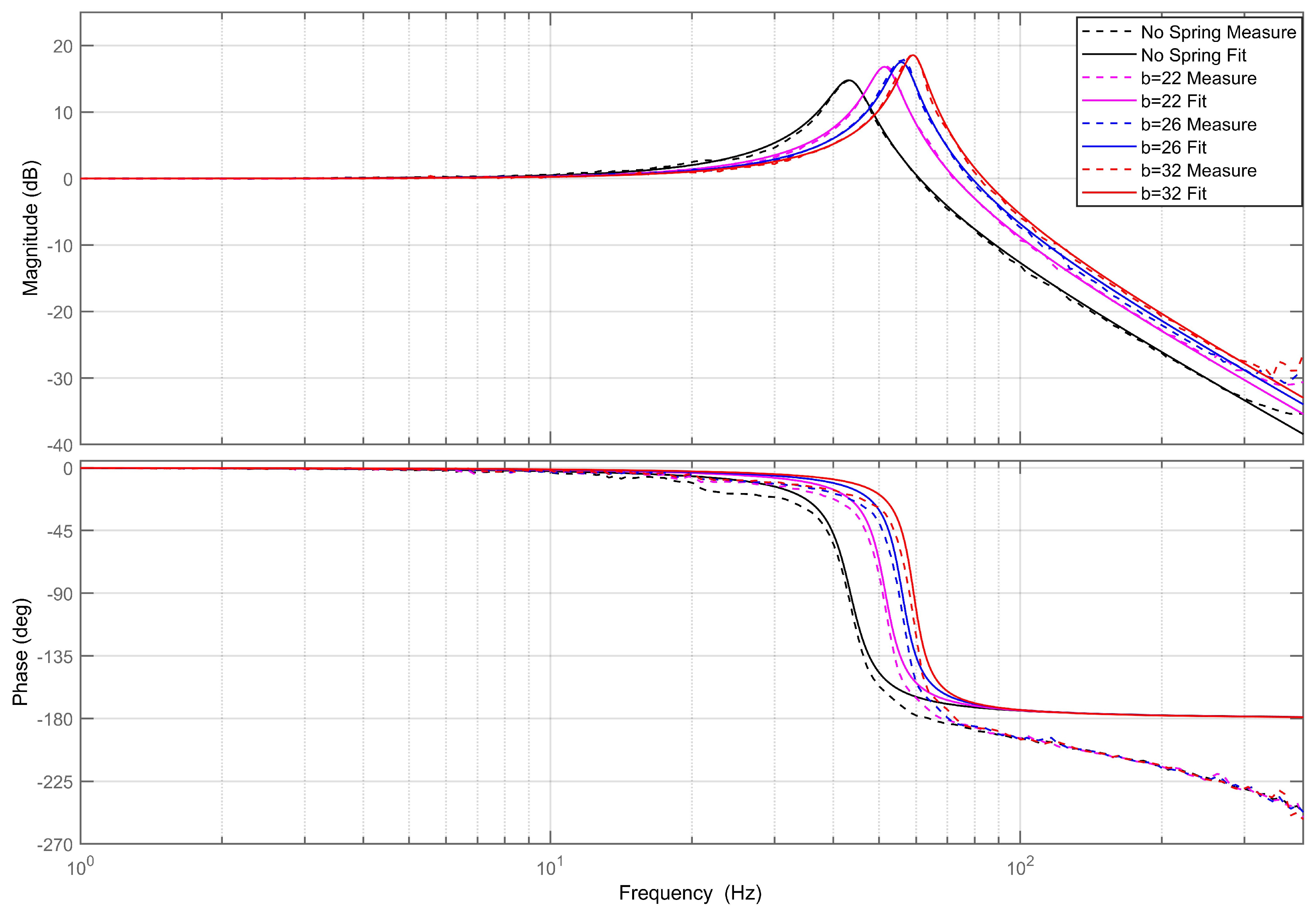
The results from the sweep frequency experiment are fitted to obtain the system’s natural frequency and damping ratio . This allows us to determine the system’s rotational stiffness k. The rotational stiffness of the FSM is composed of the stiffness of the flexible hinge and the stiffness added by the variable-stiffness mechanism. First, it is necessary to perform the sweep frequency experiment on the FSM without the variable-stiffness mechanism to obtain the stiffness of the flexible hinge. Then, we can test the FSM with the variable-stiffness mechanism added to determine the total stiffness. The stiffness of the variable-stiffness mechanism is obtained by subtracting the flexible hinge stiffness from the total stiffness. In the experiment, the sweep frequency range is 1–400 Hz, and Equation (19) is used to fit the sweep frequency results. Figure 8, Figure 9 and Figure 10 show the sweep frequency results for three sets of spring variable-stiffness mechanism-equipped FSMs, with different original spring lengths of , , and , and spring stiffnesses of , , and , under different structural parameters b.
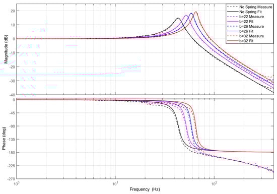
Figure 9.
Sweep frequency experimental results and fitting of the second set of springs.
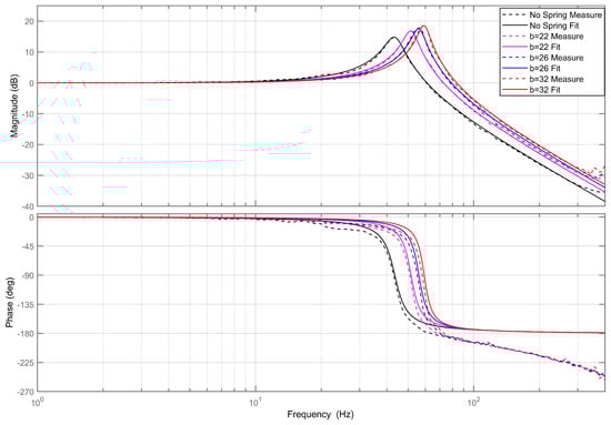
Figure 10.
Sweep frequency experimental results and fitting of the third set of springs.
In order to guarantee the durability of the spring stiffness for long-term use, the chosen spring material is SUS304-WPB, known for its corrosion resistance, tolerance to high and low temperatures, and good fatigue resistance. During spring operation, we also considered working within of its maximum elongation to extend the spring’s lifespan.
We analyzed the sweep frequency results of Figure 8, Figure 9 and Figure 10 to obtain Table 2, Table 3 and Table 4. The experimental values for k are the measured stiffnesses of the variable-stiffness mechanism, and the theoretical values for k are obtained from Equation (5). The errors for the three sets of springs are ,, , respectively. All three sets of experimental values are greater than the theoretical values, which may be due to the friction at the hinges on both ends of the springs, increasing the stiffness obtained in the experiments. Taking the average experimental stiffness within the same group yields the average experimental stiffness. The larger the average experimental stiffness, the greater the pre-compression or tension force required for the springs. Therefore, the frictional force at the hinges on both ends of the springs is greater. From the three sets of experimental values, it can be observed that the larger the average experimental stiffness, the larger the average error. Thus, considering the influence of friction makes the experimental error smaller.
Table 2.
Experimental results and analysis for the first set of springs.
Table 3.
Experimental results and analysis for the second set of springs.
Table 4.
Experimental results and analysis for the third set of springs.
From the experimental results, it is evident that the magnitude–frequency characteristics exhibit reduced accuracy in the range of 300 Hz to 400 Hz. This inaccuracy is primarily attributed to the attenuation of displacement magnitude and the subsequent decrease in signal-to-noise ratio in this frequency range. As for the phase–frequency characteristics of the three experimental sets, fitting becomes less accurate at higher frequencies. This phenomenon can be attributed to the inherent delay in the eddy current displacement sensor during measurement. As the frequency increases during measurement, the displacement changes more rapidly, resulting in a more significant impact from this delay. This delay becomes apparent in phase differences. Therefore, accounting for the sensor delay issue will result in phase–frequency curves that closely align with the fitted curves.
The sweep frequency experiment results for all three sets of springs can be accurately fitted using the linear system transfer function in Equation (19). There is no issue of resonance peak shift caused by nonlinearity, as depicted in Figure 4. Therefore, it is reasonable to approximate the variable-stiffness FSM system as a linear system.
We can note that, in the sweep frequency-domain analysis diagram from Figure 8 to Figure 10, only a single resonance peak appears in the frequency range of 1–400 Hz, and higher-order resonance peaks appear above 400 Hz frequency. For the research work of this paper, we only need to study the stiffness change in the variable-stiffness mechanism in the FSM working direction, that is, only the first resonance peak is discussed.
3.2. FSM Variable Load Experiment
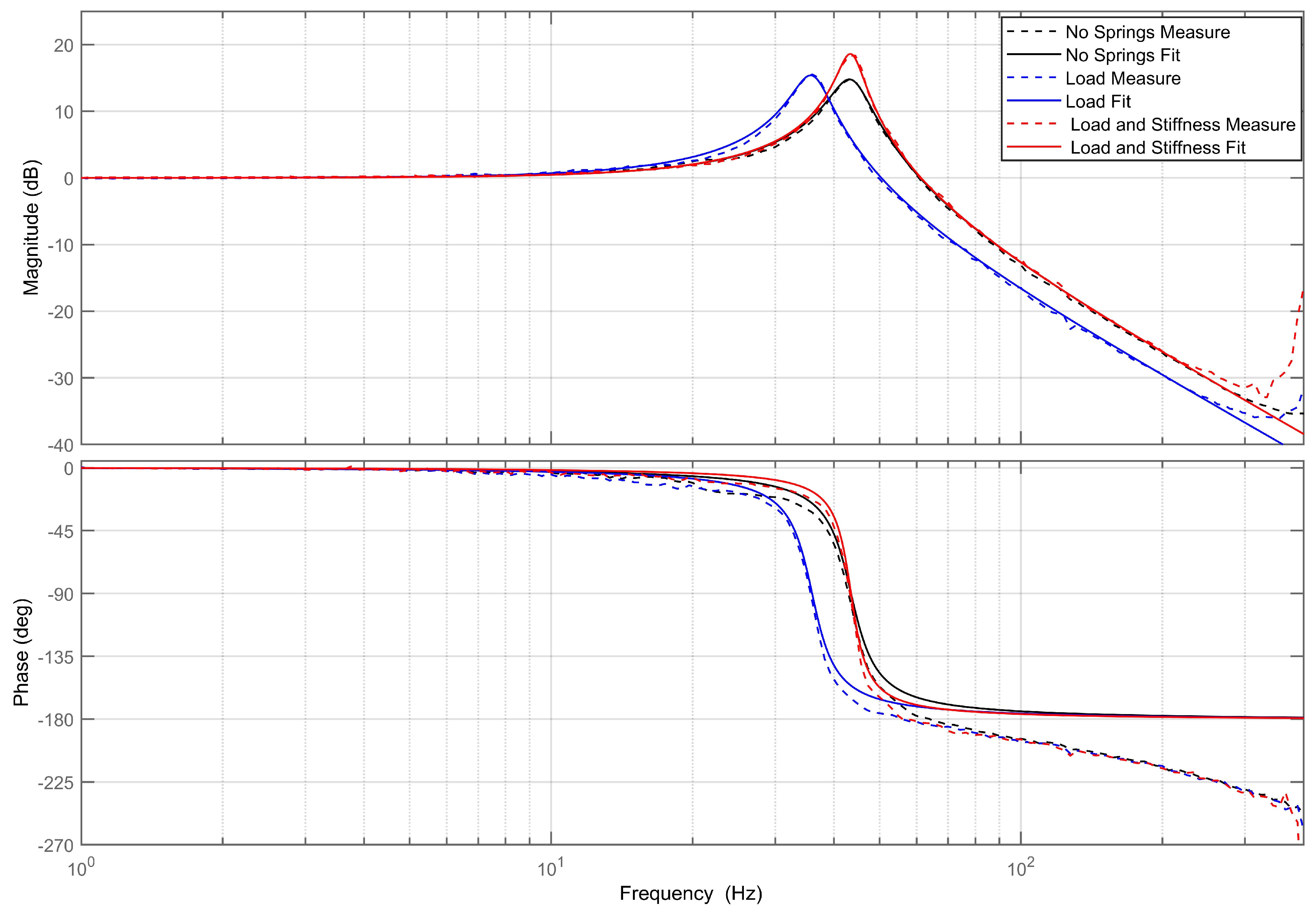
In traditional FSMs that employ flexible hinges as rotational components, altering the load on the mirror leads to changes in the transfer function of the FSM. Consequently, the control system also needs adjustments. In such cases, either the flexible hinges of the FSM or the control system itself requires redesign. However, when a FSM utilizes the variable-stiffness mechanism, making adjustments to the structural parameter b to modify the initial spring length is sufficient for controlling the mirror’s stiffness while keeping the resonance frequency consistent. When combined with other damping adjustment methods, a variable-stiffness mechanism can ensure that the FSM’s transfer function remains consistent even after altering the load, and there would be no need to redesign the control system.
As shown in Figure 11, the sweep frequency results and fitting before and after changing the load are illustrated. Without the addition of the variable-stiffness mechanism, the FSM has a moment of inertia , stiffness of , a resonant frequency of , and a peak value of . After adding the load, the moment of inertia of the FSM increased to , the resonant frequency changed to , and the peak value increased to . Both the resonant frequency and peak value experienced alterations.
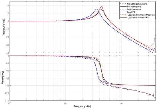
Figure 11.
Sweep frequency experiment results and fitting before and after changing the load.
When the variable-stiffness mechanism is added, the structural parameters of the variable-stiffness mechanism are as follows: , , , . The resonant frequency becomes , and the peak value rises to . The FSM’s rotational stiffness is , while the rotational stiffness of the variable-stiffness mechanism is .
The experimental results indicate that altering the stiffness can adjust the resonant frequency. The resonant frequency differs by only 0.2% before and after changing the load, demonstrating that the resonant frequency remains essentially consistent.
4. Conclusions
This article introduces a variable-stiffness mechanism for rotation and applies it to a FSM. The variable-stiffness mechanism can change the rotational stiffness, but the change in stiffness has nonlinear characteristics. The smaller the rotation angle range of the mechanism stiffness, the weaker the nonlinearity. FSMs typically operate within a limited angle range, which allows for the application of the variable-stiffness mechanism to avoid nonlinear problems, approximating the variable-stiffness FSM system as a linear system.
Sweep frequency experiments were conducted with three sets of different springs under varying structural parameter b values. The experimental results for the stiffness of the variable-stiffness mechanisms of the three spring sets had errors of , , and compared to the theoretical values. These errors would be even smaller when considering friction, confirming the feasibility of using the variable-stiffness mechanism in the FSM and the accuracy of stiffness adjustments. The variable-stiffness mechanism can maintain a consistent resonant frequency of the FSM when subjected to load changes, and, when combined with variable dampers, it ensures that the frequency characteristics of the system remain consistent before and after adding the load, eliminating the need for a control system redesign due to load variations.
Author Contributions
Theoretical analysis: J.L. and Y.M.; Designing experiments and analyzing data: W.D. and J.L.; Conducting simulations: F.Y. and L.Z.; Writing the paper: J.L. and L.Z.; Revising the paper: W.D. and L.M. All authors have read and agreed to the published version of the manuscript.
Funding
This work was supported by the National Natural Science Foundation of China (Grant No. 62271109).
Institutional Review Board Statement
Not applicable.
Informed Consent Statement
Not applicable.
Data Availability Statement
Data is contained within the article.
Conflicts of Interest
The authors declare no conflict of interest.
References
- Schlarp, J.; Csencsics, E.; Schitter, G. Optical scanning of a laser triangulation sensor for 3-D imaging. IEEE Trans. Instrum. Meas. 2019, 69, 3606–3613. [Google Scholar] [CrossRef]
- Dong, Z.; Jiang, A.; Dai, Y.; Xue, J. Space-qualified fast steering mirror for an image stabilization system of space astronomical telescopes. Appl. Opt. 2018, 57, 9307–9315. [Google Scholar] [CrossRef] [PubMed]
- Sinn, A.; Riel, T.; Deisl, F.; Schachner, S.; Schitter, G. High-bandwidth tip-tilt vibration compensation in telescope systems. IFAC-PapersOnLine 2019, 52, 549–554. [Google Scholar] [CrossRef]
- Deng, J.; Xue, W.; Liang, W.; Zhou, X.; Mao, Y. On adjustable and lossless suppression to disturbances and uncertainties for nonminimum-phase laser pointing system. ISA Trans. 2023, 136, 727–741. [Google Scholar] [CrossRef] [PubMed]
- Zhong, J.; Nishida, R.; Shinshi, T. Design and precision tracking control of a high-bandwidth fast steering mirror for laser beam machining. Precis. Eng. 2022, 73, 128–139. [Google Scholar] [CrossRef]
- Cao, K.; Hao, G.; Liu, Q.; Tan, L.; Ma, J. Hysteresis modeling and compensation of fast steering mirrors with hysteresis operator based back propagation neural networks. Micromachines 2021, 12, 732. [Google Scholar] [CrossRef]
- Hao, G.; Li, H.; Chang, Y.-H.; Liu, C.-S. Design of Four-DoF Compliant Parallel Manipulators Considering Maximum Kinematic Decoupling for Fast Steering Mirrors. Actuators 2021, 10, 292. [Google Scholar] [CrossRef]
- Liu, C.-S.; Wu, Y.-C.; Lan, Y.-J. Design of 4-DOF Voice Coil Motor with Function of Reducing Laser Geometrical Fluctuations. Actuators 2021, 10, 320. [Google Scholar] [CrossRef]
- Zhao, T.; Tong, W.; Mao, Y. Hybrid Nonsingleton Fuzzy Strong Tracking Kalman Filtering for High Precision Photoelectric Tracking System. IEEE Trans. Ind. Inform. 2022, 19, 2395–2408. [Google Scholar] [CrossRef]
- Fu, J.; Yan, C.; Liu, W.; Yuan, T. Stiffness optimization of two-axis flexible supporting platform for fast steering mirror. Opt. Precis. Eng. 2015, 23, 3378–3386. (In Chinese) [Google Scholar]
- Zhang, W.; Yuan, J.; Yan, C.; Gao, Z.; Dong, Y. Multi-objective optimization design of natural frequency of two-degree-of-freedom fast steering mirror system. IEEE Access 2021, 9, 33689–33703. [Google Scholar] [CrossRef]
- Han, W.; Shao, S.; Zhang, S.; Tian, Z.; Xu, M. Design and modeling of decoupled miniature fast steering mirror with ultrahigh precision. Mech. Syst. Signal Process. 2022, 167, 108521. [Google Scholar] [CrossRef]
- Lu, Y.; Yang, Y.; Xue, Y.; Jiang, J.; Zhang, Q.; Yue, H. A Variable Stiffness Actuator Based on Leaf Springs: Design, Model and Analysis. Actuators 2022, 11, 282. [Google Scholar] [CrossRef]
- Jin, H.; Luo, M.; Lu, S.; He, Q.; Lin, Y. Design and Analysis of a Novel Variable Stiffness Joint for Robot. Actuators 2023, 12, 10. [Google Scholar] [CrossRef]
- Van, R.; Sugar, T.; Vanderborght, B.; Hollander, K.; Lefeber, D. Compliant actuator designs: Review of actuators with passive adjustable compliance/controllable stiffness for robotic applications. IEEE Robot. & Autom. Mag. 2009, 16, 81–94. [Google Scholar] [CrossRef]
- Hollander, K.W.; Ilg, R.; Sugar, T.G.; Herring, D. An Efficient Robotic Tendon for Gait Assistance. ASME J. Biomech. Eng. 2006, 128, 788–791. [Google Scholar] [CrossRef]
- Migliore, S.A.; Brown, E.A.; DeWeerth, S.P. Biologically inspired joint stiffness control. In Proceedings of the 2005 IEEE International Conference on Robotics and Automation, Barcelona, Spain, 18–22 April 2005; IEEE: Piscataway, NJ, USA, 2005; pp. 4508–4513. [Google Scholar] [CrossRef]
- Li, X.; Chen, W.; Lin, W. Design of a structure-controlled variable stiffness actuator based on rotary flexure hinges. In Proceedings of the 2017 IEEE International Conference on Robotics and Automation (ICRA), Singapore, 29 May–3 June 2017; IEEE: Piscataway, NJ, USA, 2017; p. 7988689. [Google Scholar] [CrossRef]
- Karnopp, D. Active and SemiActive Vibration Isolation. J. Mech. Des. 1995, 117, 409–423. [Google Scholar] [CrossRef]
- Hu, X.; Zhou, C. Dynamic analysis and experiment of Quasi-zero-stiffness system with nonlinear hysteretic dampin. Nonlinear Dyn. 2022, 103, 2153–2175. [Google Scholar] [CrossRef]
- Le, T.D.; Ahn, K.K. A vibration isolation system in low frequency excitation region using negative stiffness structure for vehicle seat. J. Sound Vib. 2011, 330, 6311–6355. [Google Scholar] [CrossRef]
- Lee, C.M.; Bogatchenkov, A.H.; Goverdovskiy, V.N.; Shynkarenko, Y.V.; Temnikov, A.I. Position control of seat suspension with minimum stiffnes. J. Sound Vib. 2006, 292, 435–442. [Google Scholar] [CrossRef]
- Hu, X.; Zhou, C. The effect of various damping on the isolation performance of quasi-zero-stiffness system. Mech. Syst. Signal Process. 2022, 171, 108944. [Google Scholar] [CrossRef]
- Zhang, H.; Li, X.; Zhang, L. Bifurcation analysis of a micro-machined gyroscope with nonlinear stiffness and electrostatic forces. Micromachines 2021, 12, 107. [Google Scholar] [CrossRef] [PubMed]
- Xu, Y.; Guo, K.; Li, J.; Li, Y. A novel rotational actuator with variable stiffness using S-shaped springs. IEEE/ASME Trans. Mechatronics 2020, 26, 2249–2260. [Google Scholar] [CrossRef]
- Govindan, N.; Ramesh, S.; Thondiyath, A. Design of a variable stiffness joint module to quickly change the stiffness and to reduce the power consumption. IEEE Access 2020, 8, 138318–138330. [Google Scholar] [CrossRef]

Disclaimer/Publisher’s Note: The statements, opinions and data contained in all publications are solely those of the individual author(s) and contributor(s) and not of MDPI and/or the editor(s). MDPI and/or the editor(s) disclaim responsibility for any injury to people or property resulting from any ideas, methods, instructions or products referred to in the content. |
© 2023 by the authors. Licensee MDPI, Basel, Switzerland. This article is an open access article distributed under the terms and conditions of the Creative Commons Attribution (CC BY) license (https://creativecommons.org/licenses/by/4.0/).