Abstract
In order to better meet the practical application needs of mobile robots, this study innovatively designs an autonomous obstacle avoidance and trajectory planning control strategy with low computational complexity, high cost-effectiveness, and the ability to quickly plan a collision-free smooth trajectory curve. This article constructs the kinematic model of the mobile robot, designs a dual-loop trajectory tracking control strategy for position control law and attitude control law algorithms, and improves the traditional artificial potential field method to achieve a good obstacle avoidance strategy for mobile robots. Based on the dual-loop trajectory tracking control and the improved artificial potential field method, the autonomous obstacle avoidance and trajectory planning scheme of the mobile robot is designed, and closed-loop stability verification and analysis are conducted on the overall control system. And through the detailed simulation and experiments, the advantages of the proposed method in trajectory tracking accuracy and motion stability compared to the existing methods are verified, showing good effectiveness and feasibility and laying a good foundation for the application of mobile robots in practical complex scenes.
1. Introduction
The working environment of mobile robots is more complex and diverse than that of fixed robots [1,2,3], and the requirement of intelligent autonomy for mobile robots is higher. The excellence of a trajectory planning algorithms is one of the important indicators for the intelligent autonomy of mobile robots [4,5,6,7,8,9,10]. A good trajectory planning algorithm can effectively improve the autonomous obstacle avoidance ability of mobile robots, which has a profound impact on their motion efficiency, trajectory tracking accuracy, motion stability, and service life [11].
Existing trajectory planning algorithms often perform well in specific map environments, but there are certain limitations in certain environments. For example, the A-star algorithm is a commonly used and classic trajectory search algorithm [12,13,14,15] which can meet specific needs through customized methods based on the different types of networks and data structures. The A-star algorithm has high flexibility and supports dynamic environments. The A-star algorithm can perform trajectory planning in dynamic environments; when obstacles in the environment change, the A-star algorithm can quickly adapt to new obstacles and plan the shortest trajectory. However, the A-star algorithm has drawbacks such as slow computation speed and large computational load in situations where the grid map size is too large and the distribution of obstacles is complex. Based on the A-star algorithm, Li et al. [13] proposed a three-dimensional-space unmanned aerial vehicle trajectory planning model that could solve the problems of high computational complexity and long computational time to some extent; however, their algorithm cannot be applied to complex dynamic scenes, and further research is needed on trajectory selection in obstacle avoidance. Liu et al. [12] optimized the traditional A-star algorithm and designed new trajectory finding rules and algorithm structures, which can effectively improve the trajectory planning ability of mobile robots in complex scenarios; however, its running speed still needs to be improved.
The Dijkstra algorithm has high flexibility and can be modified according to specific needs in practical applications to achieve the expected results [16,17,18,19]. However, this algorithm has high memory consumption, and due to the need to maintain two sets, it requires a lot of additional memory space. In addition, this algorithm is only applicable to the single-source shortest path, which can only calculate the shortest path from one starting point to each node, and cannot handle the problem of multiple-source shortest paths.
The dynamic programming method is a commonly used method for solving optimal problems, which decomposes originally complex problems into multiple subproblems that are relatively easy to solve. By solving subproblems and gradually recursively obtaining the global optimal solution, complex problems such as graphic search and network flow can be effectively solved, avoiding repetitive calculations, saving time and memory space, and reducing time complexity when solving certain problems [20,21,22,23]. However, due to the need to save and update the optimal solution of the subproblem, this algorithm requires additional space for storage, which can occupy a considerable amount of storage space when the problem is relatively complex. On the other hand, the increase in states when solving complex problems makes it very difficult to determine the state transition equation. In addition, the conditions under which this algorithm is used are quite stringent, and it needs to meet the optimal substructure and non-aftereffect property.
The trajectory planning algorithm using deep learning is limited by the training sample set, and if the number of samples is too small or not comprehensive, it cannot guarantee the optimality of the trajectory when facing new map environments [24,25,26,27,28]. Additionally, for biomimetic intelligent algorithms such as the ant colony algorithm [29,30] and the genetic algorithm [31,32], due to their complex algorithm principles, they are prone to defects such as improper selection of trajectory finding parameters, and are prone to the problems such as high iteration times and an inability to converge, causing an unsatisfactory trajectory finding effect.
The artificial potential field method is a widely used algorithm in path planning, which can be applied to various scenarios, especially in obstacle avoidance and navigation problems involving robots and unmanned vehicles. The following are some specific application scenarios: Robot path planning: The artificial potential field method was originally designed for robot path planning. In robot navigation, the target point generates attraction forces, while obstacles generate repulsive forces, and the robot plans its path based on the synthesis of these forces to safely and efficiently reach the target position. Autonomous vehicles: Similar to robots, autonomous vehicles can also use the artificial potential field method for path planning and obstacle avoidance. The vehicles perceive obstacles in the surrounding environment through sensors and plan their driving path based on the combination of attraction forces and repulsive forces. Air traffic control: In air traffic control, the artificial potential field method can be used for aircraft trajectory planning and conflict avoidance. Each aircraft is viewed as a dynamic obstacle, while other aircraft and destinations generate corresponding attraction forces and repulsive forces, thereby helping the aircraft plan its trajectory safely and efficiently. Group behavior simulation: The artificial potential field method can also be used to simulate group behavior, such as schools of bird and fish. In this case, each individual is influenced by other individuals and environmental factors, and the dynamic behavior of the group is simulated through the combination of attraction forces and repulsive forces. It should be noted that although the artificial potential field method can achieve good results in many situations, it also has some limitations, such as being prone to getting stuck in local optimal solutions and being sensitive to the shape of obstacles. Therefore, in practical applications, algorithm selection and adjustment need to be based on specific scenarios and requirements.
The principle of the artificial potential field algorithm is simple, easy to program and implement, and the trajectory planning speed is fast, which can be adjusted reasonably according to the actual constraints on velocity and acceleration [33,34,35]. However, the artificial potential field method is prone to local optimal solutions and unreachable problems, leading to the mobile robot falling into a deadlock and being unable to reach the target point. It is difficult to handle the boundaries of infeasible areas, which may cause the mobile robot to oscillate back and forth between obstacles and target points, making it impossible to complete trajectory planning. Tian et al. [35] applied the artificial potential field method to Continuous Hyper-Redundant Manipulators and achieved good results in trajectory planning and obstacle avoidance, but the current method is still limited, and the success rate depends on changes to the initial configuration. Based on the artificial potential field method, He et al. [34] studied a motion planning method for ships. The simulation shown that feasible motion obstacle avoidance paths can be generated in complex environments; however, the non-linear optimization of this method consumed too much time.
In conclusion, the defects of the above existing algorithms make them appear inadequate for practical application in mobile robots [36]. To better meet the practical application needs of mobile robots, this study innovatively designs an autonomous obstacle avoidance and trajectory planning control strategy with low computational complexity, high cost-effectiveness, and the ability to quickly plan a collision-free smooth trajectory curve. This article constructs the kinematic model of the mobile robot, designs a dual-loop trajectory tracking control strategy for position control law and attitude control law algorithms, and improves the traditional artificial potential field method to achieve a good obstacle avoidance strategy for a mobile robot. Based on the dual-loop trajectory tracking control and the improved artificial potential field method, the autonomous obstacle avoidance and trajectory planning scheme of the mobile robot is designed, and the closed-loop stability verification and analysis are conducted on the overall control system. And through detailed simulation and experiments, the advantages of the proposed method in trajectory tracking accuracy and motion stability compared to the existing methods are verified, showing that it has good effectiveness and feasibility and laying a good foundation for the application of mobile robots in practical complex scenes.
The remainder of this paper is organized in the following way: Section 2 describes the kinematic model of the mobile robot. The details of the control system are designed in Section 3. The system’s closed-loop stability is verified in Section 4. Section 5 analyzes the results of the simulation, experiment, and real-world application. Finally, the conclusion and future work are given by Section 6.
2. Kinematic Model of Mobile Robot
The motion state of the mobile robot is represented by the position of the geometric center point M in the coordinate system and the heading angle θ, and , , where x and y are the actual positions of the mobile robot, θ is the actual angle between the forward direction of the mobile robot and the X-axis, and v and ω are, respectively, the linear velocity and angular velocity of mobile robot; they are the control inputs in the kinematic model. The motion of the mobile robot is shown in Figure 1.
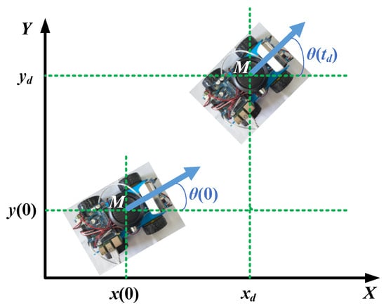
Figure 1.
The motion of mobile robot.
Here, td is the time at which the mobile robot reaches the location point (xd, yd).
The kinematic equation of the mobile robot can be defined as follows:
where .
3. Design of Control System
3.1. Design of Position Control Law
The error tracking equation is defined as follows:
where and . The subscripts “e” and “d” are defined as “error” and “desired”.
Making , , , if , assuming the desired angle , satisfies the desired trajectory tracking. And .
The position control law is defined as follows:
where .
and are bounded, and and . Because of , therefore, v is bounded, and . That is
We can obtain the following equations:
and and .
The actual position control law can be defined as follows:
3.2. Design of Attitude Control Law
The following task is to achieve angle θ tracking, θd, by designing an attitude control law, ω.
Making , the sliding mode function , and .
The attitude control law is defined as follows:
where and .
Therefore, , making , and , that is , thus achieving exponential convergence of angle θ to θd.
3.3. Autonomous Obstacle Avoidance Trajectory Planning
When the trajectory is not given and there are multiple obstacles, carrying out autonomous trajectory planning based on the control system designed above is the problem that needs to be solved in this section.
For the traditional artificial potential field method [37], a single obstacle only generates repulsive force in one direction towards the mobile robot. And the repulsive force generated by the obstacle on mobile robots increases as the distance between the obstacle and mobile robot decreases, ensuring that the mobile robot does not directly collide with obstacle when the mobile robot approaches the obstacle. On the other hand, the target point generates attraction force on the mobile robot, and only generates attraction force in one direction, and the direction of the attraction force is directed by the mobile robot towards the target point. And the attraction force generated by the target point on the mobile robot will weaken as the distance between the target point and the mobile robot decreases, resulting in zero attraction force on the mobile robot when it reaches the target point. The mobile robot moves under the combined action of attraction force and repulsion force, and the force acting on the mobile robot is shown in Figure 2.
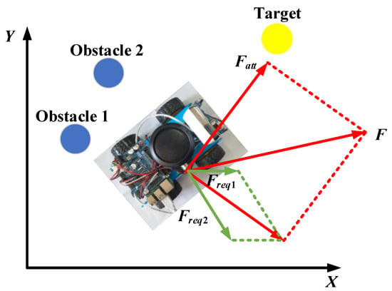
Figure 2.
The force acting on the mobile robot, where is the attraction force, and are the components of the repulsion force , and F is the summation of forces acting on the mobile robot.
The attraction force potential field function is
where is a positive proportional gain coefficient, and is a vector, which represents the Euclidean distance between the mobile robot and the target point. The vector direction is from the mobile robot to the target point. .
Correspondingly, the attraction force is the negative gradient of the attraction force field, which can be obtained as follows:
The repulsive potential field function is
where is a positive proportional gain coefficient, and is a vector, which represents the Euclidean distance between the mobile robot and the obstacle. The vector direction is from the obstacle to the mobile robot. represents the maximum distance at which the obstacle can affect the mobile robot.
Correspondingly, the repulsion force is the negative gradient of the attraction force field, which can be obtained as follows:
Based on Equations (1) and (2), it can be inferred that the following abnormal situations will occur during the movement of the mobile robot: The first scenario is the local optimal problem, where the repulsive force of the obstacle on the mobile robot is equal to the attraction force of the target on the mobile robot, but in the opposite direction, causing the mobile robot to oscillate back and forth at a certain position and be unable to reach the target point. The second scenario is the problem of a non-reachable goal with an obstacle nearby, the problem of a non-reachable goal with an obstacle nearby is due to the strong repulsive force of obstacles near the target, which causes the mobile robot to be unable to approach the target object. The schematic diagrams are shown in Figure 3 and Figure 4.
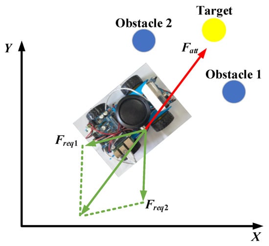
Figure 3.
The problem of local optimal.
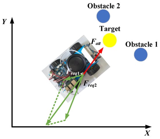
Figure 4.
The problem of non-reachable goal with obstacle nearby.
Therefore, the artificial potential field method is improved as follows: Obstacles generate two different repulsive forces on the mobile robot in two directions, one of which has the same direction as before, and a repulsive force from the mobile robot to the target point is added to the original foundation. After adding this repulsive force, the mobile robot moves under the combined action of two repulsive forces and one attraction force. The two abnormal situations mentioned above have been effectively resolved. The expression for the force generated by the improved artificial potential field method on mobile robots is as follows:
where n is the regulatory factor greater than 0.
Based on the improved artificial potential field method, the force acting on the mobile robot is shown in Figure 5.
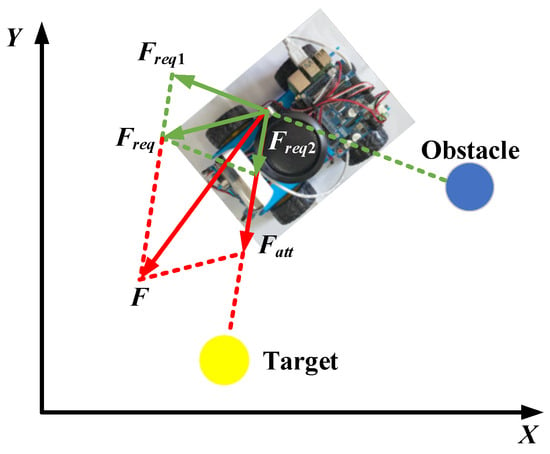
Figure 5.
The force acting on the mobile robot based on the improved artificial potential field method.
3.4. Control System Block Diagram
Based on the above research, the control block diagram of the mobile robot can be designed, which is shown in Figure 6.
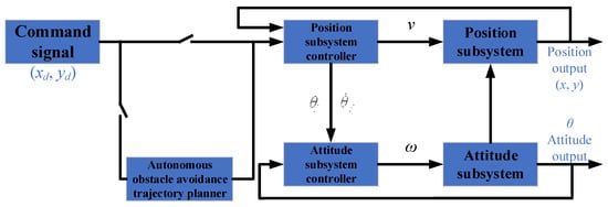
Figure 6.
Control block diagram of the mobile robot.
4. System Closed-Loop Stability Analysis
Assuming that there is a desired angle θd that satisfies trajectory tracking control, the kinematic model can be written as follows:
It can be seen that if θ and θd are inconsistent, they will inevitably affect the stability of the position closed-loop system. If the influence of the angle tracking error is considered and ideal control laws v1 and v2 are adopted, and and are taken at this time, the design can be carried out according to control law Equations (3) and (14), which can be rewritten as follows:
Since u1 and u2 are bounded, v is thus bounded, Equation (15) of the closed-loop system satisfies the global Lipschitz condition, and then xe and ye are bounded at any finite time for any initial state.
To prove that the closed-loop system is stable when , the Lyapunov function of the entire closed-loop system is taken as follows:
where .
Therefore, satisfying , , then
Considering , making , , then .
Considering , making , , then .
Therefore,
Considering the properties of trigonometric functions,
Considering the properties of sine functions, then .
Because of the exponential convergence of , then and are therefore exponentially convergent, and and are exponentially convergent, and .
Moreover,
where .
Therefore,
For any , there exists a finite time, , when and , making ; therefore, and converge to a compact set with radius in finite time, and remain within that compact set. Because when , , which is exponentially convergent, then and are exponentially convergent. Therefore, when , , , and and .
5. Experiment and Result Analysis
To verify the effectiveness and feasibility of the proposed method, experimental verification will be conducted in this section, taking the initial pose as [−2 3 0]. Taking the position command [xd yd] as xd = t, yd = sin(x) + x + 1. Moreover, a = 3.0, b = 3.0, p1 = 10.0, p2 = 10.0, k3 = 3.0, and η3 = 0.5. For the switching term of attitude control law Equation (7), the saturation function is applied, and the boundary layer thickness is taken as 0.10.
Based on the aforementioned theoretical research, the input and output of the differentiator and the control input signals v and ω can be obtained, which are shown in Figure 7, Figure 8 and Figure 9.
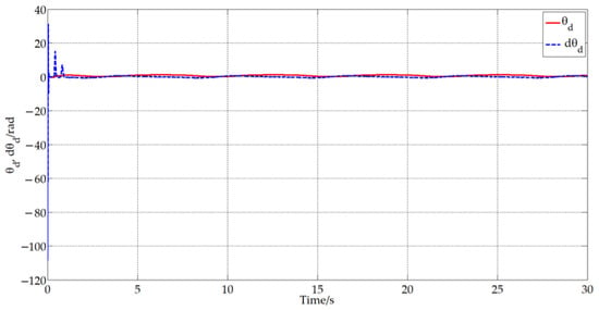
Figure 7.
The input and output of the differentiator.
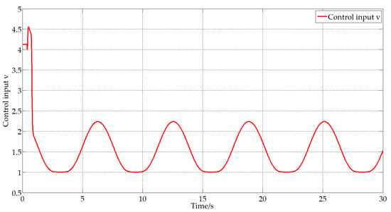
Figure 8.
The control input signal v.
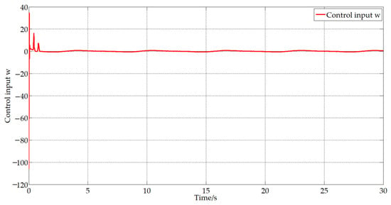
Figure 9.
The control input signal ω.
To further verify the effectiveness and feasibility of the proposed method compared to the existing methods, we introduce the A-star method and artificial potential field method. The trajectory tracking results obtained are shown in Figure 10, Figure 11, Figure 12 and Figure 13.
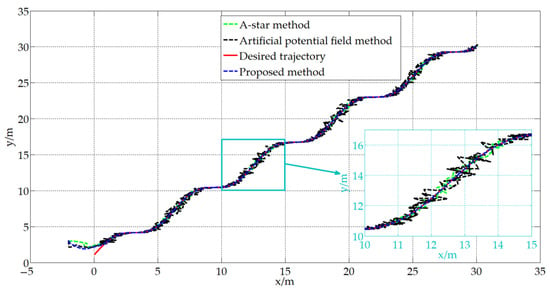
Figure 10.
Trajectory tracking.
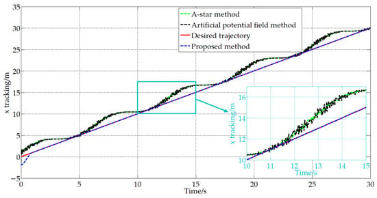
Figure 11.
Trajectory tracking in the x direction.
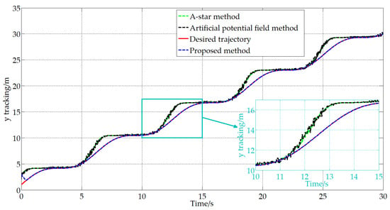
Figure 12.
Trajectory tracking in the y direction.
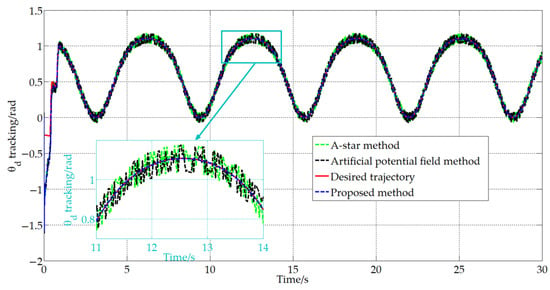
Figure 13.
Attitude trajectory tracking.
From Figure 10, Figure 11, Figure 12 and Figure 13, it can be seen that during the operation of the A-star method and the artificial potential field method, the trajectories of the mobile robot exhibit repeated vibrations and cannot fit the desired trajectory well, which results in low pose accuracy and unstable motion of the mobile robot. The reasons for this are as follows: For the A-star method, it has slow computational speed and large computational load, which lead to the mobile robot not being able to adjust its pose in a timely manner. And there is the problem of a mismatch between the desired pose and the current actual pose, resulting in the frequent adjustment of control commands and vibration during robot movement. In addition, the artificial potential field method is prone to local optimal solutions and the problem of a non-reachable goal with an obstacle nearby, leading to the mobile robot falling into the deadlock and being unable to reach the target point. And it is difficult for this model to handle the boundaries of infeasible areas, which may cause the mobile robot to oscillate back and forth between obstacles and target points. Compared to the A-star method and the artificial potential field method, the method proposed in this study is closer to the desired trajectory and has smoother trajectories, which can better meet the actual operational needs of mobile robots. To further verify the effectiveness and feasibility of the proposed method in practical applications, specific experiments will be conducted next.
5.1. Experiment of the Certain Trajectory without Obstacle
The certain trajectory used in this experiment was made by pasting black tape on the floor. The certain trajectory is specially crafted into an S-shaped shape with multiple bends, which is shown in Figure 14.
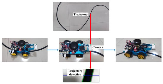
Figure 14.
Experiment of the certain trajectory without obstacle.
This study purposefully designed the trajectory as an S-shaped shape, which can not only examine the movement condition of the mobile robot in a straight line, but can also examine the turning of the mobile robot in two opposite directions of the curve. This can verify the good application performance of the control method proposed in this study, and the mobile robot can smoothly transition at turns without unstable motion situations in which the velocity and acceleration fluctuate intermittently.
From the final experimental results, it can be seen that after applying the A-star method and the artificial potential field method, the trajectory of the mobile robot exhibits repeated vibration and cannot fit the desired trajectory well. After applying the control method proposed in this study, the mobile robot not only moves very smoothly in the straight trajectory section, but also performs very smoothly in the turning trajectory section. The characteristic of motion is that when entering the turning trajectory section, the inner wheel slows down and the outer wheel speeds up. If the trajectory error increases during the turning process, the speed of the inner wheel will become slower under the influence of the trajectory error; on the contrary, the outer wheel will increase its speed as the trajectory error increases. When the error decreases, the change is also the opposite. In summary, with the application of the proposed control method, the mobile robot is able to intelligently and dynamically adjust the turn velocity and turn angle when changing trajectory. Compared to the A-star method and the artificial potential field method, the proposed control method can greatly improve the motion accuracy and stability of the mobile robot.
Moreover, in practical work, the motion trajectory is generally uncertain and there are usually multiple obstacles. To verify the effectiveness and feasibility of the proposed control method in scenarios with uncertain trajectories and multiple obstacles, the next experiment was conducted.
5.2. Experiment with Uncertain Trajectories and Multiple Obstacles
Firstly, five obstacle points and one target point were set, and simulation verification was conducted in MATLAB based on the proposed control method to verify the ability of trajectory planning and autonomous obstacle avoidance in the scenarios without certain trajectories and with multiple obstacles. The simulation result is shown in Figure 15.

Figure 15.
Trajectory planning and autonomous obstacle avoidance in MATLAB.
From the simulation results, it can be seen that the mobile robot has planned a trajectory from the starting point to the endpoint in the scenarios without certain trajectories and with multiple obstacles. And from the path of the mobile robot, it can be seen that the trajectory is smooth and without sudden changes. In theory, the mobile robot can smoothly avoid all obstacles and reach the target point. This theoretically verifies the effectiveness and feasibility of the proposed autonomous obstacle avoidance navigation scheme.
Next, experimental verification was conducted in actual scenarios. Figure 16 shows the experimental motion state diagram of the mobile robot in the scenarios without certain trajectories and with multiple obstacles. The mobile robot starts from the starting point and travels through multiple obstacles to reach the target point. The process runs accurately and smoothly, verifying the good trajectory planning and autonomous obstacle avoidance performance, which can reflect well the effectiveness and feasibility of the method proposed in this study.
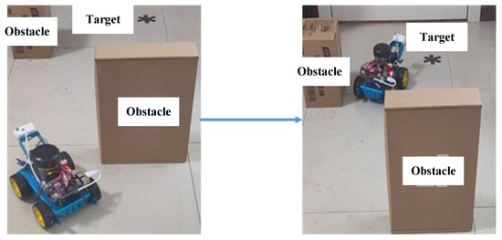
Figure 16.
Trajectory planning and autonomous obstacle avoidance in actual scenarios.
Specifically, when the mobile robot approaches the first obstacle in the left image of Figure 16, the repulsive force exerted by the obstacle on the mobile robot is much greater than the attraction force exerted by the target point on the mobile robot, and it begins to turn under the combined action of repulsive force, attraction force, position control law, and attitude control law. The mobile robot in the right image of Figure 16 is mainly subjected to the repulsive force of the second obstacle (as the first obstacle no longer affects the movement of the mobile robot, the influence of the obstacle behind the mobile robot is ignored) and the attraction force of the target point. Under the combined action of repulsive force, attraction force, position control law, and attitude control law, the mobile robot drives towards the target point.
6. Conclusions and Future Work
The aim of this study was to achieve stability and precision control and reduce the control cost for mobile robots. Based on the dual-loop trajectory tracking control and the improved artificial potential field method, an autonomous obstacle avoidance and trajectory planning control strategy with low computational complexity, high cost-effectiveness, and the ability to quickly plan a collision-free smooth trajectory curve is proposed in this article. The main superiority of the proposed method is that it not only has high trajectory tracking accuracy and good autonomous obstacle avoidance ability, but also has strong stability and real-time performance, which can be programmed within control cards and other small portable computational devices, and the proposed method is suitable for control engineering and robot applications in an actual scene. Moreover, to prove the effectiveness and feasibility of the proposed method, a simulation, experiment, and real-world application have been carried out. The results show that the proposed control method is capable of outperforming the existing control methods, i.e., the A-star method and the artificial potential field method. In the future, these techniques could be applied to the areas of autonomous vehicles, air traffic control, and group behavior simulation. Moreover, in practical applications, algorithm selection and adjustment need to be based on specific scenarios and requirements.
Optimizing the proposed control method under the premise of ensuring that it has high trajectory tracking accuracy, good autonomous obstacle avoidance ability, strong stability and real-time performance, a more concise algorithm structure, and is easy to transplant will be the key focus of future work. In addition, the influencing factors in actual applications and the laboratory are different. To further expand the practical application value, it is necessary to focus on how to connect the method proposed in this study with practical engineering in an actual working environment in future work.
Funding
This research was funded by the National Science Foundation for Young Scientists of China (grant number: 52205015); the Fundamental Research Funds for the Central Universities (grant number: JUSRP121044); and the 2021 Jiangsu Shuangchuang (Mass Innovation and Entrepreneurship) Talent Program (grant number: JSSCBS20210859).
Data Availability Statement
Data is unavailable due to privacy or ethical restrictions.
Conflicts of Interest
The author declares no conflict of interest.
References
- Zheng, K.; Hu, Y.; Yu, W. A novel parallel recursive dynamics modeling method for robot with flexible bar-groups. Appl. Math. Model. 2020, 77, 267–288. [Google Scholar] [CrossRef]
- Zheng, K.; Zhang, Q.; Hu, Y.; Wu, B. Design of fuzzy system-fuzzy neural network-backstepping control for complex robot system. Inf. Sci. 2021, 546, 1230–1255. [Google Scholar] [CrossRef]
- Zheng, K.; Zhang, Q.; Peng, L.; Zeng, S. Adaptive memetic differential evolution-back propagation-fuzzy neural network algorithm for robot control. Inf. Sci. 2023, 637, 118940. [Google Scholar] [CrossRef]
- Ayawli, B.B.K.; Chellali, R.; Appiah, A.Y.; Kyeremeh, F. An Overview of Nature-Inspired, Conventional, and Hybrid Methods of Autonomous Vehicle Path Planning. J. Adv. Transp. 2018, 2018, 8269698. [Google Scholar] [CrossRef]
- Cowlagi, R.V.; Tsiotras, P. Curvature-Bounded Traversability Analysis in Motion Planning for Mobile Robots. IEEE Trans. Robot. 2014, 30, 1011–1019. [Google Scholar] [CrossRef]
- Huang, L. Velocity planning for a mobile robot to track a moving target—A potential field approach. Robot. Auton. Syst. 2009, 57, 55–63. [Google Scholar] [CrossRef]
- Lyu, D.S.; Chen, Z.W.; Cai, Z.S.; Piao, S.H. Robot path planning by leveraging the graph-encoded Floyd algorithm. Future Gener. Comput. Syst. Int. J. Escience 2021, 122, 204–208. [Google Scholar] [CrossRef]
- Qin, H.; Shao, S.; Wang, T.; Yu, X.; Jiang, Y.; Cao, Z. Review of Autonomous Path Planning Algorithms for Mobile Robots. Drones 2023, 7, 211. [Google Scholar] [CrossRef]
- Wei, H.; Wang, B.; Wang, Y.; Shao, Z.; Chan, K.C. Staying-alive path planning with energy optimization for mobile robots. Expert Syst. Appl. 2012, 39, 3559–3571. [Google Scholar] [CrossRef]
- Zhong, X.; Tian, J.; Hu, H.; Peng, X. Hybrid Path Planning Based on Safe A* Algorithm and Adaptive Window Approach for Mobile Robot in Large-Scale Dynamic Environment. J. Intell. Robot. Syst. 2020, 99, 65–77. [Google Scholar] [CrossRef]
- Zheng, K.; Hu, Y.; Wu, B.; Guo, X. New trajectory control method for robot with flexible bar-groups based on workspace lattices. Robot. Auton. Syst. 2019, 111, 44–61. [Google Scholar] [CrossRef]
- Liu, L.; Wang, B.; Xu, H. Research on Path-Planning Algorithm Integrating Optimization A-Star Algorithm and Artificial Potential Field Method. Electronics 2022, 11, 3660. [Google Scholar] [CrossRef]
- Li, J.; Liao, C.; Zhang, W.; Fu, H.; Fu, S. UAV Path Planning Model Based on R5DOS Model Improved A-Star Algorithm. Appl. Sci. 2022, 12, 11338. [Google Scholar] [CrossRef]
- Hong, Z.H.; Sun, P.F.; Tong, X.H.; Pan, H.Y.; Zhou, R.Y.; Zhang, Y.; Han, Y.L.; Wang, J.; Yang, S.H.; Xu, L.J. Improved A-Star Algo-rithm for Long-Distance Off-Road Path Planning Using Terrain Data Map. ISPRS Int. J. Geo-Inf. 2021, 10, 785. [Google Scholar] [CrossRef]
- Zhang, Z.; Jiang, J.; Wu, J.; Zhu, X. Efficient and optimal penetration path planning for stealth unmanned aerial vehicle using minimal radar cross-section tactics and modified A-Star algorithm. ISA Trans. 2023, 134, 42–57. [Google Scholar] [CrossRef] [PubMed]
- Alshammrei, S.; Boubaker, S.; Kolsi, L. Improved Dijkstra Algorithm for Mobile Robot Path Planning and Obstacle Avoidance. Comput. Mater. Contin. 2022, 72, 5939–5954. [Google Scholar] [CrossRef]
- Liu, L.-S.; Lin, J.-F.; Yao, J.-X.; He, D.-W.; Zheng, J.-S.; Huang, J.; Shi, P. Path Planning for Smart Car Based on Dijkstra Algorithm and Dynamic Window Approach. Wirel. Commun. Mob. Comput. 2021, 2021, 8881684. [Google Scholar] [CrossRef]
- Wang, J.; Li, Y.; Li, R.; Chen, H.; Chu, K. Trajectory planning for UAV navigation in dynamic environments with matrix alignment Dijkstra. Soft Comput. 2022, 26, 12599–12610. [Google Scholar] [CrossRef]
- Yu, L.; Jiang, H.; Hua, L. Anti-Congestion Route Planning Scheme Based on Dijkstra Algorithm for Automatic Valet Parking System. Appl. Sci. 2019, 9, 5016. [Google Scholar] [CrossRef]
- Dian, S.; Fang, H.; Zhao, T.; Wu, Q.; Hu, Y.; Guo, R.; Li, S. Modeling and Trajectory Tracking Control for Magnetic Wheeled Mobile Robots Based on Improved Dual-Heuristic Dynamic Programming. IEEE Trans. Ind. Inform. 2021, 17, 1470–1482. [Google Scholar] [CrossRef]
- Korayem, M.H.; Irani, M.; Charesaz, A.; Hashemi, A. Trajectory planning of mobile manipulators using dynamic programming approach. Robotica 2013, 31, 643–656. [Google Scholar] [CrossRef]
- Luy, N.T. Robust adaptive dynamic programming based online tracking control algorithm for real wheeled mobile robot with omni-directional vision system. Trans. Inst. Meas. Control. 2017, 39, 832–847. [Google Scholar] [CrossRef]
- Yoon, H.-S.; Park, T.-H. Motion planning of autonomous mobile robots by iterative dynamic programming. Intell. Serv. Robot. 2015, 8, 165–174. [Google Scholar] [CrossRef]
- Chu, Z.; Wang, F.; Lei, T.; Luo, C. Path Planning Based on Deep Reinforcement Learning for Autonomous Underwater Vehicles Under Ocean Current Disturbance. IEEE Trans. Intell. Veh. 2023, 8, 108–120. [Google Scholar] [CrossRef]
- Peng, Y.; Liu, Y.; Li, D.; Zhang, H. Deep Reinforcement Learning Based Freshness-Aware Path Planning for UAV-Assisted Edge Computing Networks with Device Mobility. Remote Sens. 2022, 14, 4016. [Google Scholar] [CrossRef]
- Wang, J.; Shim, V.A.; Yan, R.; Tang, H.; Sun, F. Automatic Object Searching and Behavior Learning for Mobile Robots in Unstructured Environment by Deep Belief Networks. IEEE Trans. Cogn. Dev. Syst. 2019, 11, 395–404. [Google Scholar] [CrossRef]
- Xiao, X.; Liu, B.; Warnell, G.; Stone, P. Motion planning and control for mobile robot navigation using machine learning: A survey. Auton. Robot. 2022, 46, 569–597. [Google Scholar] [CrossRef]
- Zhang, L.; Zhang, Y.; Li, Y. Path planning for indoor Mobile robot based on deep learning. Optik 2020, 219, 165096. [Google Scholar] [CrossRef]
- Luo, Q.; Wang, H.; Zheng, Y.; He, J. Research on path planning of mobile robot based on improved ant colony algorithm. Neural Comput. Appl. 2020, 32, 1555–1566. [Google Scholar] [CrossRef]
- Miao, C.; Chen, G.; Yan, C.; Wu, Y. Path planning optimization of indoor mobile robot based on adaptive ant colony algorithm. Comput. Ind. Eng. 2021, 156, 107230. [Google Scholar] [CrossRef]
- Lee, J.; Kim, D.-W. An effective initialization method for genetic algorithm-based robot path planning using a directed acyclic graph. Inf. Sci. 2016, 332, 1–18. [Google Scholar] [CrossRef]
- Liu, L.; Wang, X.; Yang, X.; Liu, H.; Li, J.; Wang, P. Path planning techniques for mobile robots: Review and prospect. Expert Syst. Appl. 2023, 227, 120254. [Google Scholar] [CrossRef]
- Chang, Z.; Zhang, Z.; Deng, Q.; Li, Z. Route planning of intelligent bridge cranes based on an improved artificial potential field method. J. Intell. Fuzzy Syst. 2021, 41, 4369–4376. [Google Scholar] [CrossRef]
- He, Z.; Chu, X.; Liu, C.; Wu, W. A novel model predictive artificial potential field based ship motion planning method considering COLREGs for complex encounter scenarios. ISA Trans. 2023, 134, 58–73. [Google Scholar] [CrossRef]
- Tian, Y.; Zhu, X.J.; Meng, D.S.; Wang, X.Q.; Liang, B. An Overall Configuration Planning Method of Continuum Hy-per-Redundant Manipulators Based on Improved Artificial Potential Field Method. IEEE Robot. Autom. Lett. 2021, 6, 4867–4874. [Google Scholar] [CrossRef]
- Soltani, A.; Tawfik, H.; Goulermas, J.; Fernando, T. Path planning in construction sites: Performance evaluation of the Dijkstra, A∗, and GA search algorithms. Adv. Eng. Inform. 2002, 16, 291–303. [Google Scholar] [CrossRef]
- Montiel, O.; Sepúlveda, R.; Orozco-Rosas, U. Optimal Path Planning Generation for Mobile Robots using Parallel Evolutionary Artificial Potential Field. J. Intell. Robot. Syst. 2015, 79, 237–257. [Google Scholar] [CrossRef]
Disclaimer/Publisher’s Note: The statements, opinions and data contained in all publications are solely those of the individual author(s) and contributor(s) and not of MDPI and/or the editor(s). MDPI and/or the editor(s) disclaim responsibility for any injury to people or property resulting from any ideas, methods, instructions or products referred to in the content. |
© 2024 by the author. Licensee MDPI, Basel, Switzerland. This article is an open access article distributed under the terms and conditions of the Creative Commons Attribution (CC BY) license (https://creativecommons.org/licenses/by/4.0/).