Abstract
This paper proposes a new dual-stator hybrid-magnet flux modulation machine (DS-FMHMM) for direct-drive applications, which employs NdFeB magnet excitation and Ferrite magnet excitation on the rotor and outer stator sides, respectively. With this design, the proposed DS-FMHMM can not only fully use the bidirectional flux modulation effect, but also effectively alleviate the magnetic saturation issue. The machine configuration is described, together with the operating principle. Then, the design parameters of DS-FMHMM are globally optimized for obtaining high torque quality, and the influence of magnet dimensions on torque is analyzed. To evaluate the merits of the proposed DS-FMHMM, the electromagnetic performances of machines under different magnet excitation sources are analyzed, and a comprehensive electromagnetic performance comparison of DS-FMHMM and two existing dual-stator flux modulation machines (DSFMMs) is developed.
1. Introduction
Permanent magnet synchronous machines (PMSMs) possess the merits of high efficiency and high-power density, widely used in various industrial applications, e.g., marine propulsion and electrical vehicles [1,2]. Generally, the combination of a PMSM and a gearbox is used to meet the high torque requirement [3]. However, the employment of a gearbox inevitably brings mechanical loss and acoustic and vibration issues. Thus, direct-drive machines are required [4,5,6]. Among the potential candidates, flux modulation PM machines (FMPMMs) [7,8,9] attract lots of attention. By utilizing the “flux modulation effect” [10,11], FMPMMs are able to produce rich modulated harmonics for obtaining high torque production. However, the low power factor is one of the major problems with the FMPMMs. An effective solution to improve the problem is to introduce a dual-stator structure [12,13], which can also offer the advantages of high space utilization and control flexibility. Generally, the dual-stator flux modulation PM machines (DS-FMPMMs) locate PMs on the rotor side alone or the stator side alone. In [14], a typical DS-FMPMM with rotor PM excitation, i.e., the dual-stator vernier PM machine, is proposed, which can provide the advantages of a higher torque density and higher power factor than the single stator counterpart. In [15], a complementary dual-stator split tooth vernier PM machine is proposed. By transforming the phase relationship between the outer and inner stator windings, the flux distribution symmetry is improved, which can effectively reduce the unbalanced force by 60% compared to the conventional dual-stator vernier PM machine. In addition, to facilitate heat dissipation of PMs and reduce demagnetization risk, several DS-FMPMMs with stator PM excitation are proposed. In [16], a dual-stator flux-switching PM machine is proposed, which can eliminate the even-order harmonics in flux linkage and improve back-EMF by taking advantage of the dual-stator structure. In [17], a dual-stator flux reversal PM machine with Halbach array PMs is proposed, which has improved PM utilization, high torque density and good overload torque capability by using the Halbach array PMs. However, the air-gap flux density working harmonics of the DS-FMPMM with a single-side PM structure are limited, which restricts the torque capability. To improve the torque capability, dual-stator dual-PM excited flux modulation machines (DS-FMDPMMs) are proposed [18,19,20], in which the PMs are located on both the rotor and stator sides to use the bidirectional flux modulation effect [21,22] to produce rich working harmonics. However, a high volume of PM usage in one machine could cause severe saturation issues, which weakens the machine’s performance.
To solve the aforementioned problem, this paper proposes a new dual-stator hybrid-magnet FMM (DS-FMHMM), which employs NdFeB magnet excitation and Ferrite magnet excitation on the rotor and outer stator sides, respectively. With this design, the proposed DS-FMHMM can not only fully use the bidirectional flux modulation effect, but also effectively alleviate the magnetic saturation issue. In addition, the proposed DS-FMHMM employing ferrite magnets instead of NdFeB magnets on the stator can effectively reduce the cost under the same machine volume. The structure of this paper is as follows. In Section 2, the machine configuration is described, together with the operating principle. In Section 3, the optimal machine design parameters are obtained through multi-objective optimization, and the key parameter influence analysis is carried out. In Section 4, the electromagnetic performance of the proposed DS-FMHMM under different magnet excitation sources are investigated using the finite element (FE) method, and the merits of the machine are evaluated by comparing its performance with existing DS-FMPMM.
2. Machine Configuration and Operating Principle
2.1. Machine Configuration
The configuration of DS-FMHMM is illustrated in Figure 1, in which a rotor is sandwiched by two stators. The outer and inner stators adopt the split-tooth structure and conventional semi-slot structure, respectively. Two ferrite magnets with identical polarity are embedded in the inner surface of each outer stator tooth, and the adjacent ferrite magnets are separated by the iron poles, which form a consequent pole (CP) PM arrangement. The iron poles in the outer stator can be used to modulate the magnetic field excited by rotor NdFeB magnet excitation. Moreover, the non-overlapping concentrated windings are wound around the teeth of the inner stator and outer stator to take advantage of short endings and low copper loss. Moreover, a cup-shaped rotor with NdFeB magnets and iron poles jointed together is used in DS-FMHMM. The NdFeB magnets on the rotor and the ferrite magnets on the stator are all magnetized with the radially outward directions.
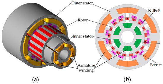
Figure 1.
The proposed DS-FMHMM topology. (a) 3-D view. (b) Cross-sectional view.
With the aforementioned design, the DS-FMHMM can effectively alleviate magnetic saturation and reduce the cost. Generally, a large volume of high magnetic energy product rare earth magnets used in one machine can cause severe saturation issues. To cope with the problem, the proposed design uses a low magnetic energy product ferrite magnet and a high magnetic energy product NdFeB magnet to form a hybrid excitation. In the proposed design, the NdFeB featuring high remanence is used to build the main magnetic field and the low magnetic energy product of the ferrite magnet takes advantage of eliminating the saturation issue. The B-H curves of NdFeB magnet and ferrite magnet are shown in Figure 2, and the materials and specifications of NdFeB and ferrite magnets used in the proposed DS-FMHMM are listed in Table 1. It can be seen that the remanence of NdFeB is almost three times that of ferrite magnet; therefore, the NdFeB magnet has no demagnetization risk caused by ferrite magnets. The ferrite magnet has a higher curie temperature than the NdFeB magnet, so it preserves its magnetization better at higher temperature levels [23].
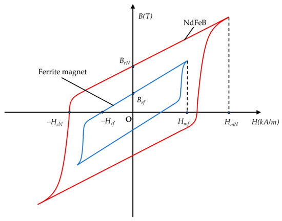
Figure 2.
The B-H curves of NdFeB and Ferrite magnets.

Table 1.
Materials and specifications.
2.2. Operating Principle
The operating principle of DS-FMHMM can explained in two ways, i.e., the flux linkage generation and flux modulation. The no-load flux line distribution and the corresponding variation of phase flux linkage with rotor position are shown in Figure 3 and Figure 4 respectively. It can be seen that a switched flux is generated with the relative movement of stators and rotors, which contributes to a bipolar phase flux linkage. When the rotor is at position (a), the magnetic flux excited by PM will pass through the stator teeth wound by the phase-A windings, and the maximum negative value of phase flux linkage can be obtained. When the rotor reaches position (b), there is no magnetic flux flow in the stator teeth wound by the phase-A windings, and thus the flux linkage of phase A comes to zero. Similarly, the flux linkage of phase A reaches the maximum positive value and zero at positions (c) and (d), respectively.
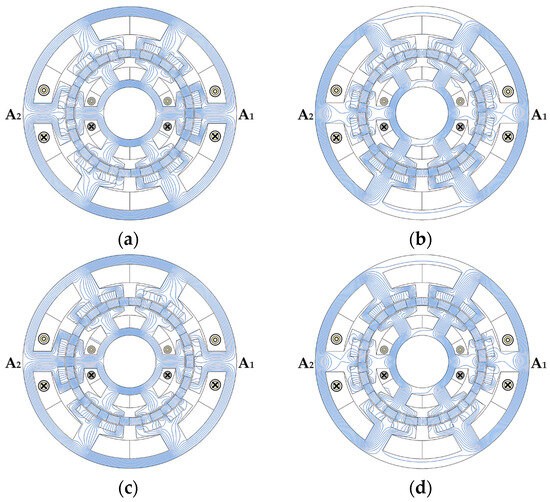
Figure 3.
The no-load flux line distribution of DS-FMHMM corresponding to four typical rotor positions (unit: electrical angle). (a) 0°. (b) 90°. (c) 180°. (d) 270°.
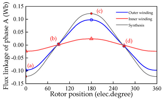
Figure 4.
Flux linkage characteristics of DS-FMHMM.
The DS-FMHMM is also working based on the bidirectional flux modulation effect. The outer stator teeth can be used to modulate the magnetic field excited by rotor NdFeB magnet excitation, and the rotor iron poles can be used to modulate the magnetic field excited by stator Ferrite magnet excitation. The air-gap flux density working harmonics of the machine are investigated by using a simplified magnetic motive force (MMF) permeance model. Without taking consideration of the stator Ferrite magnet excitation and the armature reaction of the outer and inner stators, the magnetic field generated by the NdFeB magnet excitation on the rotor can be expressed by [11]
where FNrm is the amplitude of the mth order harmonic excited by NdFeB magnet; Nr is the rotor pole pair number; m is a positive integer; ωr is the mechanical rotating speed of the rotor, θ is the rotor mechanical angle, and θr0 is the rotor initial angle. Then, the radial flux distribution generated by the NdFeB magnets on the rotor alone can be expressed as
where bNr0m is the Fourier coefficient. The outer stator teeth serving as modulators have a flux modulation effect on the harmonics generated by NdFeB magnet excitation. The relative permeance functions of the modulator are governed by [24]
where Λsi is the Fourier coefficients; Ns is the stator tooth number. Using the expressions (2) and (3), the resultant radial air-gap flux distribution is expressed as
Therefore, the PPN and the corresponding rotational speed of the spatial harmonics excited by NdFeB magnet excitation on the rotor are given by
Similarly, when the magnetic field is only excited by the Ferrite magnet excitation, the Fourier series expansion Fs of MMF generated by ferrite magnets is given as
where FFsn is the amplitude of nth order harmonics excited by Ferrite magnet excitation; Then, the radial flux distribution generated by Ferrite-magnets alone can be obtained by
where the bFs0n is the Fourier coefficients. The permeance function considering the rotor iron poles is written as
where the Λrj is the jth harmonic amplitude of the permeance function, and the ωr is the rotor angular speed. Thus, the resultant air-gap flux density can be written as
Using the expression (6)–(9), the PPN and the corresponding rotational speed of the spatial harmonics excited by the Ferrite magnet excitation on the outer stator are governed by
Based on Equations (5) and (10), to fully take advantage of the bidirectional flux modulation effect and obtain the highest torque, the PPN of inner and outer armature windings should be expressed by [25]
Then, the PPN and the corresponding rotational speed of the spatial harmonics excited by the armature reaction of the inner and outer stators are governed by
In order to achieve maximum torque production, the PPNs and rotational speeds of the modulated flux density harmonics excited by the stator and rotor PMs have to be equal to those excited by the armature reactions of the inner and outer stators. Based on (5), (10), and (12), the prominent working harmonics components that generate electromagnetic torque are listed in Table 2.
Table 2.
Working harmonics of the proposed DS-FMHMM.
3. Multi-Objective Optimization and Influence of Magnet Dimensions
3.1. Multi-Objective Optimization Design
Considering the potential applications of DS-FMHMM in direct drive, the objectives of maximum average torque (Tavg) and minimum torque ripple (Trip) are pursued via the multi-objective genetic algorithm (MOGA) [26] embedded in the FE software of JMAG. Figure 5 shows the geometric model of DS-FMHMM. During the optimization, the outer diameter, inner diameter, active stack length and air-gap length are fixed at 122 mm, 30 mm, 70 mm, and 0.5 mm, respectively, and the other design parameters of DS-FMHMM are set to design variables. In addition, the packing factor and current density are fixed at 0.5 and 5 A/mm2, respectively. The optimization flowchart is demonstrated in Figure 6. The optimization process can be described as follows:

Figure 5.
Key design variables and their geometric definitions.
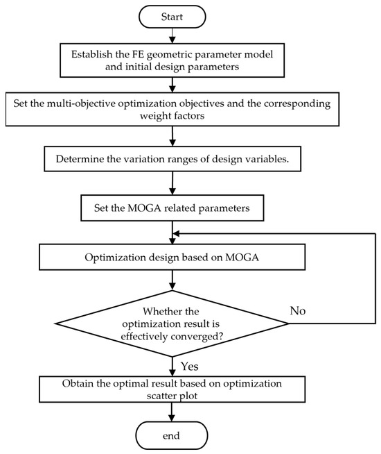
Figure 6.
Multi-objective optimization flowchart.
(1) Establish the FE geometric parameter model and initial design parameters. Before optimization, the FE geometric parameter model should be established first and the design parameters should be assigned initial values.
(2) Set the multi-objective optimization objectives and the corresponding weight factors. In this study, the maximum Tavg and minimum Trip are set as the optimization objects, and the Trip is defined as
where T(x)max and T(x)min are the maximum and minimum values of the steady-state instantaneous torque waveform, respectively. The weight factors of two optimization objects, i.e., the maximum Tavg and minimum Trip are set as 0.7 and 0.3, respectively;
(3) Determine the variation ranges of design variables. Based on the established model of the machine, the variation ranges of design variables to be optimized are chosen based on two aspects: 1. The constraint ranges are assigned to avoid conflicts and errors during the geometric modeling process. 2. The variation ranges of design variables associated with PM volume and the slot areas will be considered seriously based on the design experience [27]. For example, the PM height cannot be designed too thin, which will be difficult to manufacture. However, the PM height can also not be designed too thick, which will affect the torque performance. Therefore, to ensure the effectiveness of optimization results, the variation ranges of design variables during optimization are listed in Table 3.
Table 3.
Variation Range of design parameters.
(4) Set the MOGA-related parameters. The MOGA-related parameters including generation and population sizes should be properly set. To ensure that the optimization can converge efficiently, the population size and the number of generations should be sufficient. In this study, the generation and population sizes are set to 40 and 30, respectively.
(5) Optimization design based on MOGA. The basic process in the optimization design based on MOGA includes: a. create the initial individual based on the orthogonal array method and calculate the fitness value of each individual; b. compare the initial individuals and only the individuals with high fitness to the optimization objects are transferred into the population; c. create the 1st generation individuals; d. select individuals with better fitness from the 1st population to form the next generation population. e. the same process continues until the number of generations reaches 40.
(6) Obtain the optimal result based on an optimization scatter plot. Based on the above optimization progress, the optimization scatter plot can be obtained, as shown in Figure 7. By making a compromise between two optimization objects, the optimal solution is chosen as shown in Figure 7 (Tavg: 16.04 Nm, Trip: 3.17%), and the corresponding design parameters are listed in Table 4.
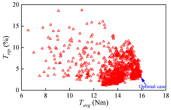
Figure 7.
Multi-objective optimization results.
Table 4.
The design parameters of optimal DS-FMHMM.
3.2. Influence of Magnet Dimensions on Torque Characteristics
The proposed DS-FMHMM using hybrid magnet excitation, and the dimensions of Ferrite magnet and NdFeB have a significant influence on electromagnetic performances. In this subsection, the influence of magnet dimensions on torque characteristics is investigated as shown in Figure 8. It should be noted that when one parameter is analyzed, the other parameters remain unchanged. As presented in Figure 8a, there exists an optimal hf to obtain the highest Tavg. This is mainly attributed to the influence of hf on both the PM MMF and equivalent air gap length. When the hf exceeds the optimum value, the Tavg turns to decrease due to the increase in the equivalent air gap length, which leads to a high magnetoresistance. Similarly, Figure 8b shows an identical trend to that in Figure 8a, where the Tavg first rises and then starts to decrease when hN arrives at 5 mm. From Figure 8c, the Tavg exhibits a parabolic trend with the θf increasing. As the increase in θf, the Tavg rises as a result of the increase in the PM MMF. However, when the θf is over 15 degrees, the Tavg starts to drop. This can be explained by the ferrite magnets on the stator being coupled to the iron poles: the growth of the PM arc will invade the space of iron poles, but when the iron pole is too narrow, the magnetic saturation tends to occur and is associated with the weakened flux modulation effect. The same trend can be observed in Figure 8d. It shows that the Tavg increases with θN increasing at first, but rapidly decreases when θf is over 25 degrees.
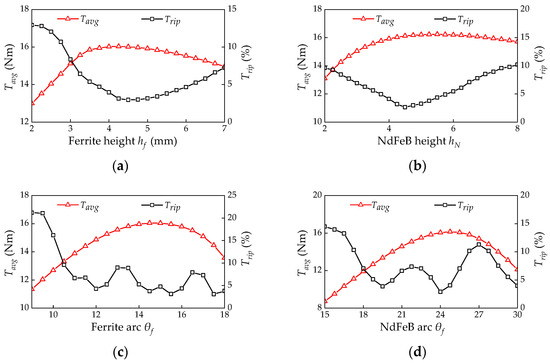
Figure 8.
Influence of magnet dimensions on torque characteristics. (a) Ferrite height hf. (b) NdFeB height hN. (c) Ferrite arc θf. (d) NdFeB arc θN.
4. Electromagnetic Performance Analysis and Comparison
4.1. Electromagnetic Performance Analysis
Based on the optimized parameters in Table 2, the no-load inner and outer air-gap flux density distributions and the corresponding harmonic spectra under different magnet excitation sources, i.e., Ferrite-magnet excitation, NdFeB magnet excitation, and hybrid-magnet excitation, inner and outer armature field are shown in Figure 9. It shows that the harmonic orders of inner and outer air-gap flux densities are consistent, and the use of hybrid magnets can be devoted to a series of harmonics. Amongst them, the main working harmonics contributing the torque production are the 1st (|Nr − 3Ns|), 5th (|Nr − 2Ns|), 7th (|Nr − 4Ns|), 17th (Nr), and 29th (Nr + 2Ns) harmonics, which agree with Table 1. Figure 10 shows the no-load flux line and flux density distributions of DS-FMHMM under different magnet excitation sources. It can be seen that using hybrid-magnet excitation can effectively increase the flux density of the stator and rotor, which is conducive to improving the machine’s performance. Moreover, the iron core of the stator and rotor is less prone to saturation due to the relatively lower flux density of Ferrite magnet excitation.
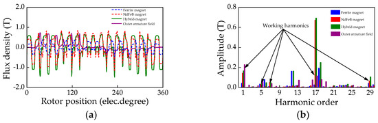
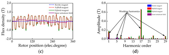
Figure 9.
Inner and outer air-gap flux densities of DS-FMHMM under different excitation sources. (a) Outer air-gap waveforms. (b) Outer air-gap harmonics spectra. (c) Inner air-gap waveforms. (d) Outer air-gap harmonics spectra.
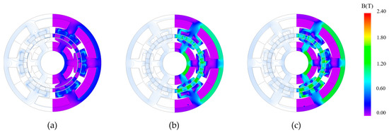
Figure 10.
No-load magnetic flux line and flux density distributions of DS-FMHMM under different magnet excitation sources. (a) Ferrite magnet excitation. (b) NdFeB magnet excitation. (c) Hybrid magnets excitation.
Figure 11 shows the rated torque waveforms of DS-FMHMM under different magnet excitation sources at the rated current of 6 Arms. Owing to the bidirectional flux modulation effect, the torque obtained using hybrid magnet excitation is 15.2% higher and 78.3% higher than that obtained by using NdFeB magnet excitation alone and Ferrite magnet excitation alone, respectively. However, its magnitude is less than the sum of the torque excited by the NdFeB magnet alone and the ferrite magnet alone. This is mainly attributed to a minor magnetic saturation at the edges of the stator core and rotor iron poles caused by using hybrid magnet excitation. Moreover, the Trip has a significant improvement by using hybrid-magnet excitation, which is reduced to 3.17%. As shown in Figure 12, the overload torque capability of the machine under different magnet excitation sources is analyzed. It is found that the machine using hybrid excitation can contribute to a relatively better overload torque capability. To evaluate the merits of the proposed machine in terms of alleviating the magnetic saturation, the flux densities of the proposed machine using hybrid magnet excitation and the machine using NdFeB magnet excitation on both the rotor and outer stator are compared. As shown in Figure 13, it is obvious that the rotor iron poles and stator iron poles of the machine using NdFeB magnet excitation alone tend to be saturated, but this phenomenon can be effectively improved when using hybrid magnet excitation.
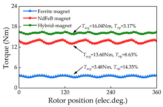
Figure 11.
Rated average torque waveforms of DS-FMHMM under difference magnet excitation.
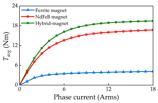
Figure 12.
The overload torque characteristics of DS-FMHMM under different magnet excitation sources.
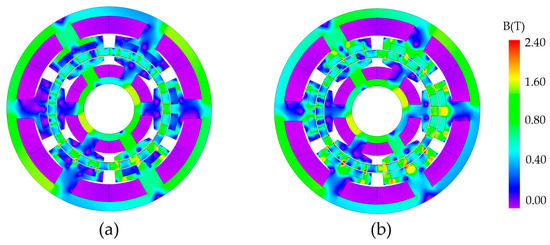
Figure 13.
Flux density distributions contours of DS-FMHMM under different magnet excitation sources at rated-load state. (a) Hybrid magnets excitation. (b) Dual NdFeB magnet excitation.
4.2. Electromagnetic Performance Comparison of DS-FMHMM and Two Existing DSFMMs
In order to confirm the superiority of DS-FMHMM, the electromagnetic performances of DS-FMHMM are compared with that of two existing DS-FMMs, i.e., a dual-stator vernier PM machine (DS-VPMM) and a dual-stator flux reversal PM machine (DS-FRPMM), and their topologies are illustrated in Figure 14. For a fair comparison, the DS-VPMM and DS-FRPMM are both globally optimized under identical inner and outer machine dimensions, stack length, packing factor, air-gap length and winding configuration with DS-FMHMM. Figure 15 shows the no-load back-EMF waveforms of three machines at the rated speed of 300 r/min. It can be seen that the back-EMF of DS-FMHMM is 59.7% and 69.1% higher than that of DS-VPMM and DS-FRPMM, respectively. However, the back-EMF total harmonic distortion (THD) of DS-FMHMM is higher than that of the two counterparts due to the large 3rd, 5th, 11th, and 19th harmonic components affected by the amplitudes of air-gap flux density harmonics, as presented in Figure 15b. Figure 16 shows the torque waveforms of three machines at the rated load state. It can be seen that DS-FMHMM can transmit 32.3% and 55.1% higher torque production than DS-VPMM and DS-FRPMM respectively. Furthermore, due to the higher back-EMF THD, the Trip of DS-FMHMM is higher than the other two counterparts. Moreover, Table 5 lists the other critical electromagnetic performances of the three machines. It is observed that due to the three machines having the same volumes, the DS-FMHMM accommodates the highest torque density, which is an important index for direct drive machines. Furthermore, the PM utilization of DS-FMHMM is 33.5% lower than DS-VPMM but 50.9% higher than DS-FRPMM, which is mainly attributed to the increased PM usage.
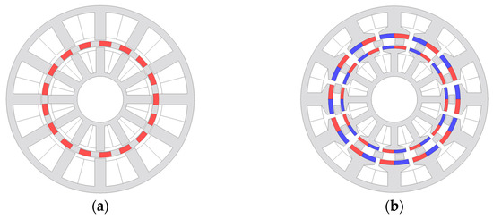
Figure 14.
Topologies of two existing DSFMM. (a) DS-VPMM. (b) DS-FRPMM.
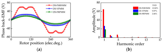
Figure 15.
No-load Back-EMF comparison of DS-FMHMM and the other two types of DSFMM. (a) Waveform. (b). Harmonic spectra.
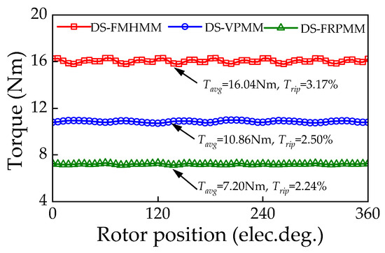
Figure 16.
Rated torque waveforms of DS-FMHMM and other two types of DSFMMs.
Table 5.
Critical electromagnetic performances of the three machines.
5. Conclusions
This paper proposes a new DS-FMHMM, which employs NdFeB magnet excitation and Ferrite magnet excitation on the rotor and outer stator sides, respectively. The operating principle of DS-FMHMM is analyzed from the flux linkage generation and flux modulation. It shows that DS-FMHMM using hybrid magnet excitation can enjoy rich working harmonics based on the bidirectional flux modulation effect. The multi-objective optimization design is carried out for obtaining high Tavg and low Trip, and the magnet dimensions of ferrite magnets and NdFeB magnets have a significant influence on Tavg and Trip. The electromagnetic performances of DS-FMHMM under different magnet excitation sources are investigated. The results show that the machine using hybrid magnet excitation can contribute to a high Tavg, low Trip and good overload capability. Moreover, by comparing the electromagnetic performances of DS-FMHMM with two existing DSFMMs, it is found that the DS-FMHMM has 59.7% and 69.1% larger back-EMF, 32.3% and 52.1% higher torque density than DS-VPMM and DS-FRPMM, respectively, which is desirable for direct-drive applications.
Author Contributions
Software, X.Y.; Writing—original draft, Y.M.; Writing—review & editing, H.W.; Supervision, X.B. All authors have read and agreed to the published version of the manuscript.
Funding
This work was supported by the National Science Foundation of China under Grant 62273211.
Data Availability Statement
The data that support the findings of this study are available on request from the first author or corresponding author, upon reasonable request.
Conflicts of Interest
The authors declare no conflict of interest.
References
- Krings, A.; Cossale, M.; Tenconi, A.; Soulard, J.; Cavagnino, A.; Boglietti, A. Magnetic materials used in electrical machines: A comparison and selection guide for early machine design. IEEE Ind. Appl. Mag. 2017, 23, 21–28. [Google Scholar] [CrossRef]
- Zhu, Z.Q.; Howe, D. Electrical machines and drives for electric, hybrid and fuel cell vehicles. Proc. IEEE 2007, 95, 746–765. [Google Scholar] [CrossRef]
- Nerg, J.; Rilla, M.; Ruuskanen, V.; Pyrhonen, J.; Ruotsalainen, S. Direct-driven interior magnet permanent-magnet synchronous motors for a full electric sports car. IEEE Trans. Ind. Electron. 2013, 61, 4286–4294. [Google Scholar] [CrossRef]
- Wrobel, R.; Mellor, P.H. Design considerations of a direct drive brushless machine with concentrated windings. IEEE Trans. Energy Convers. 2008, 23, 1–8. [Google Scholar] [CrossRef]
- Lee, C.H.T.; Chau, K.T.; Liu, C.; Ching, T.W.; Chen, M. A new magnet less flux-reversal HTS machine for direct-drive application. IEEE Trans. Appl. Supercond. 2015, 25, 5203105. [Google Scholar] [CrossRef]
- Du, J.; Liang, D.; Liu, X. Performance analysis of a mutually coupled linear switched reluctance machine for direct-drive wave energy conversions. IEEE Trans. Magn. 2017, 53, 8108110. [Google Scholar] [CrossRef]
- Li, D.; Zou, T.; Qu, R.; Jiang, D. Analysis of fractional-slot concentrated winding PM vernier machines with regular open-slot stators. IEEE Trans. Ind. Appl. 2018, 54, 1320–1330. [Google Scholar] [CrossRef]
- Kim, B.; Lipo, T.A. Analysis of a PM vernier motor with spoke structure. IEEE Trans. Ind. Appl. 2015, 52, 217–225. [Google Scholar] [CrossRef]
- Zahid, A.; Khan, F.; Ahmad, N.; Sami, I.; Ullah, W.; Ullah, N.; Ullah, N.; Alkhammash, H.I. Design and analysis of dual mover multi-tooth permanent magnet flux switching machine for ropeless elevator applications. Actuators 2021, 10, 81. [Google Scholar] [CrossRef]
- Zhu, Z.Q.; Liu, Y. Analysis of air-gap field modulation and magnetic gearing effect in fractional-slot concentrated-winding permanent magnet synchronous machines. IEEE Trans. Ind. Electron. 2017, 65, 3688–3698. [Google Scholar] [CrossRef]
- Cheng, M.; Han, P.; Hua, W. General airgap field modulation theory for electrical machines. IEEE Trans. Ind. Electron. 2017, 64, 6063–6074. [Google Scholar] [CrossRef]
- Niu, S.; Chau, K.T.; Jiang, J.; Liu, C. Design and control of a new double-stator cup-rotor permanent-magnet machine for wind power generation. IEEE Trans. Magn. 2007, 43, 2501–2503. [Google Scholar] [CrossRef]
- Wang, H.; Zhu, H.; Ding, S.; He, C.; Jin, Z.; Wei, Z. A new hybrid magnet dual stator field modulation machine with different split ratios of stators. IEEE Trans. Magn. 2022, 58, 8105806. [Google Scholar] [CrossRef]
- Li, D.; Qu, R.; Xu, W.; Li, J.; Lipo, T.A. Design procedure of dual-stator spoke-array vernier machine permanent-magnet machines. IEEE Trans. Ind. Appl. 2015, 51, 2972–2983. [Google Scholar] [CrossRef]
- Huang, J.; Fu, W.; Niu, S.; Zhao, X. Analysis of a complementary dual-stator vernier machine with reduced non-working Harmonics for low-speed direct-drive applications. IEEE Trans. Energy Convers. 2023. early access. [Google Scholar] [CrossRef]
- Li, Y.; Bobba, D.; Sarlioglu, B. Design and performance characterization of a novel low-pole dual-stator flux-switching permanent magnet machine for traction application. IEEE Trans. Ind. Appl. 2016, 52, 4304–4314. [Google Scholar] [CrossRef]
- Ning, S.; Seangwong, P.; Siritaratiwat, A.; Khunkitti, P. A novel double stator hybrid-excited flux reversal permanent magnet machine with Halbach PM arrays. In Proceedings of the 2023 IEEE International Magnetic Conference—Short Papers (INTERMAG Short Papers), Sendai, Japan, 15–19 May 2023; pp. 1–2. [Google Scholar]
- Meng, Y.; Fang, S.; Li, Y.; Zhong, Y.; Qin, L. Design and analysis of new dual-stator flux modulated machines with dual-PM excitation. IEEE Trans. Ind. Appl. 2022, 59, 1383–1393. [Google Scholar] [CrossRef]
- Meng, Y.; Fang, S.; Wang, H.; Pan, Z.; Qin, L. Design and analysis of a new dual-stator consequent-pole flux reversal machine with triple-PM excitation. IEEE Trans. Magn. 2021, 57, 8105904. [Google Scholar] [CrossRef]
- Meng, Y.; Fang, S.; Pan, Z.; Liu, W.; Qin, L. Machine learning technique based multi-level optimization design of a dual-stator flux modulated machine with dual-PM excitation. IEEE Trans. Transport. Electrific. 2022, 9, 2606–2617. [Google Scholar] [CrossRef]
- Wang, Q.; Niu, S.; Yang, L. Design optimization and comparative study of novel dual-PM excited machines. IEEE Trans. Ind. Electron. 2017, 64, 9924–9933. [Google Scholar] [CrossRef]
- Xu, L.; Zhao, W.; Liu, G.; Ji, J.; Niu, S. A novel dual-permanent-magnet excited machine with non-uniformly distributed permanent-magnets and flux modulation poles on the stator. IEEE Trans. Veh. Technol. 2020, 69, 7104–7115. [Google Scholar] [CrossRef]
- Galioto, S.J.; Reddy, P.B.; EL-Refaie, A.M.; Alexander, J.P. Effect of magnet types on performance of high-speed spoke interior-permanent-magnet machines designed for traction applications. IEEE Trans. Ind. Appl. 2014, 51, 2148–2160. [Google Scholar] [CrossRef]
- Qiao, Z.; Zhang, Y.; Luo, J.; Fu, W.; Shao, D.; Cao, H. A Non-Permanent Magnet DC-Biased Vernier Reluctance Linear Machine with Non-Uniform Air Gap Structure for Ripple Reduction. Actuators 2023, 12, 7. [Google Scholar] [CrossRef]
- Wang, Q.; Niu, S.; Yang, L. Design optimization of a novel scaledown hybrid-excited dual permanent magnet generator for direct-drive wind power application. IEEE Trans. Magn. 2018, 54, 1–4. [Google Scholar]
- Yu, J.; Liu, C. Multi-objective optimization of a double-stator hybrid-excited flux-switching permanent-magnet machine. IEEE Trans. Energy Convers. 2019, 35, 312–323. [Google Scholar] [CrossRef]
- Sun, M.; Xu, Y.; Han, K. Structure and optimization design of cup winding permanent magnet synchronous machine in flywheel energy storage system. IEEE Trans. Magn. 2023, 59, 8100805. [Google Scholar] [CrossRef]


Disclaimer/Publisher’s Note: The statements, opinions and data contained in all publications are solely those of the individual author(s) and contributor(s) and not of MDPI and/or the editor(s). MDPI and/or the editor(s) disclaim responsibility for any injury to people or property resulting from any ideas, methods, instructions or products referred to in the content. |
© 2024 by the authors. Licensee MDPI, Basel, Switzerland. This article is an open access article distributed under the terms and conditions of the Creative Commons Attribution (CC BY) license (https://creativecommons.org/licenses/by/4.0/).