Article

Design and Simulation of a Seven-Degree-of-Freedom Hydraulic Robot Arm

College of Mechanical & Electrical Engineering, Hohai University, Changzhou 213022, China
*
Author to whom correspondence should be addressed.
Actuators 2023, 12(9), 362; https://doi.org/10.3390/act12090362
Submission received: 15 August 2023 / Revised: 9 September 2023 / Accepted: 12 September 2023 / Published: 14 September 2023
(This article belongs to the Special Issue Advanced Robots: Design, Control and Application—2nd Edition)

Abstract

:
The current reliance on manual rescue is inefficient, and lightweight, highly flexible, and intelligent robots need to be investigated. Global seismic disasters occur often, and rescue jobs are defined by tight timetables and high functional and intellectual requirements. This study develops a hydraulically powered redundant robotic arm with seven degrees of freedom. To determine the force situation of the robotic arm in various positions, the common digging and handling conditions of the robotic arm are dynamically simulated in ADAMS. A finite element analysis is then performed for the dangerous force situation to confirm the structural strength of the robotic arm. The hydraulic manipulator prototype is manufactured, and stress–strain experiments are conducted on the robotic arm to verify the finite element simulation’s reliability.

1. Introduction

Efficient and quick rescue operations in the aftermath of natural disasters such as earthquakes and mudslides are a complex issue. Rescue equipment can be broadly categorized into two types: search and rescue. While the search type is used to locate trapped individuals, the rescue type is designed to perform tasks such as grasping, handling, and shearing that would otherwise require manual labor. Robots are increasingly being used for rescue operations to improve work flexibility and expand the range of operations. Over the past decades, different types of rescue robots have been developed, such as snake-shaped search and rescue robots [1,2,3], bionic crawling search and rescue robots [4,5], wheel-footed robots with enhanced obstacle-crossing capabilities [6,7,8], aircraft-based rescue robots [9,10], rope-assisted climbing robots for applications in mountainous environments [11], and deformable robots for water rescue [12]. However, few of these robots have significant excavation and handling capabilities. Mitsubishi Heavy Industries developed a robot that could load 5 kg heavy objects and a robot that could load 10 kg heavy objects by adapting to a variety of environments, which are compact, flexible, and can enter narrow spaces [13]. Japan’s TMSUK developed the “Enryu T-53” [14]—a crawler-type double-robotic-arm robot with high load capacity and suitable for handling, capable of lifting 100 kg of weight with a single arm. Wolf et al. [15] of Carnegie Mellon University developed a rescue robot with a wheeled motion platform and a multi-degree-of-freedom extension robotic arm, and the bottom moving platform expands the operating range of the robot. Shandong University, in cooperation with Luban Machinery Technology Corporation, developed a lightweight multifunctional dual-arm rescue robot with an overall weight of less than 5 tons, which can realize a variety of remote rescue functions [16].
The weight and load capacity of the rescue robot are the most important performance indicators, and the robotic arm, as the main actuator of the robot, plays an important role in the rescue process. Optimizing the structure and size of the robotic arm, reducing its own weight, and improving its load to weight ratio under the premise of ensuring its load capacity can effectively reduce consumables and control production costs on the one hand, and reduce energy consumption and improve work efficiency on the other. There are various ways to optimize the robotic arm, which can be optimized and improved in terms of structure [17,18,19,20], material [21,22,23,24], and process [25,26,27], in particular, combining topology optimization with manufacturing processes [28,29,30]. Rout et al. [31] used evolutionary optimization methods for two-degree-of-freedom planar manipulators and four-degree-of-freedom SCARA manipulators to design dimensional parameters and weights, and the method minimized the sensitivity of disturbing factors affecting accuracy and repeatability to minimum. Zhou L et al. [17] from Aalborg University combined finite element strength analysis based on kinematic performance, dynamics requirements, and lightweight design of a five-degree-of-freedom robotic arm in terms of both drive chain and structural dimensions. Liu W [32] used the non-inferiority ranking genetic algorithm NSGA-II (non-dominated sorting genetic algorithm II) with bit matrix representation to optimize the topology for multiple objectives such as mass and load capacity for lightweighting.
In this study, a seven-degree-of-freedom hydraulic robotic arm for emergency rescue is proposed. A model of the robotic arm is built, and in order to reduce the weight of the robotic arm, 7075 aluminum alloy is used as the main body material. Milling is then used to remove any excess material from the robotic arm while still maintaining the strength of the device and ensuring that it meets the load premise of the ideal weight. This study builds the dynamics model under the two working scenarios of excavation and heavy lifting and explores the finite element statics under these two working scenarios in order to test the strength of the robotic arm in the actual operation. The accuracy of the results of the finite element analysis was then confirmed by conducting stress–strain testing on a robotic arm prototype. This paper is organized as follows: the second part introduces the design and basic parameters of the robotic arm; the third part introduces the dynamic simulation of excavation and the handling of heavy objects; the fourth part introduces the finite element analysis of these conditions; and the fifth part introduces the prototype and finite element experiments carried out.

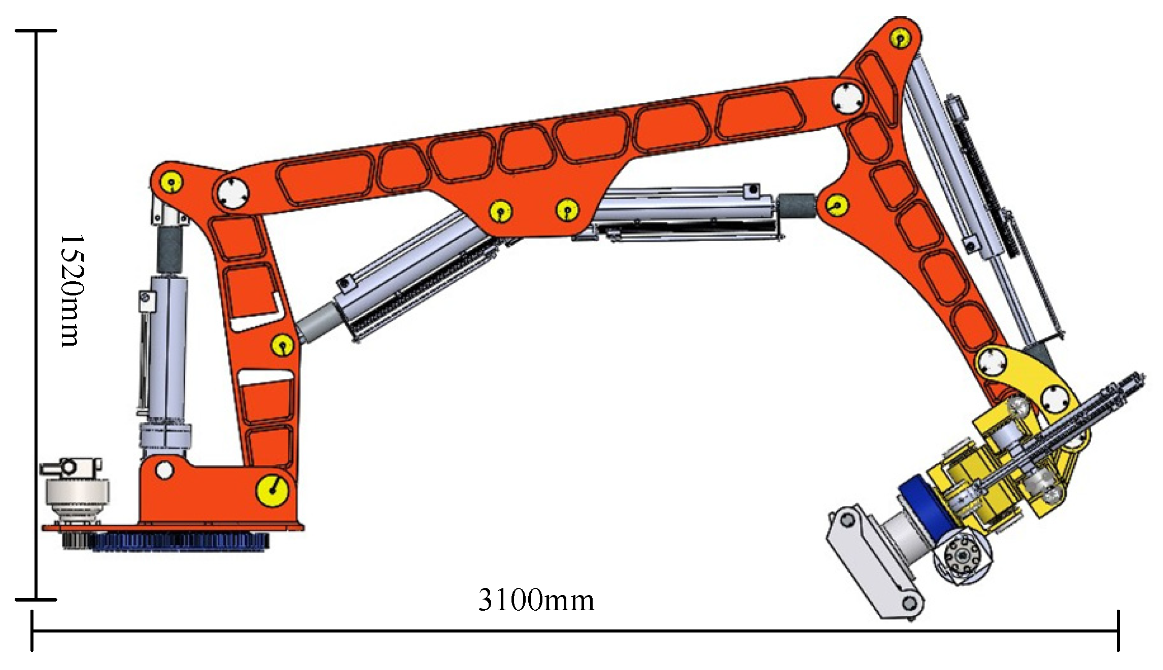
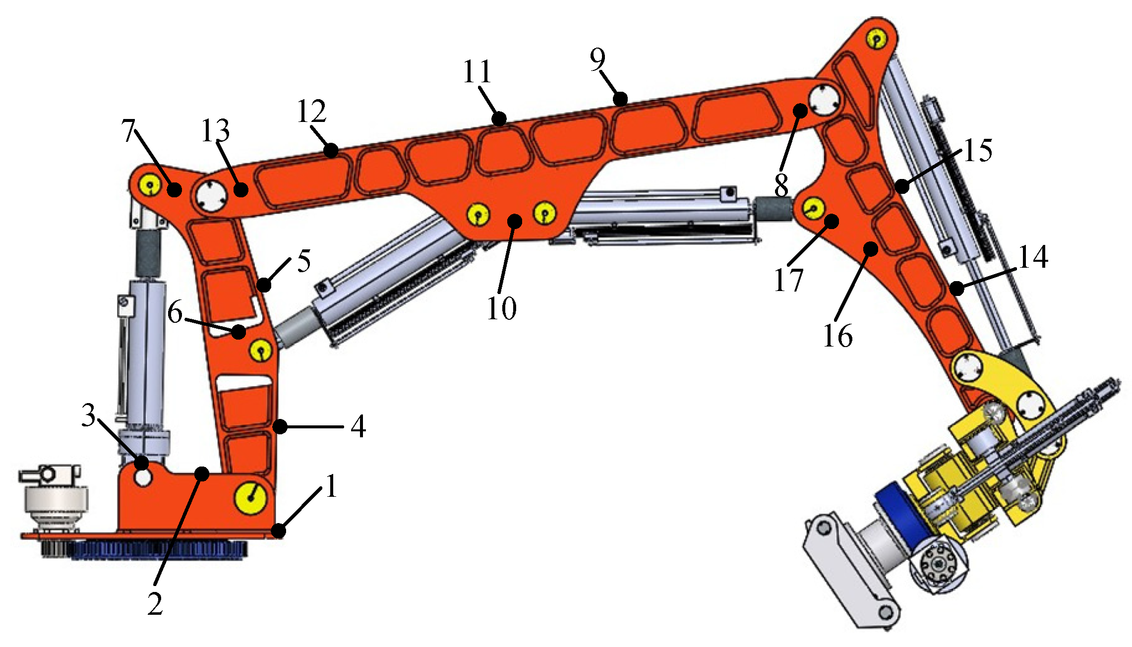
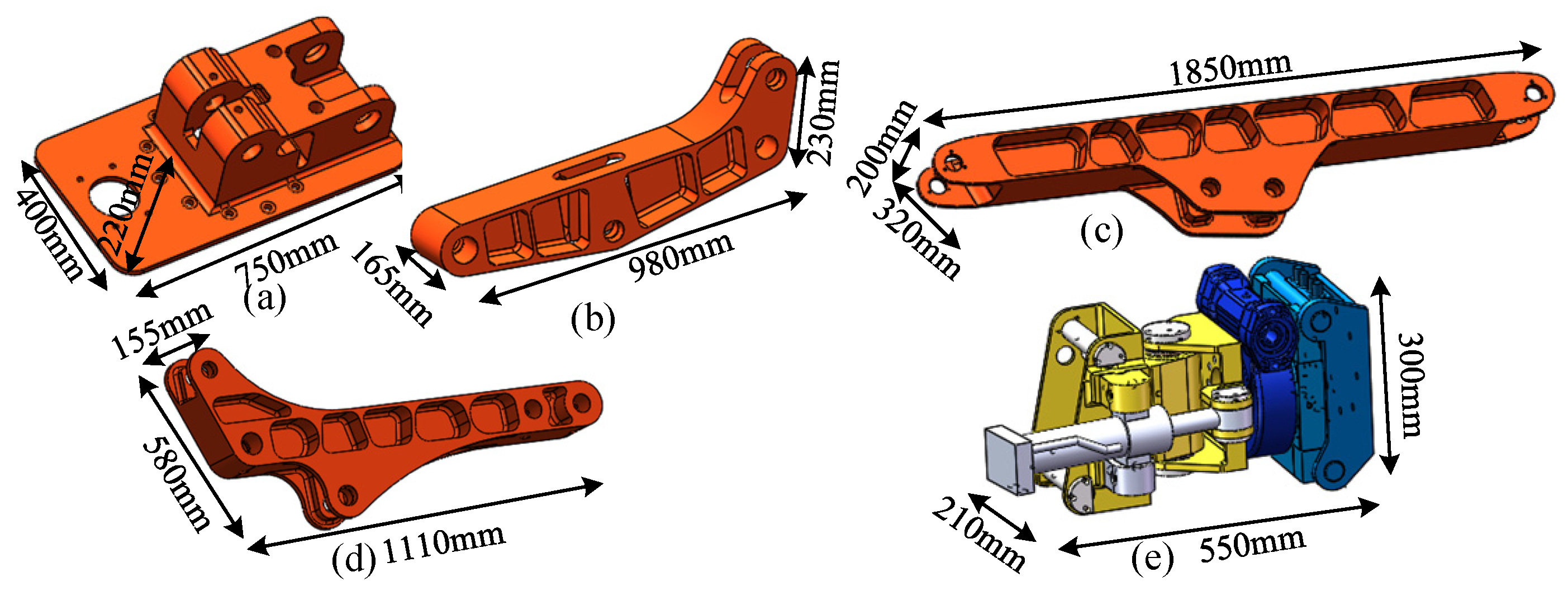
2. Structural Design of 7-DOFs Rescue Robotic Arm

The main challenges encountered during the process of its operation and performance requirements are as follows for earthquakes and other disasters that need to be specifically implemented after the rescue task to carry out the structural design of a rescue robotic arm, mainly including handling heavy objects, digging the ground, supporting the wall, and shear crushing and other conditions.
(1)
Because the homes of the current population are mostly made of reinforced concrete, earthquakes cause the walls to come off and crack. As a result, the robotic arm should be able to support and transport the collapsed wall with enough weight capacity.
(2)
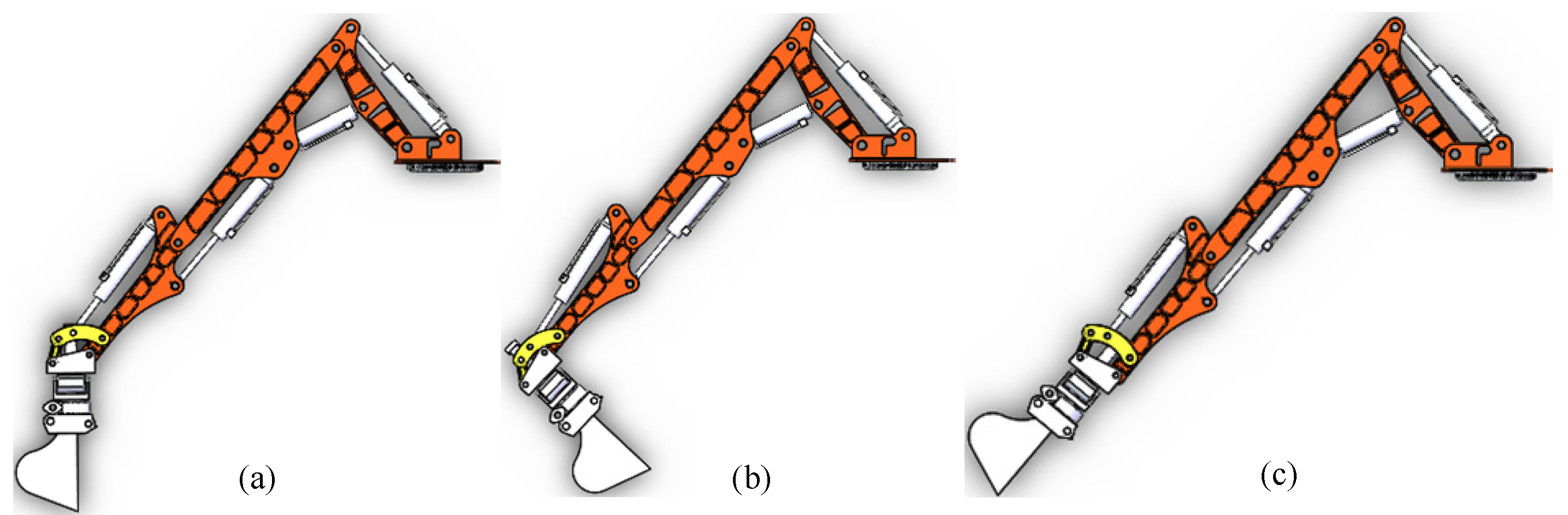
The post-earthquake debris formation is largely random, and the situation for rescue operations is very unstable. The robotic arm must have a high degree of flexibility as well as strong adaptive and movement capabilities for the complex road surface in order to respond to the complex and changing rescue needs. In order to rescue the trapped people from the small space, the robotic arm must be able to quickly adjust its position to the best rescue state.
(3)
After the earthquake, the rescue road is severely blocked, making it impossible for rescue supplies to be transported to the disaster site by land at first. In order to meet helicopter lifting requirements, the weight of the entire robot arm should be kept within a reasonable range.
Table 1 below displays the primary design criteria for the hydraulic rescue robot arm.
Contrarily, industrial robots have greater flexibility and finer operations, but their drawbacks are insufficient load capacity and more stringent environmental requirements. Conventional construction machinery and equipment have strong environmental adaptability and large load capacities, but their disadvantages are relatively bulky and inflexible activities. A hydraulic machinery arm with seven degrees of freedom is thus constructed as follows Figure 1 after combining the benefits and drawbacks of industrial machinery equipment and industrial robots. The rotary base, boom, two arms, three arms, rotary hammer joint, swing, and end rotary joint are the key parts.
Aluminum alloy 7075 is the primary material utilized to meet the robotic arm’s high strength and lightweight criteria. However, compared with steel, aluminum alloy material performs far poorer when it comes to welding. As a result, none of the robotic arm’s arms are machined and no welding technology is used. The arm makes extensive use of carving and excavation to ensure lightweight. Figure 2 depicts the key parts of the robotic arm, with (a)–(e) standing for the base, primary arm, second arm, third arm, and end wrist.

3. Mechanical Performance Analysis of Robotic Arm under Different Working Conditions

In the actual post-earthquake rescue process, the most typical working conditions of the rescue robotic arm are excavating and damaging the road and lifting heavy objects, and the robotic arm is prone to structural failure due to insufficient strength or excessive deformation under these two dangerous working conditions. In this section, the virtual prototype of the robotic arm is built, and the mechanical performance analysis of the working device is completed by using ADAMS (version 2019) simulation software for these two typical working conditions.

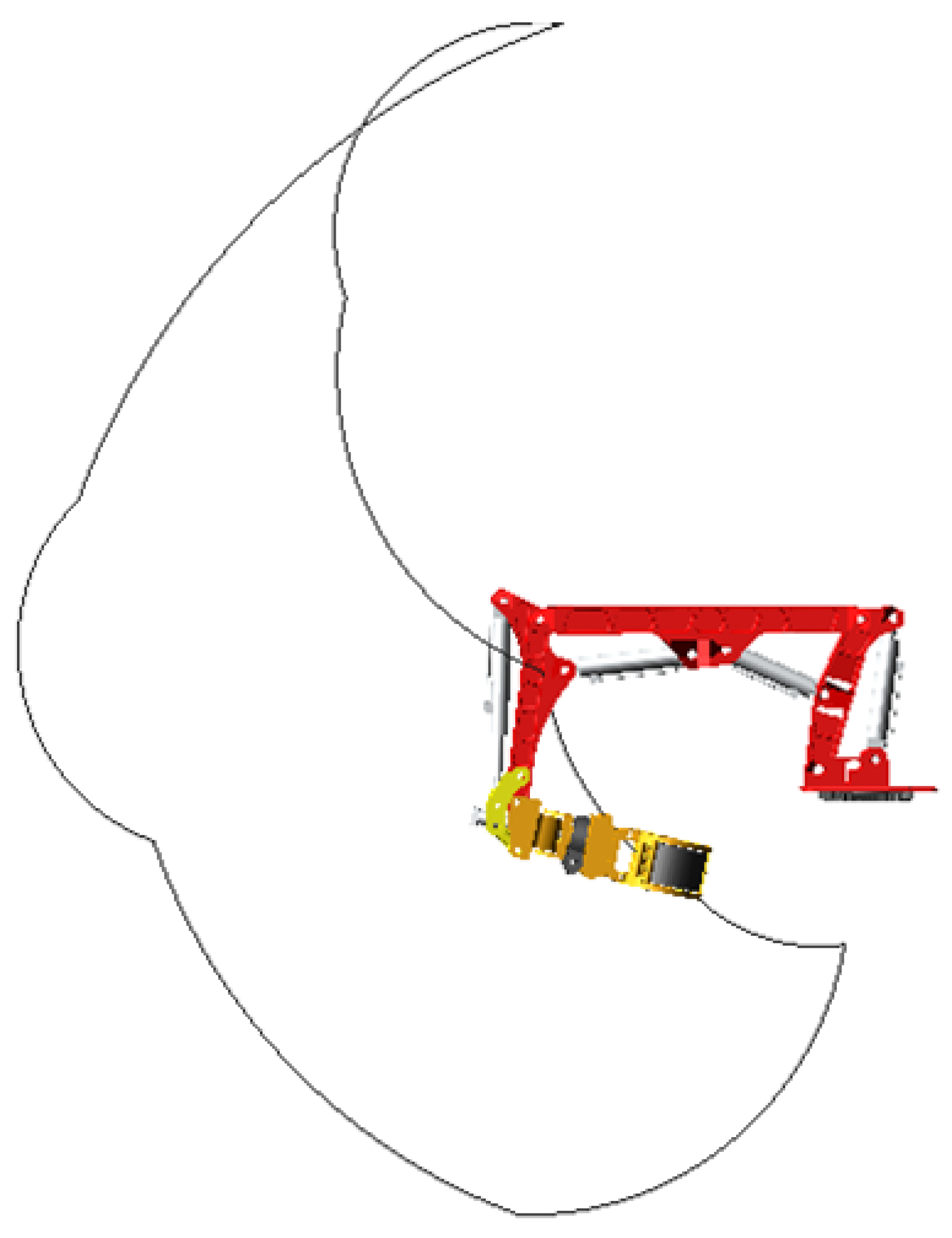
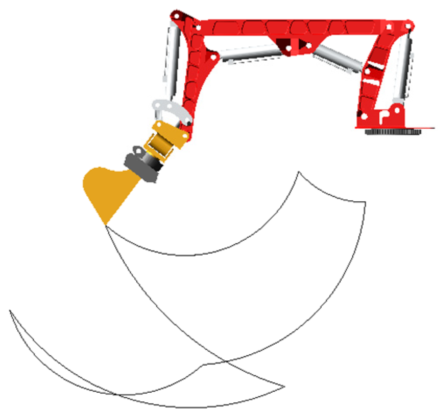
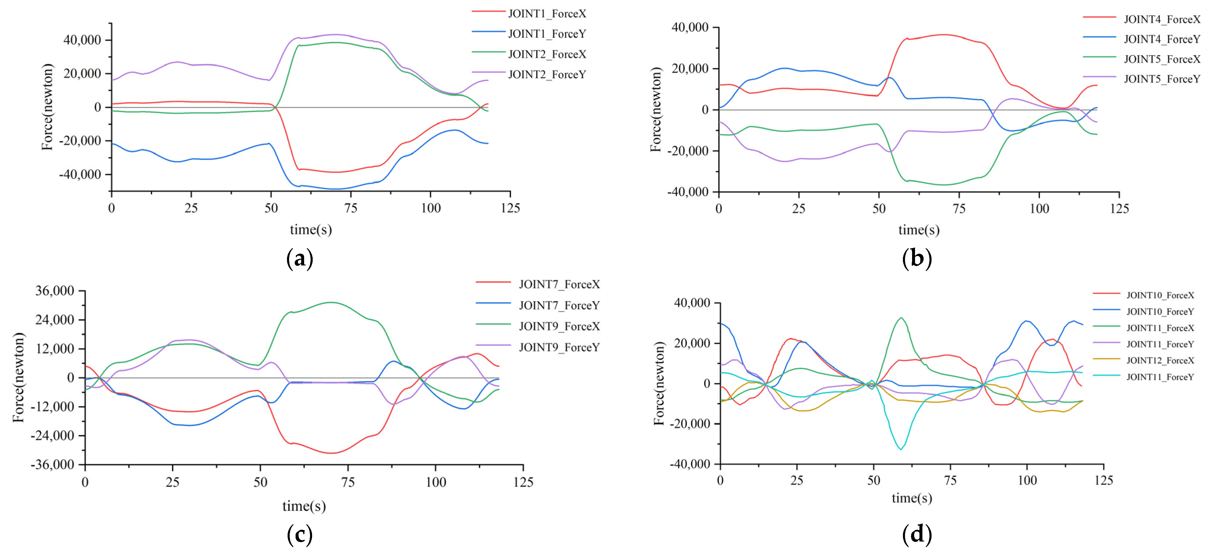
3.1. Dynamic Simulation of Robotic Arm under Excavation Conditions

When the robotic arm performs the task of digging and damaging the road, it will adjust its digging posture according to the changes of the digging target, and it needs to carry out simulation analysis for the most typical and extreme working conditions of the force on the robotic arm during the digging operation. If the arm can operate normally under this condition and there is no safety hazard, then other digging conditions will also meet the requirements of safe operation, so this subsection will simulate the most dangerous and extreme conditions of the force on the arm during digging.
When the mechanical arm is digging at the maximum depth, the force on the big arm and the second arm is the greatest, and it is at the weakest state of the working arm. At this time, the hydraulic cylinders of the big arm and the third arm are fully extended, the hydraulic cylinders of the second arm are fully retracted, and the bucket tip is vertically downward, as shown in Figure 3a. When the line between the tip of the bucket tooth and the articulation point of the third arm and the swing frame is perpendicular to the swing-frame cylinder, the torque on the swing-frame cylinder is the greatest at this time, as shown in Figure 3b. Special attention is needed, when the bucket tooth tip is in common line with the swing frame, swing-frame cylinder, and three arms, as shown in Figure 3c. At this time, the mechanical arm is in the posture of digging radius, and the digging depth is large; the form of force is more dangerous and an extreme situation, which needs to be taken into account during simulation.
According to the actual action requirements of excavation, and at the same time to include the above three extreme postures, the design of the excavation working conditions shown in Figure 4, first of all, the big arm and three-arm cylinders in turn extended to the state of full stroke, the second arm hydraulic cylinder fully retracted and maintained the state of no movement with drive, and, then, the swing-frame hydraulic cylinder from being fully retracted gradually extended, driving the bucket around the rotation point to dig, while the mechanical arm, in turn, went through the above three extreme postures and finally the three arms, big arm, and swing-frame hydraulic cylinder in turn retracted. The mechanical arm returned back to the original posture.
The main purpose of this simulation is to measure the force at the articulation point of each working arm, and the calculation and analysis found that the internal force of the wrist joint has almost no effect on the simulation results. Therefore, in order to simplify the operation, based on the ADAMS virtual prototype simulation model of the arm digging conditions, verified in the previous subsection, we use Boolean operations to combine the wrist joints into a whole. The tangential resistance gradually increases from 0 at 6.6 s, reaches the peak value of 8500 N after 4 s, and decreases to 0 after 2 s; the lifting resistance gradually increases from 0 at 6.6 s, reaches the maximum value of 2460 N after 6 s, and decreases rapidly at 20 s, and decreases to 0 after 1 s. Firstly, marker points are established at the position of the center of gravity of the bucket and the center point of the tooth tip, respectively, and the corresponding one-way force is added. The displacement driving function of each hydraulic cylinder and the change curve of the digging resistance are set by using STEP function, as shown in Table 2 and Figure 5.
Before running the simulation, in order to quickly identify and extract the force change curves at the target articulation points in the “ADAMS/Postprocessor” module and to make the following clearer, the articulation points of the robot arm are numbered and named as shown in Figure 6.
We set the simulation time to 22 s, step size 0.01, and ran the simulation. After the simulation, the force situation of each articulation point of the robot arm is viewed by the post-processing module. The load components of each joint’s articulation point in X-axis and Y-axis are shown in Figure 7, and (a) to (d) indicate the force of the articulation points of the base, large arm, second arm, and third arm joints, respectively.
Analysis of Figure 7 shows that the trend of the force at the articulation points of the base, large arm, and two arm joints is basically the same. Among them, the positive and negative force values only indicate the direction of the force. For the first 6.6 s, the big arm and the three-arm hydraulic cylinders were extended to the state of full stroke in turn, and the mechanical arm under the influence of the self-weight force is small. As the digging depth increases, the strength slowly rises. From the 6.6 s to start digging, due to the bucket contact with the ground at 7.2 s, the ground support force on the bucket offsets the influence of the mechanical arm self-weight, so that the force component at each articulation point gradually decreases between 6.6 s and 7.2 s to 0. With the increase of digging resistance, the force of each articulation point also gradually increases, and at 10.6 s, the digging depth and resistance reach the maximum, while the component of each joint articulation point in the X and Y axes is also close to the maximum. After the moment of 10.6 s, the digging resistance starts to decrease, and at the moment of 11.5 s, the force at each articulation point is again close to 0 under the compound action of cutting resistance and self-weight of the arm, and stops digging at 12.6 s, when the amount of material in the bucket reaches the maximum and the lifting resistance increases to another peak, and the force at each articulation point reaches the maximum at this time. After 12.6 s, hydraulic cylinders of the three arms start to shrink while driving the full-load bucket up, and the force on the articulation point of each joint is gradually reduced by the reduction of the force arm. At 20 s, the material is unloaded, the lifting resistance starts to decrease rapidly, and the force at each articulation point also decreases rapidly. At 21 s, the material is unloaded, and the swing hydraulic cylinder gradually retracts to the shortest state and drives the unloaded bucket to the initial attitude of the arm at 22 s, during which the force component at each articulation point remains basically unchanged.

3.2. Dynamic Simulation of Robotic Arm Handling Heavy Objects

Firstly, a workpiece with a weight of 200 kg is created in Solidworks and assembled with the end appliance gripper. Then, the end appliance bucket of the robot arm is deleted and replaced with the end appliance gripper, and finally a virtual simulation model of the robot arm under handling conditions is created in ADAMS according to the method described in the previous section. In order to accurately measure the force at each articulation point of the robot arm in the process of lifting the workpiece, the end gripper is set to carry the workpiece in the whole working range of the robot arm and to go through three extreme cases of highest position, horizontal position, and lowest position in turn. The initial position and the movement trajectory of the gripper finger end are shown in Figure 8. STEP function is used to set the displacement drive function of each hydraulic cylinder, as shown in Table 3 below. Firstly, the two-arm cylinder and the three-arm cylinder are set to extend to the full-stroke posture from the shortest state, and the swing-frame cylinder is retracted to the shortest state from the full-stroke state, at which time the mechanical arm reaches the highest point, then the mechanical arm passes through the horizontal position during the extension of the large-arm cylinder and swing-frame cylinder, and the mechanical arm passes through the lowest position when the two-arm cylinder retracts to the shortest posture, and finally the large-arm cylinder and the three-arm cylinder retract to the shortest state in turn, and the mechanical arm returns to the original posture.
We set the simulation time to 118 s, and got the force change curve of each articulation point of the robot arm under the handling condition, where the load components of each joint’s articulation point in X-axis and Y-axis are shown in Figure 9, and (a) to (d) indicate the force of the articulation points of the base, large arm, second arm, and third arm joints, respectively.
As can be seen from Figure 9, the change in patterns and trends of the base, big arm, and second arm amplitude curves are basically the same, and the force at the hinge point of the third arm is slightly more complicated. Before the first 26 s, the second arm cylinder and the third arm cylinder are extended in turn while making the workpiece rise slowly. As the center of gravity of the workpiece is farther and farther from the base, the moment of action on the base hinge point becomes bigger and bigger, and the force at each hinge point also rises slowly. At the moment of 26 s, the swing-frame cylinder starts to shrink while driving the workpiece close to the base, the moment gradually decreases so that the force at each articulation point slowly decreases until 49 s, and the robot arm moves to the highest position. After 49 s, the big arm cylinder starts to elongate, driving the workpiece away from the base while making the robot arm posture gradually approach the horizontal position; the workpiece and the wrist joint gravity on each articulation point produces the moment gradually increases, so that the force at the articulation point continuously increases. At the instance of 70 s, the end wrist joint is in common with the three arms and the second arm; at this time, the arm is in horizontal posture, the force component and amplitude of each articulation point reach the maximum value, and, after the horizontal position, the force at each articulation point gradually decreases. At 92 s, the hydraulic cylinder of the second arm is completely retracted; at this time, the arm is in the lowest position. After 92 s, the three-arm hydraulic cylinder starts to retract while driving the workpiece closer to the base. Due to the reduction of the action moment, the force at each articulation point slowly decreases, reaching 108 s, and the three-arm hydraulic cylinder completely retracts. The force at each articulation point reaches the minimum value, and then the big arm hydraulic cylinder starts to retract while driving the workpiece away from the base. Due to the increase of the action moment, the combined force at each articulation point increases, and, by 118 s, the mechanical arm returns to the original posture.

4. Finite Element Static Analysis of Key Components

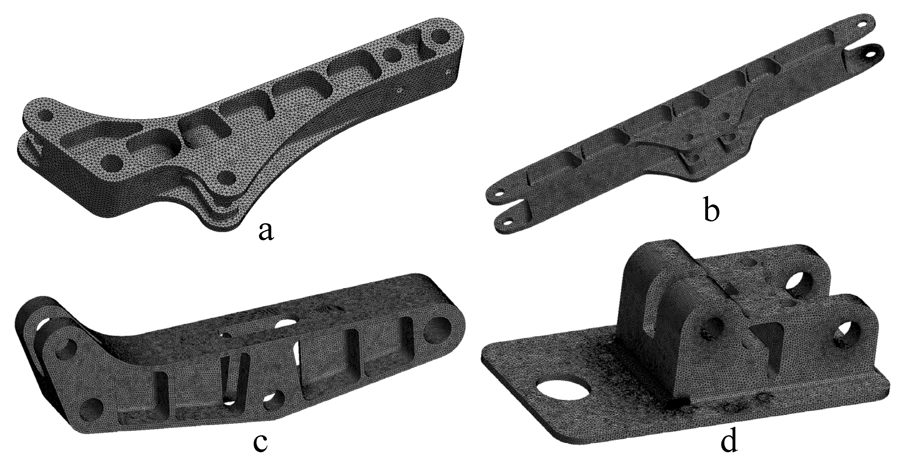
4.1. Pre-Processing of Robot Arm Finite Element Model

Although the seven-degrees-of-freedom redundant rescue robot arm designed in this topic is completed in Solidworks, the overall structure is more complex. Considering the aesthetic appearance of the robot arm and the requirements of some parts’ processing characteristics, many features such as rounded corners, small holes, chamfers, and tabs are retained at the early stage of structural design, and if these features are not simplified, stress singularities will be easily generated during analysis, which will lead to a large difference between the analysis results and the real value, and even the failure of the mesh division and the crash of the solver. Therefore, before the analysis, the analysis object should be reasonably simplified, the insignificant geometric features compressed or removed, and the reinforcement retained. Rounded corners and other geometric features have a greater impact on the calculation results, and special attention must be paid to the location where the analysis object is very likely to produce stress concentration to reduce the impact of stress concentration. The stress results of different nodes of the base at different mesh densities are shown in Figure 10. Therefore, when carrying out the mesh division, the region with greater influence on the analysis results uses the mesh control function to refine the mesh, and the quality should be high. When carrying out pre-processing work, it is necessary to ensure that the stiffness of the finite element analysis model before and after simplification is consistent; otherwise, it is likely to lead to a large difference between the analysis results and the actual value. The results of the mesh division of the three arms, two arms, large arm, and base are shown in Figure 11a–d, respectively.
In order to limit the degrees of freedom of each rigid body, the boundary conditions of the model need to be set before the analysis; according to the actual working conditions of the fixed end and free end of the robot arm, to add constraints and loads, the process is as follows:
(1)
Add reasonable restraint: The robot arm near the base member can be regarded as the fixed end, and near the end apparatus as the free end. Using the fixture function, a fixed hinge constraint is set on the selected axis hole surface to restrict the hinge point.
(2)
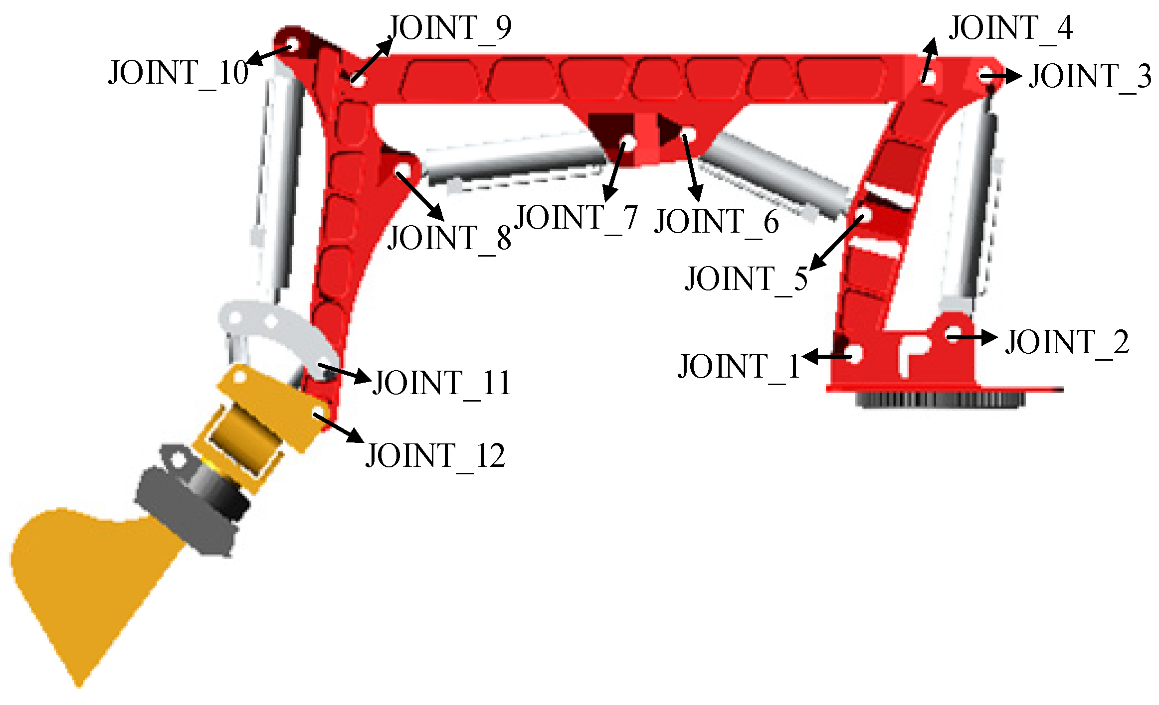
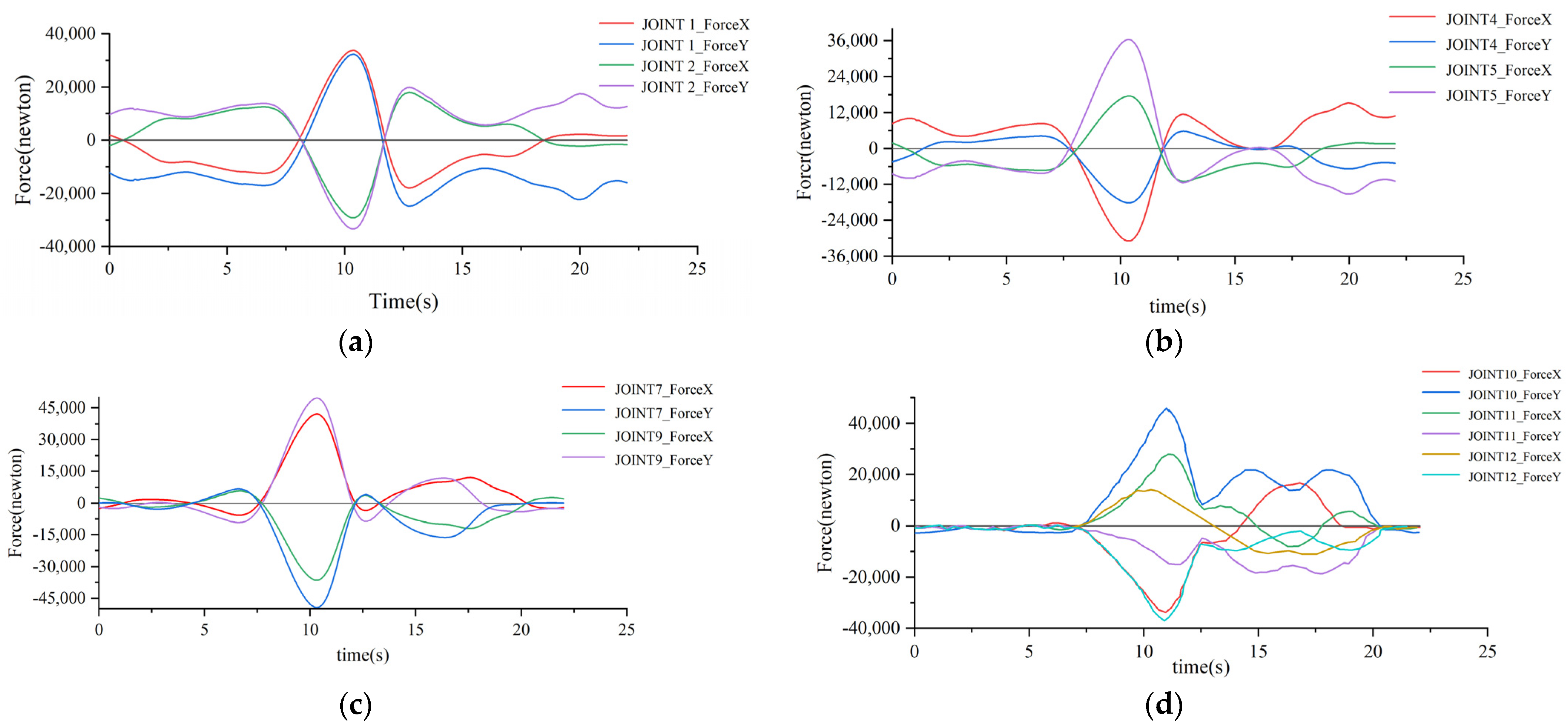
Applying load: Therefore, the bearing load is added to the pin hole at the free end. When assigning the load size, considering that each hole has two bearing surfaces, half of the combined force obtained from the motion simulation should be added to each bearing surface. Since the force at the hinge point is not constant, but fluctuates according to a certain rule, according to engineering experience, the fluctuation is in line with the parabolic distribution, so the distribution of load is more compounded with the actual working condition by choosing parabolic distribution. The mesh parameters for each component are shown in Table 4.

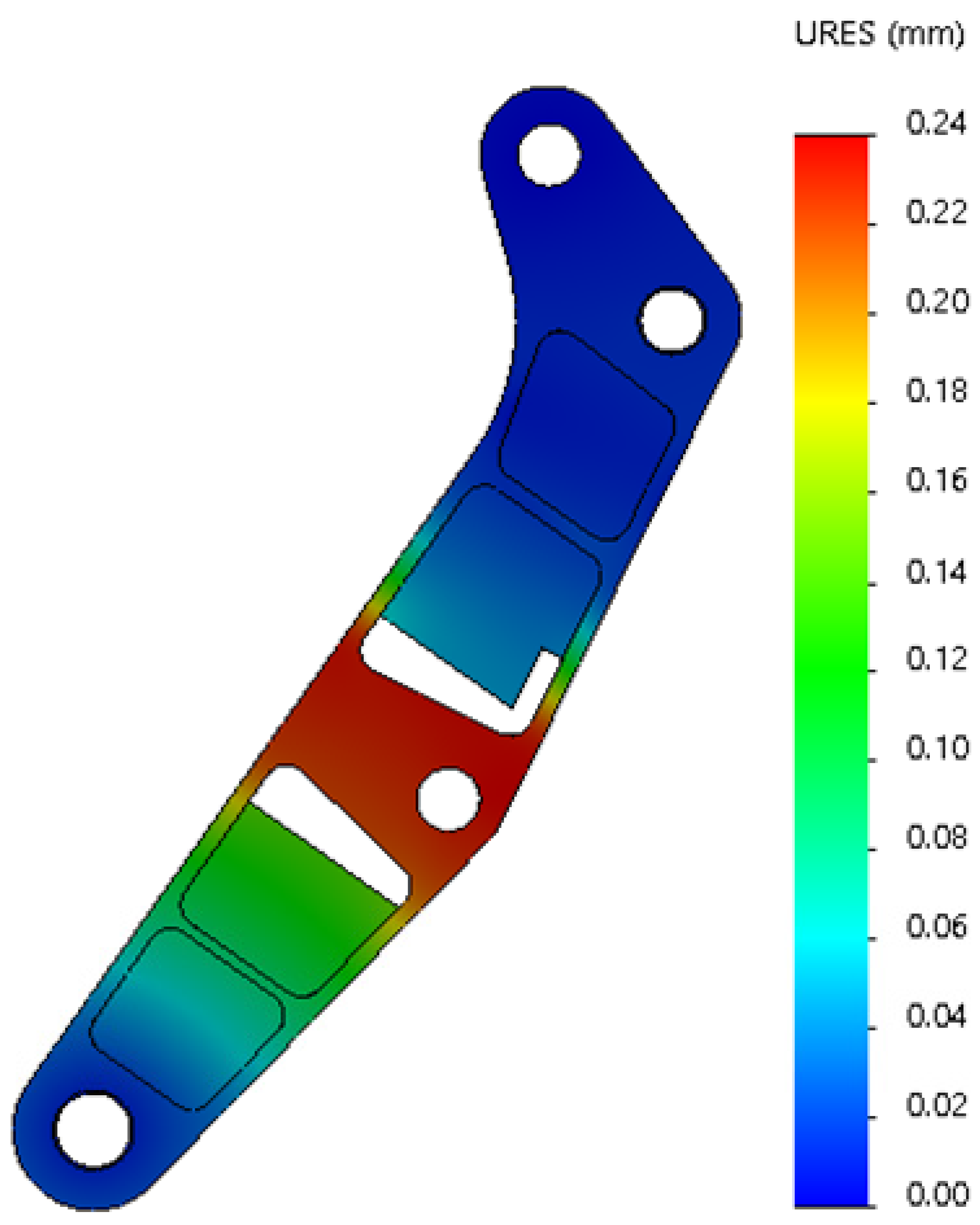
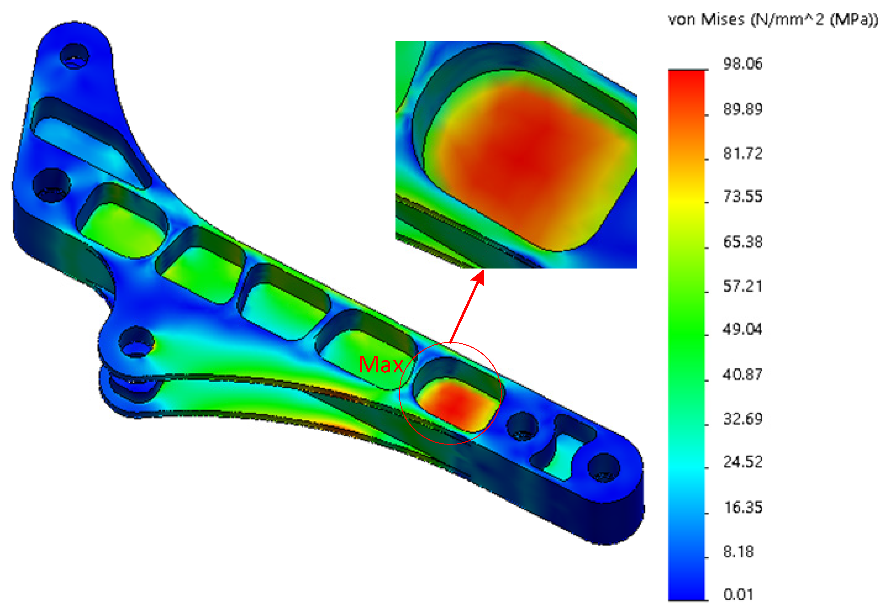
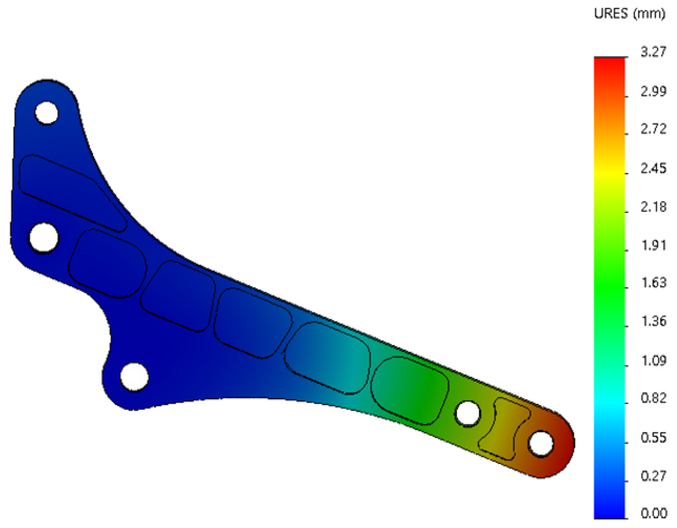
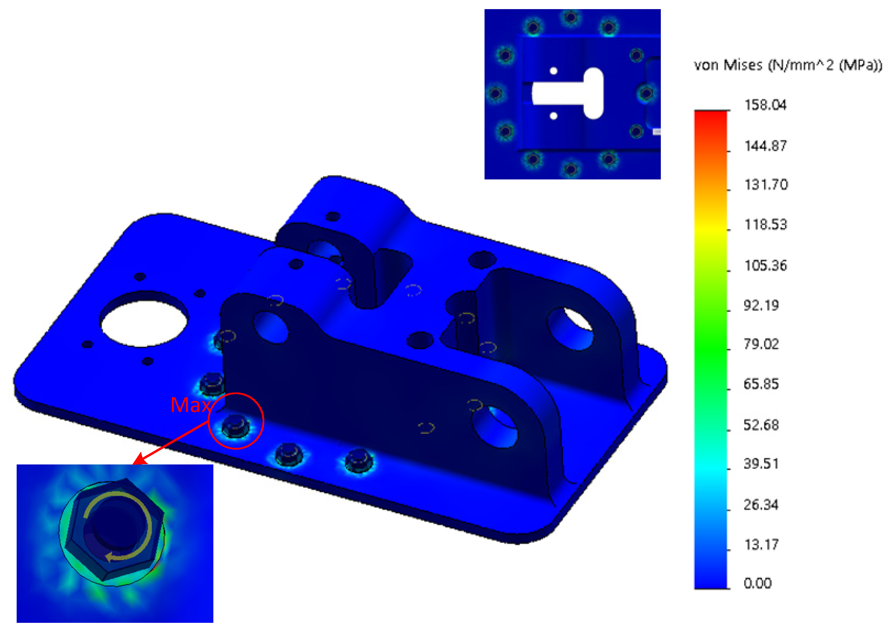
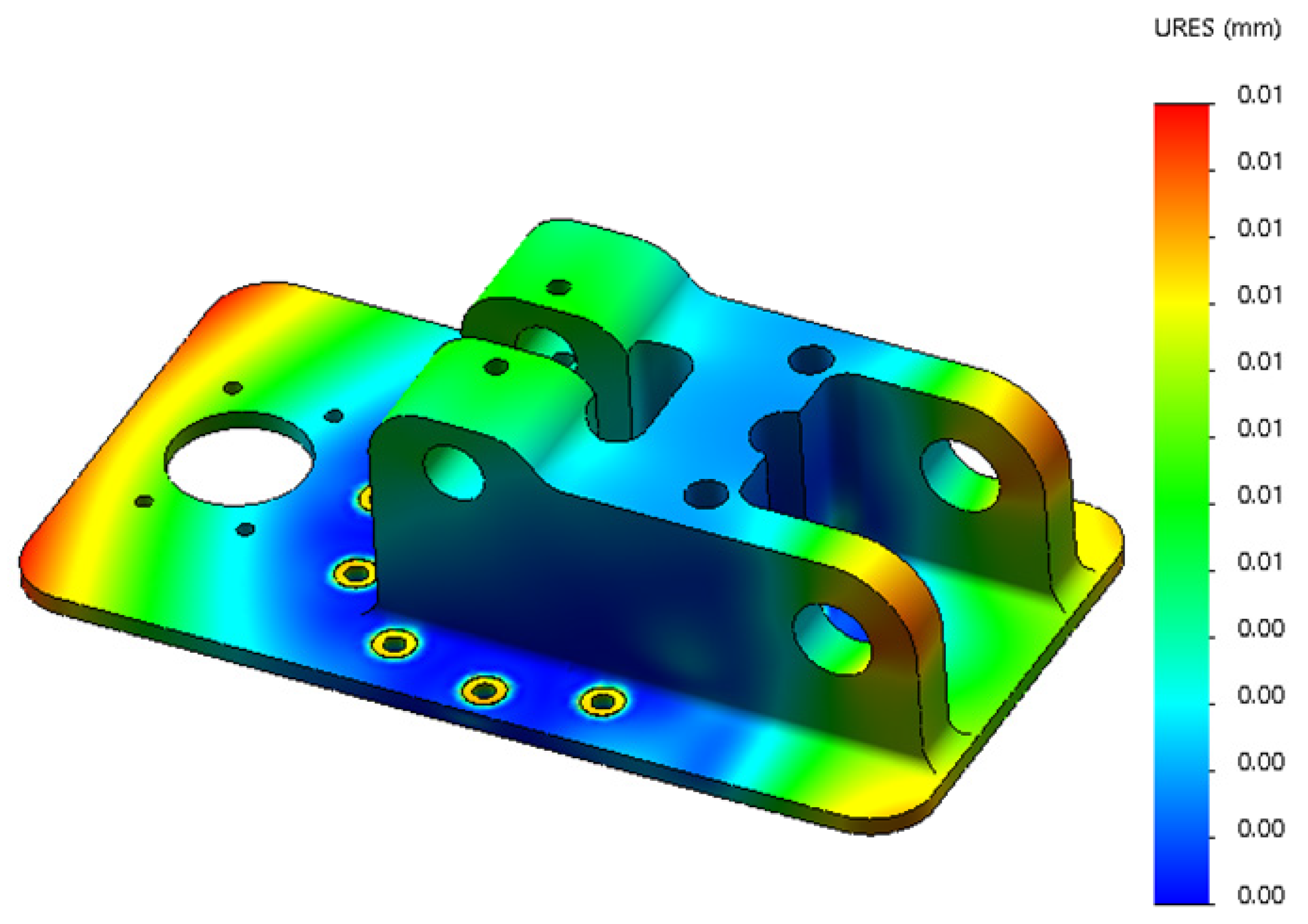
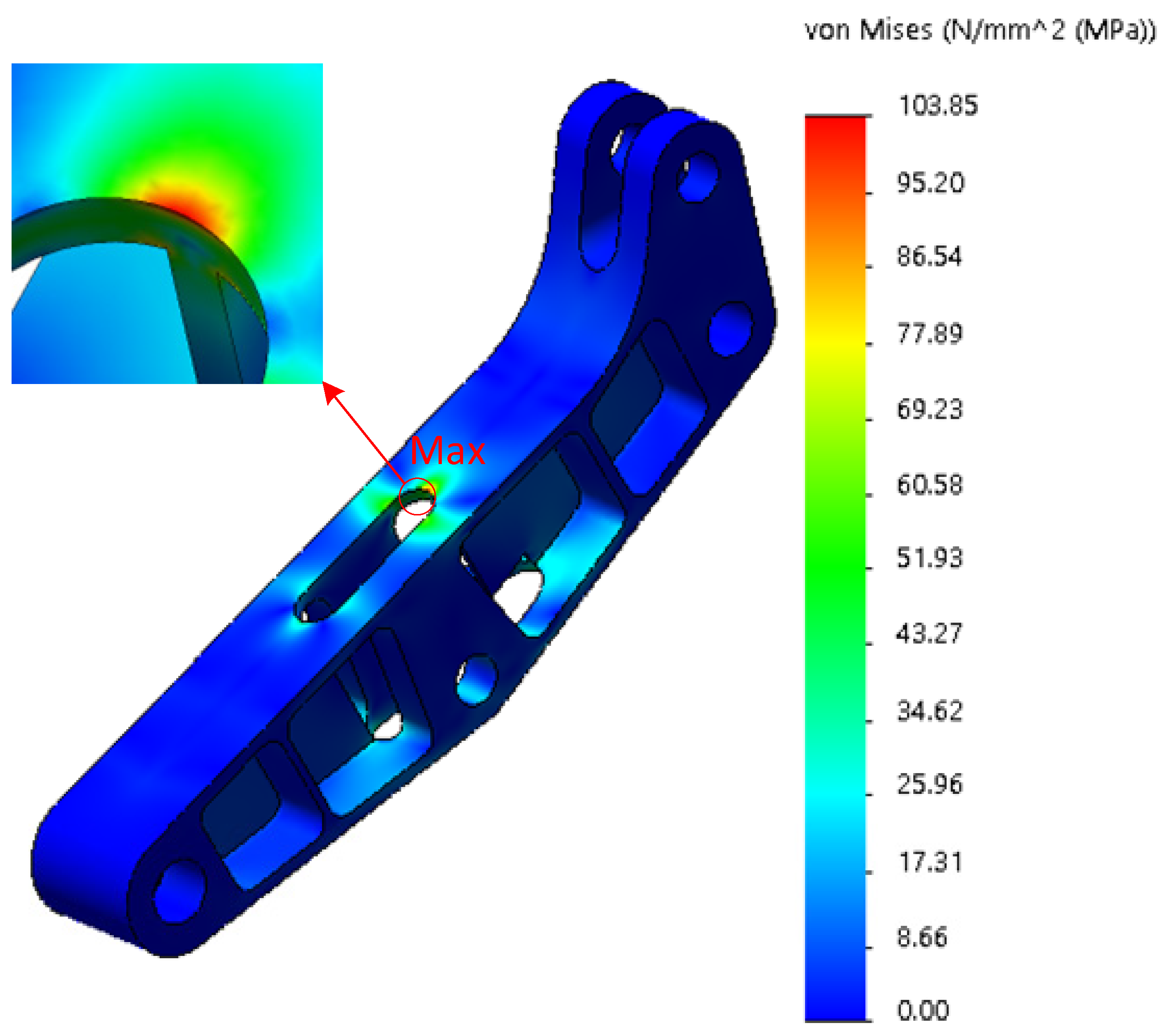
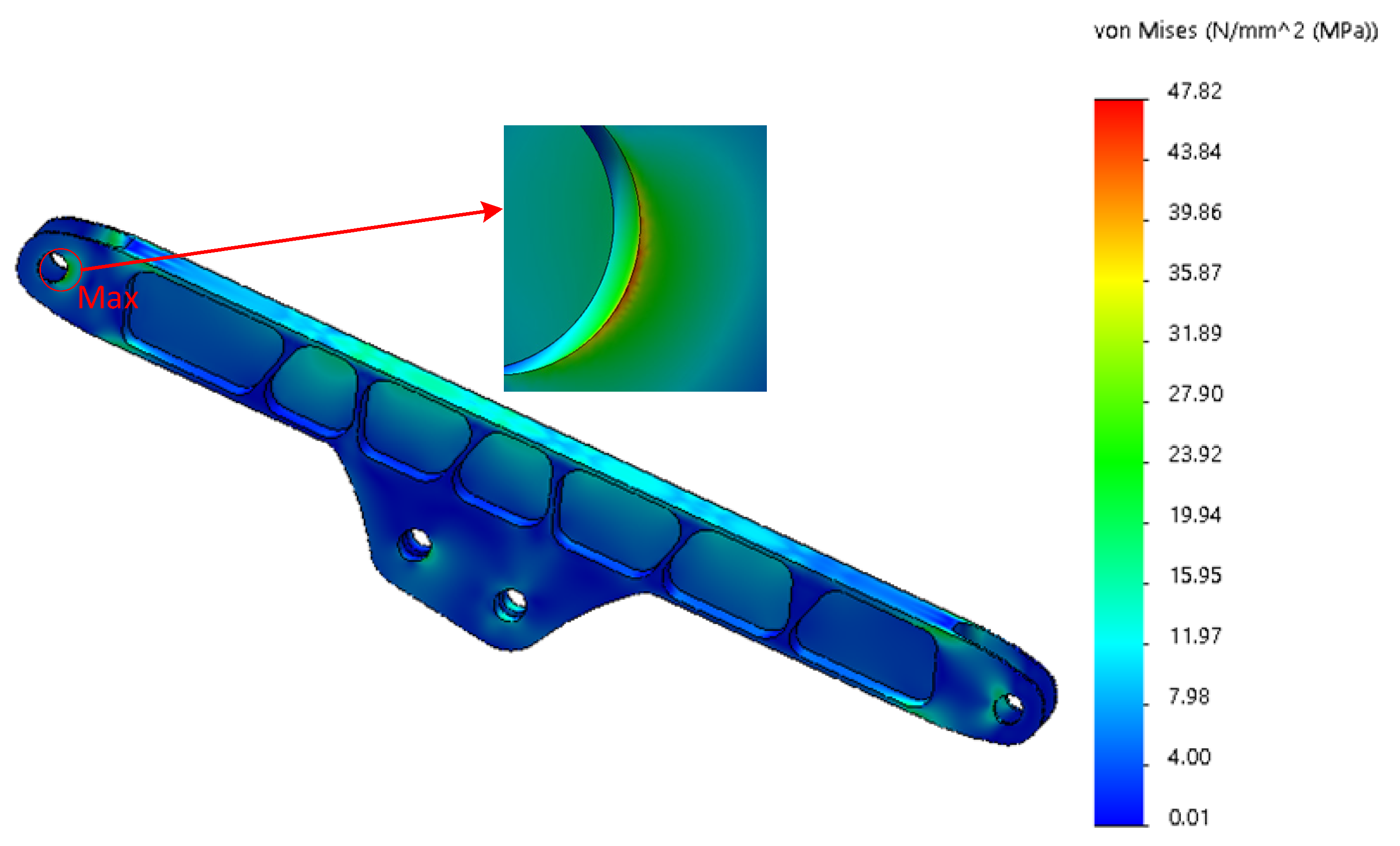
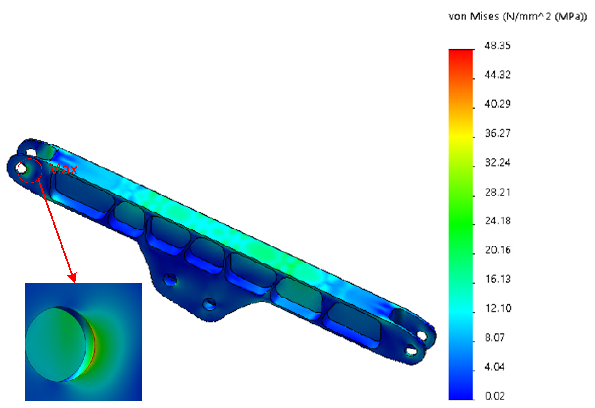
4.2. Results of the Static Analysis of the Robot Arm under Excavation Conditions

According to the dynamic simulation results of ADAMS under the digging condition of the arm, the working arm is adjusted to the attitude corresponding to the maximum force at the articulation point, and the pre-processing of the finite element analysis model of the working arm and the displacement boundary conditions are completed according to the static force analysis process under the handling condition in the previous section, and finally the X-axis and Y-axis load components corresponding to the maximum force at the articulation point are added to the corresponding articulated shaft holes in the form of bearing load with the local coordinate system as the reference coordinate system to complete the application of the load boundary conditions.
The parts of the base with large stress changes and stress maxima are shown in Figure 12. The maximum stress appears at the bolt hole; the stress maxima is 158.04 MPa, far less than the stress limit 505 MPa. According to the stress cloud diagram, it can be seen that the overall stress on the base is small, and it is only at the bolt hole that a larger stress appears. From the deformation cloud shown in Figure 13, it can be seen that the maximum deformation of the base is only 0.01 mm; the deformation is very small, which means that the base is relatively safe under stress.
The parts of the big arm with large stress changes and stress maxima are shown in Figure 14. The maximum stress appears at the open hole of the big arm, and the stress maxima is 103.85 MPa, which is much smaller than the stress limit of 505 MPa. According to the stress cloud diagram, it is seen that the big arm is under greater stress at the middle digging position. From the deformation cloud diagram shown in Figure 15, it can be seen that the deformation at the articulated shaft hole of the big arm and the cylinder barrel of the second arm is the largest, the maximum deformation is 0.24 mm, and the relative deformation is small.
The parts of the second arm where the stress changes more and the stress maximum are shown in Figure 16. The maximum stress appears at the articulation hole linked with the big arm. The stress maximum is 47.82 MPa, much less than the stress limit 505 MPa. According to the stress cloud diagram, the stress at the middle reinforcement of the second arm, the articulation hole, and the stress at the back is larger. The maximum position of deformation appears at the end of the second arm and the three arms’ articulated shaft hole ear plate, as shown in Figure 17. The maximum value of deformation is 0.96 mm, and close to the robot arm base direction, the deformation is relatively small.
The maximum stress of the third arm is 98.06 MPa, as shown in Figure 18, which is much less than the stress limit of 505 MPa. According to the stress cloud diagram in Figure 19, the middle reinforcement and the transition lug plate of the hinge hole of the three arms are under greater stress. The deformation cloud under excavation condition is shown in Figure 18, the maximum deformation is 3.27 mm at the end of the three arms and the swing-frame articulated shaft hole, and the remaining parts are relatively small.

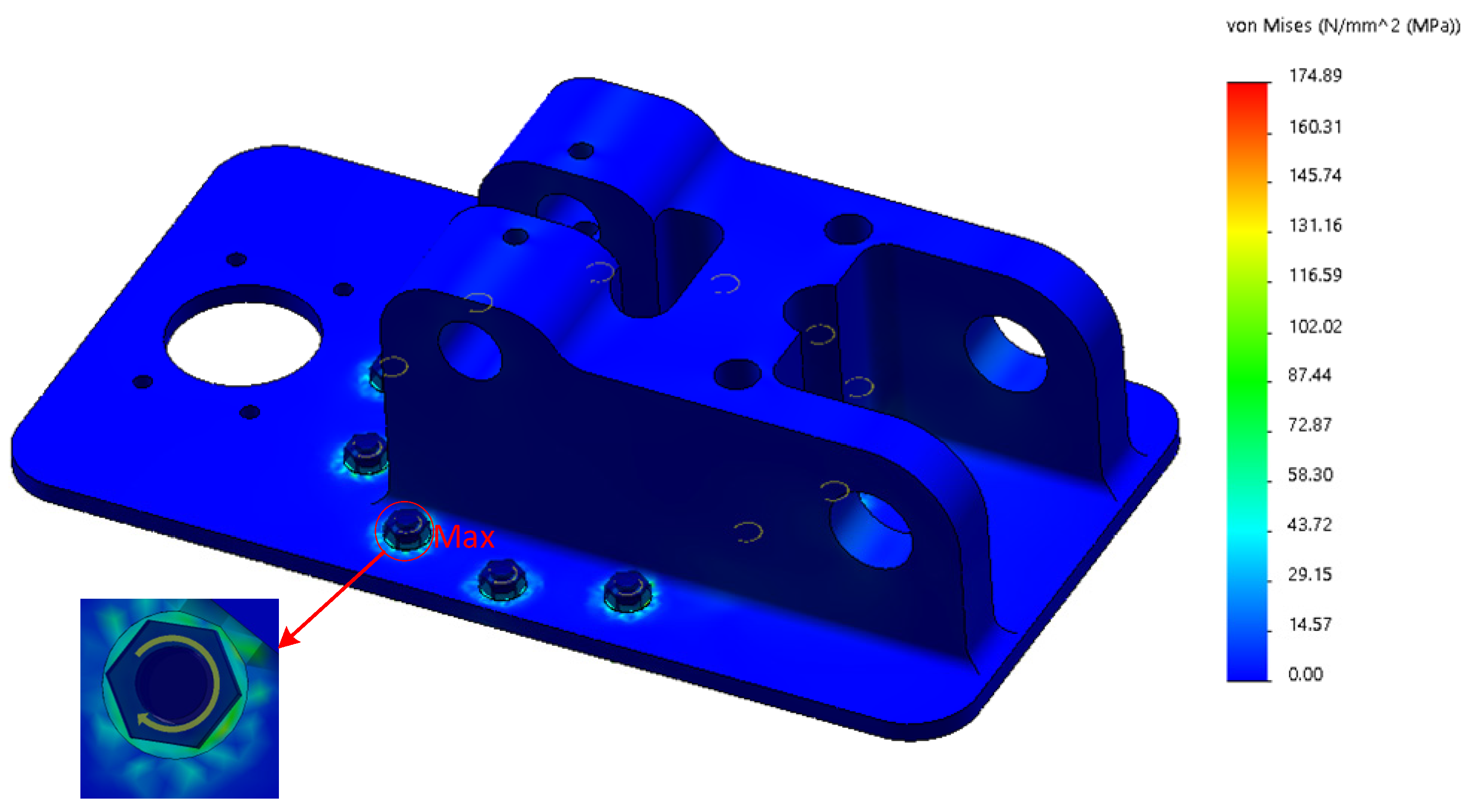
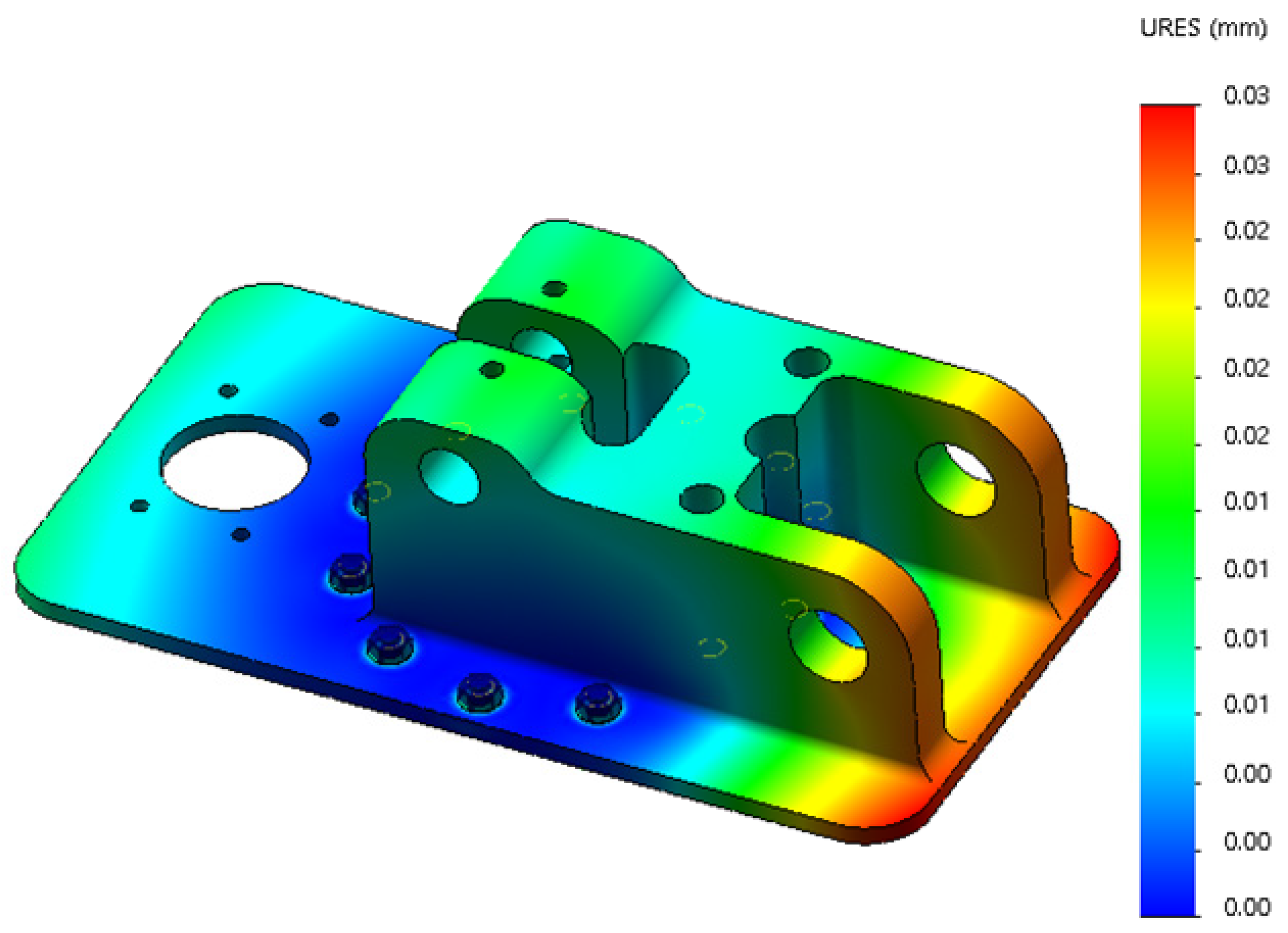
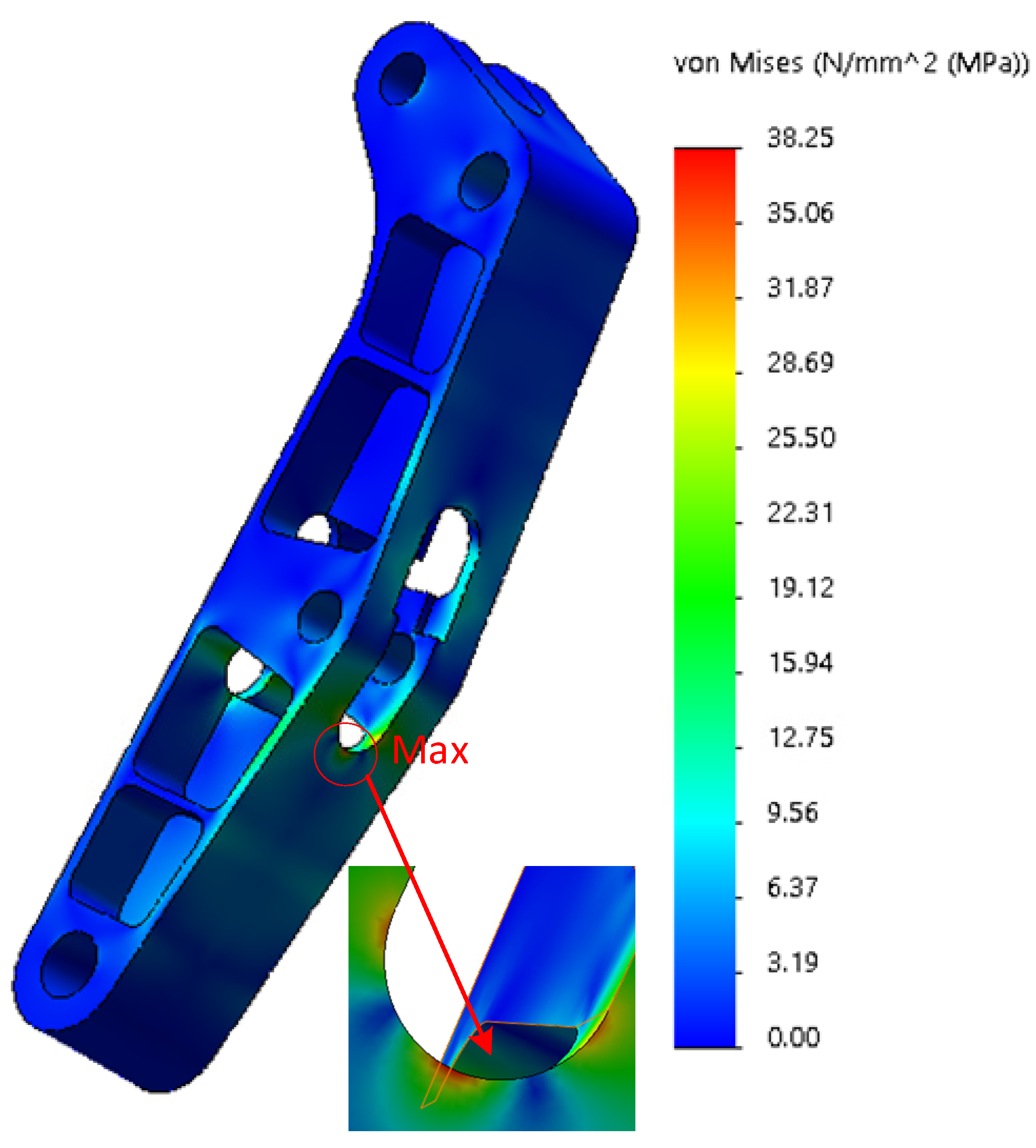
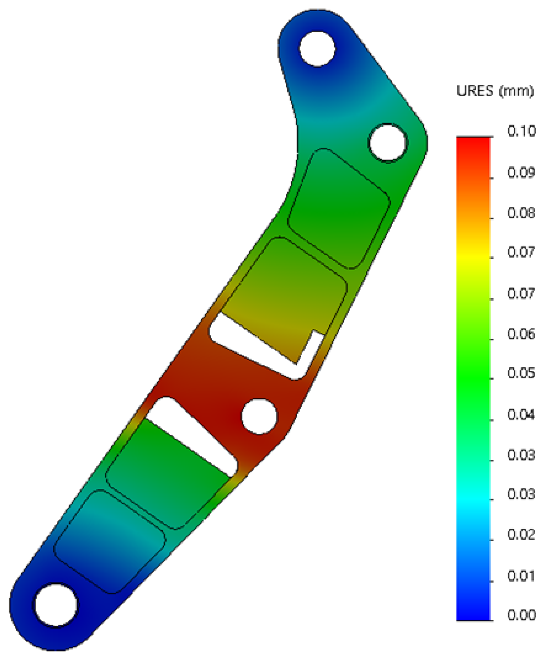
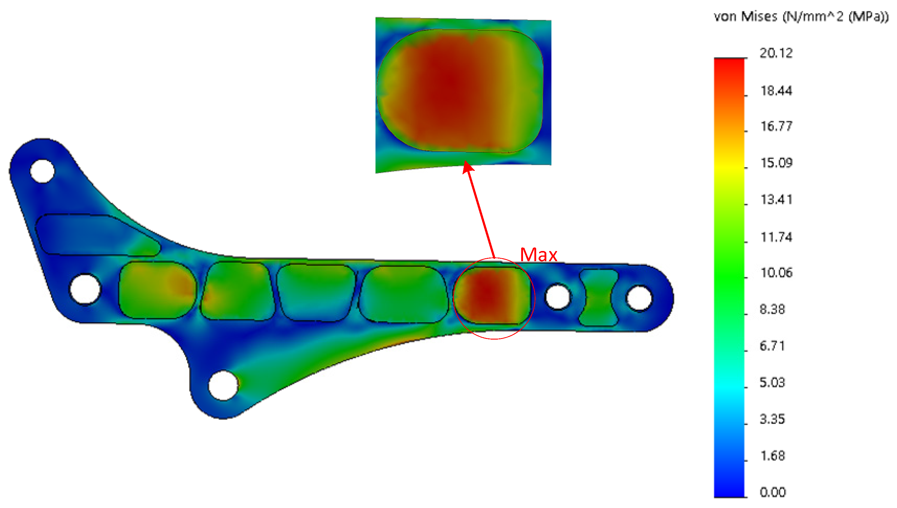
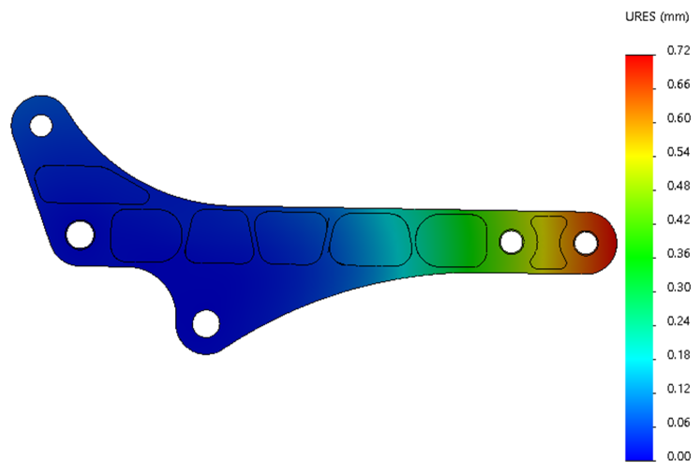
4.3. Results of the Static Analysis of the Robot Arm under Handling Conditions

According to the dynamic simulation results of ADAMS under the handling condition of the robot arm, the working arm is adjusted to the attitude corresponding to the maximum force at the articulation point, and the pre-processing and displacement boundary conditions of the finite element analysis model of each working arm are completed according to the static force analysis process under the handling condition in the previous section.
The parts of the base with large stress variation and stress maximum are shown in Figure 20. The maximum stress appears at the bolt hole, and the stress maximum is 174.89 MPa, which is much smaller than the stress limit of 505 MPa. From the deformation cloud shown in Figure 21, it can be seen that the maximum deformation of the base is only 0.03 mm; the deformation is very small, which means that the base is relatively safe under stress.
Big-arm stress changes and stress maximum parts as shown in Figure 22. The maximum stress appears in the open hole of the big arm, and the stress maximum value is 38.25 MPa, far less than the stress limit 505 MPa. According to the stress cloud diagram, the big arm in the middle of the digging position can be seen near the larger force. From the deformation cloud diagram shown in Figure 23, it can be seen that the maximum deformation occurs at the articulated shaft hole of the big arm and the cylinder barrel of the second arm, the maximum deformation is 0.01 mm, and the relative deformation is small.
The parts of the second arm where the stress changes more and the stress maximum are shown in Figure 24. The maximum stress appears at the articulated hole linked with the big arm; the stress maximum is 48.35 MPa, much less than the stress limit 505 MPa. According to the stress cloud diagram, at the middle reinforcement of the second arm and the articulated hole, the stress is larger. The maximum position of deformation appears at the end of the second arm and the three arms’ articulated shaft hole trunnion, as shown in Figure 25. The maximum value of deformation is 1.49 mm, and close to the direction of the base of the robot arm, the deformation is relatively small.
The maximum stress of the third arm is 20.12 MPa, as shown in Figure 26, which is much less than the stress limit of 505 MPa. According to the stress cloud diagram in Figure 26, the middle reinforcement bar and the transition lug plate of the hinge hole of the three arms are under greater stress. The deformation cloud under excavation condition is shown in Figure 27. The maximum deformation is 0.72 mm at the end of the three arms and the swing-frame articulated shaft hole. The remaining parts have a relatively small deformation.

5. Prototype and Analysis of Hydraulic Machinery Arm
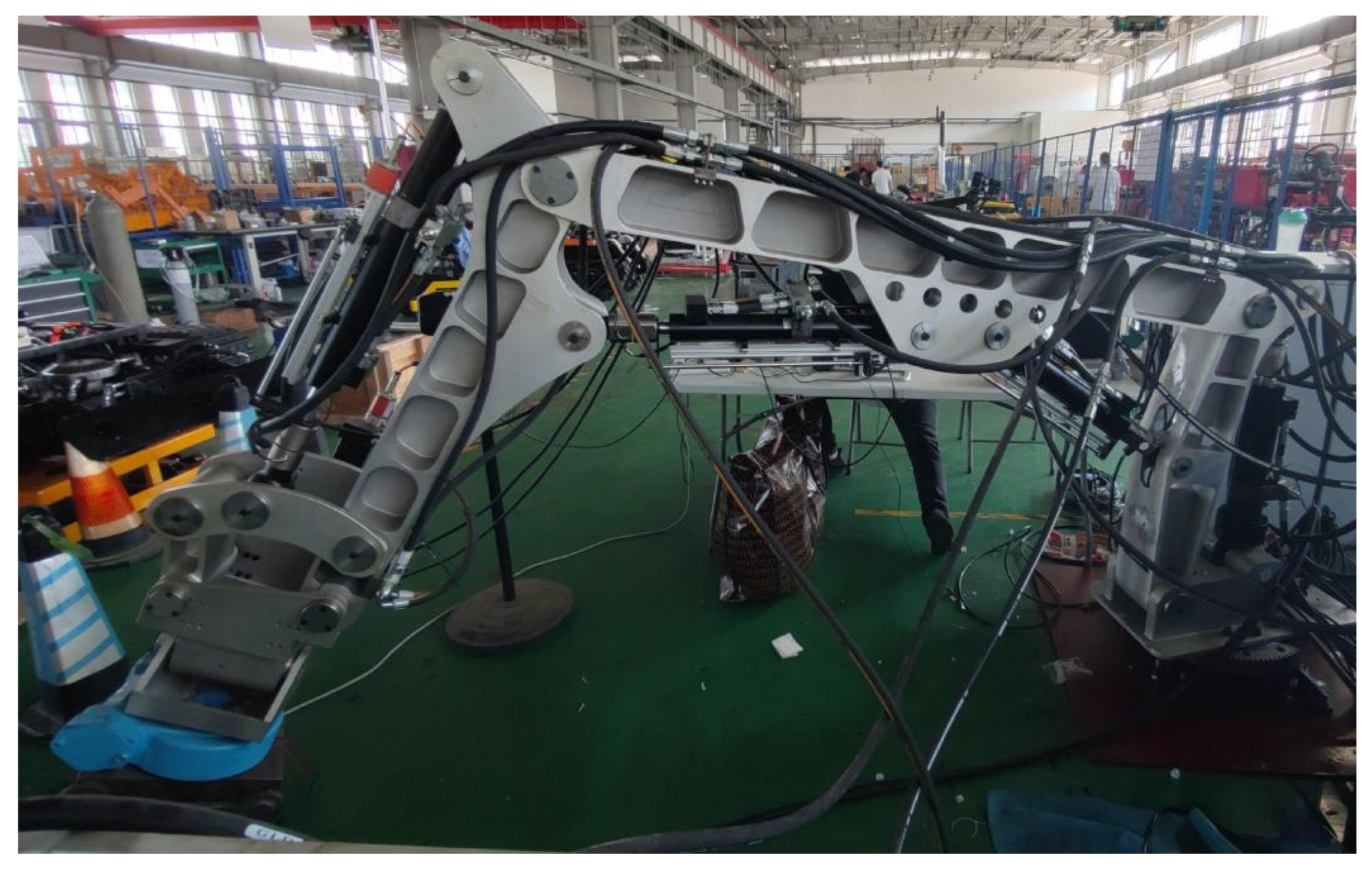
5.1. Prototype

It has been established through finite element analysis and dynamic simulation that the designed structure satisfies the necessary strength standards. Based on the planned robotic arm concept, a hydraulic robotic arm prototype is made and shown in Figure 28. The oil cylinder and hydraulic motor, which serve as the robotic arm’s drive units, both have displacement sensors, setting the groundwork for eventual displacement closed-loop control. The hydraulic flow rate of each of the robotic arm’s driving components is managed by a number of hydraulic proportional directional valves.

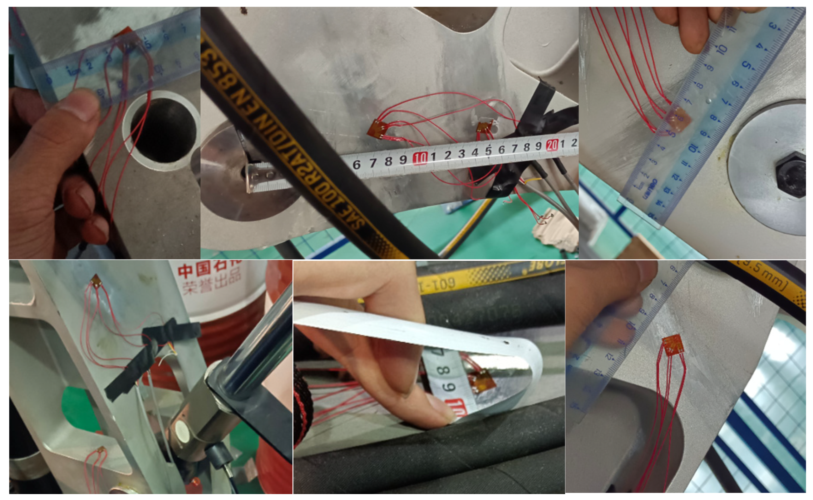
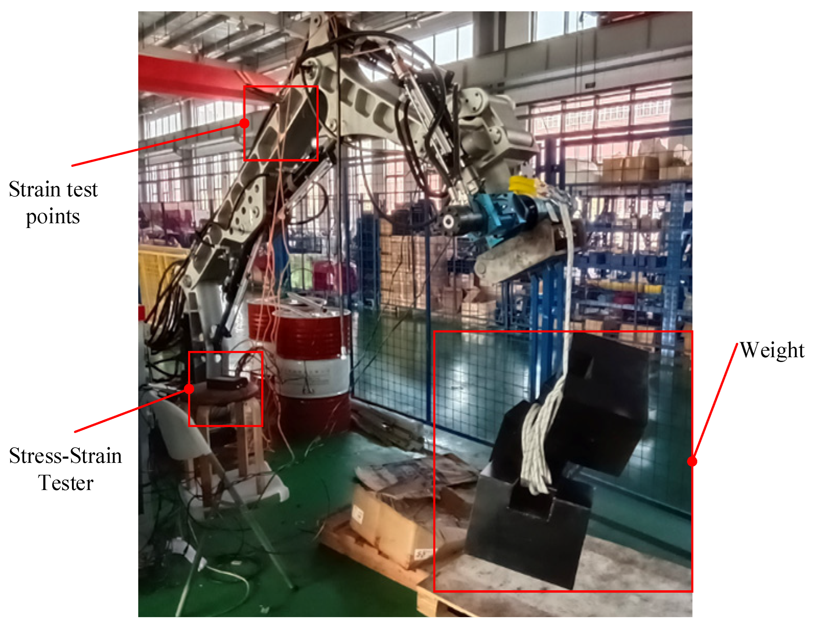
5.2. Finite Element Experiments

The finite element method is widely used in structural design optimization, but the structural model is simplified for the sake of calculation simplicity, there are some differences with the actual structure and process, and the boundary conditions are set differently from the actual one. Therefore, the correctness of the finite element model is tested by the test results and, the smaller the error, the closer it is to the actual one. In this section, based on the completed FEM analysis, the stress–strain test is conducted on the robot arm to verify the feasibility of the finite element model.

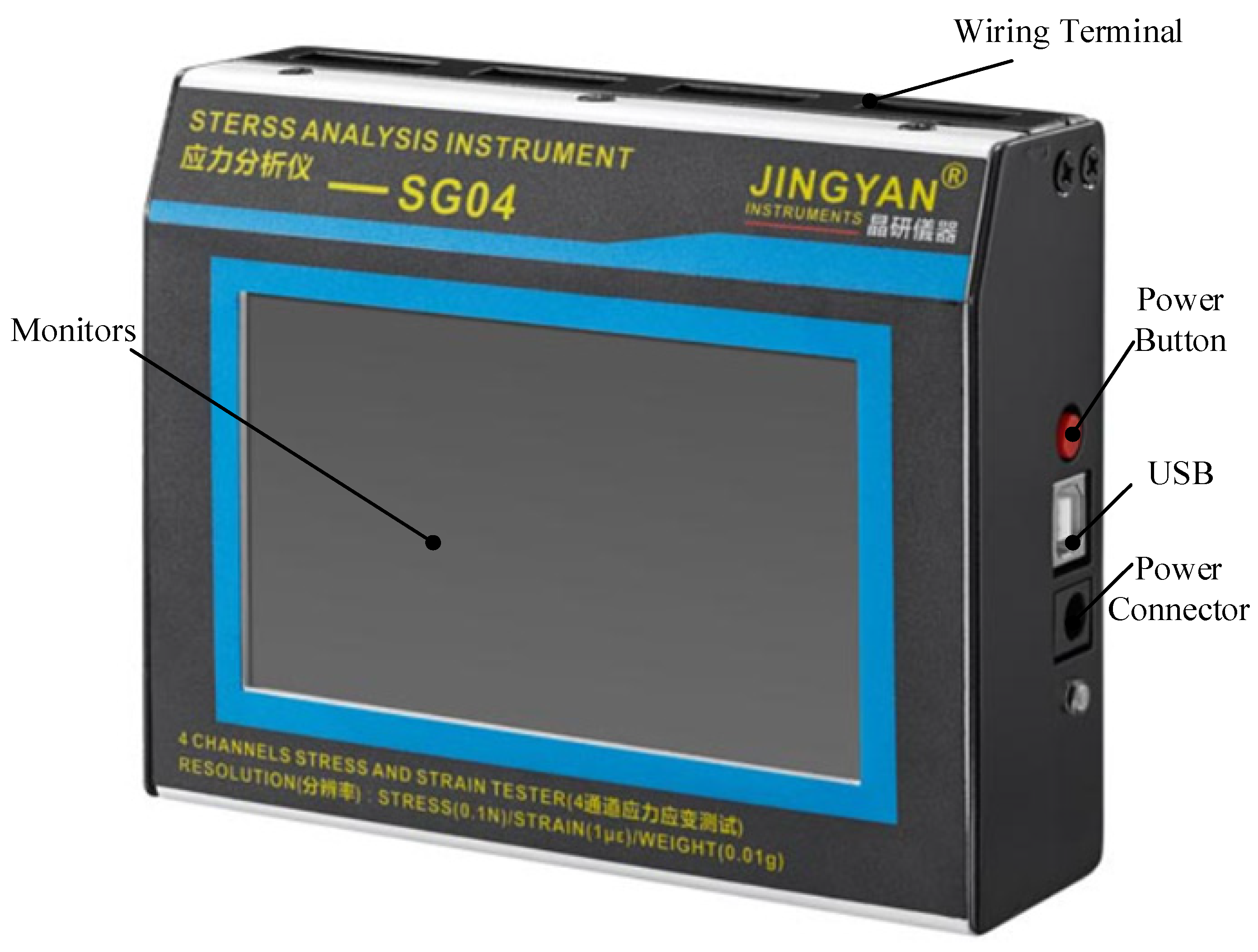
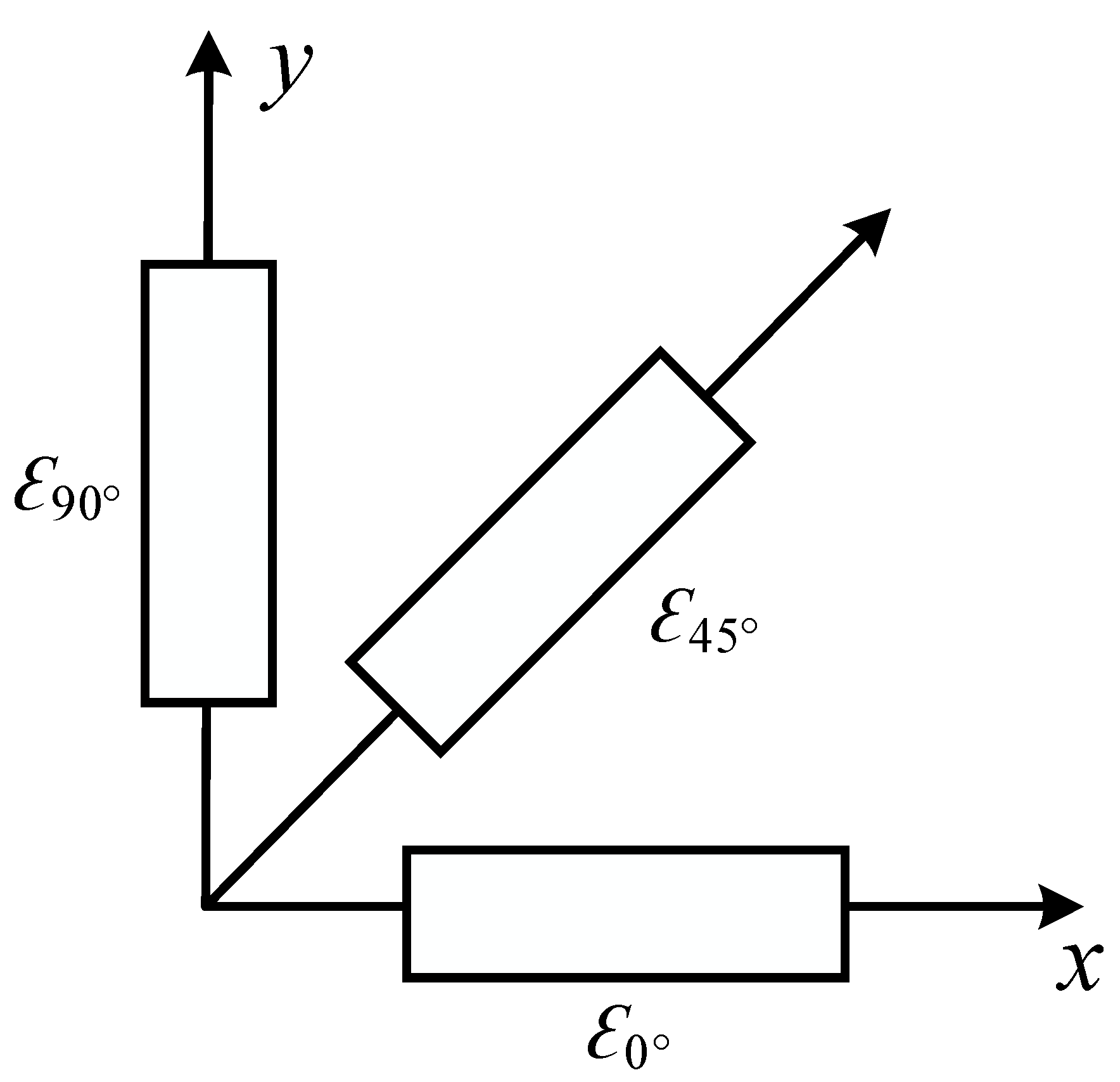
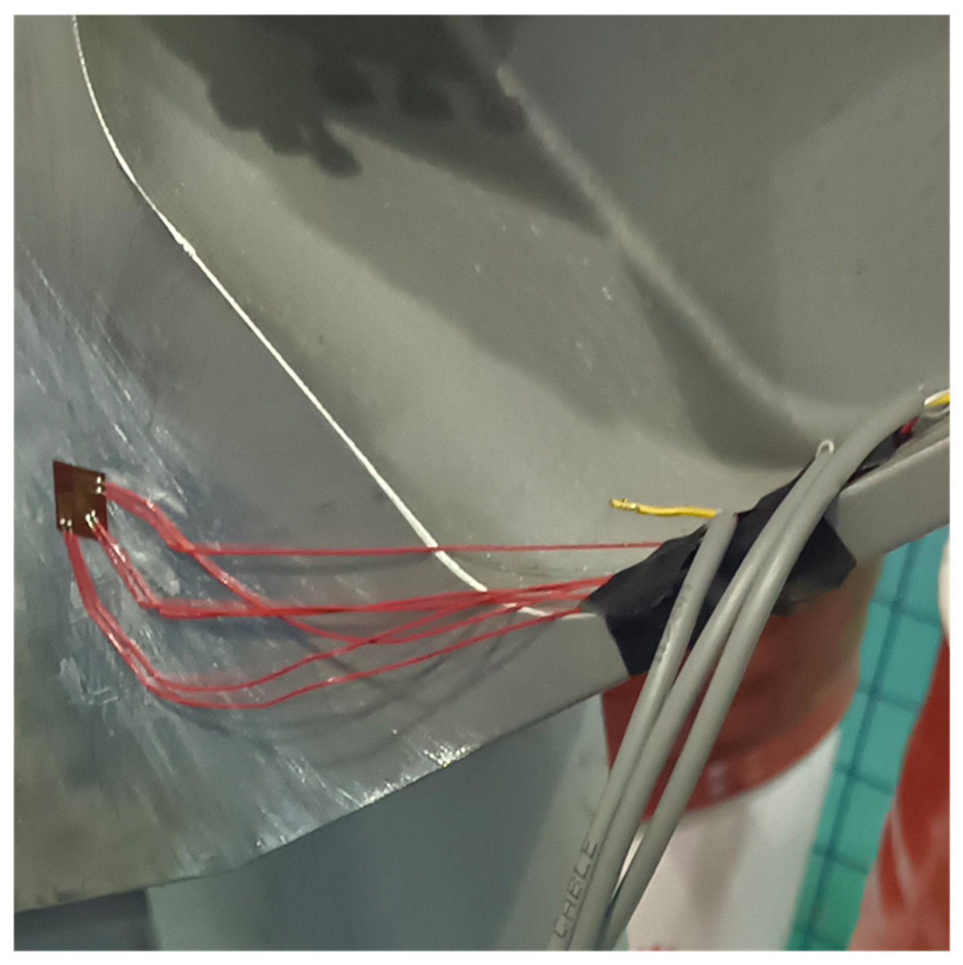
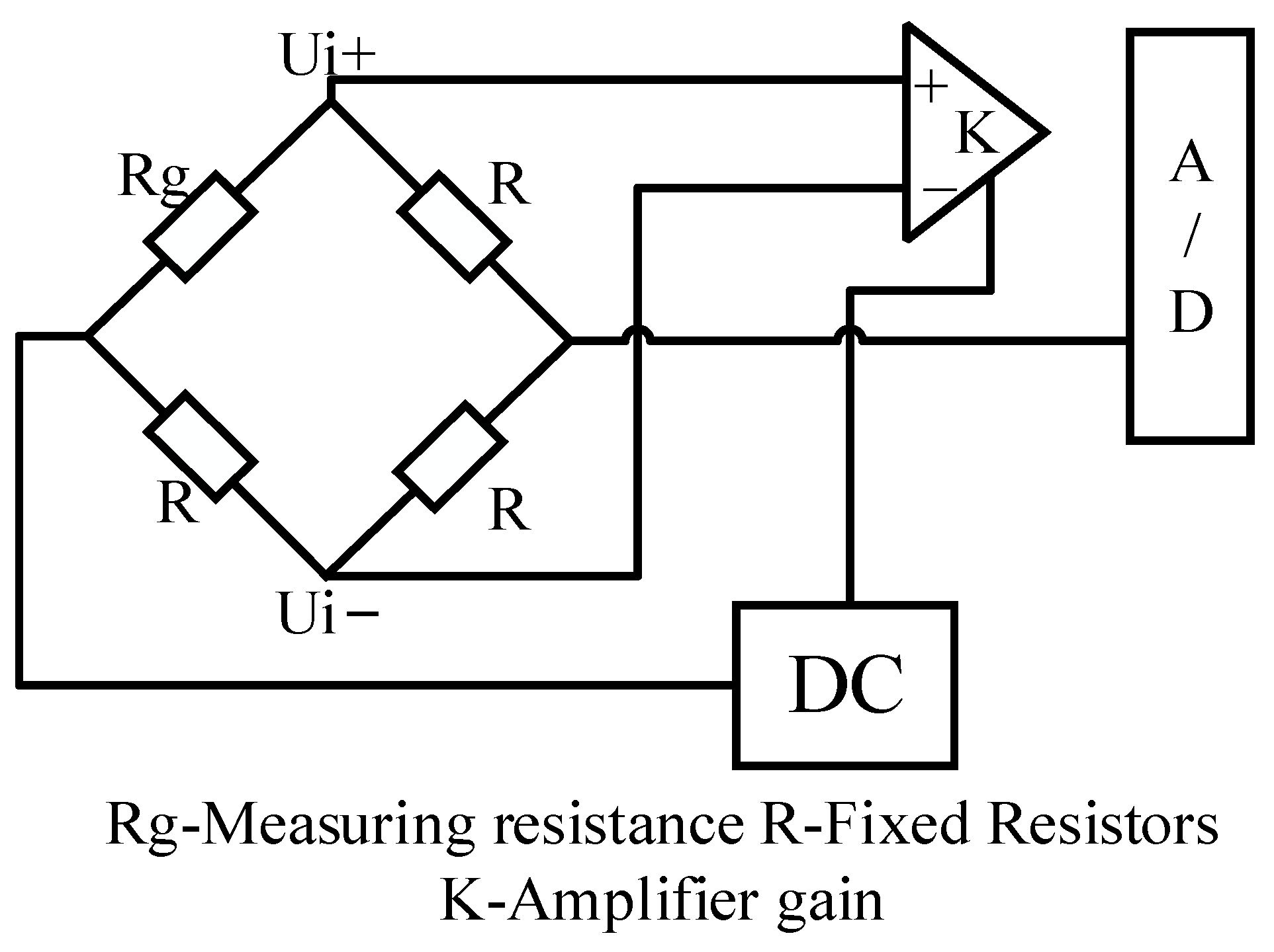
5.2.1. Preliminary Preparation of the Experiment

(1) Experimental equipment: JINGYAN Stress Tester: SG04 type, as shown in Figure 29 below.
The strain flower, with a resistance value 120Ω, sensitivity factor 2.0, Poisson’s ratio 0.27, resolution 0.1, three axes at 45° to each other, can be used to test the strain in the direction of unknown principal stress. The strain flower schematic diagram and installation are shown in Figure 30 and Figure 31.
(2) Measuring bridge design and principle: A simple and reliable 1/4 bridge was used for the bridges, where each strain flower needs to be connected to three bridges, and the measuring bridge principle is shown in Figure 32 below.
When the analyzer calculates the strain magnitude of the three bridge paths of the strain flower, the ultimate strain value of this experimental object can be found by the following equation:
ε x = ε 0 ° , ε y = ε 90 ° , γ x y = ε 0 ° + ε 90 ° 2 ε 45 °
σ x = E 1 μ 2 ε x + μ ε y
σ y = E 1 μ 2 ε y + μ ε x
τ x = E 2 1 + μ γ x y
where σx, σy, τx are the plane stresses; εx, εx, γxy are the corresponding strain values. This leads to:
σ max = σ x + σ y 2 + σ x σ y 2 2 + τ x 2
σ min = σ x + σ y 2 σ x σ y 2 2 + τ x 2
σ 1 = σ max , σ 2 = 0 , σ 3 = σ min
Then, the equivalent force value σs at this measurement location can be derived from the fourth strength theory as:
σ s = 1 2 σ 1 σ 2 2 + σ 1 σ 3 2 + σ 2 σ 3 2
(3) Cautions: In order to improve the accuracy of the experiment, the measurement locations should be polished before the patching, and, in addition, the stress concentrations appearing in the finite element analysis should be selected as much as possible when patching the strain gauges, such as axial holes and other easily damaged parts. The location of the patch point should be recorded. Some patch point locations are shown in Figure 33.
(4) Test Method: The weight hanging at the end of the robotic arm is 300 kg. The robotic arm is adjusted to a specific attitude, the individual cylinder extensions are recorded, apply strain gauges, and the channels are zeroed. The weight is weighed and gently suspended at the end of the robotic arm and, after the arm is balanced, the strain value at each test point is collected. The test arrangement is shown in Figure 34.
After the test is completed, the robot arm is adjusted to the corresponding attitude, the corresponding load is applied, the load distribution at each point is simulated, the load distribution data is exported and loaded onto the finite element model of the robot arm, multiple points are taken for the experimental patch position, and the average value of the simulated value at that point is obtained as the simulated value of that position. The position of all measurement points on the robot arm is shown in Figure 35.

5.2.2. Results and Analysis of the Experiment

The expansion and contraction of each hydraulic cylinder is shown in Table 5 below. The test point processing results are shown in Table 6. Referring to the above calculation and analysis process, we can see that the difference between the simulated value and the experimental measured stress value is not large, and the error between the experimental and simulated values may come from the model simplification and the error caused by the unevenness of the patch in the experiment. However, according to the above data, the simulation has good reference significance and can guarantee the structural and mechanical reliability of the robot arm, but still needs to leave enough safety margin in the design process, generally with a safety factor of 1.5–3 as a reference standard.

6. Discussion

Based on the aforementioned simulation and experimental findings, it is clear that the robotic arm used in this study, which was built using aluminum alloy 7075, has the advantages of low weight and high load. The mechanism of the research robotic arm is not, however, the best-designed structure. To further lower the weight of the robotic arm, topology optimization of the structure might be carried out. Stress–strain tests were performed to determine the robotic arm’s strength, and the results show that while the finite element results are quite descriptive, the relative errors for points 1, 2, 6, 8, and 13 are relatively large. This suggests that the accuracy of the testing apparatus and the testing procedure can be further optimized.

7. Conclusions

In this paper, we started from the structural design of the seven-degree-of-freedom redundant rescue hydraulic robotic arm, completed the 3D model assembly in Solidworks, and then completed the finite element static analysis and structural optimization design of the robotic arm according to the actual working conditions of the rescue robotic arm, which is lightweight and has a high load and large working range. In ADAMS simulation software, a virtual prototype of the mechanical analysis of the rescue hydraulic robotic arm was built to simulate the two common working conditions of excavation and handling, and to analyze the force of the robotic arm, followed by finite element analysis of the key parts of the robotic arm. In order to verify the accuracy of the finite element static analysis method of the robotic arm in this paper, theoretical and practical research methods were used, and stress–strain experiments were conducted at important locations of the robotic arm according to the finite element analysis model, verifying the correctness of the finite element analysis method. In future research, different advanced control strategies will be applied to the robotic arm to further validate its capacity.

Author Contributions

Conceptualization, J.Z. and W.J.; methodology, W.J.; software, W.J. and Q.Z.; validation, W.J., Q.Z. and W.Z.; formal analysis, W.J. and Q.Z.; investigation, W.J.; resources, J.Z.; data curation, W.J. and W.Z.; writing—original draft preparation, W.J.; writing—review and editing, J.Z.; supervision, J.Z.; project administration, J.Z.; funding acquisition, J.Z. All authors have read and agreed to the published version of the manuscript.

Funding

This work is supported by National Natural Science Foundation of China (52275285).

Data Availability Statement

Data will be made available on request.

Conflicts of Interest

The authors declare no conflict of interest.

Abbreviations

SCARA—Selective Compliance Assembly Robot Arm; NSGA-II—Non-dominated sorting genetic algorithm II; 7-DOFs—seven degrees of freedom; FEM—Finite Element Method.

References

  1. Takahashi, T.; Tadakuma, K.; Watanabe, M.; Takane, E.; Hookabe, N.; Kajiahara, H.; Yamasaki, T.; Konyo, M.; Tadokoro, S. Eversion Robotic Mechanism With Hydraulic Skeletonto Realize Steering Function. IEEE Robot. Autom. Lett. 2021, 6, 5413–5420. [Google Scholar] [CrossRef]
  2. Han, S.; Chon, S.; Kim, J.; Seo, J.; Shin, D.G.; Park, S.; Kim, J.T.; Kim, J.; Jin, M.; Cho, J. Snake Robot Gripper Module for Search and Rescue in Narrow Spaces. IEEE Robot. Autom. Lett. 2022, 7, 1667–1673. [Google Scholar] [CrossRef]
  3. Hagiwara, T.; Katou, Y. Trial Production of a Small Snake Type Robot That Can Be Mounted on a Disaster Rescue Robot. In Proceedings of the 2021 18th International Conference on Electrical Engineering/Electronics, Computer, Telecommunications and Information Technology (ECTI-CON), Chiang Mai, Thailand, 19–22 May 2021; pp. 1104–1107. [Google Scholar]
  4. Yuan, J.; Wang, Z.; Zhang, Z.; Xing, Y.; Ji, A. Mechanism Design of a Transformable Crawling Robot and Feasibility Analysis for the Unstructured Environment. Actuators 2022, 11, 60. [Google Scholar] [CrossRef]
  5. Voyles, R.M.; Larson, A.C. TerminatorBot: A Novel Robot With Dual-Use Mechanism for Locomotion and Manipulation. IEEE/ASME Trans. Mechatron. 2005, 10, 17–25. [Google Scholar] [CrossRef]
  6. Cruz Ulloa, C.; Domínguez, D.; Del Cerro, J.; Barrientos, A. A Mixed-Reality Tele-Operation Method for High-Level Control of a Legged-Manipulator Robot. Sensors 2022, 22, 8146. [Google Scholar] [CrossRef]
  7. Bai, L.; Li, X.; Sun, Y.; Zheng, J.; Chen, X. A Wheel-Legged Mobile Robot with Adjustable Body Length for Rescue and Search. In Proceedings of the 2021 6th IEEE International Conference on Advanced Robotics and Mechatronics (ICARM), Chongqing, China, 3–5 July 2021; pp. 340–345. [Google Scholar]
  8. Wang, R.; Chen, Z.; Xu, K.; Wang, S.; Wang, J.; Li, B. Hybrid Obstacle-Surmounting Gait for Hexapod Wheel-Legged Robot in Special Terrain. In Proceedings of the 2021 6th IEEE International Conference on Advanced Robotics and Mechatronics (ICARM), Chongqing, China, 3–5 July 2021; pp. 1–6. [Google Scholar]
  9. Lee, D.-H.; Huynh, T.; Kim, Y.-B.; Soumayya, C. Motion Control System Design for a Flying-Type Firefighting System with Water Jet Actuators. Actuators 2021, 10, 275. [Google Scholar] [CrossRef]
  10. Liu, H.; Ge, J.; Wang, Y.; Li, J.; Ding, K.; Zhang, Z.; Guo, Z.; Li, W.; Lan, J. Multi-UAV Optimal Mission Assignment and Path Planning for Disaster Rescue Using Adaptive Genetic Algorithm and Improved Artificial Bee Colony Method. Actuators 2021, 11, 4. [Google Scholar] [CrossRef]
  11. Focchi, M.; Bensaadallah, M.; Frego, M.; Peer, A.; Fontanelli, D.; Del Prete, A.; Palopoli, L. CLIO: A Novel Robotic Solution for Exploration and Rescue Missions in Hostile Mountain Environments. In Proceedings of the 2023 IEEE International Conference on Robotics and Automation (ICRA), London, UK, 29 May–2 June 2023; pp. 7742–7748. [Google Scholar]
  12. Ye, C.; Su, Y.; Yu, S.; Wang, Y. Development of a Deformable Water-Mobile Robot. Actuators 2023, 12, 202. [Google Scholar] [CrossRef]
  13. Yuguchi, Y.; Satoh, Y. Development of a Robotic System for Nuclear Facility Emergency Preparedness—Observing and Work-Assisting Robot System. Adv. Robot. 2002, 16, 481–484. [Google Scholar] [CrossRef]
  14. Nishida, T.; Koga, H.; Fuchikawa, Y.; Kitayama, Y.; Kurogil, S.; Arimura, Y. Development of Pilot Assistance System with Stereo Vision for Robot Manipulation. In Proceedings of the 2006 SICE-ICASE International Joint Conference, Busan, Republic of Korea, 18–21 October 2006. [Google Scholar]
  15. Wolf, A.; Brown, H.B.; Casciola, R.; Costa, A.; Schwerin, M.; Shamas, E.; Choset, H. A Mobile Hyper Redundant Mechanism for Search and Rescue Tasks. In Proceedings of the 2003 IEEE/RSJ International Conference on Intelligent Robots and Systems (IROS 2003) (Cat. No.03CH37453), Las Vegas, NV, USA, 27–31 October 2003; Volume 3, pp. 2889–2895. [Google Scholar]
  16. Liang, X.; Wan, Y.; Zhang, C.; Kou, Y.; Xin, Q.; Yi, W. Robust Position Control of Hydraulic Manipulators Using Time Delay Estimation and Nonsingular Fast Terminal Sliding Mode. Proc. Inst. Mech. Eng. Part I J. Syst. Control Eng. 2018, 232, 50–61. [Google Scholar] [CrossRef]
  17. Zhou, L.; Bai, S. A New Approach to Design of a Lightweight Anthropomorphic Arm for Service Applications. J. Mech. Robot. 2015, 7, 031001. [Google Scholar] [CrossRef]
  18. Li, Z.; Milutinović, D.; Rosen, J. Design of a Multi-Arm Surgical Robotic System for Dexterous Manipulation. J. Mech. Robot. 2016, 8, 061017. [Google Scholar] [CrossRef]
  19. Dämmer, G.; Gablenz, S.; Neumann, R.; Major, Z. Design, Topology Optimization, and Additive Manufacturing of a Pneumatically Actuated Lightweight Robot. Actuators 2023, 12, 266. [Google Scholar] [CrossRef]
  20. Wu, Z.; Jiang, T. Property Analysis and Structure Optimization of Robotic Arm Based on Pro/E and ANSYS. J. Chang. Univ. Sci. Technol. (Nat. Sci. Ed.) 2011, 34, 3. [Google Scholar] [CrossRef]
  21. Li, K.; Huo, Y.; Liu, Y.; Shi, Y.; He, Z.; Cui, Y. Design of a Lightweight Robotic Arm for Kiwifruit Pollination. Comput. Electron. Agric. 2022, 198, 107114. [Google Scholar] [CrossRef]
  22. Evans, A.G. Lightweight Materials and Structures. MRS Bull. 2001, 26, 790–797. [Google Scholar] [CrossRef]
  23. Yeo, S.J.; Oh, M.J.; Yoo, P.J. Structurally Controlled Cellular Architectures for High-Performance Ultra-Lightweight Materials. Adv. Mater. 2019, 31, 1803670. [Google Scholar] [CrossRef]
  24. Sun, Q.; Zhou, G.; Meng, Z.; Jain, M.; Su, X. An Integrated Computational Materials Engineering Framework to Analyze the Failure Behaviors of Carbon Fiber Reinforced Polymer Composites for Lightweight Vehicle Applications. Compos. Sci. Technol. 2021, 202, 108560. [Google Scholar] [CrossRef]
  25. Tam, K.-M.M.; Marshall, D.J.; Gu, M.; Kim, J.; Huang, Y.; Lavallee, J.; Mueller, C.T. Fabrication-Aware Structural Optimisation of Lattice Additive-Manufactured with Robot-Arm. Int. J. Rapid Manuf. 2018, 7, 120–168. [Google Scholar] [CrossRef]
  26. Salvati, E.; Korsunsky, A.M. Micro-Scale Measurement & FEM Modelling of Residual Stresses in AA6082-T6 Al Alloy Generated by Wire EDM Cutting. J. Mater. Process. Technol. 2020, 275, 116373. [Google Scholar] [CrossRef]
  27. Yanhui, Y.; Dong, L.; Ziyan, H.; Zijian, L. Optimization of Preform Shapes by RSM and FEM to Improve Deformation Homogeneity in Aerospace Forgings. Chin. J. Aeronaut. 2010, 23, 260–267. [Google Scholar] [CrossRef]
  28. Liu, J.; Ma, Y. A Survey of Manufacturing Oriented Topology Optimization Methods. Adv. Eng. Softw. 2016, 100, 161–175. [Google Scholar] [CrossRef]
  29. Mantovani, S.; Presti, I.L.; Cavazzoni, L.; Baldini, A. Influence of Manufacturing Constraints on the Topology Optimization of an Automotive Dashboard. Procedia Manuf. 2017, 11, 1700–1708. [Google Scholar] [CrossRef]
  30. Zuo, K.-T.; Chen, L.-P.; Zhang, Y.-Q.; Yang, J. Manufacturing- and Machining-Based Topology Optimization. Int. J. Adv. Manuf. Technol. 2006, 27, 531–536. [Google Scholar] [CrossRef]
  31. Rout, B.K.; Mittal, R.K. Optimal Design of Manipulator Parameter Using Evolutionary Optimization Techniques. Robotica 2010, 28, 381–395. [Google Scholar] [CrossRef]
  32. Liu, W.; Zhu, H.; Wang, Y.; Zhou, S.; Bai, Y.; Zhao, C. Topology Optimization of Support Structure of Telescope Skin Based on Bit-Matrix Representation NSGA-II. Chin. J. Aeronaut. 2013, 26, 1422–1429. [Google Scholar] [CrossRef]
Figure 1. Mechanical arm structure schematic.
Actuators 12 00362 g001
Figure 2. Models of the main parts of the robot arm: (a) Structural diagram of base; (b) Structural diagram of the first arm; (c) Structural diagram of the second arm; (d) Structural diagram of the third arm; (e) Structural diagram of the wrist joint.
Actuators 12 00362 g002
Figure 3. Dangerous posture of the robot arm under digging conditions. (a) Maximum depth attitude, (b) Maximum bending moment attitude, (c) Tooth tip and working arm co-linear attitude.
Actuators 12 00362 g003
Figure 4. Bucket movement trajectory under digging conditions of the robot arm.
Actuators 12 00362 g004
Figure 5. Digging resistance change curve.
Actuators 12 00362 g005
Figure 6. Diagram of the articulation point of each working arm of the rescue robot arm.
Actuators 12 00362 g006
Figure 7. Force diagram of arm joint articulation point under digging conditions: (a) Force at the articulation point of the base; (b) Force at the articulation point of the first arm; (c) Force at the articulation point of the second arm; (d) Force at the articulation point of the third arm.
Actuators 12 00362 g007
Figure 8. Robotic arm trajectory under handling conditions.
Actuators 12 00362 g008
Figure 9. Force diagram of joint articulation point of robot arm under handling conditions: (a) Force at the articulation point of the base; (b) Force at the articulation point of the first arm; (c) Force at the articulation point of the second arm; (d) Force at the articulation point of the third arm.
Actuators 12 00362 g009
Figure 10. Results of grid independence analysis.
Actuators 12 00362 g010
Figure 11. Schematic diagram of components meshing: (a) Schematic diagram of the third arm meshing; (b) Schematic diagram of the second arm meshing; (c) Schematic diagram of the first arm meshing; (d) Schematic diagram of base meshing.
Actuators 12 00362 g011
Figure 12. Stress cloud of base under excavation conditions.
Actuators 12 00362 g012
Figure 13. Strain cloud of base under excavation conditions.
Actuators 12 00362 g013
Figure 14. Stress cloud of first arm under excavation conditions.
Actuators 12 00362 g014
Figure 15. Strain cloud of first arm under excavation conditions.
Actuators 12 00362 g015
Figure 16. Stress cloud of second arm under excavation conditions.
Actuators 12 00362 g016
Figure 17. Strain cloud of second arm under excavation conditions.
Actuators 12 00362 g017
Figure 18. Stress cloud of third arm under excavation conditions.
Actuators 12 00362 g018
Figure 19. Strain cloud of third arm under excavation conditions.
Actuators 12 00362 g019
Figure 20. Stress cloud of base under handling conditions.
Actuators 12 00362 g020
Figure 21. Strain cloud of base under handling conditions.
Actuators 12 00362 g021
Figure 22. Stress cloud of first arm under handling conditions.
Actuators 12 00362 g022
Figure 23. Strain cloud of first arm under handling conditions.
Actuators 12 00362 g023
Figure 24. Stress cloud of second arm under handling conditions.
Actuators 12 00362 g024
Figure 25. Strain cloud of second arm under handling conditions.
Actuators 12 00362 g025
Figure 26. Stress cloud of third arm under handling conditions.
Actuators 12 00362 g026
Figure 27. Strain cloud of third arm under handling conditions.
Actuators 12 00362 g027
Figure 28. 7-DOFs rescue hydraulic robotic arm prototype.
Actuators 12 00362 g028
Figure 29. Jingyan SG04 stress tester.
Actuators 12 00362 g029
Figure 30. Strain flower schematic.
Actuators 12 00362 g030
Figure 31. Strain relief flower installation diagram.
Actuators 12 00362 g031
Figure 32. Schematic diagram of measuring bridge.
Actuators 12 00362 g032
Figure 33. Strain gauge patch diagram.
Actuators 12 00362 g033
Figure 34. Schematic diagram of mechanical arm stress–strain test site layout.
Actuators 12 00362 g034
Figure 35. Schematic diagram of measurement point location.
Actuators 12 00362 g035
Table 1. Mechanical arm design parameters table.
Performance IndicatorsParameters
Number of degrees of freedom7
Weight500 kg
Working radius4 m
Maximum load capacity300 kg
Power typeHydraulic
Table 2. The displacement drive function of each hydraulic cylinder of the robot arm under digging conditions.
DriversMotion Functions
The first arm hydraulic cylinder driver STEP ( TIME , 0 , 0 , 2.7 , 270 ) + STEP ( TIME , 16.6 , 0 , 19 , 270 )
The second arm hydraulic cylinder driver 0
The third arm hydraulic cylinder driver STEP ( TIME , 2.7 , 0 , 6.6 , 390 ) + STEP ( TIME , 12.6 , 0 , 16 . 6 , 390 )
Rotary hammer hydraulic cylinder driver STEP ( TIME , 6.6 , 0 , 12.6 , 295 ) + STEP ( TIME , 19 , 0 , 22 , 295 )
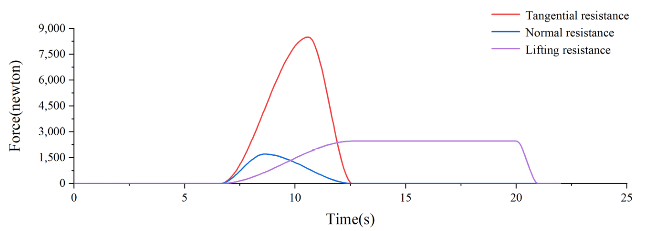
Tangential resistance STEP ( TIME , 6.6 , 0 , 10.6 , 8500 ) + STEP ( TIME , 10.6 , 0 , 12 . 6 , 8500 )
Normal resistance STEP ( TIME , 6.6 , 0 , 8.6 , 1700 ) + STEP ( TIME , 8.6 , 0 , 12.6 , 1700 )
Lifting resistance STEP ( TIME , 6.6 , 0 , 12.6 , 2460 ) + STEP ( TIME , 20 , 0 , 21 , 2460 )
Table 3. The displacement drive function of each hydraulic cylinder of the robot arm under handling conditions.
DriversMotion Functions
The first arm hydraulic cylinder driver STEP ( TIME , 49 , 0 , 59 , 270 ) + STEP ( TIME , 108 , 0 , 118 , 270 )
The second arm hydraulic cylinder driver STEP ( TIME , 0 , 0 , 10 , 378 ) + STEP ( TIME , 82 , 0 , 92 , 378 )
The third arm hydraulic cylinder driver STEP ( TIME , 10 , 0 , 26 , 390 ) + STEP ( TIME , 92 , 0 , 108 , 390 )
Rotary hammer hydraulic cylinder driver STEP ( TIME , 26 , 0 , 49 , 295 ) + STEP ( TIME , 59 , 0 , 82 , 295 )
Table 4. Grid parameters.
ComponentNumber of NodesNumber of CellsAspect Ratio < 3 (%)Flexure Unit (%)
Base415,702275,82999.40
The first arm453,166296,14999.50
The second arm1,248,279827,04299.20
The third arm774,436510,79799.10
Table 5. Telescopic length table of the hydraulic cylinder.
The First Arm Cylinder (mm)The Second Arm
Cylinder (mm)
The Third Arm
Cylinder (mm)
Rotary Hammer
Cylinder (mm)
2033560142
Table 6. Data processing results of stress and strain test points of prototypes.
Measurement PointsExperimental Value
(MPa)
Simulation Value (MPa)Absolute Error
(MPa)
10.4610.1500.311
21.3150.3220.993
32.3573.8921.535
45.3333.2752.058
53.3092.9450.364
64.2111.6042.607
71.3170.8520.465
81.2220.4980.724
99.55811.6232.065
101.5711.9640.393
117.0879.4322.345
125.1257.7332.608
131.0482.8531.805
142.1292.3070.178
153.5273.0610.466
163.5492.4041.124
171.9941.5590.435
Disclaimer/Publisher’s Note: The statements, opinions and data contained in all publications are solely those of the individual author(s) and contributor(s) and not of MDPI and/or the editor(s). MDPI and/or the editor(s) disclaim responsibility for any injury to people or property resulting from any ideas, methods, instructions or products referred to in the content.

