1. Introduction
The pursuit of high-performance compliant actuators is crucial for ensuring both the safety and effectiveness of collaborative robots [
1]. However, achieving a balance between safe operation, high performance (i.e., torque, speed, repeatability), and affordability remains a challenge in the field of compliant actuation, since there is a significant difference in the performance and cost of compliant actuators depending on the technology they are built on. This paper aims to address this challenge by investigating a unique property of MR (magneto-rheological) actuators— their inherent output boundedness. Unlike conventional actuation methods, MR actuators possess a unique ability to limit their output speed and/or torque, irrespective of the input torque and control commands across the entire control bandwidth. This inherent boundedness, in conjunction with other advantageous characteristics such as precise torque control, broad bandwidth, and compliance [
2], positions MR actuators as potential solutions to bridge the existing research gap in compliant actuator design. By studying this phenomenon in MR actuators, this study aims to achieve safe operation with high performance while maintaining cost effectiveness [
3].
To better understand this gap, it is important to note two contrasting approaches in the design of compliant actuators. One common approach involves mimicking compliance behavior by controlling high-end actuators such as harmonic drive actuators solely based on sensor readings. Examples of robots using this approach include Franka, UR5/10/15, JACO, KUKA iiwa, and ABB YuMi [
4,
5,
6,
7,
8]. These robots are designed with relatively small payloads and lightweight structures to ensure safe operation. These robots are more expensive to produce due to specific actuators and the sensors they require. However, in recent years, there has been a large decrease in prices as collaborative robot development has gained momentum.
On the other end of the design spectrum are low-cost compliant actuators, primarily realized with series elastics or variable impedance components. Examples of robots using such actuators are Sawyer/Swayer Black Edition, its predecessor Baxter (now obsolete), and Spot Arm [
9,
10]. Although these robots are compliant, they have poor repeatability and cannot perform high-precision tasks. There have been some attempts at recuperating the actuation performance at the expense of increased design complexity, blurring the distinction between different types of collaborative robots.
Regardless of their actuation technology, all existing collaborative robots have limited torque capacity to ensure their safety, highlighting the existing technology gap. To the best of our knowledge, there is currently no compliant actuator that can simultaneously deliver very high torque while meeting the requirements of safe actuation and inherent compliance.
With this specific gap in mind, we previously developed a new compliant actuation paradigm using MR clutches. In this paradigm, each rotational axis of motion is driven by a pair of antagonistic MR clutches—one providing clockwise (CW) motion or torque and the other providing counterclockwise (CCW) motion or torque. All pairs of MR clutches are connected to a common active source, such as an electric motor. The actuation paradigm is depicted schematically in
Figure 1.
This actuation paradigm inherits all properties of MR clutches, including precise torque control, broad bandwidth, and inherent compliance [
2,
11]. This study extends these properties to include the inherent boundedness of the MR actuator output, highlighting its safe operation. Although an MR clutch is a passive device, one cannot claim such property is preserved in an MR actuator (i.e., a combination of an active source and MR clutches). We analytically study this problem, present theoretical proof, and experimentally show that this passive behavior is preserved in MR actuators, regardless of the closed-loop control commands and/or mechanical input to the MR clutches. It is shown that an MR actuator slows down the actuation speed as soon as its output speed exceeds a predetermined value. This behavior is not a response to any speed measurements and/or control actions, but rather an inherent behavior of the actuator. This behavior also extends to multi-axis actuation.
The inherent boundedness of the output of MR actuators, coupled with their low inertia, wide control bandwidth, precise torque control, and manufacturing simplicity, makes MR actuators a suitable solution for achieving safe, high-performance, and cost-effective actuation. Previous studies have focused on mechanical design [
12] and/or characterization of MR fluids in MR clutches. This work, however, concentrates on the control of MR actuators and represents the first study on the dynamic behavior of antagonistic MR actuators concerning the boundedness of their output. The findings of this study can serve as a basis for designing specific control strategies that comply with ISO/TS 15066 standards [
13]. We validate the results using a one-joint mechanism, but they can be extrapolated to an
n-DOF (degrees of freedom) manipulator with
n pairs of antagonistic MR clutches. Discussions on an
n-DOF system will be addressed in future publications.
The contributions of the work are as follows:
In-depth analyses of output boundedness of antagonistic MR actuators.
Theoretical investigation of global output boundedness of antagonistic MR actuators.
Design of control algorithms specific to MR actuators for safe operation compliant with ISO/TS 15066 standards.
Experimental studies to demonstrate and validate the output boundedness behavior.
Exploration of MR actuators as potential solutions to bridge the research gap in compliant actuator design.
The organization of the paper is as follows: In
Section 2, conventional antagonistic actuation and compliant actuation are briefly reviewed;
Section 3 briefly explains the basics of an MR clutch and the principles of the antagonistic MR actuation;
Section 4 is dedicated to analytical studies of the behavior of a pair of antagonistic MR clutches using a single joint mechanism;
Section 5 demonstrates the behavior of antagonistic MR actuators experimentally and validates our theoretical analysis for global boundedness of the antagonistic MR actuator outputs; finally,
Section 6 summarizes and concludes the paper.
2. Antagonistic Configuration and Compliance
Antagonistic actuation is a well-known and widely used approach with several realizations [
14,
15,
16]. Regardless of the embodiment of the design, an antagonistic actuation requires compliant (backdrivable) actuators or compliant elements. The reason is somewhat obvious; when one actuator generates motion in the required direction, the other compliant actuator should not pose significant resistance to the motion. There is, however, a trade-off. A compliant actuator often results in degraded dynamic performance [
14]. This loss of performance is the price of reducing or in some cases eliminating the reflected inertia of the actuator. Different technologies for realizing compliant actuators have been reported in the literature. For a recent survey of compliant actuators, see [
3].
Compliant actuators built using artificial muscles such as super-coiled polymers [
17,
18] and shape memory alloys [
19] have relatively large response time and are not able to perform fast motions.
Pneumatic actuators are fast, lightweight, and powerful. However, these actuators cannot ensure position accuracy and require a sophisticated control system to dampen unwanted oscillations of the actuated load [
20].
Series Elastic Actuators (SEA) [
21] use an elastic component embedded between the non-compliant drive mechanism and the load. Although this approach lowers the total impedance of the drive mechanism (i.e., motor and gearbox), the use of an elastic element limits the overall control bandwidth of the actuator, and undesired oscillations lead to control challenges.
More advanced solutions with variable compliance [
22,
23,
24,
25,
26] further improve the performance of the actuators. Nevertheless, the limited bandwidth of the system as well as the complexity of the design still leads to limitations in the applicability of such actuators. The use of SEAs and variable compliance devices in antagonistic configuration brings additional challenges in terms of control since it is necessary to use and control more than one component for each axis of rotation [
27,
28,
29].
In recent years, magnetorheological (MR) fluids have been used in clutch-type devices for realizing compliant actuation [
30,
31,
32,
33,
34]. MR clutches have fast response, low nonlinearity, good dynamic performance, and intrinsic compliance. Because of their desirable properties, MR clutches have been used in other high-performance devices such as haptic systems, rehabilitation equipment, vibration isolation, etc. [
35,
36,
37,
38,
39]. In most studies, irrespective of the specific application, the mechanical design and manufacturing issues of MR fluid-based devices have been the main focus of research.
In this paper, we provide an in-depth analytical study of the behavior of MR actuators in antagonistic configuration and demonstrate the inherent boundedness of the actuator’s output, regardless of the actuator’s inputs (both electrical and mechanical inputs). To the best of our knowledge, this is the first study on such properties of MR actuators.
4. Safe Actuation Relying on Bounded Velocity
The inherent behavior of an MR clutch to switch the direction of the applied torque is unique since it leads to inherent boundedness of the MR actuator output velocity. We know that velocity is an important metric for gauging safe operation as defined in safety standards. The ISO 10218-1:2011 standard specifically limits the maximum speeds of industrial robots as a requirement for guaranteeing safe operation [
45]. In this section, we analyze the behavior of an MR actuator and mathematically prove why the velocity of the MR actuator remains bounded in the entire operational mode. The results are important as they verify the global boundedness of an antagonistic MR actuator, regardless of the control actions on the input current (or magnetic field) and the effect of external forces from interactions with the environment (e.g., humans).
4.1. Uniform Ultimate Velocity Boundedness
Let us consider the dynamics of a single joint robot actuated with an antagonistic pair of MR actuators as follows:
where
is the inertia of the joint,
is the damping coefficient of the joint,
is the gravity term, and
is the antagonistic torque obtained in (
3). Without losing generality, let us assume that we can estimate the gravity forces with some errors (
). We also assume that both MR clutches in the pair have similar (but not the same) viscous coefficients since they are manufactured similarly (i.e.,
). Under these assumptions, we can re-write (
4) after substituting
with its value from (
3) as follows:
where all parameters are as defined previously and
is a Lebesgue locally essential bounded function of time which represents disturbances that account for any estimation error in gravity forces, i.e.,
, and any mismatch of the viscous coefficients between MR clutches, i.e.,
. It is also assumed that
and
are Lebesgue measurable functions of time,
t,
, and
are constants. Under these assumptions, the following results are valid.
Proposition 1. Consider System (5), where . Then, for any , and any initial condition , the following inequality,will hold along all trajectories of System (5) for all , where . For simplicity, let us not explicitly show the dependency of , , and to time and drop t.
Proof. Consider an ISS (input-to-state stability) Lyapunov function candidate,
where
is positive definite. The time derivative of
along the trajectories of (
5) is given by
Suppose
, equivalently,
. In this case,
, and, similarly,
. Therefore, assuming
, (
8) implies
The statement of Proposition 1 now follows by application of the comparison principle and ISS type arguments (see Sections 3.4 and 4.9 in [
46]). □
Proposition 1 implies that the velocity of an MR actuator is uniformly ultimately bounded for any uniformly essentially bounded disturbance . If for (almost) all , then the set is forward invariant, i.e., implies for all .
These results are important as they show that the system velocity remains within a bound regardless of what the control commands to an antagonistic MR actuator are or what conditions are imposed by the external environment.
4.2. Safe Control Design
The antagonistic MR actuator provides new possibilities for designing control algorithms that are geared toward safety. We describe one example of a control algorithm using the model given in (
5) and experimentally validate the performance of this algorithm.
We know that the severity of an accident (e.g., collision) with a robot manipulator directly relates to the energy transferred from the robot to the human [
45]. Thus, one common strategy in designing a human-safe robot is to limit the total kinetic energy of the system to a safe limit. We also know that an antagonistic MR actuator (as shown in the previous section) limits the output velocity of the actuator in the entire operation mode. These two facts allow for designing control strategies that are specifically tailored for human-safe operations. In other words, we can design control algorithms for MR actuators that guarantee an upper limit for the kinetic energy delivered by the robot.
To demonstrate this, let us assume an upper bound for the total kinetic energy of the system,
, for which we can guarantee the safety of the human in case of an accident. Considering the total kinetic energy of the system defined in (
5) along all system trajectories as
the objective of the safe control design is to limit the kinetic energy as follows:
We consider a gear ratio of
between the motor and the input (rotor) of the MR clutches, i.e.,
where
is the velocity of the motor. We previously showed that the joint velocity of the system was uniformly ultimately bounded to
. Using these results, it can be shown that
To satisfy the safe control design requirement defined in (
12), there exists an explicit solution for the motor velocity that guarantees total kinetic energy along all system trajectories, i.e.,
The limit set on the velocity acts on top of any other control action, allowing the robot the performance of any desired operations. Since the motor is mechanically decoupled from the load, it is guaranteed that the antagonistic MR actuation will not deliver more kinetic energy to the system than the safe level along any system trajectory. This statement is true even when the load is driven externally such that the total kinetic energy of the system exceeds the safe level by external factors, in which case the automatic switching of the actuator to the braking mode will resist joint velocity until the kinetic energy of the system returns to the safe level (unless the external forces exceed the MR actuator capabilities). One should note that this behavior is inherent to the actuator and does not depend on any sensor measurements or any specific control algorithm.
Similar control strategies based on deliverable torque or stiffness control can be achieved using antagonistic MR actuators with the same level of simplicity and intuitiveness. We leave comprehensive discussions related to control design and the extension of the results to multi-DOF mechanisms to future publications.
In the next section, we provide experimental results to validate the theories discussed in this section.
5. Experimental Result
In this section, experimental results validating our previous analyses are presented. The first experiment demonstrates the relationship between the transmitted torque and angular velocity of a pair of antagonistic MR clutches, confirming the braking behavior described in
Figure 7. The second experiment implements and assesses the performance of the control strategy for limiting the kinetic energy of a specific system.
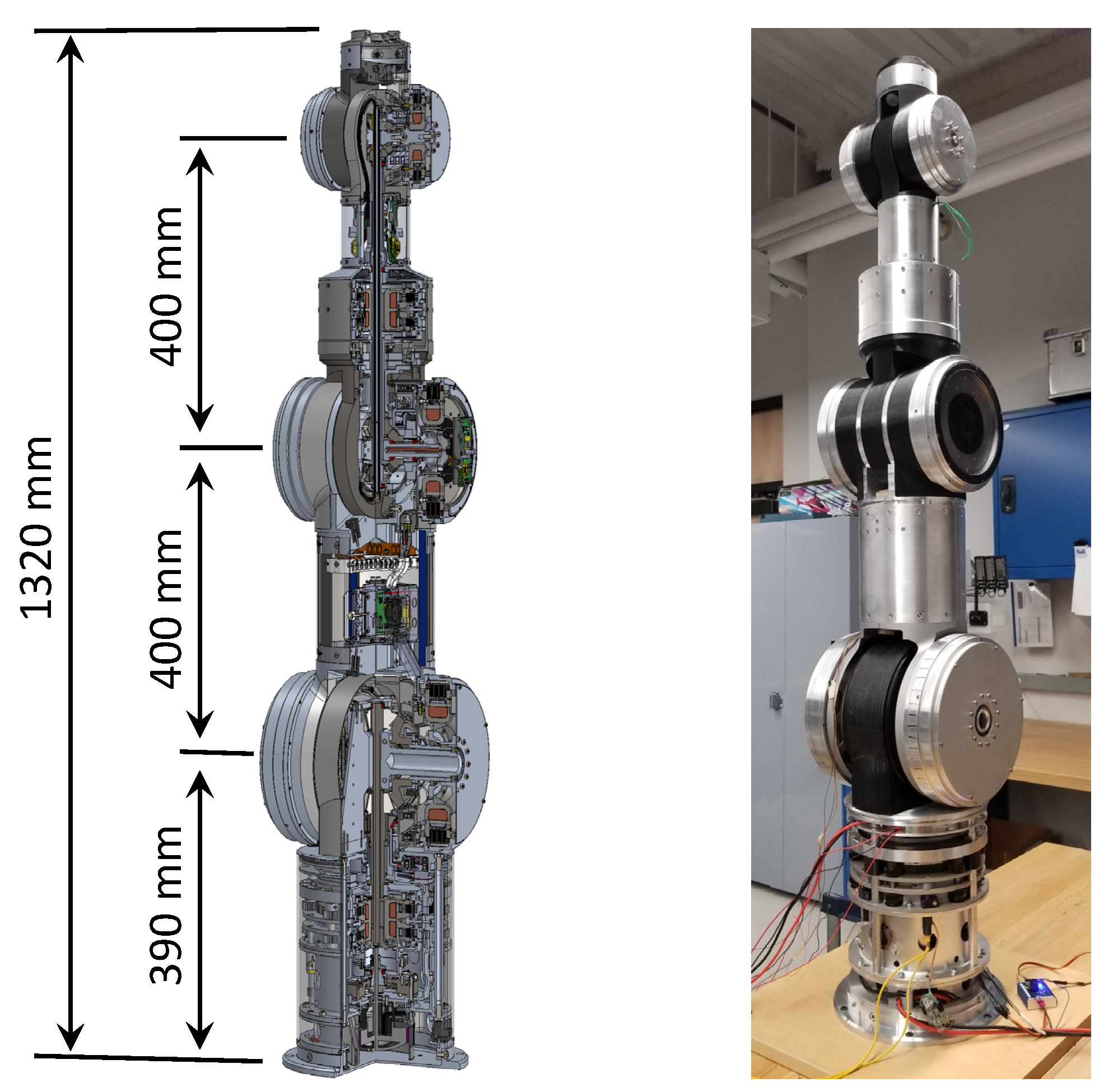
The experiments are conducted using the second joint of the 5-DOF manipulator in the configuration depicted in
Figure 8. Similar results could be obtained from other joints, as they are actuated similarly. Such results are not included to maintain brevity.
The experimental setup used to obtain the results in this section is illustrated in
Figure 9. The setup comprises a load cell (force/torque sensor ATI Gamma US-15-50) installed between the second link and the KUKA LWR 4+ robot flange to measure Joint 2 torque. Besides the MR clutch torque, the force/torque sensor readings contain other components, such as friction, inertial, and gravity forces. To minimize the impact of some (but not all) of these undesired components on the sensor measurements, the upper joints of the robot are removed during the experiments. Moreover, to improve the accuracy of the sensor readings, the gravity and inertial forces are computationally estimated and considered in subsequent calculations. The effect of gravity and inertial forces on the results are discussed and demonstrated later in this section.
Joint 2 (as well as each joint of the 5-DOF manipulator) is equipped with an Absolute 17-bit encoder from Zettlex to measure the angular position and velocity of the corresponding joint at a frequency of 10 kHz. Current control for each MR clutch is performed using the STM32F407VET6 microcontroller and a pair of H-bridge current drivers, TI DRV8874. The experimental data acquisition is performed using the same STM32F407VET6 microcontroller with measurements conducted at a sampling frequency of 1 kHz.
The 5-DOF robot is actuated by a single brushless DC motor (Hacker, model Q80-13XS F3A) with a harmonic gearbox (SHD-25-100-2SH). The motor and gearbox are positioned at the base of the robot which minimizes the moving inertia of the system.
5.1. Torque–Velocity Relationship
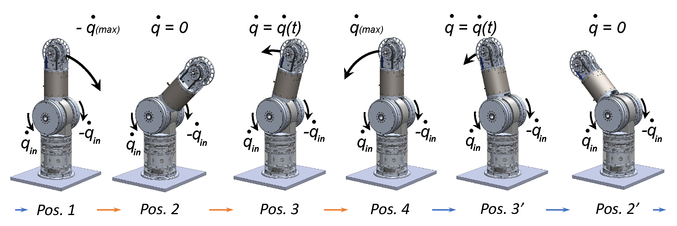
To obtain the relationship between the transmitted torque of an antagonistic MR clutch pair and its output velocity, the positive (CCW) and negative (CW) MR clutches in Joint 2 of the (modified) 5-DOF manipulator were used. During the experiment, joint 2 of the manipulator was moved externally by the KUKA robot back and forth, while one of the MR clutches in the pair was activated with a constant current. The sequence of robot poses representing the reciprocal motion of Joint 2 is shown in
Figure 10.
The external motion was selected in such a way that it forced the activated MR clutch into both active and braking states. To achieve this, the joint was moved by the external source so that the output velocity of the MR clutch (i.e., the joint velocity) during some areas of the movement exceeded its input velocity, i.e., .
The KUKA LWR 4+ robot attached to the second joint was used to move the joint within the
degree range from its upright position. At the same time, the positive (CCW) MR clutch was energized with a constant current of 0.2 A (corresponding to 15 N·m). The negative (CW) MR clutch was not activated. The input (rotor) velocity of the positive (CCW) MR clutch was set to 6 deg/s. Joint 2 was moved to reach a velocity of
deg/s during its motion. A similar experiment was repeated using the negative (CW) MR clutch. The results from these experiments are shown in
Figure 11.
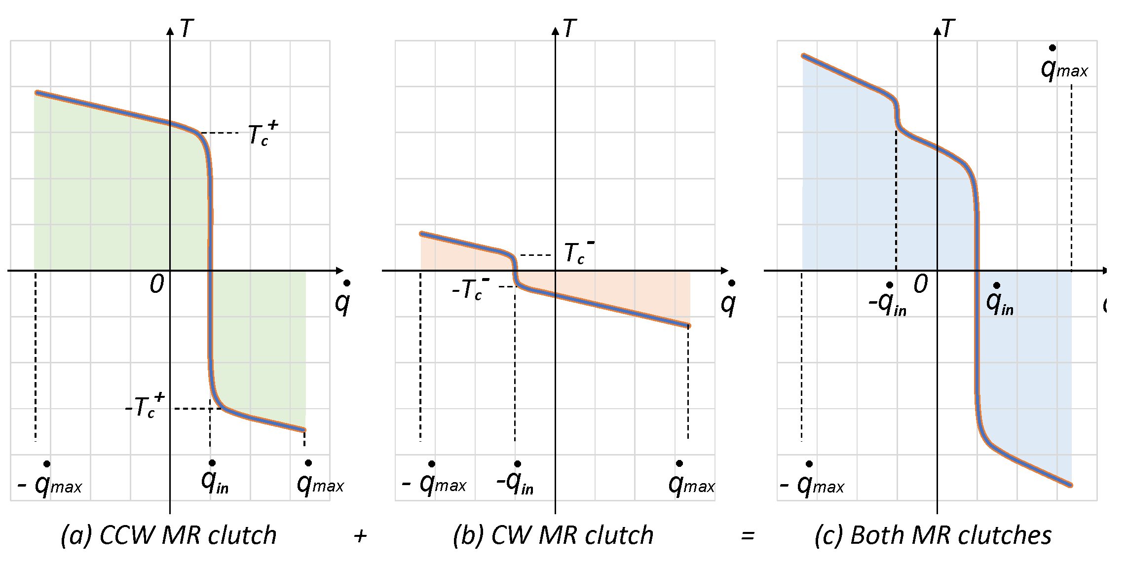
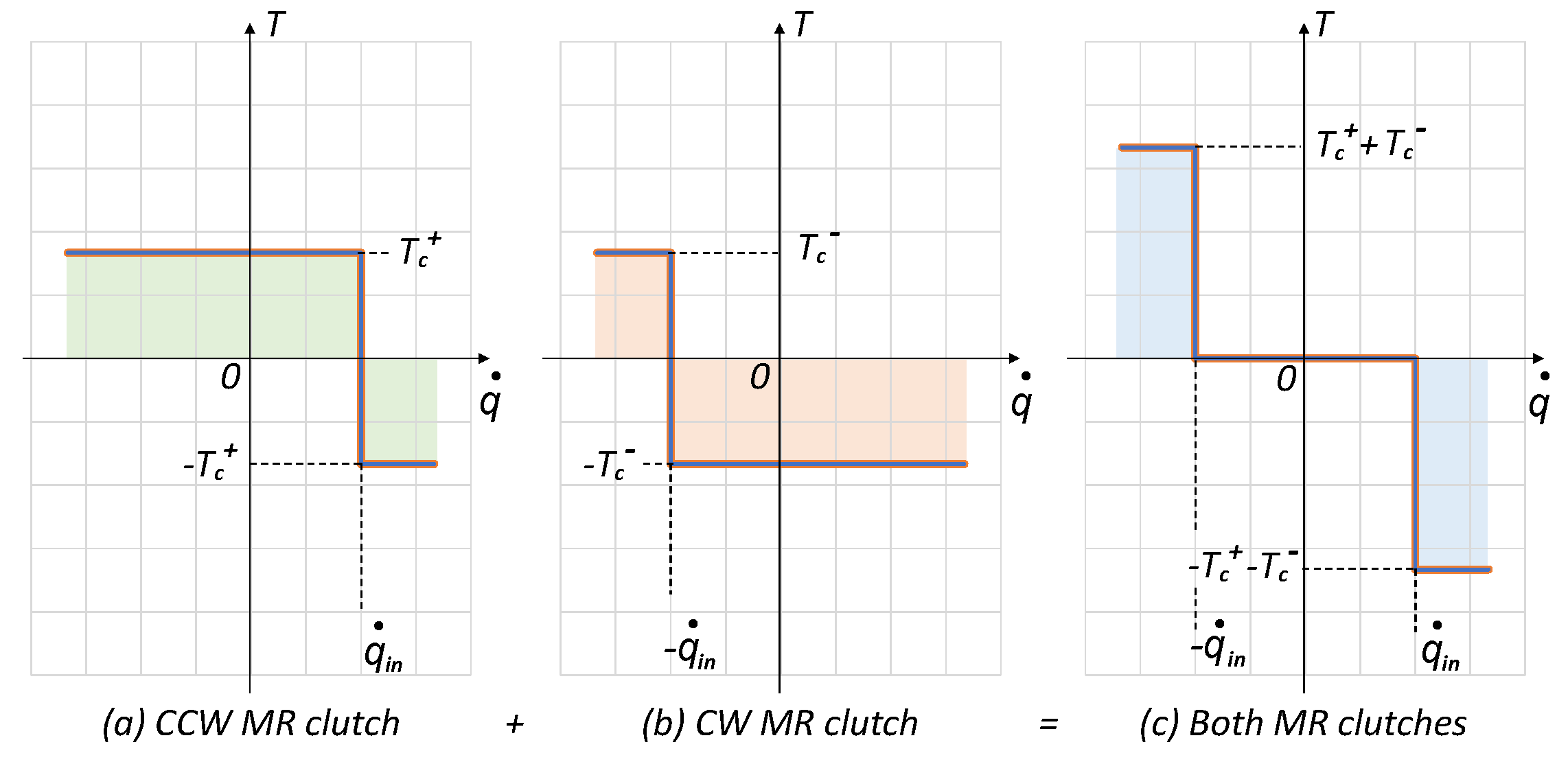
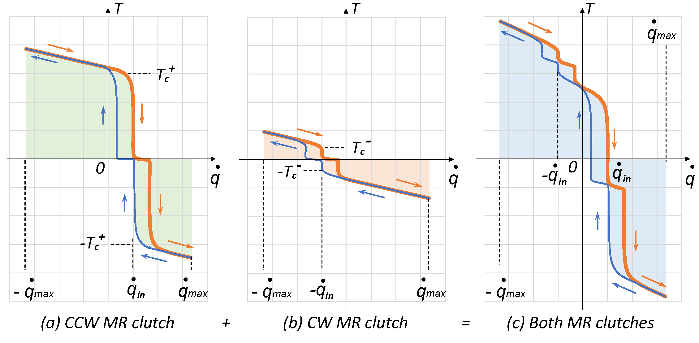
It is observed that the direction of the MR clutch output torque depends on the relative velocity between its input and output. This behavior was previously described and modeled in
Section 3.3 and
Section 3.4, respectively. In our experiment, the output torque of the MR clutches in the pair was set to
N·m, and their input velocity was set to
deg/s. One can clearly see the transition of the positive (CCW) MR clutch torque from 15 N·m to −15 N·m once its output velocity surpasses 6 deg/s. The opposite behavior is also seen for negative (CW) MR clutch below
deg/s.
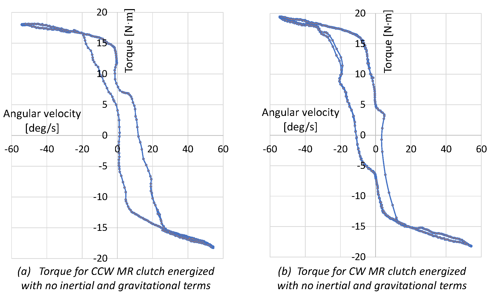
The torque–velocity curves appear with visible distortions in both regions. The distortions are due to the effect of gravity, friction, inertia (of Link 2), and structural flexibility on the measurements. The distortions in the low–velocity region of the curves are mostly due to the limited rigidity of the structure and the backlash in the mechanical transmission, both of which are difficult to model accurately. On the other hand, the distortions in the high-velocity region are mostly due to the inertial and gravitational forces which can be modeled with relatively good accuracy using the joint angle measurements and the known values of the robot masses. We estimated the inertial and gravity forces and subtracted these values from force/torque measurements. The corrected torque–velocity curves for both MR clutches after removing the effects of the inertial and gravity forces are shown in
Figure 12.
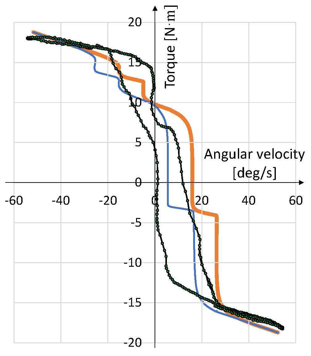
As seen, the torque–velocity curves more closely represent the relationship described in
Section 3.4. A comparison of the experimental torque–velocity curve of the positive (CCW) MR clutch with that obtained theoretically is shown in
Figure 13 and further validates the results.
As observed, there is a good match between the two curves at high-velocity regions where the effects of inertia and gravity forces were removed from the graph. The main mismatch between the two curves occurs in low-velocity regions where it is difficult to accurately model the effect of backlash and structural flexibility on the curves. Nonetheless, the results validate our modeling approach of the behavior of the antagonistic MR actuators.
5.2. Safe Control Strategy
In this section, we study the performance of the safe control strategy described in
Section 4.2. We selected an upper limit of 10 mJ for the kinetic energy of the robot. This value was arbitrarily selected for the purpose of demonstration only and has no significance. By using this value in (
15), an upper limit velocity for the motor was obtained to be 50 RPM. The motor velocity resulted in an input velocity of
deg/s for the positive and negative MR clutches in the second joint. The MR clutches in this joint were energized to move the robot link in a reciprocal motion with a constant velocity of
deg/s, similar to the motion shown in
Figure 10.
The difference with the previous experiment is that the robot motion is generated by its own actuators, i.e., the robot’s motor and its antagonistic MR clutches, rather than an external source (KUKA manipulator).
The KUKA LWR 4+ manipulator attached to the second link is used to introduce random external disturbances during the motion of the second joint. This enabled us to evaluate the performance of the controller for limiting the kinetic energy of the system through the inherent switching of MR clutches to the braking state. The KUKA robot moves along Link 2 trajectory in a compliant mode except that from time to time it exerts a disturbance torque that results in the second joint moving at a speed above the upper limit set by the controller (i.e., deg/s). The higher speed violated the limit for kinetic energy in the system permitted by the controller.
The results of this experiment are shown in
Figure 14. The figure includes the angular position and angular velocity of the second joint, the antagonistic torque of the MR clutch pair, and the total kinetic energy of the system.
The figure shows the expected motion of the joint as well as three different random perturbations caused by the KUKA robot. As seen, two perturbations (around 45 and 65 s) occurred during the clockwise rotation and forced the angular velocity of the joint from −6 deg/s to −24 deg/s momentarily. The third perturbation (around 95 s) occurred during the counter-clockwise rotation, forcing the velocity of the joint from 6 deg/s to about 39 deg/s momentarily.
Looking at the Kinetic energy graph, one can see that as soon as the velocity of either MR clutches surpasses the ±6 deg/s limits, the system kinetic energy crosses the 10 mJ threshold. This causes an immediate control reaction by instantaneous reversal of the direction of the applied torque by the corresponding MR clutch which subsequently forces the system to return to the active region by resisting the KUKA robot. Through this action, the controller limits the kinetic energy of the system to the desired value by reducing the output velocity below the set value. The braking states in the figure are marked with a red color background to highlight this inherent behavior. To better demonstrate the order in which the system responds to a kinetic energy limit violation, a small portion of the velocity, torque, and kinetic energy graphs are magnified. By looking at the exact time, it is observed that the increase in the velocity and kinetic energy is followed by the reversal of the torque direction.
The importance of these results is that the observed behavior occurs inherently, without relying on any sensor measurements, and is also independent of the state of the low-level control algorithm commanding the robot with MR actuators to follow the trajectory. The response is triggered as soon as the kinetic energy in the system, or equivalently the joint velocity, exceeds a predetermined threshold, at which point the corresponding MR clutch immediately acts as a brake with a torque that opposes the motion. The results clearly validate the uniform ultimate velocity boundedness of the MR actuation.
The results can be extended to multi-DOF actuation. However, it is beyond the scope of the current paper to describe its details and will be studied in future work.
6. Conclusions
In this paper, we presented a theoretical and experimental study on the intrinsic behavior of antagonistic Magneto-Rheological (MR) clutches.
The natural behavior of antagonistic MR clutches in bounding the output velocity was carefully examined. The study demonstrated the uniform ultimate boundedness of the velocity of antagonistic MR actuators in the presence of external disturbances. A graphical representation illustrating this behavior was provided, and the effects of undesired nonlinearities, such as mechanical backlash, yield stress variations, and viscosity of the MR fluid, were analyzed.
The theoretical findings were experimentally validated using a setup comprising a pair of antagonistic MR clutches in the second joint of a 5-DOF compliant robot and a KUKA LWR 4+ robot. The experiments confirmed that antagonistic MR actuators actively resist external sources and exhibit an inherent tendency to maintain an active state while limiting the output velocity.
Notably, the study’s broader implications support our earlier claims regarding the suitability of MR actuation for safe, intuitive, and reliable actuation, without the complexities and high costs associated with alternative approaches. The results highlight the suitability of MR actuators and demonstrate the potential for designing systems that exhibit safe and reliable behavior throughout the control region, without compromising actuation performance or incurring excessive design costs.


