Hybrid Solenoids Based on Magnetic Shape Memory Alloys
Abstract
1. Introduction
1.1. Motivation
1.2. Content Overview
2. State of the Art
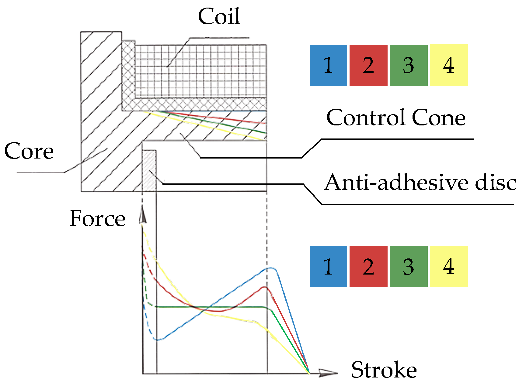
2.1. Methods for Influencing the Characteristic Force–Displacement Characteristics of a Solenoid
2.2. Basics of MSM Alloys
3. Modelling of the Actuator Concept and Derivation of Performance Expectations
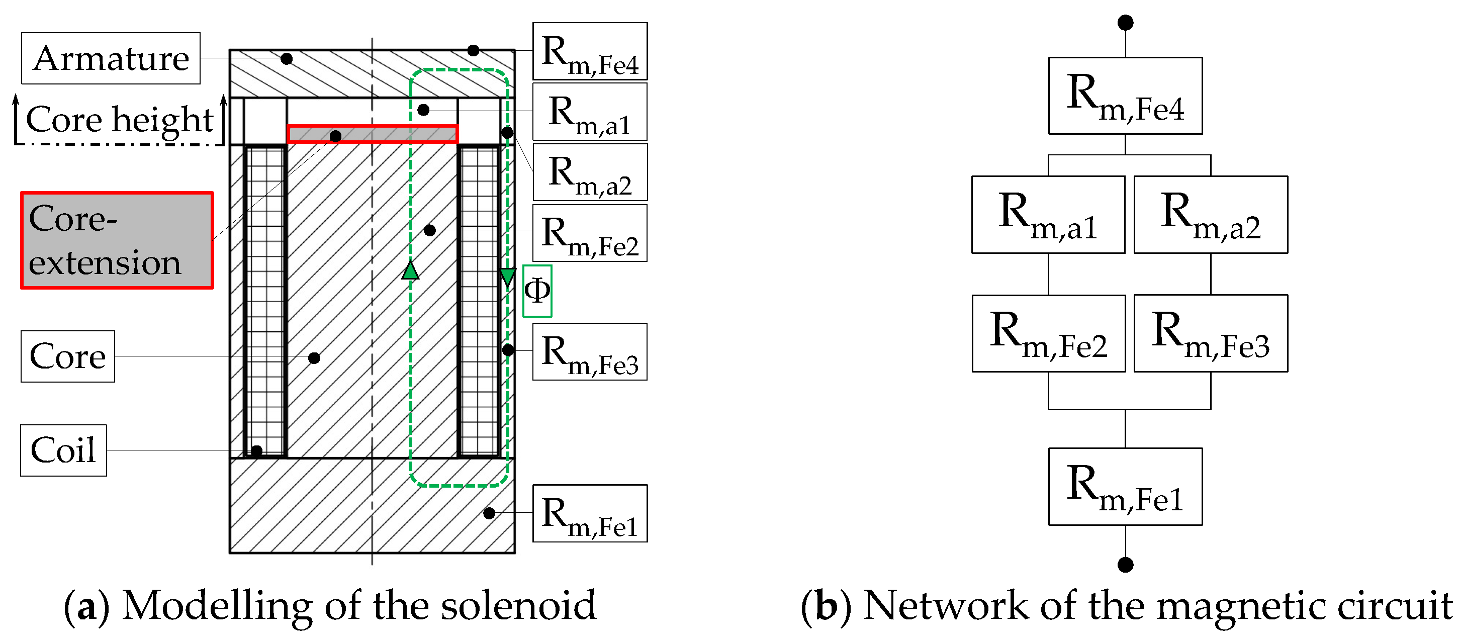
3.1. Matlab/Simulink Model of the Actuator Concept
3.2. Performance Expectations of the Solenoid
3.3. Presentation of the Basic Switching Principle
4. Simulation Study with Two Different Actuator Variants
4.1. Materials and Methods
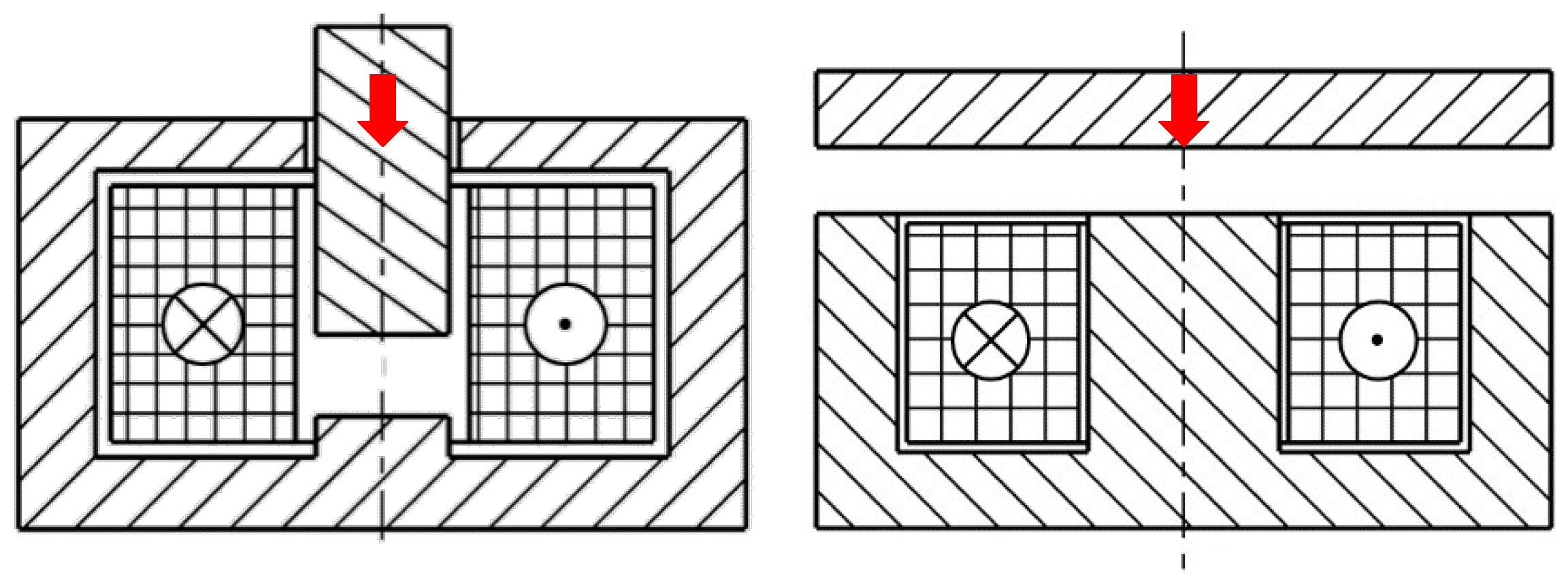
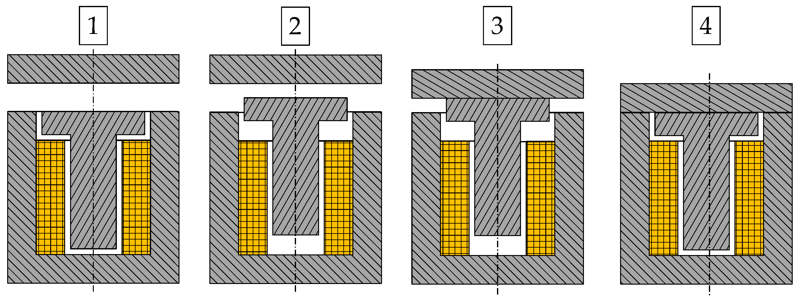
4.2. Introduction of the Two Actuator Setups

4.3. Parameter Variations
- Variations in the dimensions of the flux guidance were intended to find suitable magnetic excitation within the MSM stick while avoiding undesired flux paths and saturation effects. The dimensions of the armature and the solenoid’s body were not varied for either variant but were fixed at a value of 4 mm to rule out magnetic saturation within the limits of the specific electrical excitation.
- Geometric dimensions of the coil and the current density applied were varied to find both the necessary excitation for a sufficient magnetic flux in the MSM stick and the relation of force created to applied excitation.
- Upper and lower end positions of the armature and plunger movements were combined to create initial, activated and closed states of the switching operation of the actuator. For the concept with a horizontally aligned MSM stick, transmission was not enabled, and the stroke of the plunger was identical to the vertical variant.
4.4. Evaluation of the Flux Density in the MSM Sticks
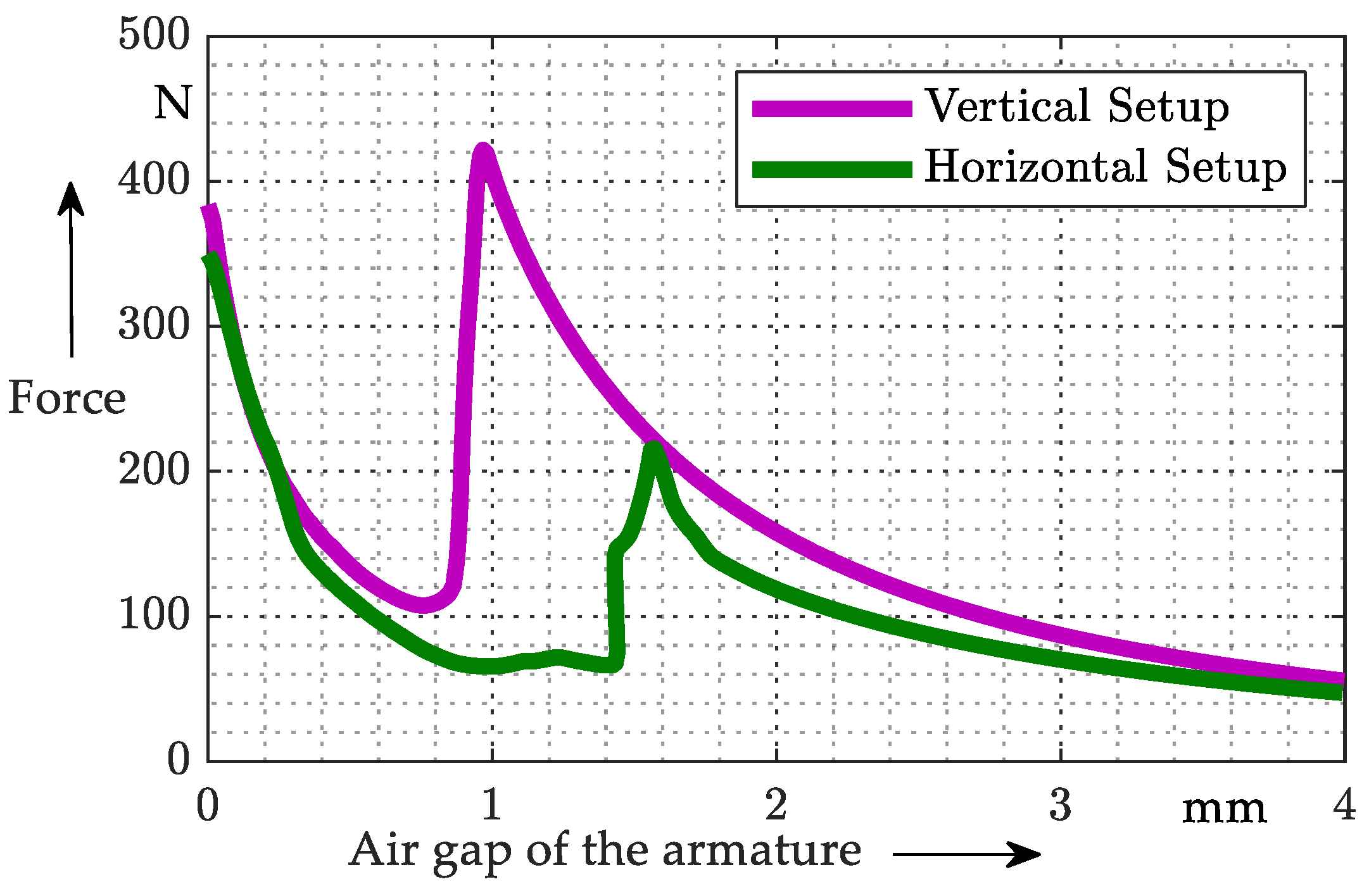
4.5. Evaluation of the Force on Armature
5. Prototypes
5.1. Materials and Methods
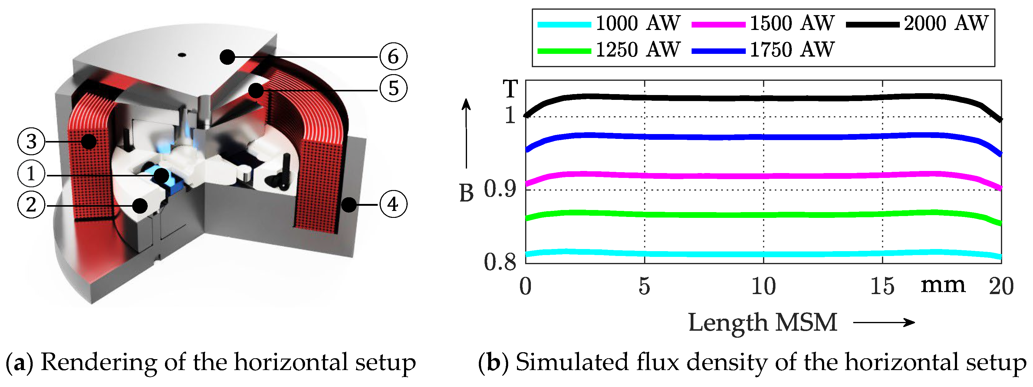
5.2. CAE Prototyping for the Horizontal Setup
5.3. CAE Prototyping for the Vertical Setup
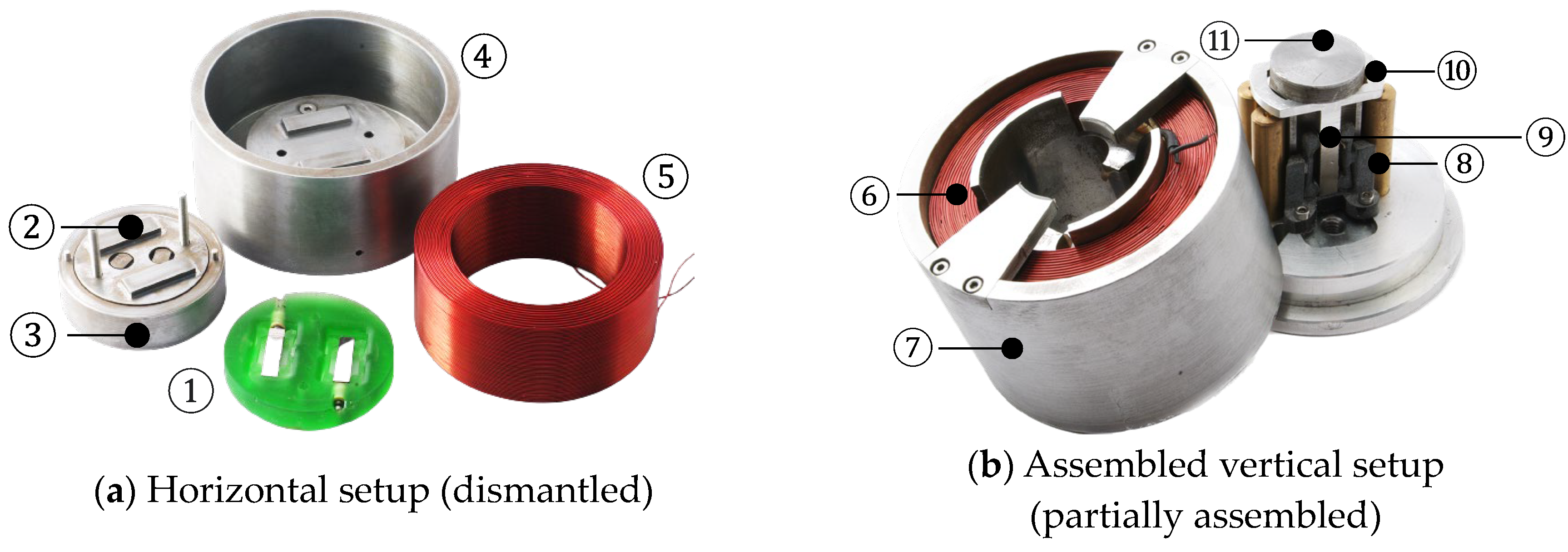
5.4. Presentation of the Manufactured Prototypes
6. Characterization
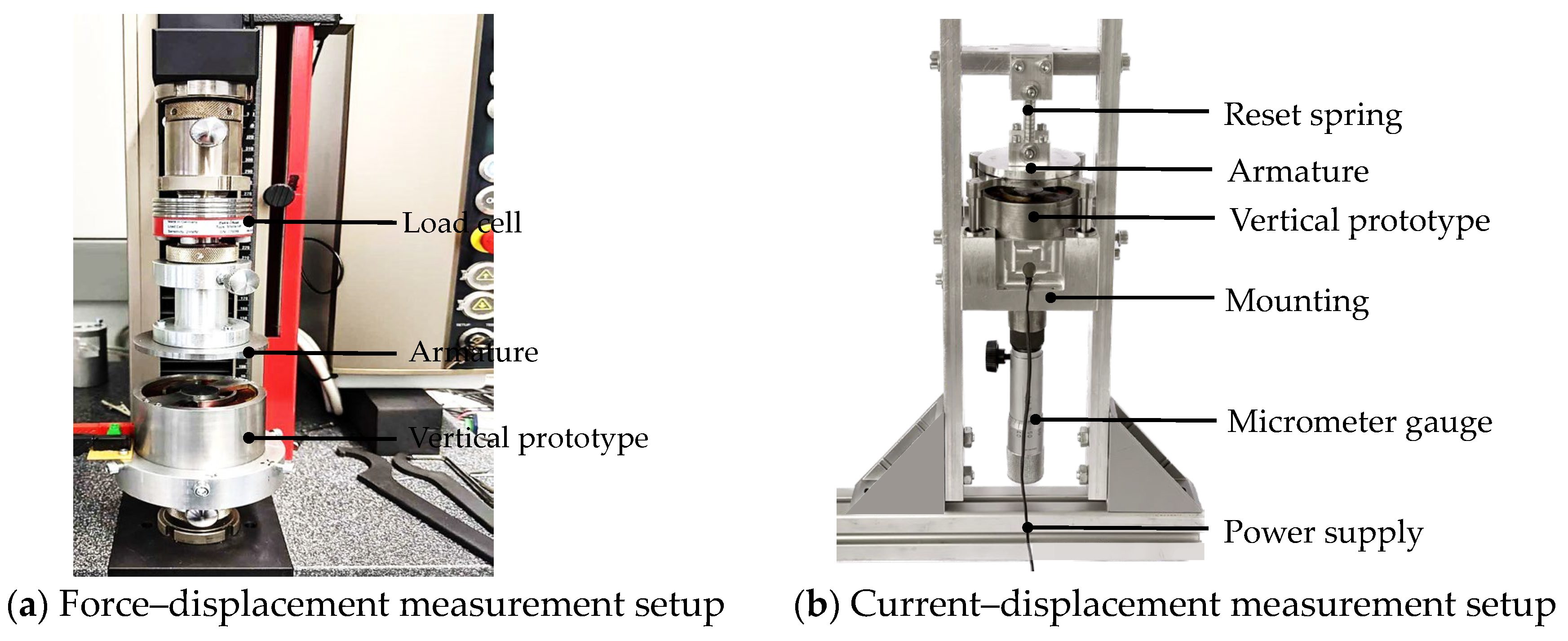
6.1. The Measurement Setups
6.2. Presentation and Discussion of the Results
6.2.1. Force–Displacement Characteristic
6.2.2. Current–Displacement Characteristic
7. Discussion and Conclusions
Author Contributions
Funding
Institutional Review Board Statement
Data Availability Statement
Conflicts of Interest
References
- Mauch, M.; Hutter, M.; Gundelsweiler, B. Development of an Electromagnetic Actuator with Magnetic Shape Memory Active Core for Stroke Enlargement and Noise Reduction; VDE Verlag: Berlin, Germany, 2021. [Google Scholar]
- Gundelsweiler, B.; Mauch, M.; Raab, M. Aktor Mit Aktivem Kern. Germany Patent DE102019218567B3_1, 6 May 2021. [Google Scholar]
- Gundelsweiler, B.; Mauch, M. Elektromagnetischer Hub- und/oder Haft-Aktor. Germany Patent DE102021124654A1, 3 November 2022. [Google Scholar]
- Mauch, M.; Gundelsweiler, B. Design of a hybrid electromagnetic switching/holding solenoid with adjustable core. In Proceedings of the IKMT 2022, 13. GMM/ETG-Symposium. Linz, Austria, 14–15 September 2022; pp. 1–6. [Google Scholar]
- Ullakko, K.; Huang, J.K.; Kantner, C.; O’handley, R.C.; Kokorin, V.V. Large magnetic-field-induced strains in Ni2MnGa single crystals. Appl. Phys. Lett. 1996, 69, 1966–1968. [Google Scholar] [CrossRef]
- ETO GRUPPE TECHNOLOGIES GmbH. Magnetoshape. Available online: https://www.etogruppe.com/unternehmen/magnetoshape-r.html (accessed on 27 March 2023).
- Hubert, A.; Calchand, N.; Le Gorrec, Y.; Gauthier, J.-Y. Magnetic Shape Memory Alloys as smart materials for micro-positioning devices. Adv. Electromagn. 2012, 1, 75–84. [Google Scholar] [CrossRef]
- Schlüter, K.; Holz, B.; Raatz, A. Principle Design of Actuators Driven by Magnetic Shape Memory Alloys. Adv. Eng. Mater. 2012, 14, 682–686. [Google Scholar] [CrossRef]
- Linsmeier, K.-D. Elektromagnetische Aktoren: Physikalische Grundlagen, Bauarten, Anwendungen; Die Bibliothek der Technik 118; Verlag Moderne Industrie: Landsberg am Lech, Germany, 1995. [Google Scholar]
- Kallenbach, E.; Eick, R.; Ströhla, T.; Feindt, K.; Kallenbach, M.; Radler, O. Elektromagnete; Springer Fachmedien Wiesbaden: Wiesbaden, Germany, 2018. [Google Scholar]
- Gabdullin, N.; Khan, S.H. Review of properties of magnetic shape memory (MSM) alloys and MSM actuator designs. J. Phys. Conf. Ser. 2015, 588, 012052. [Google Scholar] [CrossRef]
- Happel, J.; Pagounis, E.; Schnetzler, R.; Heider, J.; Laufenberg, M. Multistable proportional valve: An energy efficient approach for high temperature passive magnetic shape memory applications. In Proceedings of the ACTUATOR; International Conference and Exhibition on New Actuator Systems and Applications 2021, Online, 17–19 February 2021; pp. 1–3. [Google Scholar]
- Raab, M.; Hutter, M.; Kazi, A.; Schinkoethe, W.; Gundelsweiler, B. Magnetically Levitated Linear Drive Using an Active Gravity Compensation Based on Hybrid Shape Memory Actuators. IEEE/ASME Trans. Mechatron. 2021, 26, 1380–1391. [Google Scholar] [CrossRef]
- Holz, B.; Riccardi, L.; Janocha, H.; Naso, D. MSM Actuator: Design Rules and Control Strategies. Adv. Eng. Mater. 2012, 14, 668–681. [Google Scholar] [CrossRef]
- Gauthier, J.-Y.; Hubert, A.; Abadie, J.; Chailet, N.; Lexcellent, C. Magnetic Shape Memory Alloy and Actuator Design. In Proceedings of the 5th International Workshop on Microfactories, IWMF’06, Besançon, France, 25–27 October 2006. [Google Scholar]
- Schiepp, T.; Pagounis, E.; Laufenberg, M. Magnetic Shape Memory Actuators for Fluidic Applications. In Proceedings of the 9th International Fluid Power Conference, Aachen, Germany, 24–26 March 2014. [Google Scholar] [CrossRef]
- Effner, A.; Zawada, T.; Weber, J. A Design Approach for a Valve Based on a Magnetic Shape Memory Actuator. Shape Mem. Superelasticity 2020, 6, 107–114. [Google Scholar] [CrossRef]
- Wegener, K.; Blumenthal, P.; Raatz, A. Development of a miniaturized clamping device driven by magnetic shape memory alloys. J. Intell. Mater. Syst. Struct. 2014, 25, 1062–1068. [Google Scholar] [CrossRef]
- Gauthier, J.Y.; Hubert, A.; Abadie, J.; Lexcellent, C.; Chaillet, N. Multistable actuator based on magnetic shape memory alloy. In Proceedings of the 10th International Conference on New Actuators, ACTUATOR’06, Bremen, Germany, 14–16 June 2006; pp. 787–790. [Google Scholar]
- Smith, A.R.; Fologea, D.; Mullner, P. Magnetically Driven Pump for Solid-state Microfluidic Flow Control. In Proceedings of the ACTUATOR 2018; 16th International Conference on New Actuators, Bremen, Germany, 25–27 June 2018; pp. 1–2. [Google Scholar]
- Happel, J.; Schnetzler, R.; Laufenberg, M. Intelligent force-controlled miniature gripper driven by magnetic shape memory alloy. In Proceedings of the ACTUATOR 2022; International Conference and Exhibition on New Actuator Systems and Applications, Mannheim, Germany, 29–30 June 2022. [Google Scholar]
- Hutter, M.; Gundelsweiler, B. Analysis of the impact of mechanical guidance on active MSM-stick elongation behavior. In Proceedings of the ACTUATOR 2022; International Conference and Exhibition on New Actuator Systems and Applications, Mannheim, Germany, 29–30 June 2022; pp. 1–4. [Google Scholar]









| Xg | Xi | Y4 | Y3 | Y2 | Y1 | X2 | X1 | Y1 | |
|---|---|---|---|---|---|---|---|---|---|
| Vertical | - | - | - | - | - | - | 10 … 20 | 0 … 8.5 | 0 … 2 |
| Horizontal | 3 … 9 | 26 … 38 | 2 … 10 | 1 … 5 | 1 … 5 | 2 … 10 | - | - | - |
| Yc | Xc | |
|---|---|---|
| Vertical | 25 … 35 | 5 … 15 |
| Horizontal | 9 … 33 | 10 … 16 |
| d | s | |
|---|---|---|
| Vertical | 0 … 1.5 | 0 … 1 |
| Horizontal | 0 … 1.5 | 0 … 1 |
| Horizontal | Vertical | |
|---|---|---|
| Avg | 1.1599 | 1.2409 |
| Max | 1.8084 | 1.8145 |
| Min | 1.0950 | 1.0976 |
| Parameters | Description | Unit | Aim | Weighting |
|---|---|---|---|---|
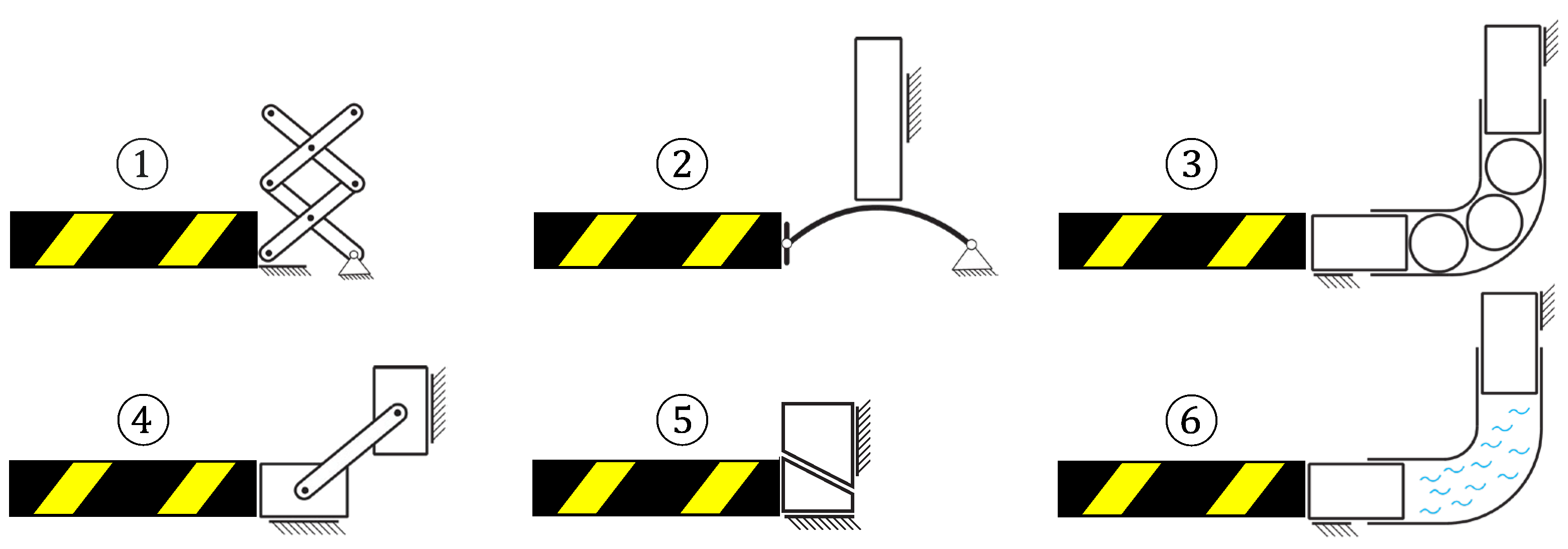
| Fm,2 | Maxwell’s tensile force on the armature in step 2 (the ‘steps’ to describe the parameters refer to Figure 7) | N | ↑ | 0.16 |
| ∆Fm,12 | Difference of Maxwell’s tensile force on the anchor between step 1 and step 2 | N | ↑ | 0.12 |
| Fm,4 | Maximum holding force of the solenoid in step 4 | N | ↑ | 0.14 |
| BMSM,1 | Y-component of the magnetic flux density, the average value of which is formed over the measuring area immediately in front of the MSM stick in state 1 | T | ↑ | 0.16 |
| ∆BMSM,1 | Difference of the mean value of the Y-component of the magnetic flux density between the two measuring surfaces in state 1 | T | ↓ | 0.12 |
| BMSM,4 | Magnetic flux density in step 4 | T | ↑ | 0.07 |
| Fm,2,d=10 | Maxwell’s tensile force on the armature in step 2 at | N | ↑ | 0.05 |
| ∆Bd=10 | Reduction of the magnetic flux density at the measuring surfaces of the MSM sticks at | T | ↓ | 0.05 |
| s | Preload on the individual MSM stick at | N/mm2 | ↓ | 0.10 |
| Effort for design, manufacturing and assembly (Designing) | - | ↓ | 0.03 | |
| Units | Concept 1 | Concept 2 | Concept 3 | Concept 4 | Concept 5 | Concept 6 | |
|---|---|---|---|---|---|---|---|
| windings 1 | - | 1814 | 898 | 737 | 1584 | 1948 | 772 |
| windings 2 | - | - | 576 | 742 | - | - | 772 |
| Fm,2 | N | −26.04 | −5.70 | −7.63 | −18.30 | −29.09 | −20.56 |
| Points | 5 | 0 | 1 | 2 | 6 | 3 | |
| ∆Fm,12 | N | −5.2 | −1.73 | −0.87 | −4.41 | −7.25 | −5.86 |
| Points | 3 | 1 | 0 | 2 | 6 | 4 | |
| Fm,4 | N | −906.38 | −411.13 | −923.78 | −802.98 | −853.81 | −1102.25 |
| Points | 3 | 0 | 4 | 1 | 2 | 5 | |
| BMSM,1 | T | 0.61 | 0.67 | 0.64 | 0.66 | 0.59 | 0.55 |
| Points | 3 | 6 | 4 | 5 | 2 | 1 | |
| ∆BMSM,1 | T | 0.1 | 0 T | 0.02 | 0.05 | 0.03 | 0.08 |
| Points | 1 | 6 | 5 | 3 | 4 | 2 | |
| BMSM,4 | T | 0.67 | 0.74 | 0.56 | 0.84 | 0.84 | 0.58 |
| Points | 4 | 5 | 1 | 6 | 6 | 2 | |
| Fm,2,d=10 | N | −6.14 | −1.23 | −1.46 | −4.25 | −7.51 | −4.36 |
| Points | 5 | 0 | 1 | 2 | 6 | 3 | |
| ∆Bd=10 | T | 0.03 | 0 | 0 | 0.04 | 0.05 | 0.01 |
| Points | 4 | 6 | 6 | 3 | 3 | 5 | |
| s | N/mm2 | 0.13 | 0.03 | 0.04 | 0.05 | 0 | 0.19 |
| Points | 2 | 5 | 4 | 3 | 6 | 1 | |
| Designing | Points | 6 | 1 | 4 | 1 | 2 | 5 |
| x (Acc. to Formula (3)) | 0.55 | 0.5 | 0.48 | 0.48 | 0.72 | 0.48 |
Disclaimer/Publisher’s Note: The statements, opinions and data contained in all publications are solely those of the individual author(s) and contributor(s) and not of MDPI and/or the editor(s). MDPI and/or the editor(s) disclaim responsibility for any injury to people or property resulting from any ideas, methods, instructions or products referred to in the content. |
© 2023 by the authors. Licensee MDPI, Basel, Switzerland. This article is an open access article distributed under the terms and conditions of the Creative Commons Attribution (CC BY) license (https://creativecommons.org/licenses/by/4.0/).
Share and Cite
Mauch, M.; Hutter, M.; Gundelsweiler, B. Hybrid Solenoids Based on Magnetic Shape Memory Alloys. Actuators 2023, 12, 328. https://doi.org/10.3390/act12080328
Mauch M, Hutter M, Gundelsweiler B. Hybrid Solenoids Based on Magnetic Shape Memory Alloys. Actuators. 2023; 12(8):328. https://doi.org/10.3390/act12080328
Chicago/Turabian StyleMauch, Manuel, Marco Hutter, and Bernd Gundelsweiler. 2023. "Hybrid Solenoids Based on Magnetic Shape Memory Alloys" Actuators 12, no. 8: 328. https://doi.org/10.3390/act12080328
APA StyleMauch, M., Hutter, M., & Gundelsweiler, B. (2023). Hybrid Solenoids Based on Magnetic Shape Memory Alloys. Actuators, 12(8), 328. https://doi.org/10.3390/act12080328


