Article

Comfort-Oriented Semi-Active Suspension Configuration with Inerter-Based Network Synthesis

1
Faculty of Mechanical and Electrical Engineering, Kunming University of Science and Technology, Kunming 650504, China
2
Yunnan International Joint Laboratory of Intelligent Control and Application of Advanced Equipment, Kunming 650504, China
3
Yunnan Dahongshan Pipeline Co., Ltd., Kunming 650302, China
*
Author to whom correspondence should be addressed.
Actuators 2023, 12(7), 290; https://doi.org/10.3390/act12070290
Submission received: 1 June 2023 / Revised: 5 July 2023 / Accepted: 12 July 2023 / Published: 16 July 2023
(This article belongs to the Section Actuators for Land Transport)

Abstract

:
This paper presents a comfort-oriented semi-active suspension system composed of a network-synthesized passive section and a controllable section based on a semi-active inerter. Firstly, the semi-active suspension system is divided into a passive part and a controllable part. For the passive part, first-order and second-order robust positive real controllers are designed. The problem with H 2 cost is considered, and the bilinear matrix inequalities (BMI) are solved using an iterative method to obtain two admittance functions. The admittance functions are physically realized as two mechanical networks composed of mechanical passive elements such as inerter, spring, and damper (ISD). Then, the parameters of these mechanical elements in those networks are optimized by Particle Swarm Optimization (PSO). Secondly, a semi-active inerter based on Sky-hook control is introduced for the semi-active part of the suspension system. Finally, the semi-active ISD suspension structure is verified by a quarter vehicle model. The simulation results show that the first-order and second-order suspension systems optimize the RMS of the spring mass acceleration by 14.2% and 23.9%, respectively, as compared to traditional suspension systems. Furthermore, frequency-domain analysis also shows that both suspension systems effectively reduce the value of spring mass acceleration in the low-frequency band.

1. Introduction

The vehicle suspension system plays a crucial role in supporting the static weight of a vehicle while determining its overall performance regarding the ride-comfort and road-holding. Nowadays, vehicle suspension systems can be categorized into three types: passive suspension, semi-active suspension, and active suspension. Active suspension provides optimal performance but also requires a lot of energy to drive [1]. Passive suspension is less expensive and does not require additional energy input to operate compared to active suspension. However, passive suspension has limitations when a vehicle requires greater performance [2]. Comparatively, a semi-active suspension can provide better performance than passive suspension while incurring less energy consumption compared to an active suspension [3,4,5]. To achieve the required performance, semi-active suspensions mainly utilize adjustable mechanical elements, such as semi-active damping [6,7,8], a semi-active spring [9], or a semi-active inerter [10,11].
In recent years, network synthesis has regained its position as a research hotspot with the proposal of the inerter [12]. The emergence of inerters has completed the mechanical–electrical analogy, making it possible to apply electrical network synthesis to mechanical networks [13,14]. Papageorgiou and Smith [15] were the first to propose a procedure for the synthesis of positive real controllers based on matrix inequalities, in which the H 2 and H problems were considered. Passive elements were used to realize the admittance function. The feasibility of this procedure was verified in the design of quarter vehicle passive suspension. Chen et al. [16] investigated the effect of admittance functions of different orders on the performance of the suspension system, finding that the performance improves with an increase in the order of the admittance functions, but the structure also becomes more complex. Wang et al. [17], using up to four elements, investigated the network synthesis problem of biquadratic impedances and derived the sufficient conditions for the implementation of arbitrary biquadratic impedances. Chen et al. [18] designed the structure of the ISD suspension system using Linear Matrix Inequality (LMI) and optimized the ISD suspension using the quantum genetic algorithm. Through simulations, they demonstrated that the suspension performance can effectively reduce the spring mass acceleration in the low-frequency band. Based on the inerter, Jason et al. [19] analyzed the positive-real biquadratic functions that can be implemented by five components in mechanical networks, and provided their implementable conditions. Based on the research above, the method of combining the inerter, spring, and damping to construct various structural forms has shifted from the “structural method” to the “impedance method”, also known as the “black box method” [20,21,22].
For traditional semi-active suspensions, the usual focus to improve their performance is on the semi-active control algorithm and optimization [23]. However, with the advent of the inerter, a semi-active inerter can be used instead of a semi-active spring or semi-active damping. Hu et al. [24] proposed a ball-screw semi-active inerter that can continuously adjust its inertance by adjusting the radius of the flywheel. Li et al. [25] investigated semi-active suspension with a controlled inerter and designed an H 2 state feedback controller. This resulted in a substantial reduction in the sprung mass acceleration on the spring at the intrinsic body frequency. Overall, it is clear that suspension systems with semi-active inerter can perform better than traditional suspension systems. To further explore this technique, in this paper, we design a semi-active ISD suspension using network synthesis, where we introduce a semi-active inerter under Sky-hook control.
This article is organized as follows. In Section 2, we model and analyze the proposed semi-active ISD suspension based on the quarter vehicle model. We will also obtain the positive real controller’s BMI corresponding to it. In Section 3, we solve the LMI and implement the solution to obtain the passive configuration of the considered suspension. In Section 4, the parameters of the mechanical network from Section 3 are optimized using PSO. In Section 5, we introduce the semi-active Sky-hook control law and simulate the suspension’s overall performance for analysis. Section 6 concludes the paper.

2. Models of Semi-Active ISD Suspension

2.1. Quarter Vehicle Suspension

The quarter vehicle model considered in this paper is shown in Figure 1a, where m s , m u , and k t denote the sprung mass, unsprung mass, and tire stiffness, respectively, and b s k y is the ideal Sky-hook inertance. The sprung mass displacement, the unsprung mass displacement and the road excitation are denoted by z s , z u , and z r , respectively. k represents the support spring. The suspension system between the sprung mass and unsprung mass discussed in this paper is divided into two parallel parts: the passive part and semi-active part. The passive part is composed of a support spring k and a mechanical network K ( s ) , while the semi-active part is on the ideal Sky-hook inerter. Figure 1b shows the traditional semi-active suspension as a reference model, where c s e m i is a semi-active damper coefficient.
For the suspension system considered in this paper, the admittance of the entire passive part can be expressed as W ( s ) = k / s + K ( s ) . In addition, for the semi-active part, the ideal Sky-hook inerter [26] is chosen, and when the structural optimization of the passive part is completed, the ideal Sky-hook inerter will be realized using the semi-active method in order to facilitate the calculation of parameters.
According to Newton’s second law, the kinetic equation of semi-active ISD suspension can be written in the following form:
z ¨ u m z + k ( z s z u ) + F d = 0 z ¨ u m u + k t ( z u z r ) k ( z s z u ) F d = 0 F ^ d = K ( s ) ( s z ^ s s z ^ u ) m z = m s + b s k y
where F d is the force transferred by the mechanical network K ( s ) , and F ^ d , z ^ s and z ^ u are the L a p l a c e transform of F d , z s and z u , respectively.
Selecting state variables x = [ z s , z ˙ s , z u , z ˙ u ] T , input u = [ F d , z r ] T , output y = [ z ˙ s , z s , z ˙ s z ˙ u ] T , respectively, kinetic equation for (1) can be written as the following state-space expression:
x ˙ = A x + B F d z r , y = C x ,
where
A = 0 1 0 0 k / m z 0 k / m z 0 0 0 0 1 k / m u 0 ( k + k t ) / m u 0 , B = 0 0 1 / m z 0 0 0 1 / m u k t / m u , C = 0 1 0 0 1 0 0 0 0 1 0 1 .

2.2. Passive Network Synthesis

According to [15], passive networks can be physically implemented using a spring, damper, and inerter when the transfer functions of the mechanical networks formed by their series–parallel connections are positive real. The form of admittance K ( s ) for the spring, damper, and inerter can be represented by k / s , c, and b s , respectively.
The following matrix inequality gives the positive real condition for the controller: Given that K ( s )
K ( s ) = A k B k C k D k = C k ( s I A k ) 1 B k + D k
then, K ( s ) is positive real if and only if there exists P k = P k T > 0 that satisfies the following LMI [27]:
A k T P k + P k A k P k B k C k T B k T P k C k D k T D k 0

2.3. Design of Positive Real Controller

Generally, the structure of the passive part K ( s ) is designed in two ways: In the first approach, a finite number of mechanical components is selected and combined in different arrangements, and the other one is formed using a network synthesis method, commonly known as the “black box method” for network construction. In this paper, the network synthesis method is used to design the passive part of the structure. It can directly lead to the network without the need for comparison work, unlike the first approach.
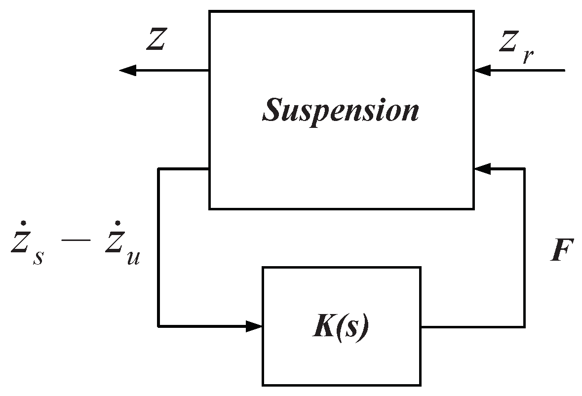
The passive mechanical network is treated as a positive real controller in this paper, as shown in Figure 2. The solution of the derivative function will be transformed into the design of a positive real controller. For a given K ( s ) with order of n k , the state space expression of the passive network part K ( s ) can be written in the following form:
x ˙ k = A k x k + B k ( z ˙ s z ˙ u ) F d = C k x k + D k ( z ˙ s z ˙ u )
where F d and z ˙ s z ˙ u are the output and input of the controller; x k is the state vector of the controller; and A k , B k , C k , and D k are parameter matrices for substitution. Combining (2) and (5), a closed-loop system is obtained in the form of the following state-space expressions:
x ˙ c l = A c l x c l + B c l z r z ˙ s = C c l x c l
where, A c l = A + B 1 D k C 3 B 1 C k B k C 3 A k , B c l = B 2 0 n k , C c l = C 1 0 n k T , x c l = [ x , x k ] T . z r is the system input, and z ˙ s is the system output. B 1 and B 2 denote the first and second columns of matrix B in (2); C 1 and C 3 denote the first and third rows of matrix C in (2); and A represents the matrix A in (2), while 0 n k denotes a column vector of dimension n k with all 0 elements.
There exists a positive real controller K ( s ) of order n k such that the A c l in closed-loop system is stable and T z ^ r s z ^ s 2 < λ when, and only if, there exists P c l = P c l T > 0 , X k = X k T > 0 satisfying the following LMI [15]:
A c l P c l + P c l A c l P c l B c l B c l T P c l I < 0 , P c l C c l T C c l Q > 0 , t r ( Q ) < λ 2 , A k T X k + X k A k X k B k C k T B k T X k C k D k T D k 0 .
The first three LMIs are necessary and sufficient conditions for the existence of a stabilizing controller. The fourth LMI further restricts the controller to be positive real. In both of the above LMIs, each LMI contains the product of two unknown matrixes, so these problems are bilinear matrix inequality problems (BMI). Compared to LMI, BMI is a non-convex, NP-hard problem and is more difficult to solve with the traditional LMI algorithm [18]. The details of solving BMI will be discussed in Section 3.2.

3. Network Synthesis of the Passive Part

In this section, both the first-order and second-order positive real controllers are optimized to improve the ride comfort, and the result obtained from the optimization is physically implemented.

3.1. Description of Suspension Performance

Ride comfort, road-holding, and suspension technological limitations are three main performance indices for a suspension system. Note that they are also contradictory factors to improve at the same time. For the design of suspension systems, these indices can be expressed in terms of the sprung acceleration, the tire dynamic load, and the suspension deflection, respectively [2].
In this paper, the design of the suspension is preferential to ride comfort. As shown in [28], the Root Mean Square (RMS) value of the mass on the spring can be expressed in the following form:
J = 2 π ( V κ ) 1 / 2 s T z ^ r z ^ s 2 ,
where V is the forward speed of vehicle, κ is the road surface roughness, and T z ^ r z ^ s represents the transfer function between the road excitation z r to the sprung mass displacement z s .
In order to reduce the acceleration of the sprung mass and improve the ride comfort, the network synthesis problem of the ISD suspension can be converted into the minimum value of T z r z ˙ s 2 if the conditions in Theorem 2 are satisfied.

3.2. Solve BMI and Network Synthesis

We consider an instance of the general BMI problem given by (7); the Genetic Algorithm (GA) is introduced to perform the optimization. As a stochastic parallel direct search algorithm, the GA has a strong global search capability as well as fast convergence speed [29]. The LMI algorithm and the GA are combined to solve the BMI by determining the range of parameters of the individual controller, and then, the degenerate BMI is solved by the LMI algorithm and optimizing iterations in the given iteration range to find an optimal positive real controller [30]. BMI is converted to LMI using GA. Then, the YALMIP toolbox in MATLAB is used to solve the LMI [31].
The vehicle suspension parameters selected in this paper are shown in Table 1. The first-order and second-order admittance K ( s ) obtained after optimization are given in the following equations:
K 1 n k ( s ) = 1 1 c 1 + 1 b 1 s + c 2 , K 2 n k ( s ) = 1 1 b 2 s + 1 k 2 s + c 3
where c 1 = 1942.146 , b 1 = 2290.397 , c 2 = 0.934 , b 2 = 433.325 , k 2 = 1762.584 , c 3 = 5007.5 . Equation (9) is the controller obtained by solving the GA and LMI algorithms, which will be physically implemented in the following.
The performance indices corresponding to the above two equations are J 1 n k = 1.588 and J 2 n k = 1.629 . Based on the aforementioned network synthesis techniques, the controller K ( s ) is realized by springs, dampers, and inerters. The result of the passive part of the suspension is shown in Figure 3.

4. Parameter Optimization for the Passive Part of the ISD Suspension

In this section, parameter optimization of the ISD suspension structure resulting from the network synthesis will be performed. The ideal Sky-hook inerter suspension, as shown in Figure 1a and the structures in Figure 3, is combined in the suspension.

4.1. Random Road Input

In the research and design of automotive suspension systems, the performance of suspension systems is tested on a random road, from which the road roughness is the excitory input.
In general, power spectral density (PSD) function can be used to describe the random road [4]:
G q ( n ) = G q ( n 0 ) ( n n 0 ) W ,
where n 0 is the reference spatial frequency, taking the value of 0.1 m 1 , n is the spatial frequency, and W is the frequency index—normally, it takes a constant value of 2. G q ( n 0 ) denotes the road roughness. the typical road condition can be divided into a number of classes A–E [32], and its corresponding road roughness is shown in Table 2. The displacement input model for random road can be expressed as follows:
z ˙ r = 0.111 V z r ( t ) + 40 G q ( n 0 ) V w ( t ) ,
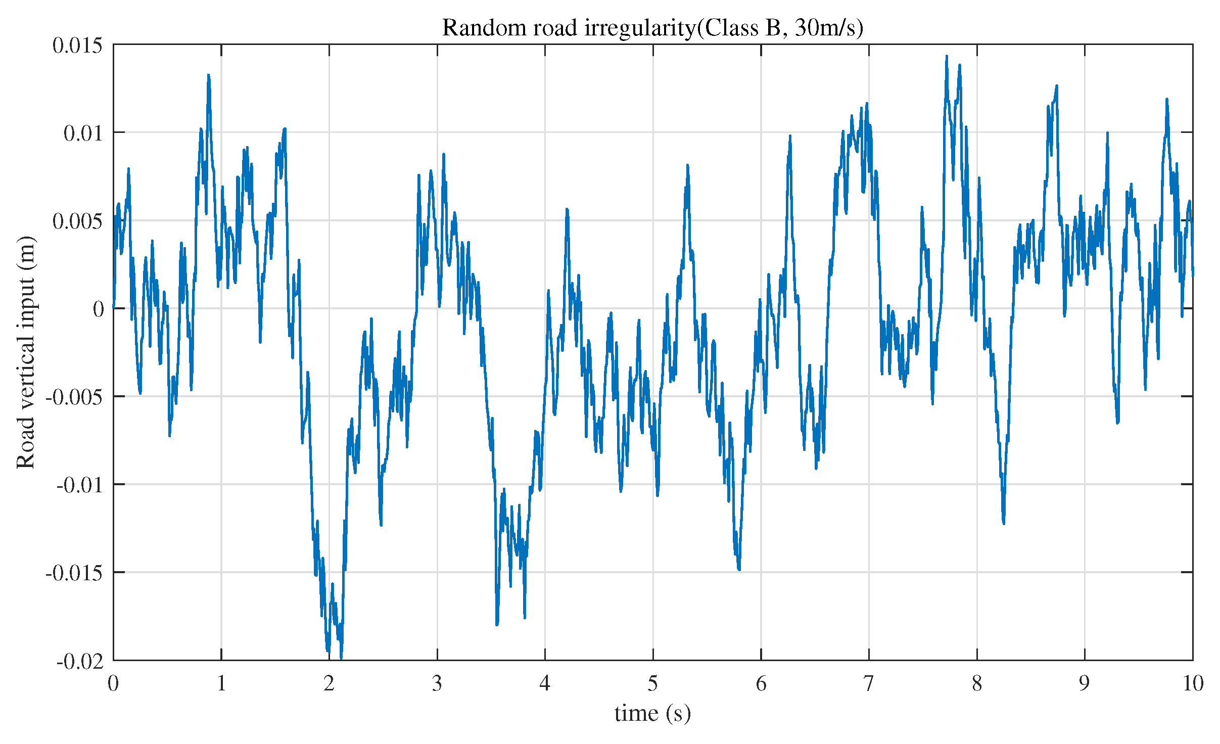
in which z r ( t ) is the road vertical displacement, V is the vehicle forward speed, and w ( t ) denotes the unit white noise with a covariance of 1 m 2 /s. In this paper, a quarter car suspension sunning on good road conditions is focused upon. Road classes A and B are selected, and the vehicle speeds are 20 m/s and 30 m/s. The road displacement input with class B road at 30 m/s is shown in Figure 4. This road displacement will be used as input for the optimization of the passive part parameters and the numerical simulation of the semi-active ISD suspension.

4.2. Optimization Objectives and Optimization Methods

Although ride comfort is the optimization goal, a balanced performance of ride comfort, road-holding, and suspension technological limitations is considered during the optimization. Parameters of the passive part in the ISD suspension will be optimized using PSO, taking the ride comfort, road-holding, and suspension technological limitations into account. The PSO algorithm, simulating the predatory behavior of a flock of birds, is a type of evolutionary algorithm [33]. PSO has the advantages of fast search speed and high accuracy. It is suitable for global parameter optimization.
The optimization goal function is chosen as follows, where the road input is taken as Figure 4.
Y = ρ 1 J A S M J A S M * + ρ 2 J T D L J T D L * + ρ 3 J S D J S D * s . t : L B b 1 , c 1 , b 2 , c 2 , k 2 U B
where ρ i is a weighting factor between ride comfort, road-holding, and suspension technological limitations. Since the main consideration of this paper is ride comfort, the values of ρ 1 , ρ 2 , and ρ 3 are 0.5, 0.25, and 0.25, respectively. J T D L * , J S D * , and J A S M * denote the RMS of sprung acceleration, RMS of tire dynamic load, and RMS of suspension deflection obtained from the traditional suspension under random road input, respectively. The J T D L , J S D , and J A S M values are the simulation result from the proposed suspension in this paper. The parameters of the mechanical elements b 1 , c 1 , k 2 , c 2 , and b 2 in Figure 3 are the quantities to be optimized.
In order to make the optimized parameters of each component feasible, upper and lower limits are therefore set for each component. x i represents the parameters of the component, which should be located between the lower limit L B and the upper limit U B . Considering the parameters of conventional suspensions, the range of individual component parameters is shown in Table 3.
In the PSO algorithm, each particle’s own state is described by a set of position and velocity vectors, which represent the feasible solution to the problem and its direction of motion in the search space [34]. The velocity and position update equations of the particle are given in the following equations:
v i ( t + 1 ) = W v i ( t ) + c I ( p i x i ( t ) ) R 1 + c I I ( g x i ( t ) ) R 2 x i ( t + 1 ) = x i ( t ) + v i ( t + 1 )
where i denotes the ith particle, v i ( t ) denotes the speed of iteration to t, x i ( t ) denotes the current position of the particle, p i and g denote the personal best and the global best of the particle, W is the inertia factor, and c I and c I I are the cognitive and social coefficient, respectively, which usually take values of c I , c I I are 0.8 and 0.4, respectively. R 1 and R 2 are random numbers with values between 0 and 1.
The number of particles is chosen to be 200 and the maximum number of iterations is 200 to find the minimum value of the fitness function given by Equation (12). The parameters of each component obtained after iterative optimization in MATLAB are shown in Table 4. So far, the configuration of the passive part, as well as their parameter is constructed.

5. Performance Analysis and Discussion of Semi-Active ISD Suspensions

In this section, the simulation and performance analysis of the semi-active ISD suspension will be performed. The random road in Figure 4 is selected as the input of the suspension system, and the semi-active ISD suspension proposed is simulated and compared with the traditional passive suspension and the traditional semi-active suspension. First of all, the ideal Sky-hook inerter suspension will be realized by the semi-active method. The maximum and minimum damping coefficient of traditional semi-active suspension are 300 and 2500, respectively. The damping coefficient of traditional passive suspension is 2200. The other parameters are the same as those of the suspension studied in this paper.
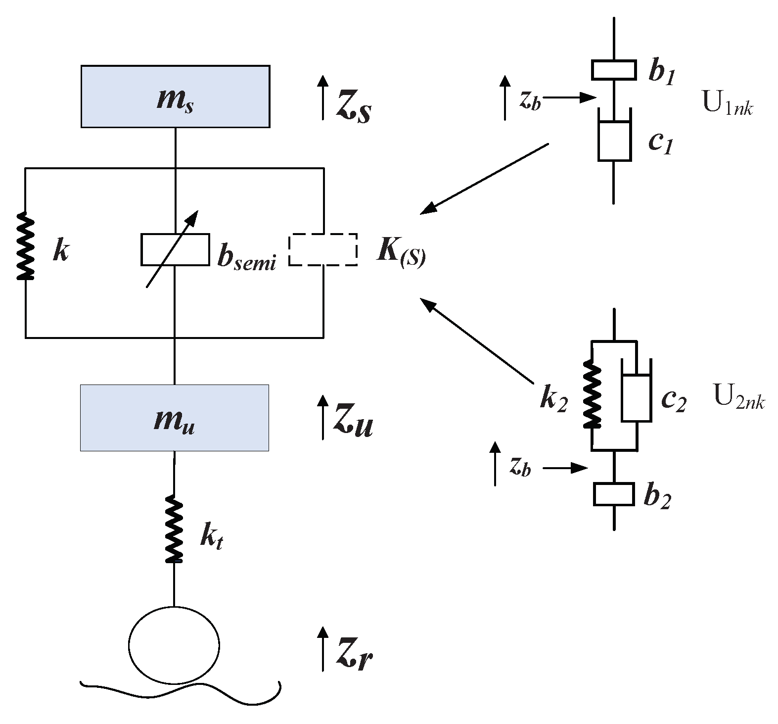
In this figure, the K ( s ) of the passive part will be replaced by the U 1 nk and U 2 nk mechanical networks, respectively, for the purpose of obtaining the first-order and second-order suspensions.

5.1. Semi-Active Realization of the Ideal Sky-Hook Inerter

The suspension is equipped with a semi-active inerter as shown in Figure 5, whose first-order and second-order suspension dynamics equations are given in the following equation:
z ¨ s m s + k ( z s z u ) + b semi ( z ¨ s z ¨ u ) + U 1 n k = 0 z ¨ u m u + k t ( z u z r ) k ( z s z u ) b semi ( z ¨ s z ¨ u ) U 2 n k = 0 U 1 n k = b 1 ( z ¨ s z ¨ b ) = c 1 ( z ˙ b z ˙ u ) U 2 n k = b 2 ( z ¨ b z ¨ u ) = c 2 ( z ˙ s z ˙ b ) + k 2 ( z s z b )
where b s k y is the inertance of the semi-active inerter, and U ink represents the forces transmitted by the first-order and second-order mechanical networks to the suspension system, i = 1 , 2 .
The inerter is in proportion to the relative acceleration of the two ends. In this case, the force of the Sky-hook inertance is then in proportion to the acceleration of the sprung mass, as the acceleration of the sky is zero. Therefore, the Sky-hook inerter can improve the ride comfort of the vehicle by the force that the Sky-hook inerter produces. The force conducted by the ideal Sky-hook inerter in Figure 1 is F = b s k y z ¨ s . The force conducted by the semi-active inerter in Figure 5 is F semi = b semi ( z ¨ s z ¨ u ) .
In order to make the semi-active suspension has the similar performance as the ideal Sky-hook inerter suspension, set F semi = F , where:
b semi = b s k y z ¨ s ( z ¨ s z ¨ u )
Similar to the Sky-hook damping control algorithm, for the Sky-hook inerter control algorithm, ON–OFF control and continuous control can be introduced according to the adjustable inertance of the semi-active inerter.
ON-OFF control:
b semi = b max , if z ¨ s ( z ¨ s z ¨ u ) 0 b min , if z ¨ s ( z ¨ s z ¨ u ) < 0
Continuous control:
b semi = b min b s k y z ¨ s z ¨ s z ¨ u b max , if z ¨ s ( z ¨ s z ¨ u ) 0 b min , if z ¨ s ( z ¨ s z ¨ u ) < 0
In order to make the force produced by the semi-active inerter equal to the one produced by the ideal Sky-hook inerter, take b max = b s k y ; in ideal conditions, b min = 0 .

5.2. Suspension Performance Analysis

With two road classes and two velocities, the ISD suspension system is simulated using both ON–OFF control and continuous control, and the simulation time is chosen to be 20 s.
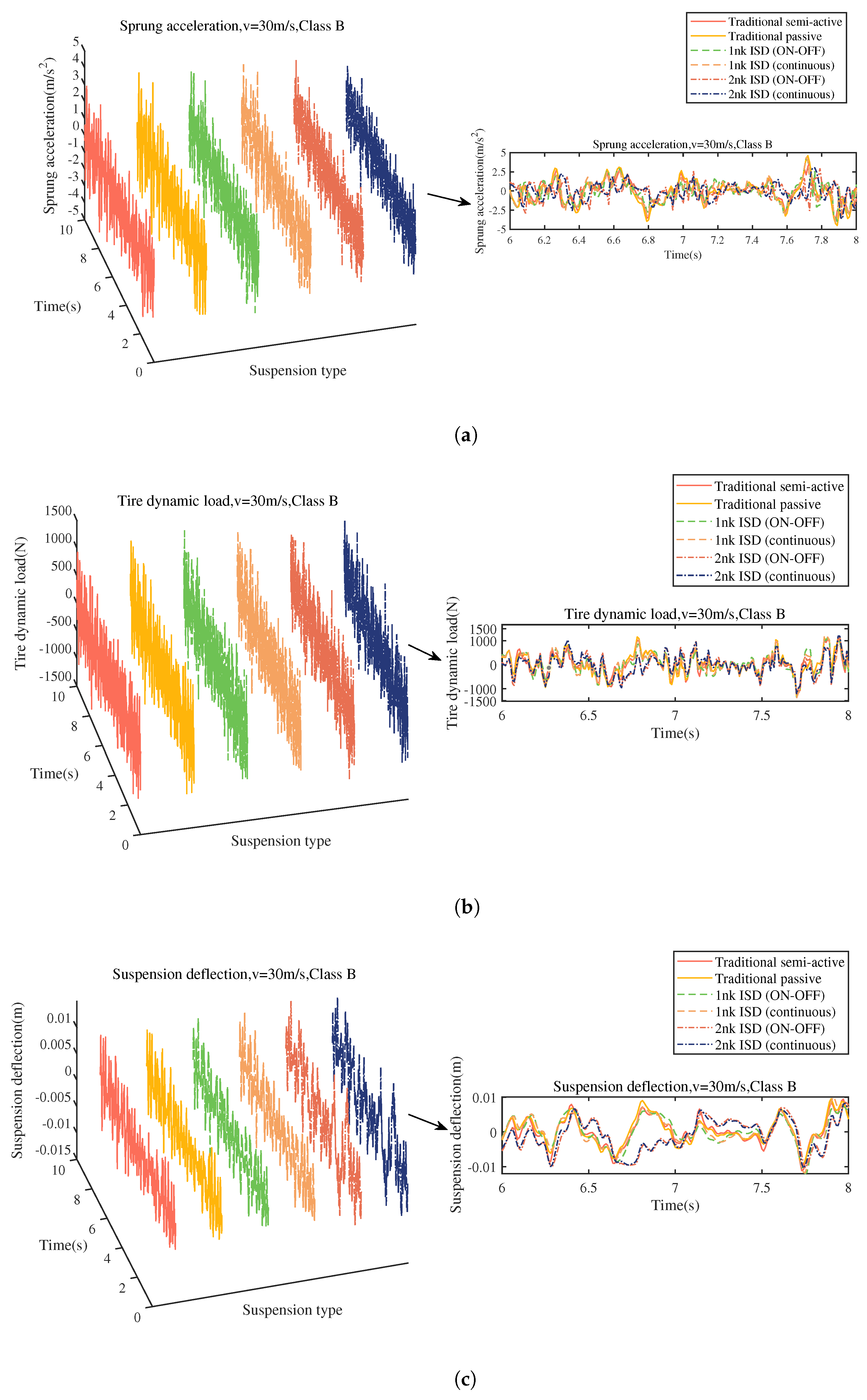
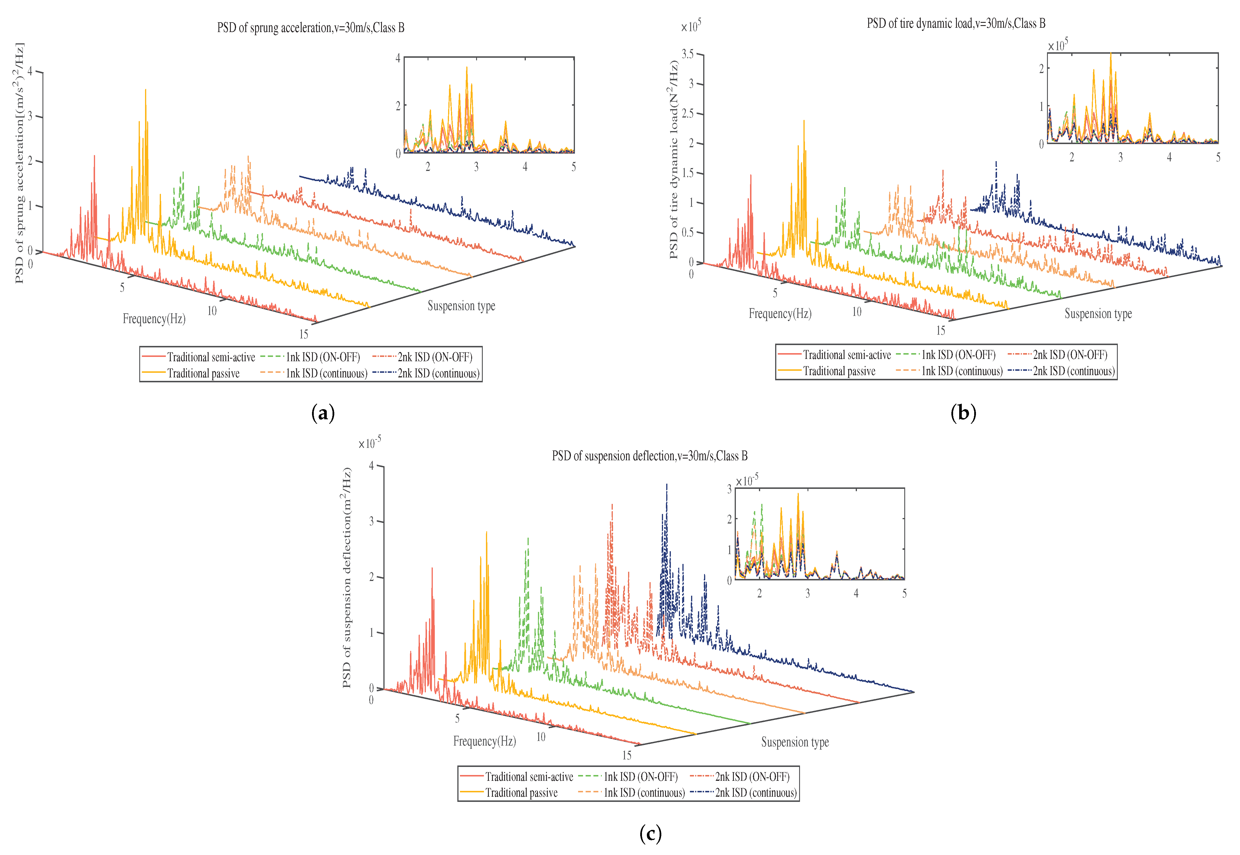
The RMS values of the performance are shown in Table 5, and the performance improvement rate of semi-active ISD suspension compared to traditional suspension is shown in Table 6. Taking the condition of class B road at 30 m/s for example, the system performance of different suspensions with time is shown in Figure 6. Figure 7 shows the performance curves in the frequency domain.
As can be seen from Table 5 and Table 6, the RMS value of sprung acceleration in Table 5 is the main performance index to the ride comfort as shown in Table 6. The tire dynamic load reflects the road-holding in Table 6. Compared to the traditional passive suspension, the ride comfort from the first-order ON–OFF and Continuous ISD suspensions improves around 19% on the Class A road and 13% on the Class B road, while there is also a slight advantage compared to the traditional semi-active suspension. On the other hand, the ride comfort from the second-order ON-OFF and Continuous ISD suspension, compared to the traditional passive suspension, reduced about 45% on the Class A road and 33% on the Class B road, respectively. The performance is also much better than the traditional semi-active suspension. In addition, the semi-active ISD suspension proposed in this paper benefits the road-holding as well; the tire dynamic loads are smaller than the traditional passive suspension; and the improvements are over 10% with first-order suspensions and 20% for second-order suspensions on the Class A road. On the Class B road, improvement depends on different orders and control methods, which are about 1%, 4%, 7%, and 11%. The road-holding is about the same level as the traditional semi-active suspension. In both classes of roads, the velocities contribute little influence to the ride comfort and road-holding performance. Furthermore, for the suspension deflection, the first-order ISD suspension is the same as the traditional one, while the second-order ISD suspension needs a little more space, which is in an acceptable range.
The simulated performances for the traditional and semi-active ISD suspensions on the class B road at 30 m/s are shown in Figure 6.
It can be seen in Figure 6a that the sprung acceleration curve of the traditional passive suspension has the largest maximum peak to peak value, followed by the traditional semi-active suspension. When the first-order semi-active ISD suspension system proposed in this paper chooses ON–OFF control, its dynamic response of the sprung acceleration will have a jitter problem during the direction reversing, which is similar to the traditional ON–OFF type of semi-active suspension. It is caused by the fact that the ON–OFF control can only switch the inertance. Moreover, ON–OFF control of the inertance may also destroy control elements such as the control valve of the semi-active inerter. The curves of the second-order semi-active ISD suspension have a lower maximum peak to peak value than the traditional suspensions and first-order ones, in which the jitter problem still goes with the ON–OFF control. Thus, the second-order semi-active ISD suspension with continuous control performs the best. In Figure 6b,c, the dynamic tire load and suspension deflection and the response curves of first-order and second-order semi-active ISD suspensions are consistent with the traditional ones. However, in the suspension deflection curve, the second-order semi-active ISD suspensions show the largest maximum peak to peak value. It can also be seen by the RMS value in the Table 5, which means that the second-order semi-active ISD suspensions need more space in the design.
From Figure 7a, it can be seen that the system responses excited by the road input are mainly in the frequency band of 1–5 Hz; the semi-active ISD suspension systems proposed in this paper have much lower PSD amplitude of the sprung acceleration compared to the traditional ones (passive, semi-active), and in the frequency band higher than 5 Hz, PSDs of the first-order, second-order semi-active ISD and traditional suspension are roughly the same. For the PSD of tire dynamic load in Figure 7b, it can be seen that the first-order and second-order semi-active ISD suspensions can significantly reduce the tire dynamic load in the resonance frequency band compared with traditional suspension, which enhances the safety of car driving. The second-order semi-active ISD suspension produces a little deterioration in the frequency band of 0–1 Hz. In addition, the first-order semi-active ISD suspension with ON–OFF control has a partial deterioration in the middle frequency band of 6–10 Hz. In Figure 7c, the body resonance frequency of suspension deflection in the second-order semi-active ISD suspension system is mainly concentrated between the 0 Hz and 1 Hz band compared with the traditional and first-order semi-active ISD suspensions, while the PSD of the latter two in the full frequency band have the same curve trend. It means that the second-order semi-active ISD suspension system has the lowerest resonance frequency and broadest frequency band for vibration attenuation. It can be shown by our simulation results that the semi-active ISD suspension proposed in this paper can effectively improve the ride comfort of the vehicle without reducing the road-holding of the vehicle. Notably, the second-order semi-active ISD suspension system shows a better performance than the first-order one.

6. Conclusions

In order to improve the ride comfort of the vehicle, this paper focuses on the design of a semi-active ISD suspension. Firstly, the first and second order passive structures of the semi-active ISD suspension are obtained by designing the positive real controller. Secondly, the semi-active inerter is used to further improve the ride comfort by the superiority of the inerter. By simulating the semi-active ISD suspension for a quarter vehicle, the following conclusions can be drawn:
  • The network synthesis approach is implemented for the optimization of the suspension construction. The suspension can be realized physically by the network synthesis method, which is more targeted with suspension performance than the traditional structure method.
  • The parameters of the obtained ideal Sky-hook ISD suspension are optimized using the PSO algorithm, and the performance of the obtained suspension structure can make further improvements to ride comfort while ensuring that the other performance does not deteriorate.
  • Both the first-order and second-order semi-active ISD suspensions proposed in this paper can effectively suppress the sprung acceleration in the low frequency band, which improves the ride comfort of the vehicle. The second-order semi-active ISD suspensions show better overall performance in both time and frequency domain.

Author Contributions

Conceptualization, Y.L. and S.H.; writing—original draft preparation, Y.L. and S.H.; writing—editing, Y.L. and S.H.; writing—review, J.X. and W.W. All authors have read and agreed to the published version of the manuscript.

Funding

This research was supported by the Science and Technology Program of Science and Technology Department of Yunnan Province under Grant 202001AU070032.

Data Availability Statement

Not applicable.

Conflicts of Interest

The authors declare no conflict of interest.

References

  1. Ghazaly, N.M.; Moaaz, A.O. The future development and analysis of vehicle active suspension system. Iosr J. Mech. Civ. Eng. 2014, 11, 19–25. [Google Scholar] [CrossRef]
  2. Savaresi, S.M.; Poussot-Vassal, C. Semi-Active Suspension Technologies and Models. In Active Suspension Technologies and Models; Elsevier: Oxford, UK, 2010; pp. 1–13. [Google Scholar]
  3. Priyandoko, G.; Mailah, M.; Jamaluddin, H. Direct voltage control of magnetorheological damper for vehicle suspensions. Smart Mater. Struct. 2013, 22, 105016. [Google Scholar]
  4. Chen, M.Z.Q.; Hu, Y.; Li, C.; Chen, G. Performance benefits of using inerter in semiactive suspensions. IEEE Trans. Control Syst. Technol. 2014, 23, 1571–1577. [Google Scholar] [CrossRef]
  5. Priyandoko, G.; Mailah, M.; Jamaluddin, H. Vehicle active suspension system using skyhook adaptive neuro active force control. Mech. Syst. Signal Proc. 2009, 23, 855–868. [Google Scholar] [CrossRef]
  6. Bitaraf, M.; Ozbulut, O.E.; Hurlebaus, S.; Barroso, L. Application of semi-active control strategies for seismic protection of buildings with MR dampers. Eng. Struct. 2010, 32, 3040–3047. [Google Scholar] [CrossRef]
  7. Yoon, D.S.; Kim, G.W.; Choi, S.B. Response time of magnetorheological dampers to current inputs in a semi-active suspension system: Modeling, control and sensitivity analysis. Mech. Syst. Signal Process. 2021, 146, 106999. [Google Scholar] [CrossRef]
  8. Pei, P.; Peng, Y.; Qiu, C. An improved semi-active structural control combining optimized fuzzy controller with inverse modeling technique of MR damper. Struct. Multidiscip. Optim. 2022, 55, 272. [Google Scholar] [CrossRef]
  9. Alonso, A.; Gimenez, J.G.; Nieto, J.; Vinolas, J. Air suspension characterisation and effectiveness of a variable area orifice. Veh. Syst. Dyn. 2010, 48, 271–286. [Google Scholar] [CrossRef]
  10. Ning, D.; Christie, M.D.; Sun, S.; Du, H.; Li, W.; Wang, Y. A controllable mechanical motion rectifier-based semi-active magnetorheological inerter for vibration control. Smart Mater. Struct. 2020, 29, 114005. [Google Scholar] [CrossRef]
  11. Chen, M.Z.Q.; Hu, Y. Semi-active Inerter and Adaptive Tuned Vibration Absorber. In Inerter and Its Application in Vibration Control Systems; Springer: Singapore, 2019; pp. 103–119. [Google Scholar]
  12. Smith, M.C. The inerter: A retrospective. Annu. Rev. Control Robot. Auton. Syst. 2020, 3, 361–391. [Google Scholar] [CrossRef]
  13. Smith, M.C. Synthesis of mechanical networks: The inerter. IEEE Trans. Autom. Control 2002, 47, 1648–1662. [Google Scholar] [CrossRef] [Green Version]
  14. Wang, K.; Chen, M.Z.Q. Passive mechanical realizations of bicubic impedances with no more than five elements for inerter-based control design. J. Frankl. Inst. 2021, 358, 5353–5385. [Google Scholar] [CrossRef]
  15. Papageorgiou, C.; Smith, M.C. Positive real synthesis using matrix inequalities for mechanical networks: Application to vehicle suspension. IEEE Trans. Control Syst. Technol. 2006, 14, 423–435. [Google Scholar] [CrossRef] [Green Version]
  16. Hu, Y.; Chen, M.Z.Q. Low-complexity passive vehicle suspension design based on element-number-restricted networks and low-order admittance networks. J. Dyn. Syst. Meas. Control 2018, 140, 101014. [Google Scholar] [CrossRef]
  17. Wang, K.; Chen, M.Z.Q.; Hu, Y. Synthesis of biquadratic impedances with at most four passive elements. J. Frankl. Inst. 2014, 351, 1251–1267. [Google Scholar] [CrossRef] [Green Version]
  18. Chen, L.; Liu, C.; Liu, W.; Nie, J.; Shen, Y.; Chen, G. Network synthesis and parameter optimization for vehicle suspension with inerter. Adv. Mech. Eng. 2016, 9. [Google Scholar] [CrossRef]
  19. Jiang, J.Z.; Smith, M.C. Regular positive-real functions and five-element network synthesis for electrical and mechanical networks. IEEE Trans. Autom. Control 2010, 56, 1275–1290. [Google Scholar] [CrossRef]
  20. Chen, M.Z.Q.; Li, Z.; Wang, H. Seismic response mitigation of a wind turbine via inerter-based structural control. Bull. Earthq. Eng. 2021, 21, 1361–1388. [Google Scholar] [CrossRef]
  21. He, H.; Li, Y.; Jiang, J.Z.; Burrow, S.; Neild, S.; Conn, A. Using an inerter to enhance an active-passive-combined vehicle suspension system. Int. J. Mech. Sci. 2021, 204, 106535. [Google Scholar] [CrossRef]
  22. Hu, Y.; Wang, K.; Chen, M.Z. Inerter-based semi-active suspensions with low-order mechanical admittance via network synthesis. Trans. Inst. Meas. Control 2018, 40, 4233–4245. [Google Scholar] [CrossRef]
  23. Tseng, H.E.; Hrovat, D. State of the art survey: Active and semi-active suspension control. Veh. Syst. Dyn. 2015, 57, 1034–1062. [Google Scholar] [CrossRef]
  24. Hu, Y.; Chen, M.Z.Q.; Xu, S.; Liu, Y. Semiactive Inerter and Its Application in Adaptive Tuned Vibration Absorbers. IEEE Trans. Control Syst. Technol. 2016, 25, 294–300. [Google Scholar] [CrossRef]
  25. Li, P.; Lam, J.; Cheung, K.C. Investigation on semi-active control of vehicle suspension using adaptive inerter. In Proceedings of the 21st International Congress on Sound and Vibration (ICSV 21), Beijing, China, 13–17 July 2014; pp. 3367–3374. [Google Scholar]
  26. Hu, Y.; Chen, M.Z.Q.; Sun, Y. Comfort-oriented vehicle suspension design with skyhook inerter configuration. J. Sound Vib. 2017, 405, 34–47. [Google Scholar] [CrossRef]
  27. Boyd, S.; El Ghaoui, L.; Feron, E.; Balakrishnan, V. Linear Matrix Inequalities in System and Control Theory; Society for Industrial and Applied Mathematics Philadelphia: Philadelphia, PA, USA, 1994. [Google Scholar]
  28. Smith, M.C.; Wang, F.C. Performance benefits in passive vehicle suspensions employing inerters. Veh. Syst. Dyn. 2004, 42, 235–257. [Google Scholar] [CrossRef] [Green Version]
  29. Katoch, S.; Chauhan, S.S.; Kumar, V. A review on genetic algorithm: Past, present, and future. Multimed. Tools Appl. 2021, 80, 8091–8126. [Google Scholar] [CrossRef] [PubMed]
  30. Kawanishi, M.; Ikuyama, Y. BMI optimization based on unimodal normal distribution crossover GA with relaxed LMI convex estimation. In Proceedings of the 2005, American Control Conference, Portland, OR, USA, 8–10 June 2005; pp. 2299–2304. [Google Scholar]
  31. Lofberg, J. YALMIP: A toolbox for modeling and optimization in MATLAB. In Proceedings of the 2004 IEEE International Conference on Robotics and Automation, Taipei, Taiwan, China, 2–4 September 2004; pp. 284–289. [Google Scholar]
  32. ISO 8608:2016; Mechanical Vibration–Road Surface Profiles–Reporting of Measured Data. ISO: Geneva, Switzerland, 2016. Available online: https://www.iso.org/standard/71202.html (accessed on 7 November 2022).
  33. Kennedy, J.; Eberhart, R. Particle swarm optimization. In Proceedings of the ICNN’95-International Conference on Neural Networks, Perth, WA, Australia, 27 November–1 December 1995; pp. 1942–1948. [Google Scholar]
  34. Marini, F.; Walczak, B. Particle swarm optimization (PSO). A tutorial. Chemom. Intell. Lab. Syst. 2015, 149, 153–165. [Google Scholar] [CrossRef]
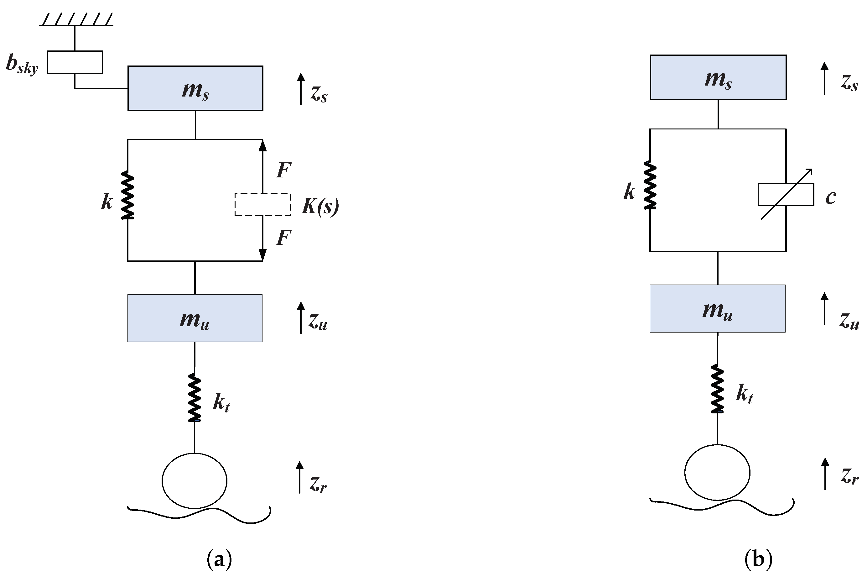
Figure 1. Quarter vehicle suspension model. (a) Semi-active ISD suspension. (b) Traditional semi-active suspension.
Actuators 12 00290 g001
Figure 2. Block diagram of robust positive real control model.
Actuators 12 00290 g002
Figure 3. Physical implementation of the K ( s ) . (a) First-order. (b) Second-order.
Actuators 12 00290 g003
Figure 4. Random road irregularity (Class B, 30 m/s).
Actuators 12 00290 g004
Figure 5. Semi-active quarter vehicle ISD suspension.
Actuators 12 00290 g005
Figure 6. Dynamic response for the suspension system. (a) Sprung acceleration. (b) Tire dynamic load. (c) Suspension deflection.
Actuators 12 00290 g006
Figure 7. PSD of the suspension system for performance evaluation. (a) PSD of sprung acceleration. (b) PSD of tire dynamic load. (c) PSD of suspension deflection.
Actuators 12 00290 g007
Table 1. Vehicle suspension parameter.
ParameterValue
Sprung mass m s ( k g ) 250
Unsprung mass m u (kg)35
Support spring stiffness k (N/m)80,000
Tire stiffness k t (N/m)150,000
Ideal Sky-hook inertance b s k y (kg)120
Table 2. Road classification.
Road Class G q ( n 0 ) ( 10 6 ) ( n 0 = 0.1 m 1 )
      A (very good)16
      B (good)64
      C (average)256
      D (poor)1024
      E (very poor)4096
Table 3. Range of optimization parameter.
Parameter VariableLower LimitUpper Limit
Inertance b 1 (kg)1001000
Damping coefficient c 1 (N · s/m)10007000
Inertance b 2 (kg)501000
Damping coefficient c 2 (N · s/m)5006000
Spring stiffness k 2 (N/m)500020,000
Table 4. Parameter optimization result.
ParameterOptimization Results
Inertance b 1 (kg)890.65
Damping coefficient c 1 (N · s/m)2542.12
Inertance b 2 (kg)996.13
Damping coefficient c 2 (N · s/m)2005.21
Spring stiffness k 2 (N/m)5002.92
Table 5. RMS value of vehicle performance under different vehicle condition.
ConditionsPerformanceTraditional SuspensionISD Suspension (1 nk)ISD Suspension (2 nk)
Index (RMS)PassiveSemi-ActiveON-OFFContinuousON–OFFContinuous
Sprung acceleration (m/s 2 )0.78730.68250.64210.63780.42020.4338
Class A, 20 m/sTire dynamic load (N)218.7408195.4778195.7847193.3658174.3653171.9115
Suspension deflection (m)0.00210.00190.00210.00200.00270.0027
Sprung acceleration (m/s 2 )0.95350.82810.76880.77210.52230.5306
Class A, 30 m/sTire dynamic load (N)365.1126338.2103361.4294349.0471337.0507323.6969
Suspension deflection (m)0.00330.00320.00340.00330.00420.0041
Sprung acceleration (m/s 2 )1.28581.13001.12861.10350.82760.8531
Class B, 20 m/sTire dynamic load (N)265.1425237.4449237.2606234.6618210.9755207.4685
Suspension deflection (m)0.00250.00240.00250.00240.00300.0029
Sprung acceleration (m/s 2 )1.55931.36791.35771.33731.02291.0399
Class B, 30 m/sTire dynamic load (N)443.2428410.1071435.5959424.2941409.5107391.4729
Suspension deflection (m)0.00390.00380.00390.00390.00470.0046
Table 6. Performance improvement rate of the semi-active ISD suspension compared to the traditional suspension.
VehiclePerformanceISD Suspension (1 nk)ISD Suspension (2 nk)
SpeedIndexON-OFFContinuousON-OFFContinuous
Class A, 20 m/sRide comfort18.4%18.9%46.6%44.9%
Road-holding10.5%11.6%20.3%21.4%
Class A, 30 m/sRide comfort19.4%19.1%45.2%44.4%
Road-holding10.5%11.5%20.4%21.8%
Class B, 20 m/sRide comfort12.2%14.2%35.6%33.7%
Road-holding1.1%4.4%7.7%11.3%
Class B, 30 m/sRide comfort13.1%14.2%34.4%33.3%
Road-holding1.8%4.3%7.6%11.7%
Disclaimer/Publisher’s Note: The statements, opinions and data contained in all publications are solely those of the individual author(s) and contributor(s) and not of MDPI and/or the editor(s). MDPI and/or the editor(s) disclaim responsibility for any injury to people or property resulting from any ideas, methods, instructions or products referred to in the content.