Abstract
An analytical dynamic model is presented for a spacecraft with multiple large flexible structures. Based on the partial differential equations (PDEs) of the motion of the solar panel and deployable arm, the governing equations of the main-body and deployable antenna and the boundary conditions at each end point are used to obtain the frequency and mode shapes of the system. Then, the ordinary differential equations (ODEs) of the system can be obtained from the orthogonality relations and mode shape. The influence of the deployable antenna on the frequencies and mode shapes of the spacecraft is investigated. The frequency veering and mode interchanged phenomenon are observed with the variation of the diameter of the deployable antenna. Using the ODEs, the dynamic responses of the spacecraft are calculated to study the influence of the control torque on the attitude and position of the antenna in the attitude maneuver.
1. Introduction
With the rapid development of space communication technology, the new generation of satellites is required to be multi-functional and have a long life and high performance. Thus the required spacecraft often need installation of solar wings and deployable antennas.
A large deployable antenna structure is widely used to increase the gain of the space-borne antenna [1]. In 2000, the United States successfully launched the commercial communications satellite Thuraya with a 12.25-m aperture and 55 kg mass [2]. Subsequently, the two Thuraya communication satellites launched in 2003 and 2008 used the same deployable antenna [3]. Thomson [4] found that increasing the antenna size within a certain range does not change its structure and that the unit mass does not increase proportionally but shows a significant downward trend. In the design of the spacecraft attitude control, the main source of radiation force is direct exposure to the sun. Bohling et al. [5] studied the torques produced by the radiation forces on the spacecraft. Solar heating of spacecraft causes antennas far from the sun to bend in the direction of satellite rotation, while antennas near the sun bend in the opposite direction of satellite rotation. Palmerini and Sgubini [6] enhanced the stability of the gravity gradient by adjusting the solar reflector and absorption surface.
For the large-scale space-borne annular truss antenna system, the main components include a two-stage flexible deployable arm, deployable annular truss, wire reflection network, and tension network [4]. For such a complex circular truss antenna structure, the use of finite element software is a practical and effective way to analyze its dynamics [7,8,9,10,11,12,13,14]. Mobre et al. [14] established a finite element model for a deployable antenna structure consisting of two flexible deployable arms and an annular truss; the model obtained the first three natural frequencies and modal shapes of the antenna structure, including pitching, rolling of the annular trusses, and bending vibration of the deployable arms. Based on the finite element method (FEM), Chodimella et al. [13] found that the thermal strain on the antenna can cause great disturbance to the shape, so it is necessary to add sun-visor and multi-layer insulating material to reduce the thermal disturbance amplitude on the system.
Due to the large and flexible structure of spacecraft, the corresponding system modeling, identification, and control problems have become increasingly complex. Based on experimental methods [15,16,17,18], Sabatini et al. [16] used a vibration data acquisition method based on image technology to simulate highly flexible solar panels using aluminum sheets for identifying the vibration modes and characteristic frequencies of spacecraft’s flexible structures. Ivanov et al. [17] studied the vibration testing methods of spacecraft with elastic elements such as sensors based on direct inverse Piezoelectricity, sensors and accelerometers based on fiber grating, etc. Wang et al. [18] studied centralized vibration control for measuring flexible dynamic behavior using optical cameras instead of attaching intelligent sensors or actuators nearby to separate the vibration of flexible attachments from disturbances. Angeletti et al. [15], based on the design of spacecraft vibration control structure, carried out numerical simulation through a nonlinear orbit simulator and compared the results with those obtained using a baseline PID controller, finding that robust control has better performance.
Although the FEM and experimental methods can provide an effective approach for the dynamic analysis of complex high-dimensional nonlinear systems, it is necessary to understand and extract the dynamic behavior of the system of the finite element model based on tens of thousands of degrees of freedom. Relatively speaking, analytical methods based on analytical or semi-analytical solutions are helpful to grasp the dynamic characteristics of the system and to explore the global dynamic phenomena of the system.
Using the mode functions to describe the elastic deformation of flexible structures can greatly reduce the degree of freedom of the established system dynamics model, which is very suitable for the design of structural vibration controllers. Spacecraft with a very rigid bus have appendages that demonstrate flexible behavior; in these cases, it is convenient to use the cantilever and other constrained boundary modes to obtain the assumed modes. Therefore, the assumed mode method (AMM) is most widely used in the dynamic modeling of flexible spacecraft for which rigid body platforms are dominant [19,20,21,22,23].
For flexible spacecraft in which the inertia of the rigid body platform does not dominate, the assumed mode can no longer accurately describe the real deformation of the flexible component. In this regard, the dynamic model of large flexible spacecraft established using the global mode is more accurate, because the global mode can truly reflect the elastic vibration of each flexible component in the spacecraft and the motion of the rigid body platform. Based on GMM, Hablani [24] conducted a comprehensive study of the dynamic characteristics and control of flexible spacecraft. Hablani [25] pointed out that, in comparison with the AMM, the dynamic model has its accuracy determined by the inertial ratio of the spacecraft system. Because the global mode contains the modal information of the entire system, selecting a small number of global modes can better describe the motion of the system [26], which makes the global mode very suitable for multiple large flexible structures.
In summary, for large flexible spacecraft, compared with the AMM, the dynamic model established by the global mode has lower degrees of freedom and higher accuracy. However, the global mode is not as direct as the assumed mode, and how to accurately obtain the global mode of the system becomes the key point. Based on the development of the GMM, Wei and Cao applied it to the dynamic modeling and analysis of flexible spacecraft with jointed solar wings [27,28], flexible space manipulators [29], and multi-beam jointed structures [30,31].
Based on the methodology in [28,29,31], a rigid-flexible coupled global modal analysis method for the vibration of the rigid-body platform and flexible appendages (solar wing and deployable antenna) of spacecraft is developed, and the influence of the deployable antenna on the frequencies and mode shapes of the spacecraft is investigated. The frequency veering and mode interchanged phenomenon is observed with the variation of the diameter of the deployable antenna. The explicit orthogonal relationship between the body and the deployable antenna is described, and the global modal shape and orthogonality are used to derive a set of ODEs governing the motion of the system; the dynamic responses of the spacecraft are calculated to investigate the influence of the control torque on the attitude and position of the antenna in the attitude maneuver.
2. Dynamic Modeling for a Spacecraft with Multiple Large Flexible Structures
2.1. Governing Equations of Motion
Consider the planar motion of a spacecraft that consists of a main-body, two solar arrays, a deployable arm, and deployable antenna, as shown in Figure 1. The solar array and deployable arm are modeled as a Euler–Bernoulli beam. The main-body is assumed to be a rigid body. Because the elastic deformation of the deployable antenna is much smaller than that of the solar wing and the deployable arm, the deployable antenna is simplified as a rigid disk.
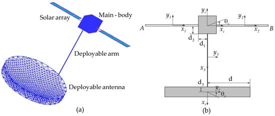
Figure 1.
Spacecraft with multiple flexible structures: (a) spatial motion model and (b) planar motion model.
The moment of inertia of the solar array is I1, elastic modulus is E1, length is L1, and mass per unit length is . Similarly, the mass per unit length, elastic modulus, moment of inertia, and length of the deployable arm are denoted by , E2, I2, and L2, respectively. mc and Jc are the mass and moment of inertia of the main-body, respectively. mr and Jr are the mass and moment of inertia of the deployable antenna, respectively. d is used to describe the radius of the deployable antenna. Let and be the coordinates of the main-body and deployable antenna, respectively. Let , , and be the coordinates of the left solar array, right solar array, and deployable arm, respectively. θc is used to describe the rotational displacement of the main-body, yc is the translational displacements in the vertical directions, and xc is the translational displacements in the horizontal direction of the main-body. yr and θr are the translational displacement in the horizontal direction and rotational displacement of the deployable antenna, respectively.
The Euler–Bernoulli beam theory suggests the motion equations of the solar arrays can be expressed as
where a prime represents partial differentiation with respect to , and an overdot represents partial differentiation with regard to time . and are the displacements of the left and right solar arrays, respectively.
Similarly, the motion equation of the deployable arm is expressed as
where is the displacement of the deployable arm.
Using the matching conditions, as illustrated in Figure 2a, the motion equations of the main-body for the translation in the horizontal and vertical directions are
where and .
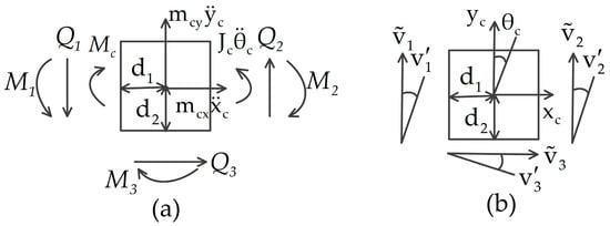
Figure 2.
Schematic of the (a) natural and (b) geometrical matching conditions of the main-body: (a) , and are the shear forces acting on the main-body, , , and ; , and are the bending moment acting on the main-body, , , ; (b) , , , , , and .
The motion equation of the main-body for the rotation is
where is the distance from the center of the main-body to the solar array, and is the distance from the center of the deployable antenna to the deployable arm. The attitude control torque acting on the main-body is denoted by .
As shown in Figure 3a, using the natural matching conditions, the motion equations of the deployable antenna for the translation and rotation are
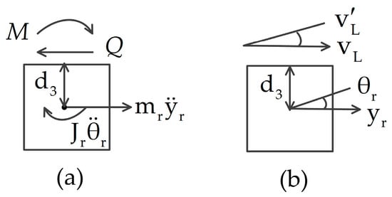
Figure 3.
Schematic of the (a) natural and (b) geometrical matching conditions of deployable antenna: (a) is the shear force acting on deployable antenna, ; is the bending moment acting on deployable antenna, ; (b) .
Next, the boundary condition of the spacecraft is analyzed. The geometric matching conditions of the main-body are illustrated in Figure 2b.
The geometric matching conditions of the deployable antenna are depicted in Figure 3b.
The and of the solar arrays are the free ends of the cantilever beam, with zero bending moment and shear force.
2.2. Natural Frequencies and Global Mode Shapes
In order to obtain a low-dimensional dynamic model, it is necessary to study the eigenvalue problem of the system to obtain the global mode shapes. It is assumed that the displacements of the spacecraft are separable in space and time. Where is an unknown constant relating to the system’s natural frequency, let
Integrating Equation (11) into Equations (1)–(7) without external force yields
The main-body geometric matching conditions are simplified to
The geometric matching conditions of the deployable antenna are reduced to
The boundary conditions at and become
The solutions of Equations (12) and (13) are
where and . Let
Substituting Equation (22) into Equations (19)–(21), and then determining the main-body and deployable antenna using Equations (14)–(18), the following characteristic equation can be obtained:
where the matrix .
Let . is the s-th natural frequency, and is the s-th global mode shapes for the system.
2.3. Orthogonality
and represent the global mode shapes associated with the two unique eigenvalues and .
By Equations (12)–(18), one has
Then, multiply Equation (27) by and ; for the two solar arrays, integrate the resulting equations across the domain , respectively; multiply Equation (28) by ; integrate the resulting equations over the domain for the deployable arm; and add the resulting equations to obtain
Multiply Equations (29)–(33) by , , , , and , respectively, and then sum the resulting equations to obtain
Using the boundary and matching conditions in Equations (19)–(21), adding Equation (35), and integrating Equation (34) by parts yields
Substituting Equation (36) into the left-hand side of Equation (34) yields
Exchanging the superscripts and in Equation (37) yields
Subtracting Equation (37) from Equation (38) yields
The first orthogonality relation can be derived from Equation (39).
where is s-th modal mass and is the Kronecker delta. The second orthogonality relation can be calculated using Equations (37) and (40).
where is modal stiffness.
2.4. Dynamic Model with Multi-DOF
By using the global mode shapes obtained by characteristic Equation (25), the displacements of the flexible spacecraft can be written as
The sr-th modal coordinate of the system is .
Substituting Equation (42) into Equations (1)–(7) yields
Multiply Equation (43) by and ; for the two solar arrays, integrate the resulting equations across the domain , respectively; multiply Equation (44) by ; integrate the resulting equations over the domain for the deployable arm; multiply Equations (45)–(49) by , , , , and , respectively; apply the orthogonality relations in Equations (40) and (41); and add all of the resulting equations and Equations (8)–(10) of the boundary condition. We then have
where and are the modal stiffness and modal mass of s-th, respectively.
3. Results and Discussion
In this section, the first eight mode shapes of the spacecraft with large flexible structures are provided. Then, the influence of the deployable antenna on the natural frequencies and global mode shapes of the flexible spacecraft is discussed and then compared with the influence as obtained from the finite element software ANSYS. Finally, the dynamic responses of the spacecraft under the attitude control torque are performed. Table 1 lists the physical parameters of the spacecraft.

Table 1.
The parameters of the spacecraft.
For the finite element model, the solar arrays, the main-body, the deployable arm, and the deployable antenna are modeled by the BEAM 188 element, the SOLID 45 element, the PIPE 16 element, and the SOLID 45 element, respectively. The flexible spacecraft is divided into 12,892 elements. Table 2 shows that the first eight natural frequencies and global mode shape obtained from the proposed model were in excellent agreement with those obtained from ANSYS, such that the largest difference in natural frequencies was only 3.83%. In addition, the first eight mode shapes obtained by the proposed model were exactly the same as those from the model in ANSYS. All the above findings prove the validity of the dynamic model proposed here.

Table 2.
The lowest eight natural frequencies of the bridge system .
3.1. Mode Analysis
Figure 4 depicts the first eight global mode shapes of the flexible spacecraft. As illustrated in the figure, since the flexible spacecraft is a symmetrical T-shaped configuration, its global mode shapes show the characteristics of symmetry and antisymmetry. In the first mode shape, the translational displacement of the main-body in the vertical direction and the left and right solar arrays are the same. In the second mode shape, the main-body undergoes rotational displacement, the deployable antenna undergoes translational displacement in the horizontal direction and rotational displacement, and the left and right solar arrays are opposite. In the third mode shape, the main-body shows significant rotational displacement, the deployable antenna exhibits a small degree of horizontal and rotational displacement, and the left and right solar arrays are opposite. In the fourth mode shape, the translational displacement of the main-body in the vertical direction and the left and right solar arrays are the same. In the fifth mode shape, the main-body shows significant rotational displacement, the deployable antenna undergoes translational displacement in the horizontal direction and rotational displacement, and the left and right solar arrays are opposite. In the sixth mode shape, the main-body shows significant rotational displacement, the deployable antenna exhibits a small degree of horizontal and rotational displacement, and the left and right solar arrays are opposite. In the seventh mode shape, the translational displacement of main-body in the vertical direction and the left and right solar arrays are the same. In the eighth mode shape, the main-body shows significant rotational displacement, the deployable antenna exhibits a small degree of horizontal and rotational displacement, and the left and right solar arrays are opposite.
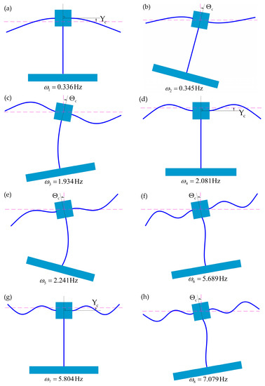
Figure 4.
The flexible spacecraft’s first to eighth global mode shapes (a–h).
The first, fourth, and seventh mode shapes are symmetric, and the rest of the mode shapes are antisymmetric. The symmetrical mode shapes show the characteristic of local deformation, where only the solar wing is deformed. The antisymmetric mode shows global deformation, where the solar arrays and the deployable arm are both deformed.
In order to investigate the influence of the deployable antenna on the spacecraft, the natural frequencies of the spacecraft are calculated when the deployable antenna diameter varies from 5 to 30 m, as shown in Figure 5. It can be clearly seen that as the antenna diameter increases, the mode exchange phenomenon occurs with the frequency veering phenomenon. At antenna diameters of 28 m, 7 m, and 14 m, the interchange of first mode and second mode, the interchange of third mode and fourth mode, and the interchange of sixth mode and seventh mode occur, respectively. From Figure 4 and Figure 5, it can be concluded that the mass and moment inertia of the antenna have a great influence on the natural frequency corresponding to the antisymmetric mode but almost no effect on the natural frequency corresponding to the symmetric mode. When the frequency veering phenomenon occurs, the symmetric and antisymmetric modes are interchanged with each other.
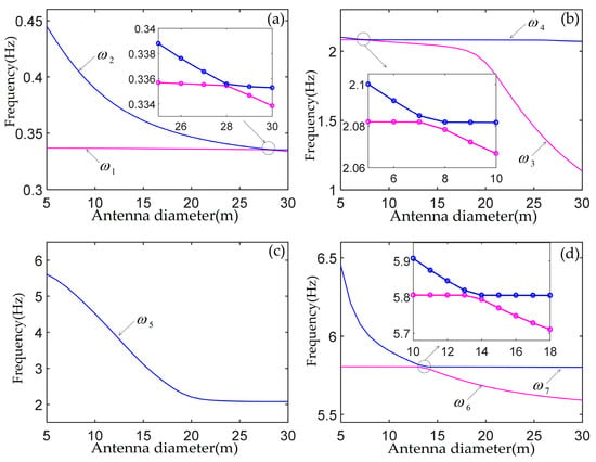
Figure 5.
The first seven natural frequencies versus the deployable antenna diameter: (a) the first and second frequencies, (b) the third and fourth frequencies, (c) the fifth frequencies, (d) the sixth and seventh frequencies.
3.2. Dynamic Responses
The vibration response of the spacecraft with solar arrays and deployable antenna in the attitude maneuver is investigated in this section. It is assumed that the attitude control torque is
where and are the period and amplitude of the attitude control torque, re-spectively. Figure 6 depicts the attitude control torque acting on the flexible spacecraft.
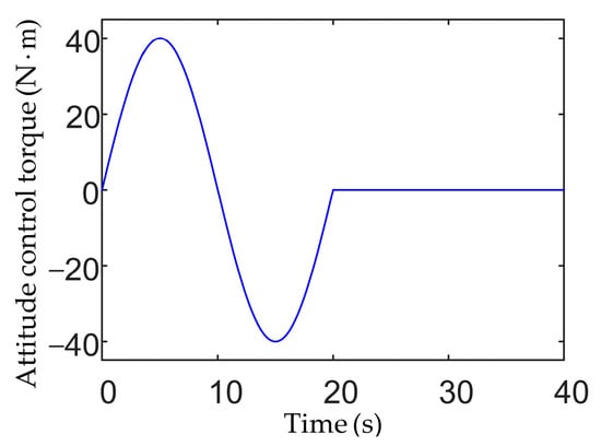
Figure 6.
Time history of attitude control torque.
It is clear from Figure 4 that the symmetrical modes cannot be excited by attitude control torque. Therefore, there is no translational vibration response of the main-body in the vertical direction. In this case, the deployable antenna mass and moment of inertia are 94.25 kg and 2356 (kg·m2), respectively. The first 10 modes are selected to calculate the vibration responses of the flexible spacecraft, as shown in Figure 7, Figure 8 and Figure 9.
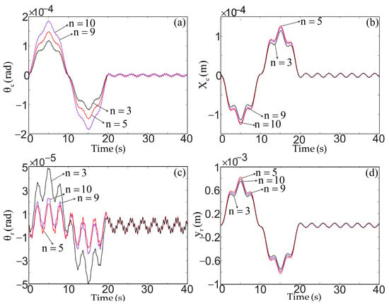
Figure 7.
Vibration response of the main-body (a) rotation and (b) translation in horizontal direction, and the deployable antenna (c) rotation and (d) translation in horizontal direction.
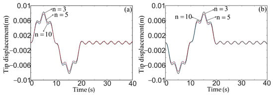
Figure 8.
Vibration response of the solar array tip: (a) left and (b) right.

Figure 9.
Vibration response of the deployable antenna: (a) second mode, (b) third mode, and (c) fifth mode.
Figure 7 demonstrates that the vibration amplitude of the main-body attitude is much larger than the vibration amplitude of the antenna attitude, and the vibration amplitude of the antenna in the horizontal direction is much greater than the vibration amplitude of the main-body in the horizontal direction. This indicates that the attitude control torque operating on the main-body has more influence on the horizontal translation of the antenna than on the attitude of the antenna. The rotational motion of the main-body and deployable antenna requires more degrees of freedom, and the number of degrees of freedom of its horizontal translation response has little impact on it. In addition, because the displacement of the second mode of the antenna cancels out the displacement of the third and fifth modes, as shown in Figure 9, the vibration response of the antenna appears different, as shown in Figure 7c. From Figure 8, since only the antisymmetric modes can be excited by the attitude control torque, the two solar arrays are deformed in the opposite direction.
4. Conclusions
A dynamic modeling approach has been described to obtain an analytical model for a spacecraft with large solar arrays and deployable antenna. The use of the natural frequencies, the global mode shapes, and their orthogonality relations results in fewer degrees of freedom for the decoupled analytical model of the flexible spacecraft, which is not only convenient for studying the system’s nonlinear dynamic behavior, but also suitable for vibration control of the spacecraft with multiple large flexible structures.
The flexible spacecraft has been investigated taking into consideration various sizes of the deployable antenna, and the dynamic responses of the spacecraft have been calculated in the attitude maneuver. Some conclusions are summarized as follows:
- (1)
- Since the flexible spacecraft is symmetrical, its global mode shapes show the characteristics of symmetry and antisymmetry. As the diameter of the deployable antenna increases, the frequency veering phenomenon occurs, and the symmetric and the antisymmetric modes are interchanged with each other.
- (2)
- When the control torque is applied on the main-body to maneuver the attitude of the spacecraft, its influence on the horizontal position of the deployable antenna is much greater than the effect on the attitude of the deployable antenna.
Author Contributions
Conceptualization, J.W.; methodology, J.W.; software, W.L. and J.L.; investigation, writing—original draft, J.W., W.L. and J.L; writing—review and editing, J.W., W.L. and T.Y.; visualization, W.L. and J.L.; supervision, J.W. and T.Y.; project administration, J.W. and T.Y. All authors have read and agreed to the published version of the manuscript.
Funding
This work was supported by the China Postdoctoral Science Foundation (Grant No. 2020M681578); the National Natural Science Foundation of China (Grant Nos. 12002298 and 11732005); and the Shandong Provincial Natural Science Foundation, China (Grant No. ZR2020QA038).
Data Availability Statement
Not applicable.
Acknowledgments
The authors gratefully acknowledge the support of the DQ research group, the Institute of Aerospace Vehicle Dynamics and Control, and the Harbin Institute of Technology.
Conflicts of Interest
The authors declare no conflict of interest.
References
- Liu, Z.Q.; Qiu, H.; Li, X.; Yang, S.L. Review of large spacecraft deployable membrane antenna structures. Chin. J. Mech. Eng. 2017, 30, 1447–1459. [Google Scholar] [CrossRef]
- Thomson, M. AstroMesh deployable reflectors for ku- and ka-band commercial satellites. In Proceedings of the 20th AIAA International Communication Satellite Systems Conference and Exhibit, Montreal, QC, Canada, 12–15 May 2002. [Google Scholar]
- Imbriale, W.A.; Gao, S.S.; Boccia, L. Space Antenna Handbook; John Wiley & Sons: Hoboken, NJ, USA, 2012. [Google Scholar]
- Thomson, M.W. The AstroMesh deployable reflector. In Proceedings of the IEEE Antennas and Propagation Society International Symposium, Orlando, FL, USA, 11–16 July 1999; Volume 1513, pp. 1516–1519. [Google Scholar]
- Bohling, R.F.; Carroll, F.J.; Clark, J.P.; Debra, D.B.; Dobrotin, B.M.; Fischell, R.E.; Fleig, A.J.; Fosth, D.; Gatlin, J.A.; Perkel, H.; et al. Spacecraft Radiation Torques; National Aeronautics and Space Admimistration: Washington, DC, USA, 1969.
- Palmerini, G.B.; Sgubini, S. Effects of the Solar Radiation Torque on Sun-Synchronous Gravity Gradient Stabilized Spacecraft. In Proceedings of the 54th International Astronautical Congress of the International Astronautical Federation, the International Academy of Astronautics, and the International Institute of Space Law, Bremen, Germany, 29 September–3 October 2003. [Google Scholar]
- Li, W.; Xiang, Z.H.; Chen, L.J.; Xue, M.D. Thermal flutter analysis of large-scale space structures based on finite element method. Int. J. Numer. Methods Eng. 2007, 69, 887–907. [Google Scholar] [CrossRef]
- Datashvili, L.; Tsignadze, N.; Santiago-Prowald, J. Study of mechanical architectures of large deployable space antenna apertures: From design to tests. CEAS Space J. 2013, 5, 169–184. [Google Scholar] [CrossRef]
- Stegman, M.D.; Fedyk, M.; Kuehn, S. Solar Thermal Vacuum testing of deployable mesh reflector for model correlation. In Proceedings of the Aerospace Conference, Piscataway, NJ, USA, 31 October 2009. [Google Scholar]
- Angeletti, F.; Gasbarri, P.; Sabatini, M. Optimal design and robust analysis of a net of active devices for micro-vibration control of an on-orbit large space antenna. Acta Astronaut. 2019, 164, 241–253. [Google Scholar] [CrossRef]
- Mobrem, M. Methods of analyzing surface accuracy of large antenna structures due to manufacturing tolerances. In Proceedings of the 44th AIAA/ASME/ASCE/AHS Structures, Structural Dynamics, and Materials Confere, Norfolk, Virginia, 7–10 April 2003. [Google Scholar]
- Ma, X.F.; Song, Y.P.; Li, Z.J.; Li, T.J.; Wang, Z.W.; Deng, H.Q. Mesh reflector antennas: Form-finding analysis review. In Proceedings of the 54th AIAA/ASME/ASCE/AHS/ASC Structures, Structural Dynamics, and Materials Conference, Boston, MA, USA, 8–11 April 2013. [Google Scholar]
- Chodimella, S.P.; Moore, J.D.; Otto, J.; Fang, H.F. Design evaluation of a large aperture deployable antenna. In Proceedings of the 47th AIAA/ASME/ASCE/AHS/ASC Structures, Structural Dynamics, and Materials Conference, Newport, RI, USA, 1–4 May 2006. [Google Scholar]
- Mobrem, M.; Kuehn, S.; Spier, C.; Slimko, E. Design and performance of Astromesh reflector onboard Soil Moisture Active Passive spacecraft. In Proceedings of the 2012 IEEE Aerospace Conference, Big Sky, MT, USA, 3–10 March 2012. [Google Scholar]
- Angeletti, F.; Iannelli, P.; Gasbarri, P.; Gonzalez, J.A.P.; Ellero, N.; Wattrelot, T.; Ankersen, F.; Sabatini, M.; Celani, F.; Palmerini, G.B. Robust Collocated Control of Large Flexible Space Structures. IFAC-PapersOnLine 2022, 55, 85–90. [Google Scholar] [CrossRef]
- Sabatini, M.; Gasbarri, P.; Palmerini, G.B.; Monti, R. Operational modal analysis via image based technique of very flexible space structures. Acta Astronaut. 2013, 89, 139–148. [Google Scholar] [CrossRef]
- Ivanov, D.S.; Meus, S.V.; Ovchinnikov, A.V.; Ovchinnikov, M.Y.; Shestakov, S.A.; Yakimov, E.N. Methods for the vibration determination and parameter identification of spacecraft with flexible structures. J. Comput. Syst. Sci. 2017, 56, 311–327. [Google Scholar] [CrossRef]
- Wang, Z.H.; Jia, Y.H.; Xu, S.J.; Tang, L. Active vibration suppression in flexible spacecraft with optical measurement. Aerosp. Sci. Technol. 2016, 55, 49–56. [Google Scholar] [CrossRef]
- Liu, C.; Tian, Q.; Hu, H.Y. Dynamics of a large scale rigid–flexible multibody system composed of composite laminated plates. Multibody Syst. Dyn. 2011, 26, 283–305. [Google Scholar] [CrossRef]
- Liu, L.K.; Shan, J.J.; Zhang, Y. Dynamics modeling and analysis of spacecraft with large deployable hoop-truss antenna. J. Spacecr. Rocket. 2016, 53, 471–479. [Google Scholar] [CrossRef]
- Meirovitch, L.; Kwak, M.K. Dynamics and control of spacecraft with retargeting flexible antennas. J. Guid. Control Dyn. 1990, 13, 241–248. [Google Scholar] [CrossRef]
- Salehian, A.; Seigler, T.M.; Inman, D.J. Control of the Continuum Model of a Large Flexible Space Structure. In Proceedings of the 2006 ASME International Mechanical Engineering Congress and Exposition, Chicago, IL, USA, 5–10 November 2006. [Google Scholar]
- Neto, M.A.; Ambrósio, J.; Leal, R.P. Composite materials in flexible multibody systems. Comput. Methods Appl. Mech. Eng. 2006, 195, 6860–6873. [Google Scholar] [CrossRef]
- Hablani, H.B. Dynamics and control of a deformable gyrostat, utilizing continuum vehicle modes. J. Guid. Control Dyn. 1983, 6, 499–510. [Google Scholar] [CrossRef]
- Hablani, H.B. Constrained and unconstrained modes: Some modeling aspects of flexible spacecraft. J. Guid. Control Dyn. 1982, 5, 164–173. [Google Scholar] [CrossRef]
- Skelton, R.E.; Hughes, P.C.; Hablani, H.B. Order reduction for models of space structures using modal cost analysis. J. Guid. Control Dyn. 1982, 5, 351–357. [Google Scholar] [CrossRef]
- Wei, J.; Cao, D.Q.; Huang, H. Nonlinear vibration phenomenon of maneuvering spacecraft with flexible jointed appendages. Nonlinear Dyn. 2018, 94, 2863–2877. [Google Scholar] [CrossRef]
- Wei, J.; Cao, D.Q.; Wang, L.C.; Huang, H.; Huang, W.H. Dynamic modeling and simulation for flexible spacecraft with flexible jointed solar panels. Int. J. Mech. Sci. 2017, 130, 558–570. [Google Scholar] [CrossRef]
- Wei, J.; Cao, D.Q.; Liu, L.; Huang, W.H. Global mode method for dynamic modeling of a flexible-link flexible-joint manipulator with tip mass. Appl. Math. Model. 2017, 48, 787–805. [Google Scholar] [CrossRef]
- Wei, J.; Yu, T.; Jin, D.P.; Liu, M.; Cao, D.Q.; Wang, J.J. Nonlinear dynamic modeling and analysis of an L-shaped multi-beam jointed structure with tip mass. Materials 2021, 14, 7279. [Google Scholar] [CrossRef]
- Wei, J.; Cao, D.Q.; Huang, H.; Wang, L.C.; Huang, W.H. Dynamics of a multi-beam structure connected with nonlinear joints: Modelling and simulation. Arch. Appl. Mech. 2018, 88, 1059–1074. [Google Scholar] [CrossRef]
Disclaimer/Publisher’s Note: The statements, opinions and data contained in all publications are solely those of the individual author(s) and contributor(s) and not of MDPI and/or the editor(s). MDPI and/or the editor(s) disclaim responsibility for any injury to people or property resulting from any ideas, methods, instructions or products referred to in the content. |
© 2023 by the authors. Licensee MDPI, Basel, Switzerland. This article is an open access article distributed under the terms and conditions of the Creative Commons Attribution (CC BY) license (https://creativecommons.org/licenses/by/4.0/).