Abstract
Fraunhofer EMFT’s research and manufacturing portfolio includes piezoelectrically actuated silicon micro diaphragm pumps with passive flap valves. Research and development in the field of microfluidics have been dedicated for many years to the use of micropumps for generating positive and negative pressures, as well as delivering various media. However, for some applications, only small amounts of fluid need to be pumped, compressed, or evacuated, and until now, only macroscopic pumps with high power consumption have been able to achieve the necessary flow rate and pressure, especially for compressible media such as air. To address these requirements, one potential approach is to use a multistage of high-performing micropumps optimized to negative pressure. In this paper, we present several possible ways to cascade piezoelectric silicon micropumps with passive flap valves to achieve these stringent requirements. Initially, simulations are conducted to generate negative pressures with different cascading methods. The first multistage option assumes pressure equalization over the piezo-actuator by the upstream pump, while for the second case, the actuator diaphragm operates against atmospheric pressure. Subsequently, measurement results for the generation of negative gas pressures down to −82.1 kPa relative to atmospheric pressure (19.2 kPa absolute) with a multistage of three micropumps are presented. This research enables further miniaturization of many applications with high-performance requirements for micropumps, achievable with these multistage systems.
1. Introduction
This article presents a technique for generating negative pressures via serially connecting piezoelectric silicon micromembrane pumps. The development of micropumps for various applications has aimed to generate high-pressure differences using different operating principles while minimizing the system’s size and energy consumption. Through cascading several pumps, the entire system can be significantly reduced in size while maintaining performance, allowing for the implementation of complex MEMS systems in a compact package.
High positive pressures are, for instance, required for the bubble-tolerant, safe, and reliable delivery of fluids in medical applications such as insulin dosing or the delivery of pain medication [1]. Further potential areas of operation for micro-compressors include fuel cells [2] as well as micro-coolers, such as those for electronic devices [3]. The generation of low to high vacuum levels is a key technology for many industrial applications and processes, whereby often only a relatively small volume has to be evacuated [4]. Due to leakages or degassing over the lifetime of a device, vacuum sealing is not possible for all applications. Examples are portable miniaturized gas analysis systems for the investigation of gas mixtures in different industries [5] as well as electron optical systems for scanning electron microscopes with multiple beams [6] or micro degassing systems. The various systems have diverse requirements regarding the pressure level to be achieved along with the necessary flow rates [7]. The scientific community has demonstrated an interest in micro vacuum technologies for various applications, as seen in programs such as DARPA’s Chip-Scale Vacuum Micro Pumps (CSVMP) [8].
Coarse vacuum is defined as pressures below 0.1 kPa absolute and is typically generated using mechanical pumps, starting at atmospheric pressure. For pressures below this, physical principles such as ion getter pumps are used to achieve high vacuum. Typically, a combination of mechanical pumps and physical pump principles are used to generate high vacuum. The development of mechanical MEMS micro-pumps for generating coarse vacuum is motivated by two factors:
- The first factor motivating the development of mechanical MEMS micro-pumps for generating coarse vacuum is the high-power consumption of conventional mechanical pumps required to achieve coarse vacuum. Depending on the evacuated volume, such pumps require between ~50 W up to several kW of electrical power and weigh 2 kg or more [9]. In many cases, these vacuum pumps have to operate perpetually. In contrast, a MEMS system with cascaded piezo micromembrane pumps requires less than 1 W of power. However, it is worth noting that the evacuated volume is significantly smaller compared to mechanical vacuum pumps.
- In addition to use cases for high vacuum, there are also applications that require portable systems with low absolute pressures. One example is the ion mobility spectrometer (IMS), which requires absolute pressures of about 10 kPa or below [10]. Another potential area of operation is the re-calibration of gas sensors on a portable device, where it is advantageous to apply an absolute pressure of approximately 20 kPa to the gas sensor [11]. Furthermore, several portable and battery-powered sensor systems that require vacuum are available, but no commercially available solutions exist in terms of compact size, weight, and energy consumption to enable handheld devices.
Actuation mechanisms for MEMS vacuum pumps are diverse and can be classified into two main categories: mechanical and non-mechanical. Mechanical mechanisms are divided into micro blowers and diaphragm pumps with valves. Micro blowers exploit a fluidic resonance effect at high frequencies and achieve an overpressure of 60 kPa [12]; nevertheless, there is no specification for the minimum negative pressure. Diaphragm pumps with valves include membrane pumps such as electrostatically actuated [13,14,15] or piezoelectric-driven [16,17] pumps, rotary pumps [18,19], and ejector-driven pumps [20,21]. Non-mechanical mechanisms are based on diffusion or ion-sorption. These various mechanisms are extensively researched. Non-mechanical pumps, such as ion-getter pumps [22,23], Knudsen pumps [24,25], and others, have also been introduced and are aimed towards micro vacuum pump applications.
The limitations of existing piezo-driven MEMS micropumps to achieve strong negative pressures rely on the weak compression ratio of those pumps (ratio between the stroke volume of the actuator to dead volume in the pump chamber). As the maximization of the stroke volume is given according to the actuator properties [26], the reduction of dead volume is limited by both the tolerances of the manufacturing processes as well as the nature of piezo physics, as of the stroke is provided towards the pump chamber bottom. In this approach, a silicon MEMS for dead volume reduction via accurate etching and bonding technologies (silicon fusion bond) is applied. Furthermore, a pretension method (Figure 1) to avoid the drawbacks of piezo physics and without bending of the pump chip is used. With that, a compression ratio which is not yet known for MEMS micropumps is achieved, which is an important precondition to generate a large under pressure with air.
Figure 1.
Schematic cross section of micropumps with reduced dead volume due to an electric pretension of the piezo during the gluing process. The dead volume (green) is defined as that volume, which remains in the pump chamber, if the actuator is in its lowest position.
The operating conditions and achieved pressures of numerous micropumps with different actuation principles are very inhomogeneous [7]. Pressure requirements for certain applications are very high and, thus, not achievable with only one micropump; therefore, the combination of several pumps in a series is a promising and straightforward solution. Cascades with electrostatically driven micropumps are shown from Besharatian et al. with 2 to 24 stages with different configurations, where the minimal pressure of 24 stages is reported as absolute [27,28,29,30]. Kim et al. report on 2, 4, and 18 stages with a maximum pressure difference of [14]. A piezo-driven two-stage micropump for air compression is published by Le at al. [31]. Non-mechanical Knudsen micropumps based on diffusion (thermal transpiration) for vacuum generation with 1 to 3 stages achieved 46.6 kPa absolute pressure in 1 stage [32]. Another Knudsen pump with 48 stages and a minimum pressure of 6.6 kPa absolute is presented [24].
The design of the micropumps as well as the pump cycles of each pump in the multistage is discussed in the beginning. The focus of the design section is to explain the actuator properties including stroke volume and blocking pressure with the pump cycle in a p-V diagram in order to approximate the suction pressure . As mentioned previously, a single pump cannot achieve coarse vacuum due to the compression ratio limitation of MEMS pumps. Therefore, in addition to optimizing a single pump, the cascading of micropumps is chosen as a method to enhance negative pressure.
Based on the design of a single micropump, two different possibilities of cascading are modelled and simulated, including coupling effects, to explore the possibility to achieve smaller absolute pressures. In this publication, two different methods of cascading with silicon micro diaphragm pumps are introduced. The design and simulation of the system is demonstrated using piezo-driven silicon micropumps with passive flap valves. Both cascading methods are applicable for overpressures as well as for negative pressures. In the pressure-balanced method, the generated pressure of the upstream pump also acts on the actuator of the adjacent stage. In the case of serial connection without pressure compensation, the atmospheric pressure applies to the actuator diaphragm of each cascading stage. In an ideal scenario, each pump of the cascade is optimized for the specific position according to its particular geometric properties. Finally, measurements with realized systems of two and three stages of piezo-actuated silicon micro-membrane pumps with similar design parameters are presented and compared to the simulation.
2. Materials and Methods
This section provides a detailed overview about the micropump design and simulation including different multistage setup options for micropump systems.
2.1. Micropump Design Optimized for Small Absolute Pressures
The micropumps in this study are made of three silicon layers and a PZT disk lead zirconate titanate (from PI Ceramics, type PI 151) acting as a piezoelectric actuator that is glued on top of the diaphragm (Figure 2). The silicon layers are structured using double-sided lithography and anisotropic KOH etching. A cross section with relevant design parameters is shown in Figure 3, and a detailed SEM image of a part of the micromachined valve seat is presented in Figure 4. The top layer forms the actuation diaphragm, which includes the pump chamber, while the two bottom layers form passive cantilever check valves. When a negative voltage is applied to the piezoelectric actuator, the diaphragm moves upwards and expands the pump chamber, resulting in gas being sucked from the inlet valve into the pump chamber, known as the supply mode. Conversely, a positive voltage leads to a downward movement of the actuator, compressing the gas in the pump chamber and causing fluid flow through the outlet valve into the outlet periphery, which is called the pump mode.
Figure 2.
Top and bottom view of the silicon micropump chip with mounted PZT and visible inlet and outlet ports.
Figure 3.
Cross section of the micropump with pretensed diaphragm explaining relevant design parameters. is the pump chamber height, is the diaphragm thickness, is the piezo actuator thickness, is the piezo actuator radius, and is the diaphragm radius.
Figure 4.
SEM image of silicon valve sealing lip (width ) to reduce surface contact area with the silicon flap in order to reduce sticking. In the right bottom corner, there is the opening. At the edge of the valve seat the compensation structures to protect convex corners during KOH etching are shown.
The micropump design is optimized towards a large compression ratio, which is defined as the ratio between the maximum stroke volume to the dead volume of the micropump. In order to reduce the dead volume, the PZT is mounted using a specific pretension method, depicted in Figure 1 [26]. As a result, it is possible to reduce the pump chamber height to a minimum value of . Table 1 shows all design parameters of the micropump used for the simulation.
Table 1.
Simulation parameters including material data, design geometries, fluid properties, and electrical parameters. All experiments used air as fluid.
Both passive silicon check valves (inlet valves and outlet valves) have a cantilever (length , width , thickness , opening ) above a square valve seat (width of the valve seat ). Although a hard-hard seal is achieved between the flap and valve seat, only relatively small leakages ( at ) can be observed when negative pressure is applied. This is due to the polished surfaces of the flap and valve seat, which have a roughness below . Next, no plastic deformation behaviour or fatigue can be observed due to the excellent properties of single-crystal silicon. The silicon flap valves are capable of withstanding pressures of up to at least in both directions. At very small positive pressure differences (with our design, below ), the flow resistance is dominated by laminar gap flow; at higher pressure differences (above ), the flow resistance is dominated by orifice flow. The behaviour and properties of the passive check valves made of silicon have been previously discussed in [33] and are not further discussed in this paper.
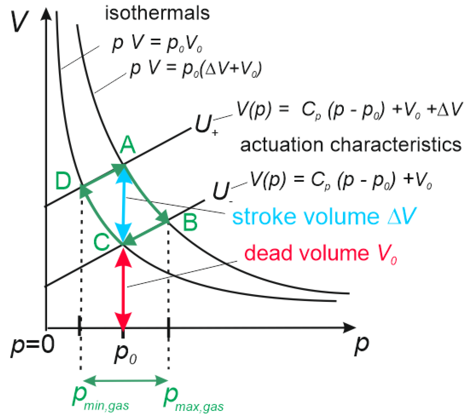
2.2. Pump Cycle of Micropumps Operated with Gases
The relation between the displaced volume and the pressure inside the pump chamber in dependence to the voltage can be approximated as a linear behaviour, depicted in Equation (1). Neglecting the piezoceramic hysteresis and assuming Kirchhoff plate theory, the simplified formula is denoted [26]:
The coefficients and are derived analytically in [26,34] and assuming round geometry for piezo as well as diaphragm. It should be mentioned that as well as are extended analytically expressions shown in the annex of reference [28]. They depend on the thicknesses () and radii () of piezo and diaphragm as well as Young’s moduli () and Poisson ratio of the silicon diaphragm. Additionally, is direct proportional to the transverse piezo coefficient . This coefficient describes the relative lateral shrinking of the piezo ceramics, if an electrical field is applied in vertical direction. The transverse piezo coefficient as well as is always negative. The voltage stroke multiplied with represent the maximal actuator stroke volume without back pressure. The thermal expansion coefficients of silicon and piezo are necessary to estimate the vertical shift of the actuator diaphragm with a changing temperature. This temperature change influences the dead volume and occurs either during the manufacturing process (e.g., if the glue is hardened at a higher temperature) or during operation (if the pump is not operated at ambient temperature).
The primary obstacle for using piezo-driven MEMS pumps as vacuum pumps is optimizing the compression ratio through increasing the stroke volume and decreasing the dead volume. To illustrate this challenge, we propose a p-V diagram in which the x-axis represents the absolute pressure in the pump chamber and the y-axis represents the volume of the pump chamber, which is enclosed by the actuation diaphragm and check valves. This diagram clearly illustrates the significant impact of both the stroke volume and dead volume on the target parameter .
With that, the pump cycle is described in a p-V diagram, depicted in Figure 5. Linear behaviour for the negative voltage and the positive voltage is assumed. The calculated dead volume of the micropump consists of the remaining pump chamber volume, when the diaphragm is at the lower returning point as well as a certain dead volume from the flap valves. The model assumes an operation of the micropump at atmosphere pressure with a rapid voltage switch between and with a certain operation frequency . A is the starting point of the cycle with a positive electrical voltage and assuming a stable actuator position after the end of the supply mode. While the actuation voltage decreases, the gas inside the pump chamber is compressed rapidly, for instance, during a time range of . As depicted in the p-V diagram (Figure 5), the pump follows according to its equation of state compressing the gas volume until the actuation characteristics of state B is reached. During that short time no significant flow through the valve occurs, resulting in a maximum over pressure achieved via the compression. The outlet valve opens and gas flows during a longer time scale towards the outlet, representing the pump mode. Figure 5 depicts this situation during the pressure and volume decrease from state B to state C. At state C, the pump outlet valve is pressure balanced with the periphery and the entire stroke volume is pumped to the outlet, assuming a neglectable leakage flow through the inlet valve. It is considered a stable position after the end of the pump mode.
Figure 5.
p-V diagram of the pump cycle of a micropump operating at atmosphere pressure pumping gas.
Defined by the operation frequency at , the negative voltage is applied rapidly, resulting in an upward movement of the diaphragm towards state D.
The pump chamber volume is increasing, so the gas is expanding to a minimum pressure. The corresponding pressure results in a gas flow through the opened inlet valve inside the pump chamber. This phase is named supply mode, until the inlet valve is pressure balanced and state A is reached. The pump cycle is now completed.
The volume difference between the two actuator positions A and C is defined as stroke volume . Without back pressure, the pump cycle transports this volume from the inlet to the outlet. An operational frequency causes the pump cycle to be repeated, which is assumed to be sufficiently small to perform the entire stroke with a stroke volume . The result is an average flow rate of achieved by the pump. The remaining volume in the pump chamber and the valve unit is defined as dead volume . It is calculated with the diaphragm actuator in its lowest position at (Figure 5). The compression ratio can be defined as the ratio between the maximal stroke volume and the dead volume .
Combining the actuator characteristics with the isothermals according to Figure 5, the pressures and can be calculated analytically, depicted in Equations (4) and (5).
In order to achieve the smallest possible absolute pressure, it is important to minimize the dead volume and to maximize the stroke volume . It should be mentioned that the hyperbolic shape of the isothermals has a larger gradient at smaller pressures. With that, a given volume stroke is achieving a smaller pressure stroke at the supply mode compared to the pump mode:
In this investigation, isothermal equations of state are assumed. In reality, the behaviour can be adiabatic or polytropic, in which case the fundamental conclusion is unaffected. With adiabatic behaviour, the radian is actually smaller, which causes higher pressure peaks.
Hysteresis occurs when the piezo is driven in big signal mode. When the external electrical field applied to the PZT is changed, the atoms react through displacing the load on a very short timescale (less than one microsecond), which is referred to as effect 1. However, the Weiss domains also change their size on a much slower timescale (above one millisecond and longer), referred to as effect 2. This second effect is associated with energy losses. Piezo creeping is a known effect that occurs after a step voltage is applied to the PZT. Initially, the piezo changes about 97% of the stroke immediately (due to effect 1), while the remaining 3% occurs on a logarithmic timescale (due to effect 2) and can take several seconds to achieve the full stroke [35].
To account for these effects, the micropump was operated continuously at a frequency of 100 Hz. This frequency is sufficiently low to avoid inducing piezo heating due to hysteresis losses. Heating of piezo ceramics are not observed until operating frequencies reach several kHz, and such high frequencies result in stroke loss, allowing the piezo creeping effect to be ignored. Additionally, because the voltage always starts and ends at the same level, the actuator is in a defined position.
2.3. Simulation of Performance Parameters of a Single Micropump
Through combining the input parameters from Table 1 and the theoretical explanation provided in the previous Section 2.2, we have calculated the output parameters for a single micropump, as shown in Table 2.
Table 2.
Simulation of performance parameters of a single micropump optimized for low pressure applications.
This micropump is optimized for low-pressure gas applications due to its high compression ratio (stroke volume: , dead volume: ). To minimize the dead volume, it is crucial to cycle the actuation diaphragm in close proximity to the pump chamber bottom, resulting in a small value of . The symbols and describe the distances from the pump chamber bottom to the actuator in the diaphragm centre at negative and positive voltage, respectively. Absolute actuator positions are calculated via considering additional effects such as the different thermal expansion coefficients of silicon and PZT ( and , respectively), the influence of the mounting voltage, and the operating temperature of the micropump (room temperature) in the simulation.
The most relevant outcome of the simulation is a of (absolute pressure), which would outperform the state of the art for a single stage micropump. Ideal valves with no leakages as well as ideal bending of the actuator diaphragm are assumed; the real is not expected to achieve that value.
2.4. Cascading Micropumps to Achieve Small Absolute Pressures
In this section, different methods for cascading micropumps in a series to enhance the performance of a single micropump and achieve lower absolute pressures are investigated. In order to achieve vacuum pressures, the outlet of stage is connected to the inlet of stage (Figure 6). Three different methods to cascade pumps are discussed:
Figure 6.
Different methods of cascading micropumps with 3 stages each to achieve vacuum pressure in the blue framed chamber compared to atmosphere pressure . In the just serial connected case (case 1), the actuators of every stage are working against atmospheric pressure. Pressure balanced outlet (case 2a) shows a housing on top of the actuator connected to the micropump outlet to a achieve a pressure balance between outlet and actuator. In the pressure balanced inlet (case 2b), the housing is connected to the micropump inlet of each stage.
- Cascading without pressure balance, where the micropumps are “just connected” in a series;
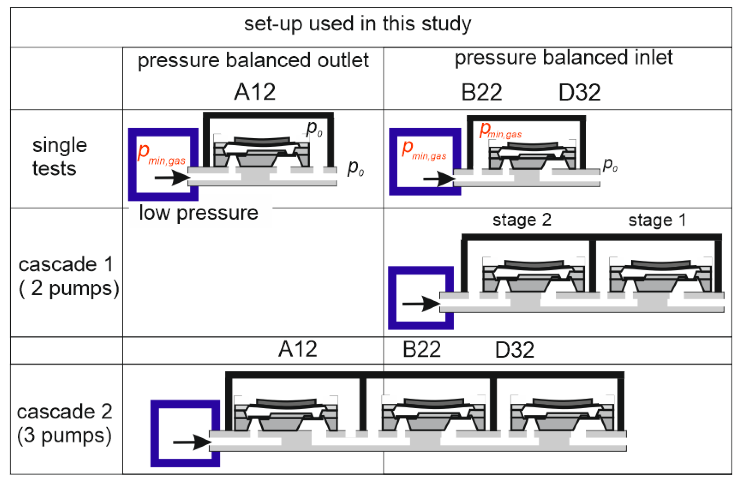
- Cascading with pressure balanced outlet, where the reference pressure above the piezo of stage is connected to the achieved pressure of stage ; and
- Cascading with pressure balanced inlet, where the reference pressure above the piezo of stage is connected to the achieved pressure of stage .
It needs to be demonstrated which concept is most promising to achieve the smallest absolute pressure.
2.4.1. Under Pressure with Micropumps: Just Serially Connected (Case 1)
Fluidic capacitance reduces at pressures below atmosphere pressure. Considering that every added stage after the initial atmosphere stage with the same stroke volume result in a smaller gain in under pressure. Especially if the absolute pressure is getting closer to vacuum, the gradient of the isothermals increases dramatically. For this situation a very high compression ratio (high stroke volume ΔV and small dead volume V0) is crucial to progress towards vacuum pressures.
The reduction of the actuator starting position of the stage 2 diaphragm due to the under pressure achieved at stage 1 does not result in an analogous reduction in dead volume, as the actuation diaphragm gets in contact with the pump chamber bottom (Figure 7). Furthermore, the stroke volume is reduced due to this touch down. In summary, a serial connection alone without pressure balancing is not useful to achieve small absolute pressures.
Figure 7.
Pump cycles of 3 consecutive stages for serial connection of micropumps, just serial connected without pressure compensation.
2.4.2. Under Pressure with Micropumps: Pressure Balanced (Case 2)
Cascading the micropumps via pressure balance ensures a constant dead volume as well as a constant stroke volume at higher stages to achieve negative pressure. The drawbacks regarding a reduction of the actuator stroke volume through touch down can be avoided (Figure 8). The increased fluidic capacitance due to the high gradients of the isothermal state equations are limiting the progress towards vacuum. However, it is evident that micropumps have to be pressure balanced if a small absolute pressure has to be achieved.
Figure 8.
Pressure-balanced configuration of a multistage of three micropumps to achieve negative pressure.
It is assumed that all micropumps of the multistage have the same design properties and the actuation signal is the same. In the following section, simulations are carried out to calculate the negative pressure of these configurations.
2.5. Simulation of a Pressure-Balanced Multistage Micropump for Negative Pressure
Based on the input parameters of the micropump (Table 1), the coefficients and are calculated using the analytical expression in the annex of ref. [28]. The stroke volume ΔV is calculated using Equation (3), and the dead volume is calculated using the geometry of the pump chamber, if the actuation diaphragm is in the lower position. Finally, the theoretical negative pressure of the micropump is calculated using Equation (6). In this approach, the simulation of stage 2 takes the pressure of stage 1 as a new reference pressure for stage 2 (instead of atmospheric pressure ). The pressure achieved at stage 2 is used as a reference pressure for stage 3. To calculate the actuator position for the pump cycle, the parameters from Table 1 are used. According to Figure 9, a minimum pressure of absolute for stage 1 is calculated. Stage 2 results in a amount of and for stage 3, a theoretical value is derived. As the gradient of the isothermals increases at small absolute pressures, an expansion of a volume during the supply mode results in a smaller pressure decrease per stage.
Figure 9.
Simulation result of a multistage with three pressure balanced silicon micropumps. All micropumps are identical in design, and have the same stroke volume and dead volume.
It is important to mention that no valve leakages are being considered in this simulation. Furthermore, ideal symmetric bending of the piezo-diaphragm is assumed. In addition to that, the electrically pretensed mounted actuator removes nearly all volume from the pump chamber during pump mode. In reality, due to inhomogeneities in the piezo ceramics, such as gas bubbles after sintering and inhomogeneous powder mixing before sintering, the bending curve of the actuators shows deviations from the symmetric bending curve. This results in an increased dead volume and reduced compression ratio. As a result, the experimental values of , , and are expected to not achieve the same performance compared to these simulation results.
3. Measurements
In the following section, measurements with piezoelectric actuated silicon micromembrane pumps to achieve vacuum pressures are conducted. The results of initial tests using single pumps and subsequent measurements using various multistage combinations are presented.
3.1. Stackable Housing Concept for Pressure-Balanced Micropump
Three micropumps were selected and assembled into micropump modules for carrying out the measurements. The modules, which can be stacked, include the micropump, sealing, and electrical connections, as shown in the picture on the right-hand side of Figure 10. The pump outlet is connected to a channel that leads directly to the unstructured bottom side of the module, while the inlet and the free space above the pump device are also connected. A silicone seal is integrated into the top side of the module to ensure an air-tight fluidic connection to the next module. The left-hand side picture of Figure 10 shows an example stack of three cascaded pump modules used for the measurements. The micropumps achieve the lowest pressure at the application or sensor 1 connector, and air is pumped from the application connector through the modules to the ambience or discharge connector.
Figure 10.
Micropump module in stackable housing with silicone sealing (right) and stack of three cascaded micropump modules including connectors to pressure sensors (left).
During the measurements of the stacked modules, the micropumps were actuated by a piezo amplifier connected to a waveform generator. Differential pressure sensors connected to the two left connectors were read out with an analogue-to-digital converter module from National Instruments and a measurement software. The data were recorded with a sampling rate of and the pumps were assembled and tested as seen in Figure 11.
Figure 11.
Different setups used in this study for single-pump tests of micropumps A12, B22, and D32 and multistage tests with two and three micropumps.
3.2. Minimum Gas Pressure for Single Pumps
As explained in Section 3.2, the separated silicon pump chips are assembled to pump modules (Figure 10). The modules with integrated pumps B22 and D32 are pressure balanced to the inlet pressure, so the actuator pressure is balanced to the minimum air pressure achieved by the respective micropump. Meanwhile the module with pump A12 is pressure balanced to the outlet atmosphere pressure. Figure 11 depicts those configurations schematically.
As a first standard characterization, the static actuator stroke of the separated pumps is measured. The piezoelectric actuator is pressure balanced to atmosphere pressure. Figure 12 illustrates the stroke from to . With a particular actuation voltage between and , the bottom of the pump chamber bottom gets touched by all actuators with a comparable stroke.
Figure 12.
Static actuator stroke of the selected three micropumps (A12, B22, D32). Actuator dimensions are depicted in Table 1. (PZT from PI Ceramics, type PI 151).
The absolute displacement of the actuator is mainly influenced by the actuation voltage and the pressure difference between the top and bottom side of the diaphragm. Therefore, the upper actuator position at minimum voltage during supply mode is stable for inlet pressure-balanced pumps. For outlet pressure-balanced pumps, the lower actuator position at positive voltage during pump mode is stable.
Figure 13 shows the time-dependent pressure which the single pump modules achieve while evacuating air from a test volume connected to a pressure sensor. The sensor measures the differential pressure regarding the atmosphere. After a certain time of , the pump B22 achieved a pressure of (according to absolute), the pump D32 achieved (according to absolute), and pump A12 achieved (according to absolute).
Figure 13.
Measurement results of from the selected three micropumps (A12, B22, D32).
As shown in Figure 13, none of the micropumps were able to achieve the theoretically simulated value of 41.3 kPa absolute pressure (equivalent to −60.0 kPa relative to atmospheric pressure). Nevertheless, the performance required to achieve a negative pressure of approximately −50 kPa is much better than that of other piezo-driven micropumps with passive check valves, and even better than that of the best micro blowers. It can be assumed that the different performance from pumps B22 and D32 compared to pump D32 can be explained partly by leakage losses of the valve. The gradient of the characteristics in the beginning is proportional to the stroke volume . As the micropump A12 shows a smaller gradient, it can be assumed from this measurement that the stroke volume of pump A12 is also much smaller compared to the pumps B22 and D32. Those three micropumps are cascaded and characterized in the following section.
3.3. Minimum Gas Pressure for a Multistage of Two Micropumps (Pressure Balanced)
In the following measurement, depicted in Figure 14, the micropumps D32 and B22 are deployed in the multistage. The pressure sensor measurement data show the of pump D32, used for stage 1, as well as pump B22, employed in stage 2. After approximately , the pressure level of is reached, which corresponds to absolute pressure. The measurement begins at ambient pressure of around and drops exponentially below the application pressure.
Figure 14.
Time- and pressure-dependent cascaded micropumps. Two cascaded micropumps (B22, D32) achieve an absolute pressure of .
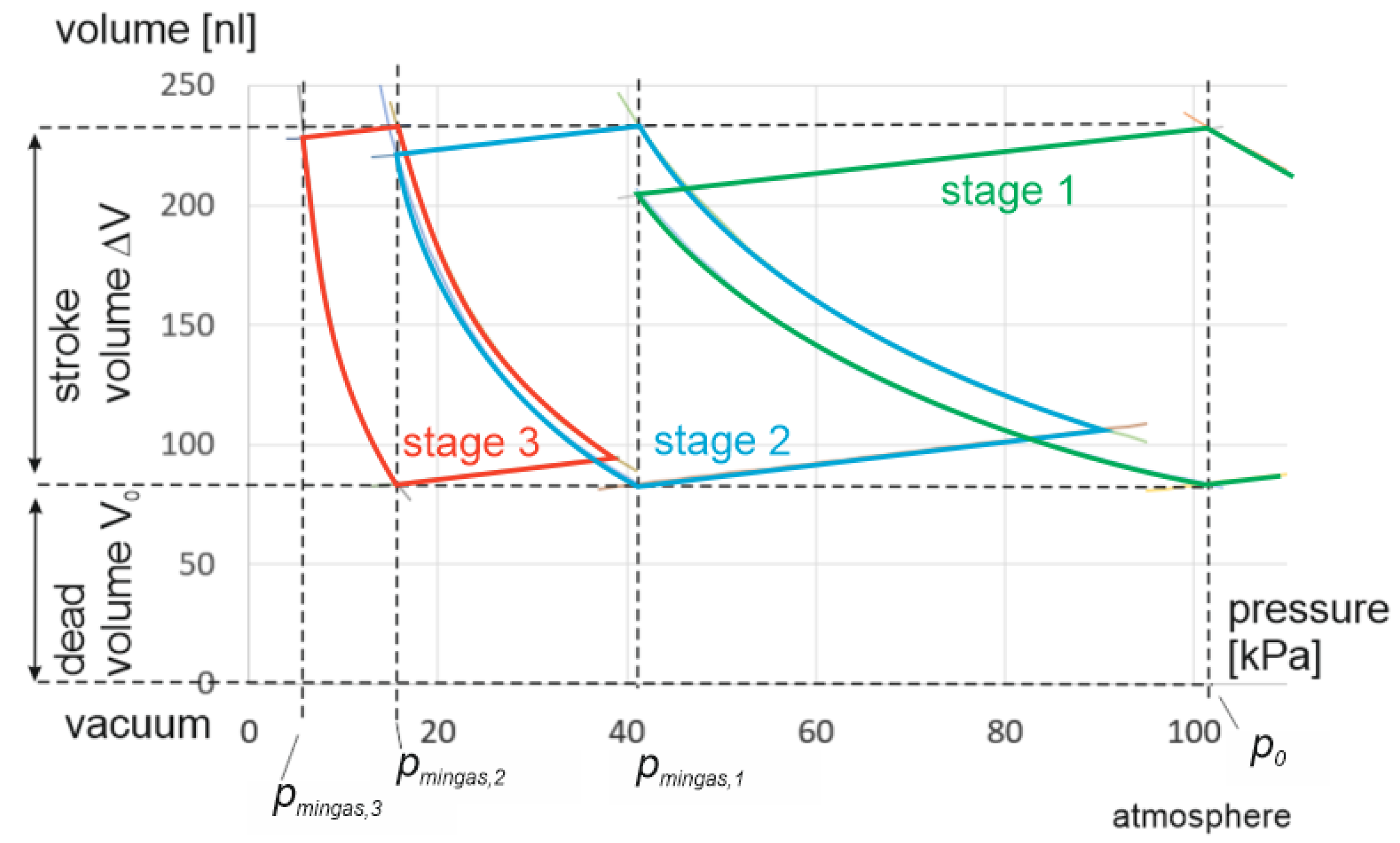
3.4. Minimum Gas Pressure for a Multistage of Three Micropumps (Pressure Balanced)
Figure 15 depicts the measurement after including micropump A12 to the cascade, forming a three-micropump pressure-balanced multistage. Pump D32 is used for stage 1, B22 for stage 2, and A12 is utilized for stage 3. Although the single-pump performance of A12 is significantly lower compared to B22 and D32 (Figure 13), an improvement of the minimum vacuum gas pressure to a level of absolute is achieved.
Figure 15.
Minimum air inlet pressure measurement result in dependence of time with a multistage of three micropumps. D32 in stage 1, B22 in stage 2, and A12 for stage 3 achieved an absolute pressure of in approximately .
4. Discussion and Outlook
The single micropumps achieved low absolute gas pressures of , , and . Although this result is superior compared to the state of the art, in theory, a value of absolute should be feasible. The multistage configuration with two micropumps achieved an absolute gas pressure of , and the multistage configuration with three pumps reached an absolute gas pressure of . Although, to our knowledge, this is the first time for a mechanical micropump device to generate such a low absolute gas pressure. Theoretically, an absolute gas pressure of and, for stage 3, an absolute gas pressure of , are calculated.
4.1. Discussion
The difference between simulation and measurement can be partly explained in a qualitative way using the following reasons:
- Model simplifications: The pressure-balanced configuration model assumes no influence of the pump actuation characteristics through generating negative pressure. This assumption is not true, as the negative pressure generated by the pump lifts the diaphragm upwards away from the pump chamber bottom. As a result, the dead volume of the micropump increases and the compression ratio decreases. This effect reduces the ability to achieve high negative pressures.
- Tolerances in material properties: In the PZT ceramics calculation, a homogeneous material and a homogenous coefficient is assumed. This assumption is inaccurate due to trapped bubbles during the sintering process as well as inhomogeneous powder mixing that may occur in the PZT ceramics production process. Considering that, the bending characteristics of an actuation diaphragm are not symmetric. This influence may reduce the actuator stroke volume and increase the dead volume. Both parameters have a significant influence on the compression ratio, which is the key parameter to achieve low gas pressures.
- Valve leakages: The passive silicon flap valve forms a hard-hard seal between the valve cantilever and valve seat. Although the silicon flap valve is accurately placed above the valve seat and the sealing surface is polished silicon without plastic deformations during bonding, there exist several possibilities for gaps at the valve seat leading to leakages:
- 1.
- After removing a sacrificial layer (nitride/oxide) of in the valve manufacturing process, there is an initial gap between cantilever and valve seat.
- 2.
Both issues are a source of additional leakages, reducing the vacuum pump performance.
- Squeeze film damping: The micropump has been operated at a frequency of . In order to reduce the micropump dead volume, the pretension of the diaphragm was adjusted so the diaphragm nearly touches the pump chamber bottom (a distance below was envisaged). This is important to reduce the dead volume . However, at these small pump chamber heights, squeeze film damping occurs, and the time available for supply mode and pump mode might not be sufficient to push the gas out of the region between diaphragm and pump chamber bottom, which reduces the effective stroke volume.
4.2. Outlook
This study discussed how to design a micropump assembly to achieve low gas pressures. For further improvements in the direction of coarse vacuum, the following steps are envisaged:
- Reduce leakages of the microvalves: Different design modifications to reduce both discussed gaps in hard-hard sealing are realized.
- Optimize valve bending at small absolute pressures: Mechanical cantilever valves open and close according to the pressure difference generated by the actuator movement. In a multistage with multiple micropumps upstream, just a few of pressure difference is available to open the valve. In an optimized version of this multistage configuration, every stage has its own valve geometry adapted for each pressure regime.
- Research in physical properties at small absolute pressures: With very small remaining gap heights in the micrometer range, the leakage rate is not only defined by the convection with Navier–Stokes equations, but also by self-diffusion. The theory describing the gas leakages of microvalves has to be extended in order to optimize the design of the valves adapted for these self-diffusion properties.
- Model adaption: The model will be extended with an implementation of the actuator diaphragm lifting effect for the pressure-balanced micropump due to the generated negative pressure.
- Actuator optimization: Another potential optimization strategy involves adapting the micropump design as well as the actuation voltage for the individual stages. Especially for stages closer to the vacuum, micropumps with large compression ratios and a reduced blocking pressure are advantageous. The design of the piezo-diaphragm actuator has a trade-off between stroke volume (proportional to the compression ratio) and blocking pressure. Both applications rely on micropumps optimized for these requirements. For these optimizations, the p-V diagram provides a guideline.
Author Contributions
Conceptualization, M.R. and D.A.; methodology, M.R. and M.W.; validation, M.W. and A.W.; formal analysis, M.R.; investigation, D.A. and Y.C.; resources, D.A.; data curation, M.W.; writing—original draft preparation, M.R. and D.A.; writing—review and editing, D.A.; visualization, M.R. and D.A.; supervision, M.R.; project administration, D.A.; funding acquisition, A.W. and M.R. All authors have read and agreed to the published version of the manuscript.
Funding
This research was funded by Deutsche Forschungsgemeinschaft (German Research Foundation) with grant number KU 3410/1-1.
Institutional Review Board Statement
Not applicable.
Informed Consent Statement
Not applicable.
Data Availability Statement
If data is required, please get in touch with the corresponding author for access.
Acknowledgments
We kindly thank the Fraunhofer EMFT silicon micropump group for the supply of micropump samples.
Conflicts of Interest
The authors declare no conflict of interest.
References
- Bußmann, A.B.; Grünerbel, L.M.; Durasiewicz, C.P.; Thalhofer, T.A.; Wille, A.; Richter, M. Microdosing for drug delivery application—A review. Sens. Actuators A Phys. 2021, 330, 112820. [Google Scholar] [CrossRef]
- Herz, M.; Kibler, S.; Söllner, M.; Scheufele, B.; Richter, M.; Lueth, T.C.; Bock, K. Entwicklung einer energieeffizienten piezoelektrischen Hochfluss-Mikropumpe für Methanol-Brennstoffzellen. Mikrosystemtechnik-Kongress 2011, 4, 74–77. [Google Scholar]
- Heppner, J.D.; Walther, D.C.; Pisano, A.P. The design of ARCTIC: A rotary compressor thermally insulated μcooler. Sens. Actuators A Phys. 2007, 134, 47–56. [Google Scholar] [CrossRef]
- Jousten, K. Handbuch Vakuumtechnik; Springer Fachmedien Wiesbaden: Wiesbaden, Germany, 2018. [Google Scholar]
- Tassetti, C.-M.; Mahieu, R.; Danel, J.-S.; Peyssonneaux, O.; Progent, F.; Polizzi, J.-P.; Machuron-Mandard, X.; Duraffourg, L. A MEMS electron impact ion source integrated in a microtime-of-flight mass spectrometer. Sens. Actuators B Chem. 2013, 189, 173–178. [Google Scholar] [CrossRef]
- van Someren, B.; van Bruggen, M.J.; Zhang, Y.; Hagen, C.W.; Kruit, P. Multibeam Electron Source using MEMS Electron Optical Components. J. Phys. Conf. Ser. 2006, 34, 1092–1097. [Google Scholar] [CrossRef]
- Grzebyk, T. MEMS Vacuum Pumps. J. Microelectromech. Syst. 2017, 26, 705–717. [Google Scholar] [CrossRef]
- Defense Advanced Research Projects Agency. Mighty Micropumps: Small but Powerful Vacuum Pumps Demonstrated: DARPA Creates Microscale Pumps to Evacuate Tiny Vacuum Chambers. Available online: https://www.darpa.mil/news-events/2013-06-04 (accessed on 9 May 2023).
- Reichelt Chemietechnik GmbH + Co. Mini-Vakuum-Membranpumpe für Gasförmige Medien und Reinstmedien. Available online: https://www.rct-online.de/de/pumpen/gaspumpen/mini-vakuum-membranpumpe-fuer-gasfoermige-medien-und-reinstmedien (accessed on 11 May 2023).
- Cumeras, R.; Figueras, E.; Davis, C.E.; Baumbach, J.I.; Gràcia, I. Review on Ion Mobility Spectrometry. Part 1: Current instrumentation. Analyst 2015, 140, 1376–1390. [Google Scholar] [CrossRef] [PubMed]
- Bäther, W.; Raupers, B.; Lehmann, S. Gas-Measuring Device: Patent Application Publication. U.S. Patent US 2016/0327532 A1, 9 January 2015. [Google Scholar]
- Murata Manufacturing Co., Ltd. Microblower MZB3004T04: Microblower (Air Pump). Available online: https://www.murata.com/en-eu/products/mechatronics/fluid/overview/lineup/microblower_mzb3004t04 (accessed on 17 May 2023).
- Astle, A.; Paige, A.; Bernal, L.P.; Munfakh, J.; Kim, H.; Najafi, K. Analysis and Design of Multistage Electrostatically-Actuated Micro Vacuum Pumps. In Microelectromechanical Systems; ASMEDC: New York, NY, USA, 2002; pp. 477–486. [Google Scholar]
- Kim, H.; Astle, A.A.; Najafi, K.; Bernal, L.P.; Washabaugh, P.D. An Integrated Electrostatic Peristaltic 18-Stage Gas Micropump With Active Microvalves. J. Microelectromech. Syst. 2015, 24, 192–206. [Google Scholar] [CrossRef]
- Zengerle, R.; Ulrich, J.; Kluge, S.; Richter, M.; Richter, A. A bidirectional silicon micropump. Sens. Actuators A Phys. 1995, 50, 81–86. [Google Scholar] [CrossRef]
- Leistner, H.; Wackerle, M.; Congar, Y.; Anheuer, D.; Roehl, S.; Richter, M. Robust Silicon Micropump of Chip Size 5 × 5 × 0.6 mm3 with 4 mL/min Air and 0.5 mL/min Water Flow Rate for Medical and Consumer Applications. In Actuator 2021, Proceedings of the International Conference and Exhibition on New Actuator Systems and Applications: GMM Conference, Online Event, 17–19 February 2021; Schlaak, H., Ed.; VDE Verlag GmbH: Berlin, Germany; Offenbach, Germany, 2021; pp. 113–116. [Google Scholar]
- Richter, M.; Wackerle, M.; Kibler, S.; Biehl, M.; Koch, T.; Müller, C.; Zeiter, O.; Nuffer, J.; Halter, R. Miniaturized drug delivery system TUDOS with accurate metering of microliter volumes. In Proceedings of the SENSOR, International Conference on Sensors and Measurement Technology, 16, AMA Conferences, Nürnberg, Germany, 14–16 May 2013; pp. 420–425. [Google Scholar]
- Du, M.; Ma, Z.; Ye, X.; Zhou, Z. On-chip fast mixing by a rotary peristaltic micropump with a single structural layer. Sci. China Technol. Sci. 2013, 56, 1047–1054. [Google Scholar] [CrossRef]
- Pankhurst, P.; Abdollahi, Z.M. Evaluation of a novel portable micro-pump and infusion system for drug delivery. IEEE Eng. Med. Biol. Soc. Annu. Conf. 2016, 2016, 465–468. [Google Scholar]
- Tanaka, S.; Tsukamoto, H.; Miyazaki, K. Development of Diffuser/Nozzle Based Valveless Micropump. J. Fluid Sci. Technol. 2008, 3, 999–1007. [Google Scholar] [CrossRef]
- Wong, C.C.; Aeschliman, D.P.; Henfling, J.F.; Sniegowski, J.J.; Rodgers, M.S. Development of an Ejector-Driven Micro-Vacuum Pump. In Micro-Electro-Mechanical Systems (MEMS); American Society of Mechanical Engineers: New York, NY, USA, 2001; pp. 485–493. [Google Scholar]
- Grzebyk, T.; Górecka-Drzazga, A.; Dziuban, J.A. Glow-discharge ion-sorption micropump for vacuum MEMS. Sens. Actuators A Phys. 2014, 208, 113–119. [Google Scholar] [CrossRef]
- Green, S.R.; Malhotra, R.; Gianchandani, Y.B. Sub-Torr Chip-Scale Sputter-Ion Pump Based on a Penning Cell Array Architecture. J. Microelectromech. Syst. 2013, 22, 309–317. [Google Scholar] [CrossRef]
- Gupta, N.K.; An, S.; Gianchandani, Y.B. A monolithic 48-stage Si-micromachined Knudsen pump for high compression ratios. In Proceedings of the 2012 IEEE 25th International Conference on Micro Electro Mechanical Systems (MEMS), Paris, France, 29 January–2 February 2012; IEEE: Piscataway, NJ, USA, 2012; pp. 152–155. [Google Scholar]
- Vargo, S.E.; Muntz, E.P. Initial results from the first MEMS fabricated thermal transpiration-driven vacuum pump. In Proceedings of the AIP Conference Proceedings, Sydney, Australia, 9–14 July 2000; pp. 502–509. [Google Scholar]
- Herz, M.; Horsch, D.; Wachutka, G.; Lueth, T.C.; Richter, M. Design of ideal circular bending actuators for high performance micropumps. Sens. Actuators A Phys. 2010, 163, 231–239. [Google Scholar] [CrossRef]
- Lee, S.; Yee, S.Y.; Besharatian, A.; Kim, H.; Bernal, L.P.; Najafi, K. Adaptive gas pumping by controlled timing of active microvalves in peristaltic micropumps. In Proceedings of the TRANSDUCERS 2009—2009 International Solid-State Sensors, Actuators and Microsystems Conference, Denver, CO, USA, 21–25 June 2009; IEEE: Piscataway, NJ, USA, 2009; pp. 2294–2297. [Google Scholar]
- Sandoughsaz, A.; Besharatian, A.; Bernal, L.P.; Najafi, K. Modular stacked variable-compression ratio multi-stage gas micropump. In Proceedings of the 2015 Transducers—2015 18th International Conference on Solid-State Sensors, Actuators and Microsystems (Transducers), Anchorage, AK, USA, 21–25 June 2015; IEEE: Piscataway, NJ, USA, 2015; pp. 704–707. [Google Scholar]
- Besharatian, A.; Kumar, K.; Peterson, R.L.; Bernal, L.P.; Najafi, K. Valve-only pumping in mechanical gas micropumps. In Proceedings of the 2013 Transducers & Eurosensors XXVII: The 17th International Conference on Solid-State Sensors, Actuators and Microsystems (Transducers & Eurosensors XXVII), Barcelona, Spain, 16–20 June 2013; IEEE: Piscataway, NJ, USA, 2013; pp. 2640–2643. [Google Scholar]
- Besharatian, A.; Kumar, K.; Peterson, R.L.; Bernal, L.P.; Najafi, K. A Scalable, modular, multi-stage, peristaltic, electrostatic gas micro-pump. In Proceedings of the 2012 IEEE 25th International Conference on Micro Electro Mechanical Systems (MEMS 2012), Paris, France, 29 January–2 February 2012; pp. 1001–1004. [Google Scholar]
- Le, S.; Hegab, H. Investigation of a multistage micro gas compressor cascaded in series for increase pressure rise. Sens. Actuators A Phys. 2017, 256, 66–76. [Google Scholar] [CrossRef]
- McNamara, S.; Gianchandani, Y.B. A micromachined Knudsen pump for on-chip vacuum. In Proceedings of the TRANSDUCERS ’03, 12th International Conference on Solid-State Sensors, Actuators and Microsystems, Digest of Technical Papers (Cat. No.03TH8664), Boston, MA, USA, 8–12 June 2003; IEEE: Piscataway, NJ, USA, 2003; pp. 1919–1922. [Google Scholar]
- Richter, M. Modellierung und Experimentelle Charakterisierung von Mikrofluidsystemen und deren Komponenten. Ph.D. Thesis, Universität der Bundeswehr München, München, Germany, 1998. [Google Scholar]
- Herz, M. Optimierung der Förderrate einer Piezoelektrischen Hochleistungs-Mikropumpe. Ph.D. Thesis, Technische Universität München, München, Germany, 2011. [Google Scholar]
- PI Ceramic GmbH. Piezoelectric Ceramic Products: Fundamentals, Characteristics and Applications. Catalogue 2016, CAT125E, R3. [Google Scholar]
Disclaimer/Publisher’s Note: The statements, opinions and data contained in all publications are solely those of the individual author(s) and contributor(s) and not of MDPI and/or the editor(s). MDPI and/or the editor(s) disclaim responsibility for any injury to people or property resulting from any ideas, methods, instructions or products referred to in the content. |
© 2023 by the authors. Licensee MDPI, Basel, Switzerland. This article is an open access article distributed under the terms and conditions of the Creative Commons Attribution (CC BY) license (https://creativecommons.org/licenses/by/4.0/).