Article

Predefined-Time Fault-Tolerant Trajectory Tracking Control for Autonomous Underwater Vehicles Considering Actuator Saturation

1
Science and Technology on Underwater Vehicle Laboratory, Harbin Engineering University, Harbin 150001, China
2
Liao Shen Industries Group Co., Ltd., Shenyang 110045, China
*
Author to whom correspondence should be addressed.
Actuators 2023, 12(4), 171; https://doi.org/10.3390/act12040171
Submission received: 22 March 2023 / Revised: 8 April 2023 / Accepted: 10 April 2023 / Published: 12 April 2023
(This article belongs to the Section Control Systems)

Abstract

:
This paper presents the design of two predefined-time active fault-tolerant controllers for the trajectory tracking of autonomous underwater vehicles (AUVs) which can address actuator faults without causing actuator saturation. The first controller offers improved steady-state trajectory tracking precision, while the second ensures a nonsingular property. Firstly, a predefined-time sliding mode controller is formulated based on a predefined-time disturbance observer by integrating a novel predefined-time auxiliary system to prevent the control input from exceeding the actuator’s physical limitations. Subsequently, a non-singular backstepping controller is introduced to circumvent potential singularities in the sliding mode controller, guaranteeing that the trajectory tracking error is uniformly ultimately bounded (UUB) within the predefined time. Additionally, theoretical analysis and simulation results are presented to illustrate the advantages of the proposed method.

1. Introduction

Currently, autonomous underwater vehicles (AUVs) are capable of replacing humans in accomplishing various underwater tasks, such as exploration, mapping, and monitoring. Trajectory tracking controller design plays a crucial role in these tasks.
To study the dynamics of a nonlinear system, two modeling methods are usually considered: linear parameter-varying (LPV) modeling [1] and nonlinear modeling. LPV models offer lower computational complexity compared to nonlinear models, making them easier to implement in real-time control applications. This is particularly advantageous when computational resources are limited. Moreover, LPV models can be readily combined with Kalman filters for state estimation in the presence of measurement noise, providing a systematic and well-established approach to handle noisy measurements and improve the overall system performance. LPV models capture certain types of nonlinearities by considering parameters that vary with the operating conditions, allowing the model to adapt to different conditions and making it suitable for a range of applications. LPV models enable the design of controllers that can be optimized for specific operating points or conditions, potentially leading to improved performance in these specific conditions compared to a more general nonlinear controller. These advantages make LPV models an attractive choice for certain applications where the trade-offs between modeling accuracy, computational complexity, and ease of implementation are critical consideration.
However, when an AUV operates in a complex flow environment (e.g., tidal currents, waves, and eddies), LPV models may not accurately capture the complex hydrodynamic effects on the AUV’s motion. In this case, a nonlinear model can better represent the impact of the flow environment on the AUV, thereby improving control performance. When an AUV performs high-speed maneuvering tasks, such as emergency obstacle avoidance or rapid search, it may experience large acceleration and angular velocities. In this situation, nonlinear effects (such as inertial coupling and hydrodynamic nonlinearities) become more significant, requiring the use of nonlinear models for more accurate modeling. For precise trajectory tracking tasks (e.g., underwater sampling and archaeological exploration), there are higher requirements for the accuracy of the AUV’s position and attitude. A nonlinear model can provide a more accurate dynamic description, which helps to achieve high-precision trajectory tracking control. Notably, the actuators used in AUVs, such as thrusters or control surfaces, may exhibit nonlinear dynamics (e.g., saturation and hysteresis) that can significantly affect the AUV’s motion. Nonlinear models can better capture these actuator nonlinearities, resulting in more accurate and effective control strategies.
Indeed, linear control techniques, which are well-established and widely understood, can be directly applied to LPV models. This simplifies the controller design process, making it more accessible and easier to develop. However, to achieve high-precision tracking performance in an ocean environment, control laws should be created based on a nonlinear model of an AUV. In recent years, numerous successful developments in this area have been made, including robust control [2,3,4], quantization control [5,6], model-predictive control [7,8], adaptive control [9,10,11], fuzzy control [12,13,14] and prescribed performance control [15,16].
Although advancements in AUV control have satisfied stability requirements for trajectory tracking, tracking performance is only guaranteed over a nominal control law. Nevertheless, maintaining the same control performance when AUV actuators fail is challenging. Actuator faults, such as thruster entanglement or blade and rudder deformation, introduce additional disturbances. These external disturbances negatively impact tracking performance, reducing precision and potentially leading to system instability in trajectory tracking.
As a result, integrating fault-tolerant capabilities into AUV trajectory tracking control schemes is a reasonable choice [17]. Existing fault-tolerant control methods combine passive and active FTC techniques. Passive fault-tolerant methods utilize adaptive laws to treat the failures as uncertainties [18,19,20]. However, the complexity of the AUV operating environment makes it impossible to predict and eliminate all factors that lead to actuator faults [21]. For an active FTC with fault diagnosis and identification, further analysis of the methodologies reveals that a residual must be determined [22,23,24]. The designer should establish a threshold for this residual to detect and isolate faults. Subsequently, the normal control law is replaced by a sophisticated controller, which unfortunately wastes the design effort put into creating the original normal control law. To overcome this limitation, fault reconstruction methodologies have been explored for faults in both linear and nonlinear systems [15,25,26].
In the field of fault reconstruction design for control systems, various investigations have explored the use of estimators such as observers or Kalman filters to diagnose actuator faults. Common observer structures include Kalman’s, sliding mode, Tau’s extended, cubic, and linear observers. Although observers cannot handle stochastic disturbances, control system modeling and design often assume the presence of simple disturbances with known frequency characteristics to address this issue. Unknown input observer (UIO)-based fault reconstruction schemes are conventional solutions, but they assume that the actuator fault or its differential value are bounded by a known scalar, which may not always be the case. High-gain observers can address this limitation, but they introduce high-gain problems and cannot complete the task of reconstruction in finite time. Linear controllers in control problems usually bring exponential convergence rates, meaning that the system state reaches the equilibrium point with infinite time. To improve system performance near the equilibrium point, finite-time control algorithms have been proposed.
Sliding mode control, a widely used finite-time control algorithm, is an inherently robust control algorithm with a simple structure and clear physical meaning. AUV motion control can be classified into stabilization control and tracking control, with the latter being more complex due to its intricate dynamic model. Nevertheless, control algorithms for these two aspects are generally similar since the kinetic models are identical.
Finite-time control offers superior performance compared to non-finite-time control, providing better accuracy, robustness, and anti-interference. The concept of finite-time stability is crucial to introducing this control method and understanding its benefits. In particular, in the finite-time control area, predefined-time stability allows for the convenient determination of the upper boundary of the settling-time. Although the research on AUV predefined-time control remains relatively limited, it has been considered in various fields [4,27]. In [28], a predefined-time follower–leader formation tracking control for AUVs is addressed. For the AUV trajectory tracking control problem, Ref. [29] proposed a model-free, high-order sliding mode controller. However, these algorithms often overlook the effects of actuator failures while meeting the time requirements.
In addition to the predefined-time requirement in control, the input saturation constraint is another important issue. Input saturation constraints stem from the physical limitations of the actuators, such as the maximum motor speed and maximum rudder angle in AUVs. If the controller outputs a command larger than the physical limit that the actuator can handle, actuator saturation occurs. Notably, the predefined-time controller is prone to outputting large control input at an initial stage while meeting the time constraints. As a result, it is desirable to keep the control input within the actuator’s physical limitations. To avoid control input saturation, Zhu approximated the saturation function with a smooth function in [30]; Ref. [16] used an auxiliary system to compensate for saturation in the controllers, driving the controller output away from saturation zone. However, these methods did not consider the predefined-time convergence stability property.
In light of the above observations, this paper proposes a predefined-time, disturbance-observer-based, predefined-time fault-tolerant architecture for AUV trajectory tracking. The proposed control schemes have the following properties:
  • A predefined-time sliding mode controller is developed based on a predefined-time disturbance observer. This is achieved by incorporating a novel predefined-time auxiliary system to prevent the control input from surpassing the actuator’s physical limitations;
  • A non-singular backstepping approach is designed to avoid potential singularities in the predefined-time sliding mode controller, ensuring that the trajectory tracking error remains uniformly ultimately bounded (UUB) within the predefined time.
The remainder of the paper is organized as follows. Section 2 presents the mathematical model for a 5-DOF AUV system for trajectory tracking. In Section 3.1, a predefined-time lumped disturbance observer is presented. Section 3.2 presents a predefined-time sliding mode controller that avoids the actuator saturation. Then, to avoid the singularity problem in the sliding mode controller, Section 3.3 designs a nonsingular, practical predefined-time controller. Section 4 validates the effectiveness of the proposed control scheme through simulations. Finally, this paper is concluded in Section 5.
Notations:  R n  represents a real matrix with  n × n  elements;  I n  is the  n × n  identity matrix;   is the Euclidean norm;  λ min  refers to the minimum eigenvalues of the matrix;  sgn  is the sign function.

2. Preliminaries

2.1. AUV Dynamic Model

Consider the dynamics of the AUV in the following form [31]:
η ˙ = J η v M v ˙ + C R B v + C A v + D v v + g η = τ a c t + τ d
where  η = x , y , z , θ , ψ T  describes the position and Euler angle in the Earth-fixed frame;  v = u , v , w , q , r T  represents the linear and angle velocities of the AUV, such as in Figure 1 x , y ,  and  z  are positions;  θ , ψ  are the pitch and yaw angle;  u , v ,  and  w  are the velocities along the axes;  q  and  r  are the rotation velocity around the Y-axis and Z-axis;  J η  transforms the velocities from the body-fixed frame into the Earth-fixed frame:
J η = cos ψ cos θ sin ψ cos ψ sin θ 0 0 sin ψ cos θ cos ψ sin ψ sin θ 0 0 sin θ 0 cos θ 0 0 0 0 0 1 0 0 0 0 0 1 cos θ
M = diag m 1 , m 2 , m 3 , m 4 , m 5 T  is the inertial matrix of the AUV;  m 1 , m 2 ,  and  m 3  contain the effects of the AUV mass and the added mass:  m 1 = m X u ˙ , m 2 = m Y v ˙ , m 3 = m Z w ˙ X u ˙ , Y v ˙ ,  and  Z w ˙  reflect the hydrodynamic force acting on the AUV. Likewise,  m 4 = I y y M q ˙  and  m 5 = I z z N r ˙  attribute the inertial moments and hydrodynamic moments.
Remark 1.
Typically, the AUV’s mission tasks do not require high-frequency maneuverability. The elements in AUV state vector η are measurable in practice. It is clear that ultra-short baselines (USBL) can provide the position information; the electronic compass and gauge can provide the depth and attitude information; and the DVL and IMU can provide the linear velocity and angular velocity, respectively, which can be transformed into inertial frame by  J η .
Coriolis and the centrifugal matrix  C v  refer to the rotation effect of the body-fixed frame in the Earth-fixed frame.
C v = 0 0 0 m Z w ˙ w m Y v ˙ v 0 0 0 0 m X u ˙ u 0 0 0 m X u ˙ u 0 m Z w ˙ w 0 m X u ˙ u 0 0 m Y v ˙ v m X u ˙ u 0 0 0
The drag matrix  D v  models the resistance produced by the water and the AUV body:
D v = X u X | u | u | u | 0 0 0 0 0 Y v Y | v | v | v | 0 0 0 0 0 Z w Z | w | w | w | 0 0 0 0 0 M q M | q | q | q | 0 0 0 0 0 N r N | r | r | r |
The restoring moment matrix  g η = τ P τ B sin θ , 0 , τ P τ B cos θ , z B τ B sin θ , 0 T  comprises the moments provided by the relative position of the weight center and buoyance center;  τ P  and  τ B  represent the gravity and buoyance of the AUV;  z B  is the center of the buoyancy. Supposing that the AUV is water-sealed, the center of the weight and buoyancy are determined in the design process of the shape and arrangement. With proper design, the center of mass of the AUV should be located below its center of buoyancy. The lower weight center guarantees the inherent stability in the rolling degree of the AUV.
Next,  τ a c t  represents the actual driving force exerted on the AUV in the body-fixed frame. The external disturbance  τ d  shows the uncertain but bounded force except for the actuator force. Generally,  sat ( τ c ) = [ sat ( τ c 1 ) , sat ( τ c 2 ) , sat ( τ c 3 ) , sat ( τ c 4 ) , sat ( τ c 5 ) ] T  can describe the actuator saturation constraints of AUVs as  sat ( τ c i ) = min { | τ c i | , τ c i , max } sgn ( τ c i )  [30], where  τ c = [ τ c 1 , τ c 2 , τ c 3 , τ c 4 , τ c 5 ] T  provides the expected controller output;  τ c i , max  constrains the maximum output force and moments of the corresponding  i t h  degree of freedom.
Combined with the saturation constraints, the actuator faults with saturation constraints can be modeled as follows [32]:
τ f = K sat ( τ c ) + τ a
where a diagonal matrix  K = d i a g ( [ k 11 , k 22 , k 33 , k 44 , k 55 ] T )  describes the thruster effectiveness with  k i i [ 0 , 1 ] . Here,  k i i = 0  implies that the actuator on the corresponding degree of freedom is healthy, and  k i i = 1  means that the actuator is completely inefficient. Apart from these two extreme cases,  k i i ( 0 , 1 )  means that the actuator loss part of its effectiveness. Additionally,  τ a = [ τ a 1 , τ a 2 , τ a 3 , τ a 4 , τ a 5 ] T  denotes the unexpected additive actuator faults in the thruster model.
Hypothesis 1.
Thruster redundancy exists in the AUV actuator fault model. The redundancy guarantees that each degree of freedom has at least one operatable thruster. This thruster keeps the AUV fully actuated when the faults and failures occur.
With this assumption in consideration, the actual driving force  τ a c t  provided by the fault thrusters with saturation constraints has the form:
τ a c t = sat ( τ c ) τ f = ( I K ) sat ( τ c ) + τ d = ρ sat ( τ c ) + τ d
where  I  is an identity matrix with five dimension and  τ d = d τ a . The time-varying function  k i i ( t )  describes the health of thruster, satisfying that  0 k i i ( t ) k ¯ i i < 1 . This also implies that  0 < ρ ¯ ρ i λ min ( I K ) , where  ρ i = 1 k i i .
Remark 2.
According to Assumption 1, the AUV is still fully actuated when a fault occurs. The fully actuated model bounds the value of  k i i ( t ) .
Hypothesis 2. 
The external disturbance vector  τ d  is assumed to satisfy   | | τ d | | τ ¯ d , where   τ ¯ d  is a positive constant.
Remark 3.
External disturbances in the ocean environment are often caused by the ocean current and changes in the density, temperature, and salinity of the water. These causes of external disturbance mean that the disturbances usually have a limited range. Thus, Assumption 3 is reasonable.
Subsequently, the AUV dynamic model Equation (1) can be transformed into a Euler–Lagrange equation form [33]:
η ¨ = M η 1 ( C η η ˙ + D η η ˙ + g ( η ) ) + M η 1 J ( η ) T τ a c t + M η 1 J ( η ) T τ d
where  M η = M J 1 ( η ) , C η = [ C v M J 1 ( η ) J ˙ ( η ) ] J 1 ( η )  and  D η = D v J 1 ( η )  with  J ˙ ( η ) = J ( η ) S ( η ˙ )  and  S ( η ˙ )  is an antisymmetric matrix.
Define the AUV reference trajectory as  η d  and the trajectory tracking error as:
η e = η η d η ˙ e = η ˙ η ˙ d
Differentiating Equation (8) and substituting Equation (7) into Equation (8), one has:
η ¨ e = η ¨ η ¨ d   = M η 1 ( C η η ˙ + D η η ˙ + g ( η ) ) + M η 1 sat ( τ c ) + M η 1 τ d η ¨ d
Hypothesis 3.
The AUVs’ velocities have an upper bound; the desired tracking trajectory  η d  and its corresponding derivatives  η ˙ d  and  η ¨ d  should also have upper bounds.
Remark 4.
Typically, AUV underwater tasks do not require high-frequency maneuverability. That the low-frequency maneuverability of the AUVs implies that the velocities are bounded is reasonable in practice.
The control objective is to design a controller for an AUV closed-loop system to achieve trajectory tracking control with actuator faults. The designed controller should regulate the AUV’s tracking error to a compact set within a user-selected time without offending the physical limitation of the actuator output.

2.2. Definitions and Lemmas

Lemma 1
([34]). Considering a generalized nonlinear system,  x ˙ = f ( x ) , x ( t 0 ) = x 0  is the initial state of the system. If there exists a radially unbounded Lyapunov function  V ( x )  satisfied such that,
V ˙ ( x ) = π p T V 1 p / 2 + V 1 + p / 2
then the system   x ˙ = f ( x )  is called a predefined-time stable system.   p ( 0 , 1 ) is an adjustable parameter, and   T  is the user-defined upper boundary of the settling time.
While converging to an equilibrium point is the most desirable in the control designs, it is usually more practical to drive the states into a compact set around the equilibrium point in the actual application. Thus, the practical predefined-time stability is given as follows:
Lemma 2
([27]). If there exists a radially unbounded Lyapunov function  V ( x )  such that:
V ˙ ( x ) = π p T V 1 p / 2 + V 1 + p / 2 + ε
then the system  x ˙ = f ( x )  is called a practical predefined-time stable system. The upper boundary of the settling time (UBST) of the system is explicitly adjustable in the controller as  T p = 2 T p ( 0 , 1 )  is an adjustable parameter, and  0 < ε < .
Meanwhile, the convergence residual set is given as:
lim t T p x | V ( x ) min 2 ε p T π 2 2 p , 2 ε p T π 2 2 + p
Lemma 3
([35]). For any  z i R m , ( i = 1 n | z i | ) r i = 1 n | z i | r .
Lemma 4
([36]). For any vector  z R N , when  0 < a 1 1 , a 2 > 1 , the following inequalities are valid:
i = 1 N z i a 1 i = 1 N z i a 1 , i = 1 N z i a 2 N a 2 1 i = 1 N z i a 2

3. Main Results

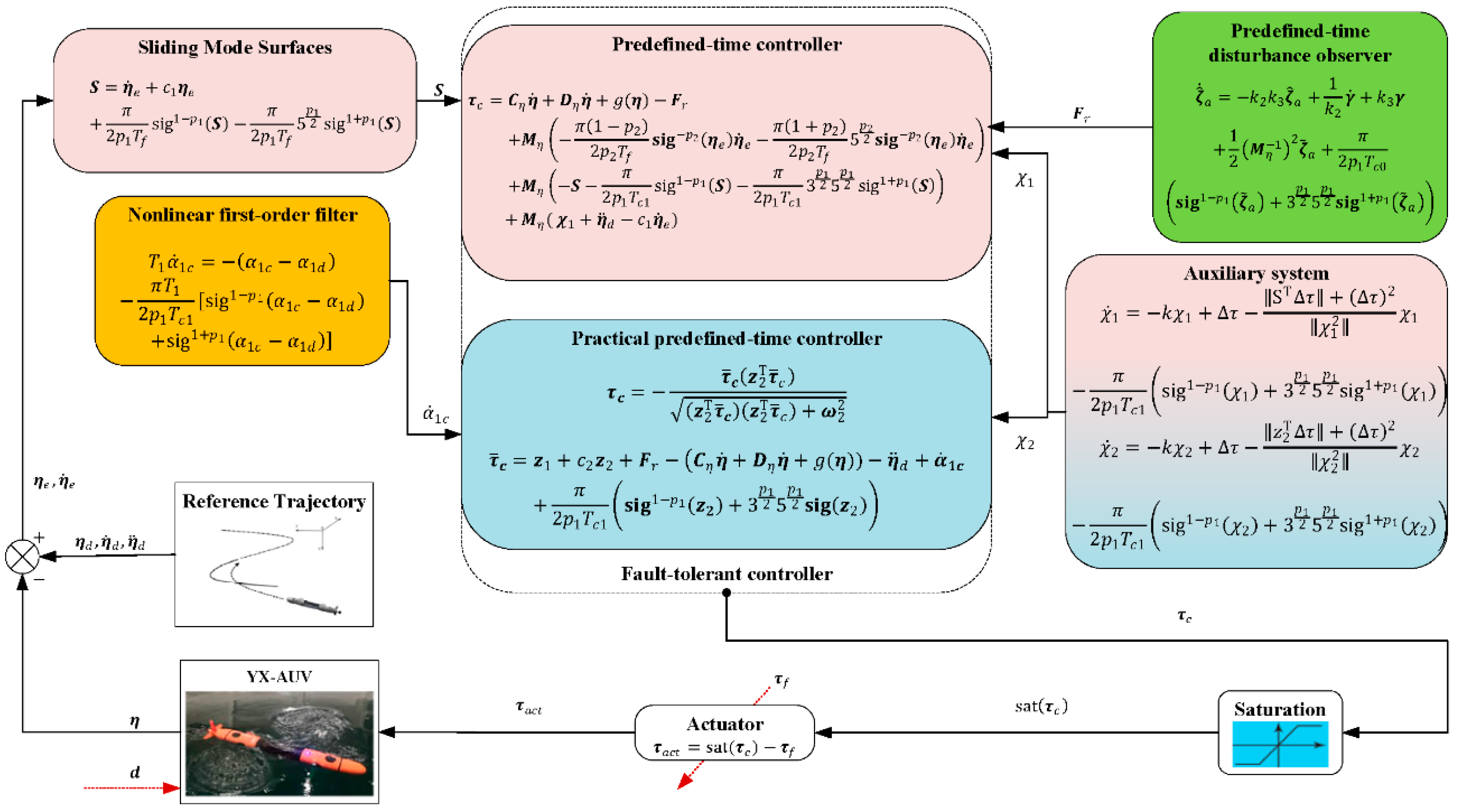
In this section, a predefined-time control architecture is designed for AUV trajectory tracking control to enhance the time-dependent trajectory tracking performance. The proposed control architecture comprises a predefined-time observer and a predefined-time controller. First, the predefined-time disturbance observer estimates the lumped disturbance, which includes the actuator fault. Then, the estimated disturbance is fed back to stabilize the closed-loop system within the predefined time. Additionally, considering the actuator saturation constraints, an auxiliary system is also incorporated into the proposed predefined-time controller to prevent the control input from exceeding the physical limitation. The entire predefined-time closed-loop trajectory tracking system is depicted in Figure 2.

3.1. Predefined-Time Sliding Mode Controller

In this section, a predefined-time disturbance observer is initially designed to estimate the lumped disturbance. The objective is to ensure that the lumped disturbance estimation error converges to zero within an adjustable predefined time. To achieve this predefined-time design goal, Lemma 1 serves as the foundation for the development of the predefined-time observer and the subsequent predefined-time sliding mode controller.
First, define a new variable  ζ a  composed of the control input  sat ( τ c )  and the known dynamics of the AUVs in Equation (7):
ζ a = k 1 0 t [ sat ( τ c ) + M ˙ η η ˙ C η η ˙ g ( η ) ζ a ] d s k 1 M η η ˙
where  k 1  is a positive constant.
Next, take the derivative of both sides of Equation (14); the change process of the auxiliary variable then has the form:
ζ ˙ a = k 1 ζ a k 1 f l
Subsequently, the output of the linear system in Equation (15) can be defined as  γ = k 2 ζ a . Then, the object of estimating the lumped disturbance  f l  is transformed into estimating the state of the linear system with a system output  γ .
Design a predefined-time disturbance observer as follows:
ζ ^ ˙ a = k 2 k 3 ζ ^ a + 1 k 2 γ ˙ + k 3 γ + 1 2 ( M η 1 ) 2 ζ ˜ a + π 2 p 1 T c 0 sig 1 p 1 ( ζ ˜ a ) + 3 p 1 2 5 p 1 2 sig 1 + p 1 ( ζ ˜ a )
where  ζ ^ a  is the estimation of variable  ζ a ζ ˜ a = ζ a ζ ^ a  represents the estimation error;  γ ˙  is the derivative of the linear system output  γ 0 < p 1 < 1  is an adjustable parameter;  k 3  is a positive constant.
Theorem 1. 
Considering the AUV trajectory tracking error dynamic model Equation (9) with lumped disturbance  f l , the proposed predefined-time disturbance observer in Equation (16) can reconstruct the lumped disturbance with in a predefined time  T c 0 , and the reconstructed disturbance  F r  has the form:
F r = 1 k 1 k 2 ( k 1 k 2 ζ ^ a + γ ˙ )
Remark 5. 
In the practical application of the AUV, the position and velocity of the AUV,  η  and  v , can be measured with the sensors equipped on the AUV. Therefore, the predefined-time disturbance observer can estimate the lumped disturbance with the states measured.
Proof of Theorem 1.
Select a candidate Lyapunov function:
V 0 = ζ ˜ a T ζ ˜ a
The derivative of  ζ ˜ a  has the following form:
ζ ˜ ˙ a = k 2 k 3 ζ ^ a k 2 k 3 ζ a 1 2 ( M η 1 ) 2 ζ ˜ a π 2 p 1 T c 0 sig 1 p 1 ( ζ ˜ a ) + 3 p 1 2 5 p 1 2 sig 1 + p 1 ( ζ ˜ a )   = k 2 k 3 ζ ˜ a 1 2 ( M η 1 ) 2 ζ ˜ a π 2 p 1 T c 0 sig 1 p 1 ( ζ ˜ a ) + 3 p 1 2 5 p 1 2 sig 1 + p 1 ( ζ ˜ a )
According to Lemma 4, by substituting Equation (19) into the derivative of  V 0 , one can obtain:
V ˙ 0 2 k 2 k 3 + λ min M η 1 2 V 1 π p 1 T c 0 i = 1 5 ζ ˜ a i 2 1 p 1 / 2 π p 1 T c 0 i = 1 5 ζ ˜ a i 2 1 + p 1 / 2   π p 0 T c 0 V 1 1 p 1 / 2 + V 1 1 + p 1 / 2
According Lemma 1 and Equation (20), the state estimation error  ζ ˜ a  will converge to zero within  T c 0 .
Consequently, define  F e = f l F r  to represent the reconstruction error:
F e = f l + ζ ^ a + 1 k 1 ζ ˙ a = f l + ζ ^ a + 1 k 1 ( k 1 ζ a k 1 f l ) = ζ ˜ a
With the predefined-time stability of the state estimation error  ζ ˜ a  from Equation (20), the reconstruction error  F e  also converges to zero within the selected time  T c 0 . Then, the lumped disturbance  f l  is approximated by  F r  within the predefined time  T c 0 .
The proof is completed now. □
With the lumped disturbance reconstructed in Theorem 1, two disturbance observer-based predefined-time controllers will be designed to achieve the desired trajectory tracking performance within a predefined time in the following sections.

3.2. Design of Predefined-Time Sliding Mode Controller

First, a predefined-time sliding manifold is formulated based on the trajectory tracking error  η e  defined in Equation (9):
S = η ˙ e + C 1 η e + π 2 p 2 T f sig 1 p 2 ( η e ) + π 2 p 2 T f 5 p 2 2 sig 1 + p 2 ( η e )
where  C 1 , p 2 , and  T f  are positive constants.
Theorem 2.
Assuming that the AUV trajectory tracking error lies on the surface  S = 0 , then the tracking error  η e  will converge to the origin within a predefined time  T f .
Remark 6. 
The motion of the AUV trajectory tracking error with initial condition  η e ( 0 )  is shown in Figure 3. As shown in Figure 3,  η e  will reach the predefined-time sliding mode surface  S  after  T s  and lie in  S = 0  thereafter based on Theorem 3. Then, according Theorem 2,  η e  will continue to converge to the equilibrium point  η e = 0  after  T f . In summary, the total settling time  T c  consists of two predefined periods:  T s  and  T f .
Proof of Theorem 2.
Once the AUV states reach the sliding mode surface  S  and stay there thereafter, it follows that:
η ˙ e = C 1 η e π 2 p 2 T f sig 1 p 2 ( η e ) π 2 p 2 T f 5 p 2 2 sig 1 + p 2 ( η e )
Select the Lyapunov candidate function  V η = η e T η e ; the derivative of  V η  then has the form:
V ˙ η 2 C 1 η e T η e π p 2 T f η e i 2 1 p 2 / 2 π p 2 T f η e i 2 1 + p 2 / 2   2 C 1 V η π p 2 T f V η 1 p 1 / 2 + V η 1 + p 1 / 2
The first term in Equation (24),  2 C 1 V η , guarantees that the tracking error  η e  is stable. Then, Lemma 1 guarantees the predefined-time convergence of  η e . □
Theorem 2 guarantees that the settling time of the tracking error does not depend on the initial state once  S = 0  is obtained. Subsequently, this section will continue to provide a controller to ensure that the AUV states reach the sliding mode surface S within a predefined time  T s . Additionally, considering that the actuator saturation constraints may have an adverse effect on the actuator, an auxiliary system is incorporated to avoid the control input going beyond the physical limitation of the actuator. Then, the predefined-time sliding mode controller is designed as follows:
τ c = C η η ˙ + D η η ˙ + g ( η ) F r   + M η η ¨ d C 1 η ˙ e π 1 p 2 2 p 2 T f sig p 2 η e η ˙ e π 1 + p 2 2 p 2 T f 5 p 2 / 2 sig p 2 η e η ˙ e   + M η S π 2 p 1 T s sig 1 p 1 ( S ) π 2 p 1 T s 3 p 1 / 2 5 p 1 / 2 sig 1 + p 1 ( S ) + M η χ 1
where  F r  is the estimated disturbance in Equation (17) and  χ 1  is an auxiliary variable incorporated to attenuate the influence of the actuator saturation problem:
χ ˙ 1 = k χ 1 χ 1 + M η 1 Δ τ c S T M η 1 Δ τ c + 0.5 M η 1 Δ τ c 2 χ 1 2 χ 1 π 2 p 1 T s sig 1 p 1 ( χ 1 ) + 3 p 1 / 2 5 p 1 / 2 sig 1 + p 1 ( χ 1 ) χ 1 > χ 10 k χ 1 χ 1 π 2 p 1 T s sig 1 p 1 ( χ 1 ) + 3 p 1 / 2 5 p 1 / 2 sig 1 + p 1 ( χ 1 ) χ 1 χ 10
where  Δ τ c = sat ( τ c ) τ c  and  χ 10  is a positive constant to avoid the singularity.
Theorem 3. 
For the AUV closed-loop system described in Equation (7), subjected to the lumped disturbance  f l , with the predefined-time disturbance observer in Equation (16) and the predefined-time sliding mode controller in Equation (25), the AUV trajectory tracking error will converge to zero within the predefined settling time  T c = T f + T s .
Remark 7. 
A fundamental assumption about the predefined-time controller design is that actuator saturation does not affect the feasibility of control performance. Specifically, if the predefined time exceeds the maximum output that the actuator can provide, the output of the controller keeps the actuator in saturation all the time. In this case, a controller with an unreasonably predefined time cannot achieve the predefined-time stability provided by Theorem 3.
Remark 8 
The control parameter  p 1  should be carefully selected due to the existence of  p 1  in the controller term  sig p 1 ( η e ) . The negative parameters in the powers may lead to singularity in the proposed predefined-time sliding mode controller in Equation (25). The probability of generating singularity is a disadvantage of the proposed control law.
Proof of Theorem 3.
First, differentiating the proposed predefined-time sliding mode surface  S  in Equation (22), one has:
S ˙ = M η 1 F R S π 2 p 1 T s sig 1 p 1 ( S ) π 2 p 1 T s 3 p 1 / 2 5 p 1 / 2 sig 1 + p 1 ( S ) χ 1 + M η 1 Δ τ + M η 1 f l = M η 1 F r f l S π 2 p 1 T s sig 1 p 1 ( S ) π 2 p 1 T s 3 p 1 / 2 5 p 1 / 2 sig 1 + p 1 ( S ) χ 1 + M η 1 Δ τ c
Considering the definition of the variable  ζ ˜ a  and the actuator saturation auxiliary variable  χ 1 , choose the Lyapunov candidate function  V S  as:
V S = S T S + χ 1 T χ 1
Differentiate the Lyapunov candidate function in Equation (28):
V ˙ S 2 S T M η 1 F e π p 1 T s S i 2 1 p 1 / 2 + 3 p 1 / 2 5 p 1 / 2 S i 2 1 + p 1 / 2   S T χ 1 + 2 S T M η 1 Δ τ c + 2 χ 1 T χ ˙ 1
Since  F e = ζ ˜ a = 0  for  t > T c 0 , when substituting the derivative of  χ 1  in Equation (26) into Equation (29), Equation (29) becomes:
V ˙ S S T S π p 1 T s S i 2 1 p 1 / 2 + 3 p 1 / 2 5 p 1 / 2 S i 2 1 + p 1 / 2   π p 1 T s χ 1 i 2 1 p 1 / 2 + 3 p 1 / 2 5 p 1 / 2 χ 1 i 2 1 + p 1 / 2
Applying Lemma 4 again, one has:
V ˙ S π p 1 T s χ 1 T χ 1 + S T S 1 p 1 / 2 π p 1 T s 3 p 1 2 χ 1 T χ 1 + S T S 1 + p 1 / 2   π p 1 T s χ 1 T χ 1 + S T S 1 p 1 / 2 + χ 1 T χ 1 + S T S 1 + p 1 / 2   = π p 1 T s V S 1 p 1 / 2 + V S 1 + p 1 / 2
According to Equation (31) and Lemma 1, it can be obtained that  S 0  and  ζ ˜ a 0  after  T s . Considering the predefined-time stability in Theorem 2, it follows that the trajectory tracking error  η e = 0 , t T f  after reaching the sliding mode surface  S . Therefore, the trajectory tracking error  η e  satisfies:
η e ( t ) = 0 , t T s + T f
The proof of Theorem is completed now. □

3.3. Design of Nonsingular, Practical Predefined-Time Controller

Although Theorem 3 ensures that the closed-loop system for AUV trajectory tracking is a predefined-time stable system, using the proposed sliding mode controller Equation (25), the negative power component within the controller may introduce singularity issues in the closed-loop system. Consequently, we develop a nonsingular, practical predefined-time controller based on the backstepping design procedure to address this concern.
First, define the trajectory tracking error as  η e  and a virtual control input error  z 2  as follows:
η e = η η d , z 2 = η ˙ e α 1 c
where  a 1 c  is a filtered virtual control input. The filtered virtual control input is obtained by allowing the virtual control input  α 1 d  to pass through a nonlinear first-order filter:
T 1 α ˙ 1 c = ( α 1 c α 1 d ) π T 1 2 p 1 T c 1 sig 1 p 1 ( α 1 c α 1 d ) + sig 1 + p 1 ( α 1 c α 1 d )
where  T 1  is the time constant of the nonlinear first-order filter. With the nonlinear first-order filter in Equation (34), the differential term  α ˙ 1 c  can be directly acquired instead of calculating  α ˙ 1 d , which is required in the conventional backstepping method. Note that the first-order filter used here is nonlinear instead of a linear filter. This is because the linear filter cannot guarantee the predefined-time convergence in the AUV closed-loop system.
Choose the candidate Lyapunov function to stabilize the trajectory tracking error  η e :
V 1 = η e T η e
Differentiating the Lyapunov function  V 1  yields:
V ˙ 1 2 η e T z 2 2 c 1 η e T η e π p 1 T c 1 η e 2 p 1 + η e 2 + p 1 + 2 ω 1 + 2 η e T σ 1
Different with the virtual controller in conventional backstepping method, the virtual controller is proposed as follows:
α 1 d = α ¯ 1 d η e T α ¯ 1 d η e T α ¯ 1 d η e T α ¯ 1 d + ω 1 2
where  ω  is a positive constant, and
α ¯ 1 d = c 1 η e + π 2 p 1 T c 1 sig 1 p 1 ( η e ) + 3 p 1 / 2 5 p 1 / 2 sig 1 + p 1 ( η e )
Before analyzing the dynamic of  z 2 , the nonsingular property of the virtual control input  α 1 d  is reconsidered. We know that the conventional virtual control input has a form similar to  α ¯ 1 d . According to the definition of  α ¯ 1 d , one has:
α ¯ ˙ 1 d = c 1 η ˙ e + π 2 p 1 T c 1 1 p 1 η e p 1 η ˙ e + π 2 p 1 T c 1 1 + p 1 3 p 1 / 2 5 p 1 / 2 η e p 1 η ˙ e
The term  p 1  occurring in the equation seems to cause the singularity problem, as in the analysis of the proposed predefined-time sliding mode control law. However, the modified virtual control input  α 1 d  replaces  α ¯ 1 d  to solve this problem. In detail, differentiating the virtual control law in Equation (34) yields,
α ˙ 1 d = d α ¯ 1 d η e T α ¯ 1 d d t η e T α ¯ 1 d η e T α ¯ 1 d + ω 1 2 η e T α ¯ 1 d η e T α ¯ 1 d + ω 1 2 + α ¯ 1 d η e T α ¯ 1 d η e T α ¯ 1 d η e T α ¯ 1 d + ω 1 2 d η e T α ¯ 1 d η e T α ¯ 1 d + ω 1 2 d t
where
d α ¯ 1 d η e T α ¯ 1 d d t = α ¯ ˙ 1 d η e T α ¯ 1 d + α ¯ 1 d η ˙ e T α ¯ 1 d + α ¯ 1 d η e T α ¯ ˙ 1 d d η e T α ¯ 1 d η e T α ¯ 1 d + ω 1 2 d t = 1 2 η e T α ¯ 1 d η e T α ¯ 1 d + ω 1 2 η ˙ e T α ¯ 1 d η e T α ¯ 1 d + η e T α ¯ ˙ 1 d η e T α ¯ 1 d + η e T α ¯ 1 d η ˙ e T α ¯ 1 d + η e T α ¯ 1 d η e T α ¯ ˙ 1 d
Then, it can be found that  α ˙ 1 d  contains the original term  α ¯ ˙ 1 d , which may cause the singularity problem. Recalling the definition of  η e T α ¯ ˙ 1 d  again, one has:
η e T α ¯ ˙ 1 d = c 1 η e T η ˙ e + π 2 p 1 T c 1 1 p 1 η e 1 p 1 η ˙ e + π 2 p 1 T c 1 1 + p 1 3 p 1 / 2 5 p 1 / 2 η e 1 + p 1 η ˙ e
where the term  p 1  becomes  1 p 1 . According to the definition that  0 < p 1 < 1 , it can be found that the nonsingular property is guaranteed directly by the modified virtual controller.
Subsequently, by differentiating the virtual control input error  z 2 , one has:
z ˙ 2 = η ¨ η ¨ d α ˙ 1 c
Considering that the first-order filter introduces filtered error, define the filter error as  σ 1 = α 1 c α 1 d ; then, Equation (34) has the form:
α ˙ 1 c = 1 T 1 σ 1 π 2 p 1 T c 1 sig 1 p 1 ( σ 1 ) + sig 1 + p 1 ( σ 1 )
Similar to the design of virtual control law in Equation (37), design the actual control input  τ c  as follows:
τ c = τ ¯ c z 2 T τ ¯ c z 2 T τ ¯ c z 2 T τ ¯ c + ω 2 2
where  ω 2  is a positive constant, and  τ ¯ c  satisfies:
τ ¯ c = z 1 + c 2 z 2 + F R C η η ˙ + D η η ˙ + g ( η ) η ¨ d α ˙ 1 c + π 2 p 1 T c 1 sig 1 p 1 ( z 2 ) + 3 p 1 / 2 5 p 1 / 2 sig ( z 2 )
Correspondingly, modify the auxiliary system as follows:
χ ˙ 2 = k χ 2 χ 2 + M η 1 Δ τ c z 2 T M η 1 Δ τ c + 0.5 M η 1 Δ τ c 2 χ 2 2 χ 2 π 2 p 1 T c 1 sig 1 p 1 ( χ 2 ) + 3 p 1 / 2 5 p 1 / 2 sig 1 + p 1 ( χ 2 ) χ 2 > χ 20 k χ 2 χ 2 π 2 p 1 T c 1 sig 1 p 1 ( χ 2 ) + 3 p 1 / 2 5 p 1 / 2 sig 1 + p 1 ( χ 2 ) χ 2 χ 20
Define the Lyapunov function as:
V 2 = V 1 + z 2 T z 2 + σ 1 T σ 1 + χ 2 T χ 2
Differentiating  V 2 , one has:
V ˙ 2 = V ˙ 1 + 2 z 2 T z ˙ 2 + 2 σ 1 T σ ˙ 1 + 2 χ 2 T χ ˙ 2   = 2 c 1 1 η e T B 1 π p 1 T c 1 η e T η e 1 p 1 / 2 π p 1 T c 1 3 p 1 / 2 5 p 1 / 2 η e T η e 1 + p 1 / 2 + 2 ω 1 + σ 1 T σ 1 + 2 η e T z 2   2 z 2 T M η 1 C η η ˙ + D η η ˙ + g ( η ) + M η 1 τ c + M η 1 Δ τ c + M η 1 f l η ¨ d α ˙ 1 c   + 2 σ 1 T σ ˙ 1 + 2 χ 2 T χ ˙ 2
According to Theorem 1, when  t > T c 0 ζ ˜ a = 0 , by substituting the control law in Equation (45) and the definition of  χ 2  in Equation (47), one has:
V ˙ 2 2 c 1 1 z 1 T z 1 π p 1 T c 1 z 1 2 1 p 1 / 2 π p 1 T c 1 3 p 1 / 2 5 p 1 / 2 z 1 2 1 + p 1 / 2 + σ 1 T σ 1   2 ( c 2 1 ) z 2 T z 2 + 2 z 2 T M η 1 Δ τ π p 1 T c 1 z 2 2 1 p 1 / 2 + 3 p 1 / 2 5 p 1 / 2 z 2 2 1 + p 1 / 2 + 2 σ 1 T σ ˙ 1   π p 1 T c 1 χ 2 2 1 p 1 / 2 + 3 p 1 / 2 5 p 1 / 2 χ 2 2 1 + p 1 / 2 + 2 ω 1 + 2 ω 2
Consequently, based on the definition of  σ 1  and  α 1 d , one has:
σ ˙ 1 = α ˙ 1 c α ˙ 1 d = 1 T 1 σ 1 π 2 p 1 T c 1 sig 1 p 1 ( σ 1 ) + sig 1 + p 1 ( σ 1 ) α ˙ 1 d = 1 T 1 σ 1 π 2 p 1 T c 1 sig 1 p 1 ( σ 1 ) + sig 1 + p 1 ( σ 1 ) + B 1 η , η ˙ , η d , η ˙ d , σ 1
where  B 1 η , η ˙ , η d , η ˙ d , σ 1  is a continuous vector function.
Then, applying Young’s inequality, it can be obtained that:
2 σ 1 T σ ˙ 1 = 2 T 1 σ 1 T σ 1 + 2 σ 1 T B 1 2 T 1 σ 1 T σ 1 + σ 1 2 B 1 2 + 1
Hypothesis 4. 
According to the designed virtual control law in Equation (37), we assumed that there exists a positive constant  B M  that satisfies  B 1 B M .
Considering Assumption 4, the control parameters  c 1 , c 2 ,  and  c 3  and the time constant  T 1  can be chosen as
c 1 > 1 2 , c 2 > 1 2 , c 3 > 1 , T 1 < 2 B M + 1
Theorem 4. 
Considering the AUV closed-loop system in Equation (7) as consisting of disturbances, as characterized by Assumptions 1–4, combined with the predefined-time disturbance observer Equation (16), if the virtual control law and actual control law are provided by Equations (37) and (45), the closed-loop system is then a practical predefined-time stable system, and the trajectory tracking errors will converge to a set around zero within  2 T c 1 . In addition, the actual control input will not avoid the actuator saturation constraint by combing the auxiliary system in Equation (47).
Remark 9.
The modified virtual control input  α 1 d  contributes to the nonsingular property. However, as stated by Theorem 4, the nonsingular property is based on the practical trajectory tracking precision instead of an asymptotic tracking. The selection of the controller is based on the actual requirement: the sliding mode controller has higher steady-state trajectory tracking precision and the other has a nonsingular property.
Proof of Theorem 4.
With the properly selected parameters in Equation (53), one can obtain that:
V ˙ 2 2 c 1 1 z 1 T z 1 2 ( c 2 1 ) z 2 T z 2 π p 1 T c 1 z 1 2 1 p 1 / 2 π p 1 T c 1 3 p 1 / 2 5 p 1 / 2 z 1 2 1 + p 1 / 2 + 2 ω 1 + 2 ω 2 + 1   π p 1 T c 1 χ 2 2 1 p 1 / 2 + 3 p 1 / 2 5 p 1 / 2 χ 2 2 1 + p 1 / 2 π p 1 T c 1 z 2 2 1 p 1 / 2 + 3 p 1 / 2 5 p 1 / 2 z 2 2 1 + p 1 / 2   2 T 1 1 B 1 2 σ 1 T σ 1 π p 1 T c 1 B 2 2 1 p 1 / 2 + 3 p 1 / 2 5 p 1 / 2 σ 2 2 1 + p 1 / 2
Then, similar to Section 3.2, one can obtain that:
V ˙ 2 π p 1 T c 1 V 2 1 p 1 / 2 + V 2 1 + p 1 / 2 + Γ 2
where  Γ 2 = 2 ω 1 + 2 ω 2 + 1 .
According to Lemma 2 and Equation (55), one has:
lim t 2 T c 1 x | V 2 min 2 Γ 2 p 1 T c 1 π 2 2 p 1 , 2 Γ 2 p 1 T c 1 π 2 2 + p 1
Therefore, the closed-loop system is proven to be a practical, predefined-time stable system, and the proof is completed. □

4. Simulation Cases

In this section, simulations are performed to demonstrate the effectiveness of the two proposed predefined-time controllers. Table 1 and Table 2 provide the hydrodynamic and inertial coefficients of the AUV required in the simulation. For the selected AUV model, the thrusters act as the actuators to provide the control force required by the proposed controller. Correspondingly, the actuator saturation constraints in the dynamic model are limited by the output of the thrusters, given by  τ c , max = [ 50 N , 100 N , 100 N , 50 Nm , 50 Nm ] T .
Since the spiral trajectory contains the motion in different degrees of freedom, they are usually chosen to judge the maneuverability of the AUV [37]. Therefore, a spiral trajectory  η d = [ x d , y d , z d , θ d , ψ d ] T  is selected as the reference trajectory:
x d ( t ) = 2 sin 0.1 t m , y d ( t ) = 2 cos 0.1 t m z d ( t ) = 0.01 t m , θ d ( t ) = 0 rad , ψ d ( t ) = 0 rad
Correspondingly, the time-varying disturbances are set as follows:
τ d 1 = 1.5 sin 0.6 t N , τ d 2 = sin 0.5 t N τ d 3 = 2 sin 0.4 t N , τ d 4 = 1.5 cos 0.2 t Nm , τ d 5 = 3 cos 0.3 t Nm , τ d 6 = 2 sin 0.1 t Nm
Two initial AUV states  η ( t 0 )  are provided for simulation:
η 1 ( t 0 ) = [ 0.5 m , 1.5 m , 0.05 m , π 18 rad , π 9 rad ] T ; η 2 ( t 0 ) = [ 1.6 m , 0.7 m , 0.01 m , π 6 rad , π 6 rad ] T
The setting of the initial state of the AUV in Equation (59) indicates that the AUV begins to move from positions and attitudes away from the reference trajectories in Equation (57). Recalling the fault actuator model in Equation (5), set  K = diag [ 0.2 , 0.1 , 0 , 0.2 , 0.2 ] T  and  τ a = [ 3 , 5 , 5 , 1 , 1 ] T  in different degrees of freedoms.

4.1. Case 1: Disturbance-Observer-Based Predefined-Time Control

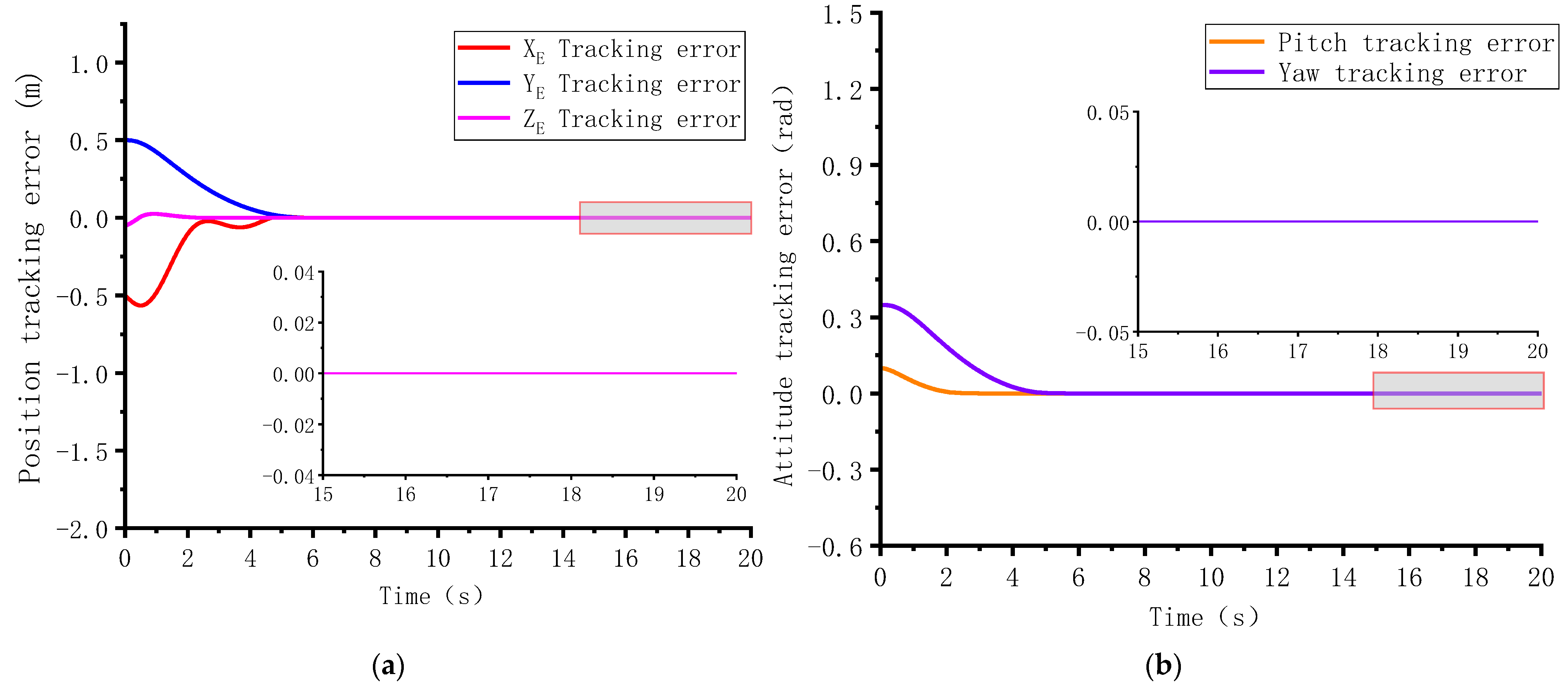
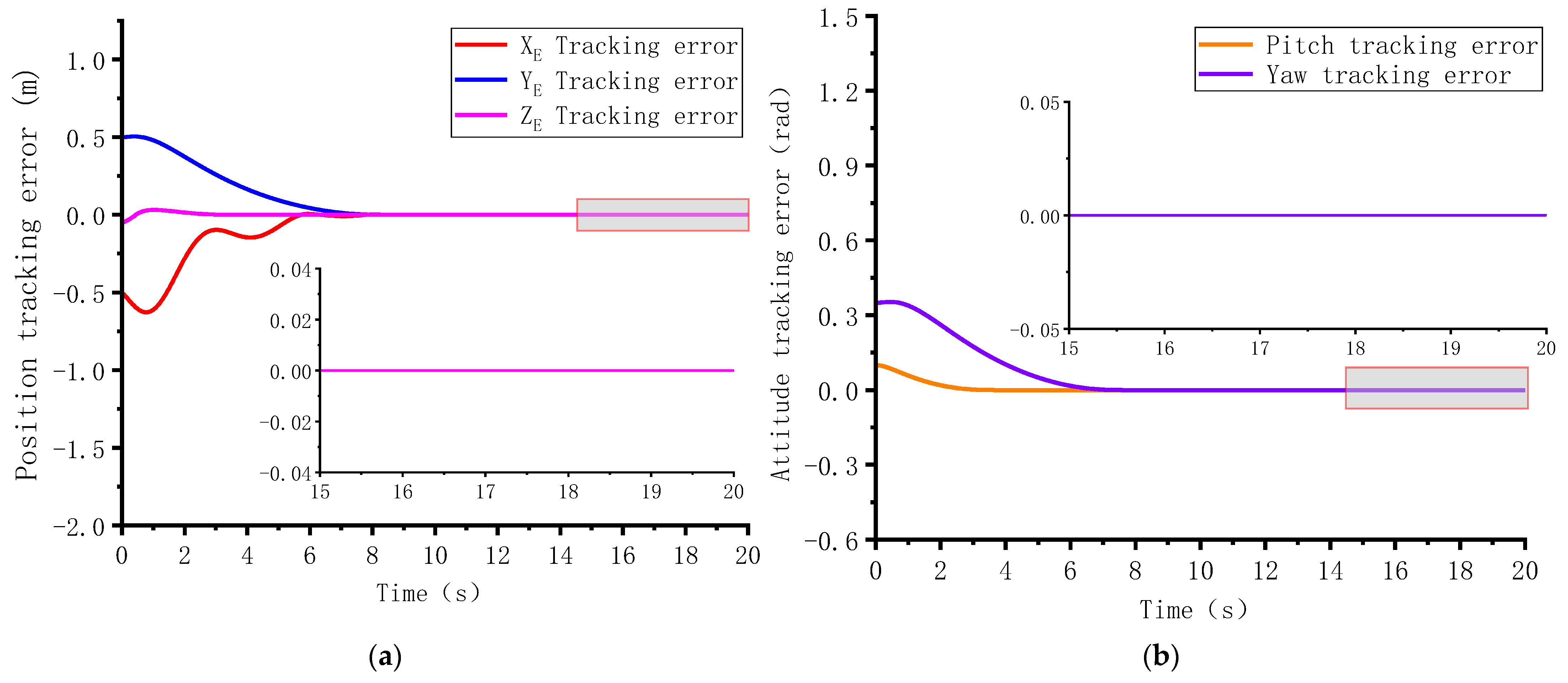
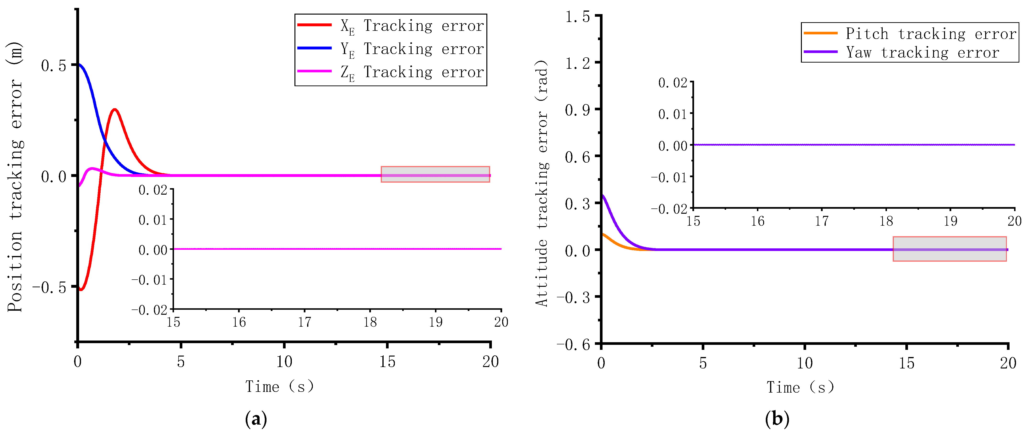
First, the trajectory tracking control is simulated with the predefined-time control law in Equation (25). The tunable parameters of the predefined-time observer and controller are set as:  k 1 = 1 , k 2 = 10 , k 3 = 5 , c 1 = 1 , T s = 10   s , T f = 5   s , p 1 = 7 / 13 , and  p 2 = 1 / 5 . The initial states of predefined-time disturbance observer in Equation (16) are all set as zeros. From the parameter setting, it can be found that the predefined convergence time is  T c = T s + T f = 15   s . With the predefined convergence time  T c , Figure 4 and Figure 5 show the simulation result of trajectory tracking error in different initial AUV states. It shows that the AUV position and attitude tracking error both converge to zero within 15 s in the two different initial states.
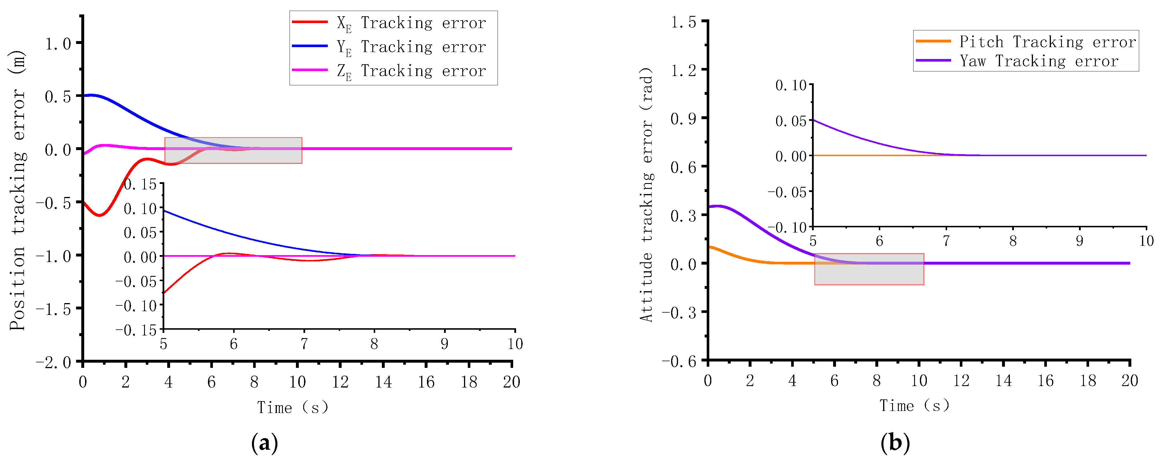
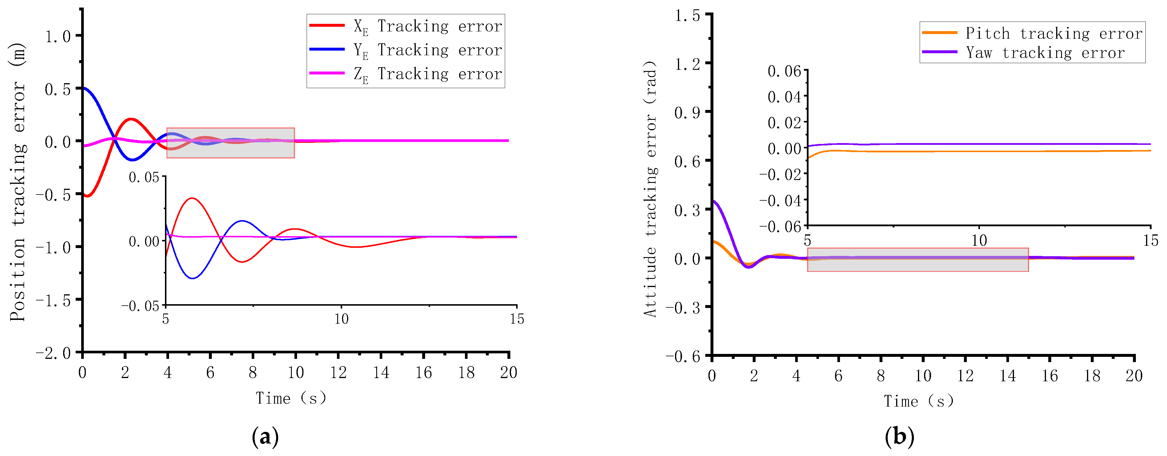
Then, keep the other control parameters unchanged and only modify the predefined time  T c  from  T c = 15   s  to  T c = 20   s . The modification in the predefined time will illustrate the adjustable time parameter’s influence on the convergence of the tracking error. The simulation result with the initial condition 1  η 1 ( t 0 )  is shown in Figure 6. Comparing the trajectory tracking errors in Figure 4 and Figure 6, it can be concluded that the convergence for  T c = 20   s  has a larger settling time than  T c = 15   s . This implies that the upper boundary of the settling time can be changed only by modifying  T c .
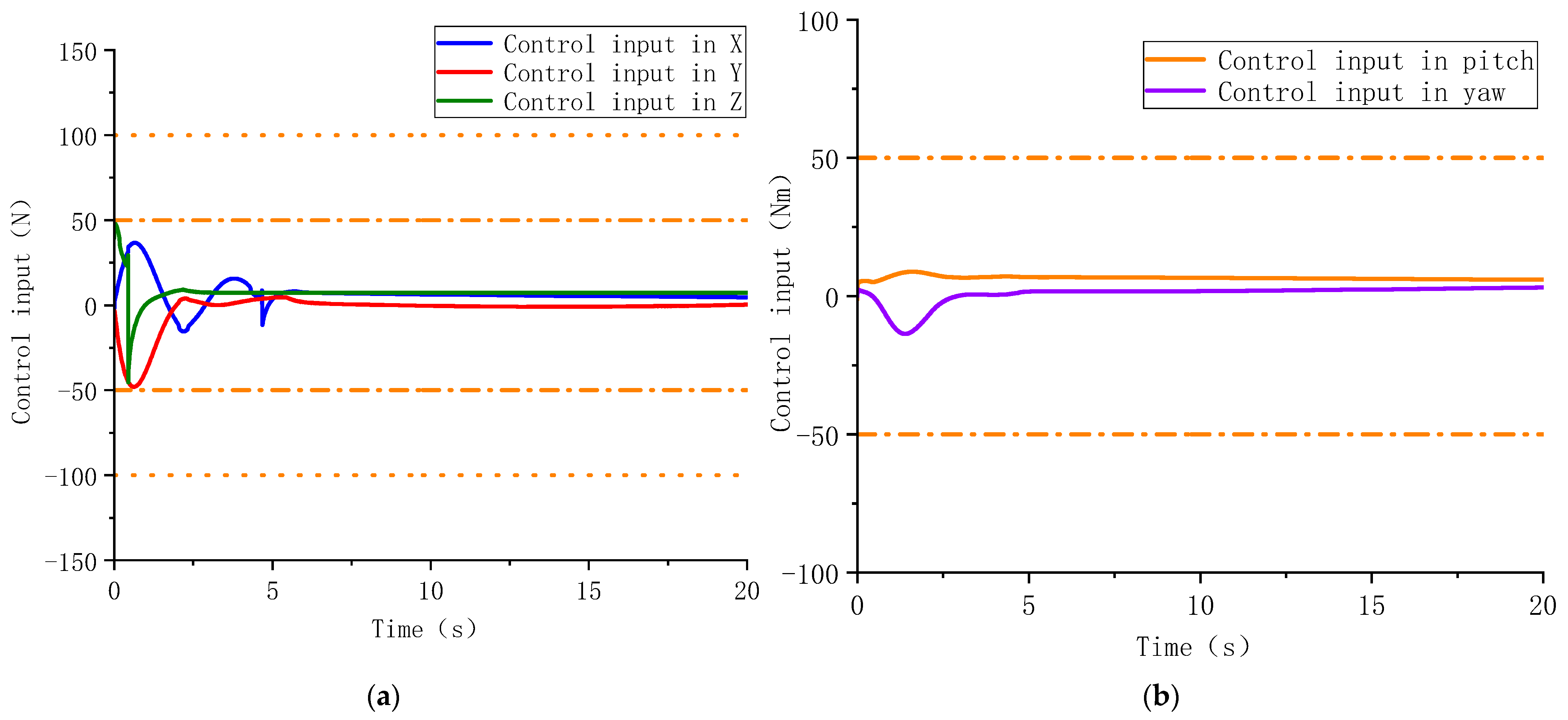
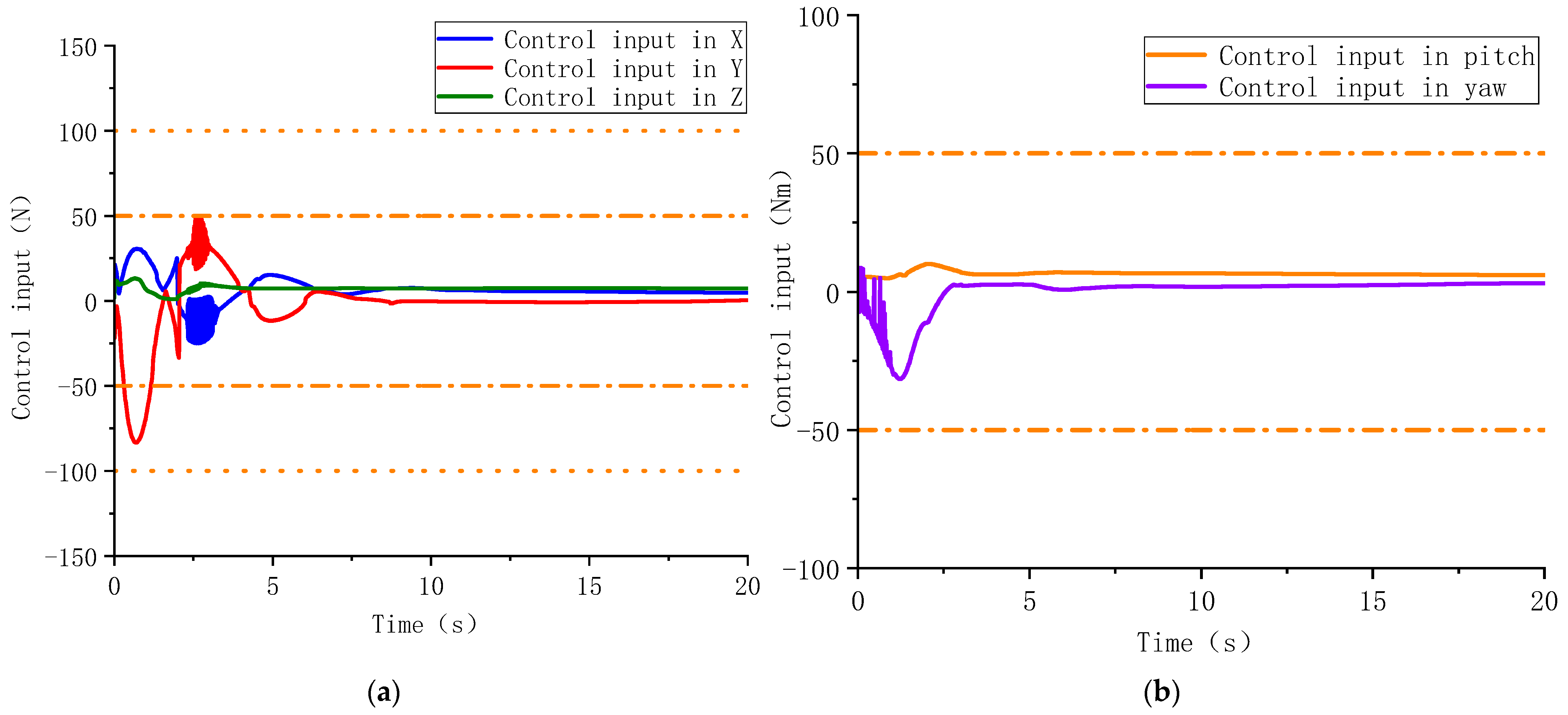
Subsequently, in order to analyze the influence of the control force and control moment, the change in the control input is shown in Figure 7. Figure 7 shows that the output forces and moments provided by the proposed controller are both constrained by the actuator’s physical limitations.
Then, the trajectory tracking error and the control input without the auxiliary system are presented in Figure 8 and Figure 9. Figure 8 shows that the trajectory tracking object can be achieved without considering the actuator saturation constraints. However, Figure 9 shows that the control input exceeds the physical limitation of the actuators. This is not suitable for the practical application of the AUV. The performance of the predefined-time control architecture is validated in the simulations.

4.2. Case 2: Disturbance-Observer-Based Practical Predefined-Time Control

In this section, the performance of the nonsingular, practical, predefined-time controller is illustrated. The tunable parameters of the controller are set as  T 1 = 0.1 , c 1 = 1 , c 2 = 1 , k χ 2 = 2 , ω 1 = 0.001 , and  ω 2 = 0.001 . In order to choose a similar convergence time to the predefined time controller in Equation (45), the predefined convergence time is chosen as  T c 1 = 15 / 2   s . Applying Lemma 2, we can obtain that the practical convergence time is  T c = 15   s . Then, Figure 10 shows the simulation result of the trajectory tracking error with predefined time  T c = 15   s .
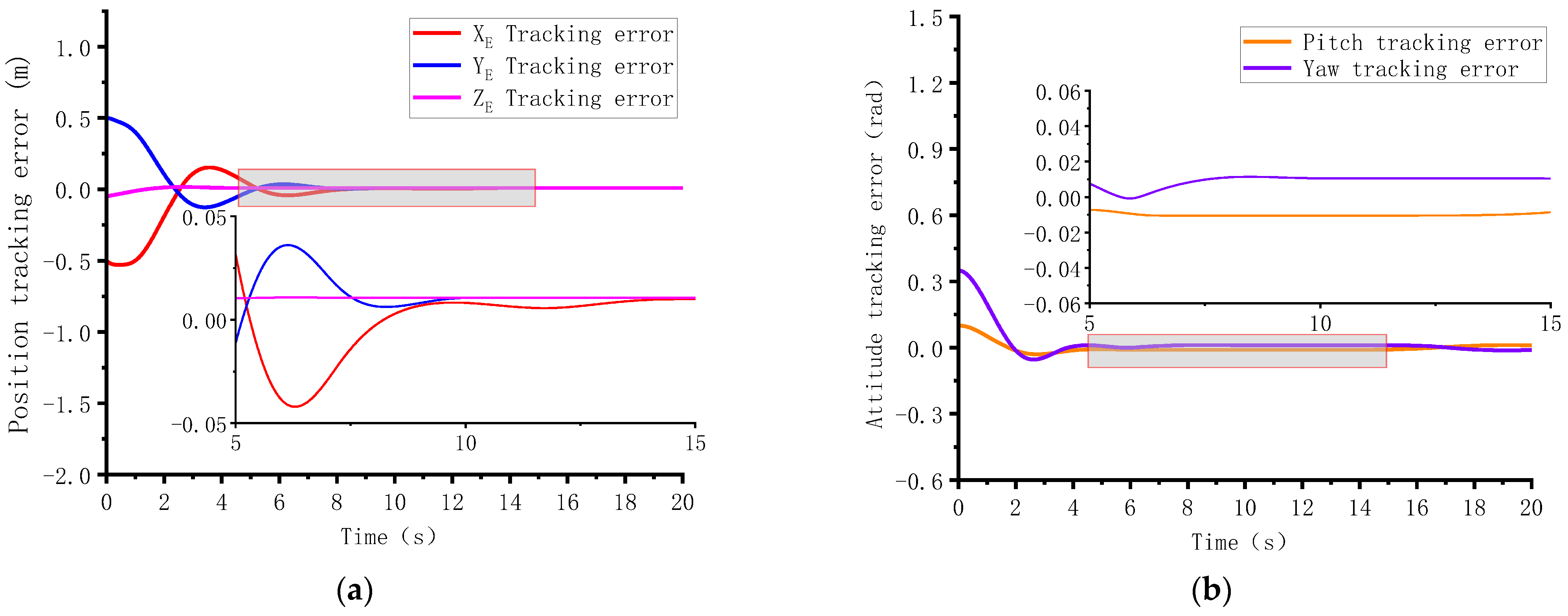
It can be found from Figure 10 that the non-singular controller guarantees the trajectory tracking error convergence within the practical convergence time is  T c = 15   s . Then, with other control parameters unchanged, modify only the predefined time  T c  from  T c = 15   s  to  T c = 20   s  to verify the influence of the adjustable time parameter on the convergence of the tracking error. From Figure 10 and Figure 11, it can be concluded that the trajectory tracking error for  T c = 20   s  has a larger settling time. This implies that the upper boundary of the settling time can be changed only by modifying  T c 1 .
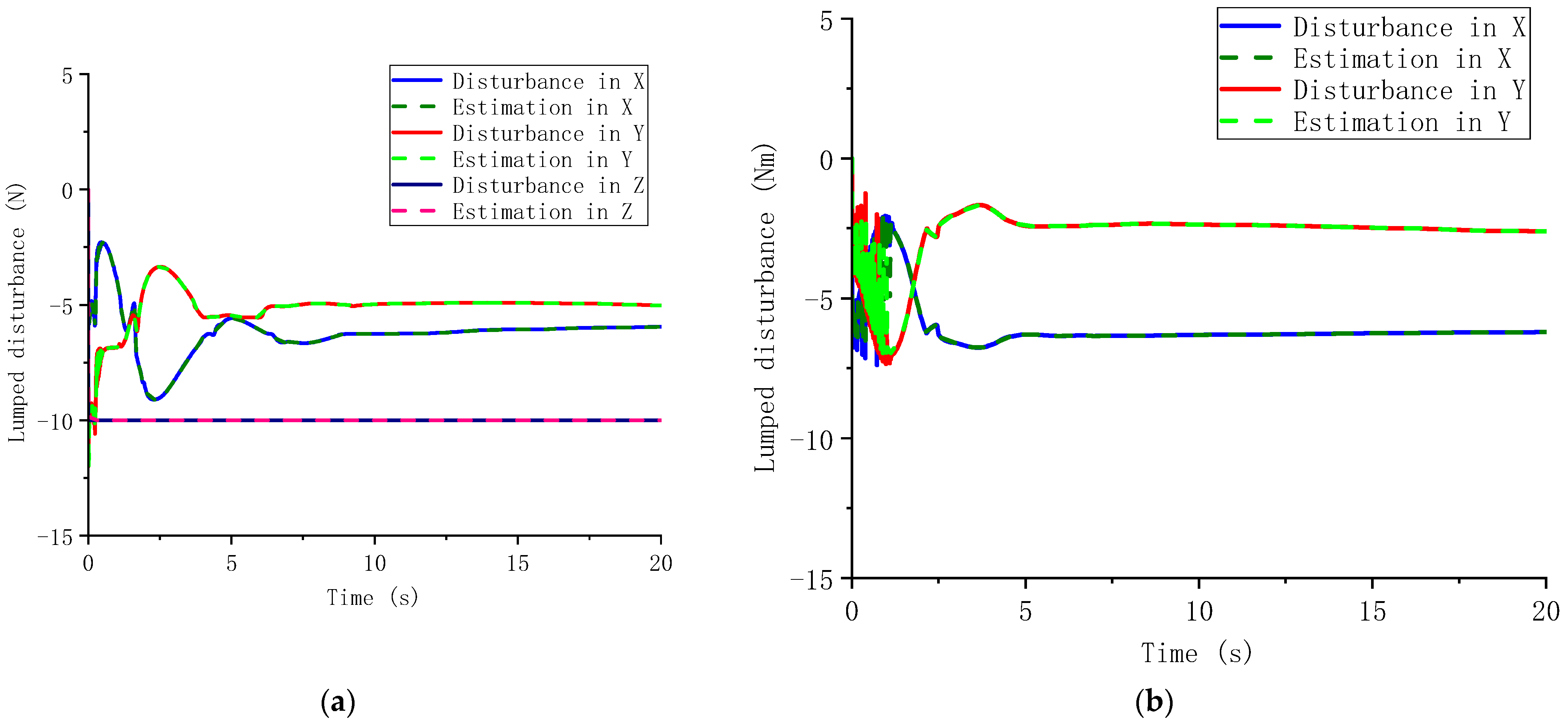
Then, Figure 12 continues to show the control input of the nonsingular backstepping method. Compared with Figure 7, there exists chattering at the beginning of the trajectory tracking process. The chattering phenomenon is influenced by the selection of predefined time  T c 1  and  T c 2  and the positive constants  ω 1  and  ω 2  in the virtual control input and the actual control input. A shorter predefined time and smaller value in the selection of  ω 1  and  ω 2  will increase the chattering phenomenon. Finally, Figure 13 shows that the predefined-time observer in Equation (16) reconstructs the lumped disturbance within the predefined time. The reconstructed lumped disturbance provides the compensation term for the predefined-time controller.
Nonetheless, the conservatism of this predefined time approach still persists. To demonstrate the conservatism in the proposed method, we can compare the convergence set obtained from Theorem 4 with the simulation result under the condition  T c = 15   s . The theoretical bound of the states is 0.038, as calculated from Theorem 4 using  ω 1 = ω 2 = 0.001 . However, in the simulation, in the trajectory tracking result shows that the actual boundary of the convergence set is lower than the analytical set. This suggests that the theoretical convergence set exhibits conservatism. The conservatism of the analysis results arises from the fact that the theoretical calculation process is based on information from different degrees of freedom, while the simulation results are observed separately. Additionally, the theoretical boundary depends on the unknown scalar  α 1 c , which is related to the virtual control law. Apart from a large value at the initial time, the unknown scalar remains close to zero. For these reasons, it can be concluded that some conservatism remains in the predefined boundaries at the predefined time.

5. Conclusions

In this paper, we developed two predefined-time active fault-tolerant controllers for the trajectory tracking of AUVs without violating the actuator’s physical limitations. We first designed a predefined-time sliding mode controller based on a predefined-time disturbance observer by incorporating a novel predefined-time auxiliary system to address actuator saturation constraints. Subsequently, a non-singular backstepping controller was developed to circumvent potential singularities in the sliding mode controller, guaranteeing that the trajectory tracking error converges within the predefined time. Simulation results were presented to demonstrate the effectiveness of the proposed architecture. Future research may explore the use of variable exponent coefficients in predefined-time controller to achieve zero-error predefined-time tracking with non-singular properties.

Author Contributions

Conceptualization, validation, and formal analysis, J.H.; project administrations, Y.L. (Ye Li); funding acquisition, Y.L. (Ye Li) and Q.Z.; writing—original draft, J.H.; supervision, Q.Z.; software, W.Z. and Y.L. (Yanying Li); data curation, writing—review and editing, Y.L. (Yanying Li). All authors have read and agreed to the published version of the manuscript.

Funding

This research was funded by the National Natural Science Foundation of China under Grants U1806228 and 51879057.

Data Availability Statement

Not applicable.

Conflicts of Interest

The authors declare no conflict of interest.

References

  1. Editorial, G. Emerging Trends in LPV-Based Control of Intelligent Automotive Systems. IET Control. Theory Appl. 2020, 14, 2715–2716. [Google Scholar] [CrossRef]
  2. Ali, N.; Tawiah, I.; Zhang, W. Finite-time extended state observer based nonsingular fast terminal sliding mode control of autonomous underwater vehicles. Ocean. Eng. 2020, 218, 108179. [Google Scholar] [CrossRef]
  3. Liu, X.; Zhang, M.; Chen, J.; Yin, B. Trajectory tracking with quaternion-based attitude representation for autonomous underwater vehicle based on terminal sliding mode control. Appl. Ocean Res. 2020, 104, 102342. [Google Scholar] [CrossRef]
  4. Sun, H.; Zong, G.; Cui, J.; Shi, K. Fixed-time sliding mode output feedback tracking control for autonomous underwater vehicle with prescribed performance constraint. Ocean Eng. 2022, 247, 110673. [Google Scholar] [CrossRef]
  5. Huang, B.; Zhou, B.; Zhang, S.; Zhu, C. Adaptive prescribed performance tracking control for underactuated autonomous underwater vehicles with input quantization. Ocean Eng. 2021, 221, 108549. [Google Scholar] [CrossRef]
  6. Zhou, B.; Su, Y.; Huang, B.; Wang, W.; Zhang, E. Trajectory tracking control for autonomous underwater vehicles under quantized state feedback and ocean disturbances. Ocean Eng. 2022, 256, 111500. [Google Scholar] [CrossRef]
  7. Gan, W.; Zhu, D.; Ji, D. QPSO-model predictive control-based approach to dynamic trajectory tracking control for unmanned underwater vehicles. Ocean Eng. 2018, 158, 208–220. [Google Scholar] [CrossRef]
  8. Sedaghati, S.; Abdollahi, F.; Khorasani, K. Model predictive and non-cooperative dynamic game fault recovery control strategies for a network of unmanned underwater vehicles. Int. J. Control. 2019, 92, 489–517. [Google Scholar] [CrossRef]
  9. Han, L.; Tang, G.; Cheng, M.; Huang, H.; Xie, D. Adaptive Nonsingular Fast Terminal Sliding Mode Tracking Control for an Underwater Vehicle-Manipulator System with Extended State Observer. J. Mar. Sci. Eng. 2021, 9, 501. [Google Scholar] [CrossRef]
  10. Li, J.; Du, J.; Zhu, G.; Lewis, F.L. Simple adaptive trajectory tracking control of underactuated autonomous underwater vehicles under LOS range and angle constraints. IET Control. Theory Appl. 2020, 14, 283–290. [Google Scholar] [CrossRef]
  11. Xu, R.; Tang, G.; Huang, D.; Xie, D.; Han, L. Adaptive fault-tolerant attitude control for a CMG-based underwater vehicle. J. Mar. Sci. Technol. 2020, 25, 800–807. [Google Scholar] [CrossRef]
  12. Liu, X.; Zhang, M.; Rogers, E. Trajectory Tracking Control for Autonomous Underwater Vehicles Based on Fuzzy Re-Planning of a Local Desired Trajectory. IEEE Trans. Veh. Technol. 2019, 68, 11657–11667. [Google Scholar] [CrossRef]
  13. Wang, X.; Tan, C.P. Dynamic Output Feedback Fault Tolerant Control for Unmanned Underwater Vehicles. IEEE Trans. Veh. Technol. 2020, 69, 3693–3702. [Google Scholar] [CrossRef]
  14. Xiang, X.; Yu, C.; Zhang, Q. On intelligent risk analysis and critical decision of underwater robotic vehicle. Ocean Eng. 2017, 140, 453–465. [Google Scholar] [CrossRef]
  15. Liu, X.; Zhang, M.; Wang, S. Adaptive region tracking control with prescribed transient performance for autonomous underwater vehicle with thruster fault. Ocean Eng. 2020, 196, 106804. [Google Scholar] [CrossRef]
  16. Qin, H.; Wu, Z.; Sun, Y.; Chen, H. Disturbance-Observer-Based Prescribed Performance Fault-Tolerant Trajectory Tracking Control for Ocean Bottom Flying Node. IEEE Access 2019, 7, 49004–49013. [Google Scholar] [CrossRef]
  17. Hu, Q.; Shao, X.; Chen, W.-H. Robust Fault-Tolerant Tracking Control for Spacecraft Proximity Operations Using Time-Varying Sliding Mode. IEEE Trans. Aerosp. Electron. Syst. 2018, 54, 2–17. [Google Scholar] [CrossRef] [Green Version]
  18. Fang, X.; Fan, H.; Wang, W.; Liu, L.; Wang, B.; Cheng, Z. Adaptive Finite-Time Fault-Tolerant Control of Uncertain Systems With Input Saturation. IEEE Trans. Syst. Man Cybern. Syst. 2022, 165–177. [Google Scholar] [CrossRef]
  19. Hao, L.-Y.; Yu, Y.; Li, H. Fault tolerant control of UMV based on sliding mode output feedback. Appl. Math. Comput. 2019, 359, 433–455. [Google Scholar] [CrossRef]
  20. Qin, H.; Chen, H.; Sun, Y. Distributed finite-time fault-tolerant containment control for multiple ocean bottom flying nodes. J. Frankl. Inst. Eng. Appl. Math. 2020, 357, 11242–11264. [Google Scholar] [CrossRef]
  21. Liu, F.; Tang, H.; Qin, Y.; Duan, C.; Luo, J.; Pu, H. Review on fault diagnosis of unmanned underwater vehicles. Ocean Eng. 2022, 243, 110290. [Google Scholar] [CrossRef]
  22. Merrill, W.C.; DeLaat, J.C.; Bruton, W.M. Advanced detection, isolation, and accommodation of sensor failures-Real-time evaluation. J. Guid. Control. Dyn. 1988, 11, 517–526. [Google Scholar] [CrossRef] [Green Version]
  23. Lunze, J.; Richter, J.H. Reconfigurable Fault-tolerant Control: A Tutorial Introduction. Eur. J. Control. 2008, 14, 359–386. [Google Scholar] [CrossRef]
  24. Behzad, H.; Casavola, A.; Tedesco, F.; Ali Sadrnia, M.; Gagliardi, G. A Fault-Tolerant Sensor Reconciliation Scheme based on Self-Tuning LPV Observers. In Proceedings of the 15th International Conference on Informatics in Control, Automation and Robotics, Porto, Portugal, 29–31 July 2018; pp. 111–118. [Google Scholar]
  25. Kadiyam, J.; Parashar, A.; Mohan, S.; Deshmukh, D. Actuator fault-tolerant control study of an underwater robot with four rotatable thrusters. Ocean Eng. 2020, 197, 106929. [Google Scholar] [CrossRef]
  26. Liu, X.; Zhang, M.; Yao, F. Adaptive fault tolerant control and thruster fault reconstruction for autonomous underwater vehicle. Ocean Eng. 2018, 155, 10–23. [Google Scholar] [CrossRef]
  27. Wu, C.; Yan, J.; Shen, J.; Wu, X.; Xiao, B. Predefined-time attitude stabilization of receiver aircraft in aerial refueling. IEEE Trans. Circuits Syst. II 2021, 68, 3321–3325. [Google Scholar] [CrossRef]
  28. Wang, S.; Wang, Y. Prescribed-time Leader-following Control of Second-order Multi-agent Systems under Event-triggered Mechanism. In Proceedings of the 2021 China Automation Congress (CAC), Beijing, China, 22–24 October 2021; pp. 4205–4210. [Google Scholar]
  29. Gonzalez-Garcia, J.; Gomez-Espinosa, A.; Garcia-Valdovinos, L.G.; Salgado-Jimenez, T.; Cuan-Urquizo, E.; Escobedo Cabello, J.A. Experimental Validation of a Model-Free High-Order Sliding Mode Controller with Finite-Time Convergence for Trajectory Tracking of Autonomous Underwater Vehicles. Sensors 2022, 22, 488. [Google Scholar] [CrossRef]
  30. Zhu, C.; Zhang, E.; Li, J.; Huang, B.; Su, Y. Approximation-free appointed-time tracking control for marine surface vessel with actuator faults and input saturation. Ocean Eng. 2022, 245, 110468. [Google Scholar] [CrossRef]
  31. Liu, S.; Liu, Y.; Wang, N. Nonlinear disturbance observer-based backstepping finite-time sliding mode tracking control of underwater vehicles with system uncertainties and external disturbances. Nonlinear Dyn. 2017, 88, 465–476. [Google Scholar] [CrossRef]
  32. Bouteraa, Y.; Alattas, K.A.; Mobayen, S.; Golestani, M.; Ibrahim, A.; Tariq, U. Disturbance Observer-Based Tracking Controller for Uncertain Marine Surface Vessel. Actuators 2022, 11, 128. [Google Scholar] [CrossRef]
  33. Zhang, M.; Liu, X.; Yin, B.; Liu, W. Adaptive terminal sliding mode based thruster fault tolerant control for underwater vehicle in time-varying ocean currents. J. Frankl. Inst. 2015, 352, 4935–4961. [Google Scholar] [CrossRef]
  34. Xie, S.; Chen, Q. Adaptive Nonsingular Predefined-Time Control for Attitude Stabilization of Rigid Spacecrafts. IEEE Trans. Circuits Syst. II Express Briefs 2022, 69, 189–193. [Google Scholar] [CrossRef]
  35. Xie, T.; Li, Y.; Jiang, Y.; Pang, S.; Xu, X. Three-dimensional mobile docking control method of an underactuated autonomous underwater vehicle. Ocean Eng. 2022, 265, 112634. [Google Scholar] [CrossRef]
  36. Cao, Y.; Wen, C.; Song, Y. Prescribed performance control of strict-feedback systems under actuation saturation and output constraint via event-triggered approach. Int. J. Robust Nonlinear Control. 2019, 29, 6357–6373. [Google Scholar] [CrossRef]
  37. Qin, H.; Wu, Z.; Sun, Y.; Sun, Y. Prescribed performance adaptive fault-tolerant trajectory tracking control for an ocean bottom flying node. Int. J. Adv. Robot. Syst. 2019, 16, 1729881419841943. [Google Scholar] [CrossRef]
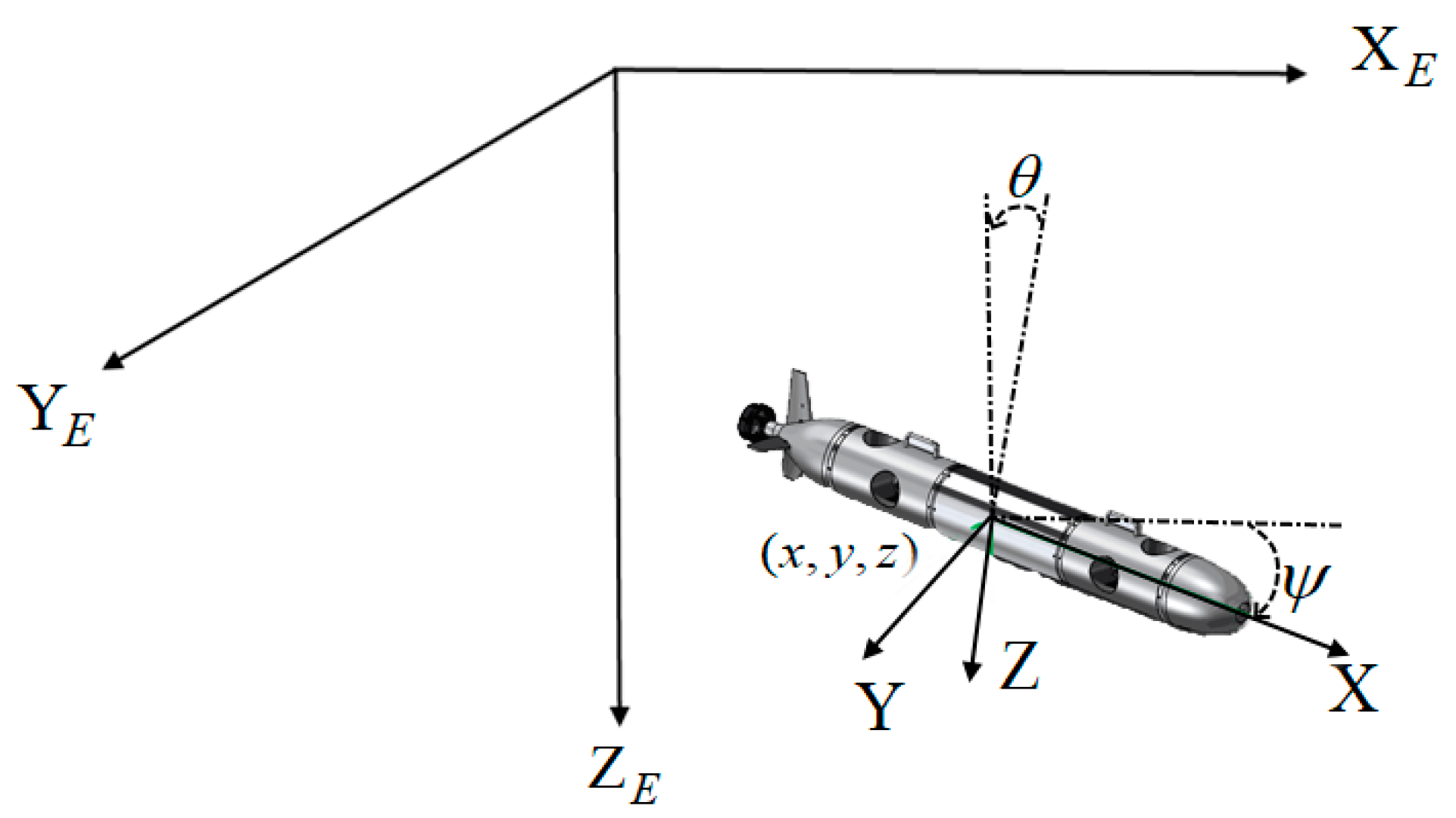
Figure 1. Motion coordinate frames and actuator configuration of the AUV model.
Actuators 12 00171 g001
Figure 2. Schematic of the proposed adaptive practical prescribed-time fault-tolerant control architecture for AUVs.
Actuators 12 00171 g002
Figure 3. Motion of the AUV trajectory tracking error ensured by the proposed predefined-time sliding mode controller in Equation (22).
Actuators 12 00171 g003
Figure 4. The AUV trajectory tracking result with predefined time as 15 s under initial condition 1: (a) AUV position tracking error; (b) AUV attitude tracking error.
Actuators 12 00171 g004
Figure 5. The AUV trajectory tracking result with predefined time as 15 s under initial condition 2: (a) AUV position tracking error; (b) AUV attitude tracking error.
Actuators 12 00171 g005
Figure 6. The AUV trajectory tracking result with predefined time as 15 s: (a) AUV position tracking error; (b) AUV attitude tracking error.
Actuators 12 00171 g006
Figure 7. Control input with auxiliary system with predefined time as 15 s under initial state 1: (a) Control force under initial state 1; (b) control moment under initial state 1.
Actuators 12 00171 g007
Figure 8. The AUV trajectory tracking result with predefined time as 15 s: (a) AUV position tracking error; (b) AUV attitude tracking error.
Actuators 12 00171 g008
Figure 9. Control input without auxiliary system with predefined time as 15 s under initial state 1: (a) Control force under initial state 1; (b) control moment under initial state 1.
Actuators 12 00171 g009
Figure 10. The AUV trajectory tracking result with predefined time as  T c 1 = 15 / 2   s  under initial condition 1: (a) AUV position tracking error; (b) AUV attitude tracking error.
Actuators 12 00171 g010
Figure 11. The AUV trajectory tracking result with predefined time as  T c 1 = 15 / 2   s  under initial condition 1: (a) AUV position tracking error; (b) AUV attitude tracking error.
Actuators 12 00171 g011
Figure 12. The AUV trajectory tracking result with predefined time as  T c 1 = 15 / 2   s  under initial condition 1: (a) AUV position tracking error; (b) AUV attitude tracking error.
Actuators 12 00171 g012
Figure 13. Lumped disturbance reconstruction with predefined-time observer in Equation (12): (a) Lumped disturbance forces reconstruction result; (b) lumped disturbance moments reconstruction result.
Actuators 12 00171 g013
Table 1. The inertial coefficient of AUV.
Parameter   M   I x x   I y y   I z z
Value30 kg0.1215 kgm25.468 kgm25.468 kgm2
Table 2. AUV partial hydrodynamic coefficients.
ParametersValueParametersValue
  X u ˙ −7.14 kg   Y v ˙ −67.7 kg
  X u −5.8 kg/s   Y v −49.15 kg/s
  X | u | u −9.29 kg/m   Y v | v | −79.71 kg/s
  Z w ˙ −60.63 kg   N r ˙ −0.48 kgm2
  Z w −49.52 kg/s   N r −0.56 kgm2/s
  Z | w | w −80.15 kg/m   N r | r | −115.06 kgm2
Disclaimer/Publisher’s Note: The statements, opinions and data contained in all publications are solely those of the individual author(s) and contributor(s) and not of MDPI and/or the editor(s). MDPI and/or the editor(s) disclaim responsibility for any injury to people or property resulting from any ideas, methods, instructions or products referred to in the content.