Article

A Study on the Design of Novel Slotless Motor Considering Winding Manufacture Process for a Collaborative Robot

1
Department of Electrical Engineering, Hanyang University, Seoul 04763, Republic of Korea
2
The Research Institute of Industrial Science, Hanyang University, Seoul 04763, Republic of Korea
3
Department of Mechanical, Automotive and Robot Engineering, Halla University, Wonju 26404, Republic of Korea
*
Author to whom correspondence should be addressed.
Actuators 2023, 12(4), 156; https://doi.org/10.3390/act12040156
Submission received: 5 March 2023 / Revised: 26 March 2023 / Accepted: 31 March 2023 / Published: 3 April 2023

Abstract

:
In this paper, the design of novel slotless permanent magnet synchronous motor (PMSM) for a collaborative robot was studied considering the manufacture process of winding. The winding manufacture process of novel slotless PMSM was proposed in three steps. First, the two types of coil units were manufactured based on the winding jig to assemble the coil units. Second, the coil unit was manufactured using the injection molding based on the plastic material such as polyphenylene sulfide (PPS). Third, the units of the coil were assembled to form a stator winding. Considering this manufacture process of winding, the slotless motor design was studied for the collaborative robot. For the design and analysis of slotless motor, finite element analysis (FEA) was performed through ANSYS Maxwell. The electromagnetic performance was analyzed according to the pole-slot combination. Considering the space of the collaborative robot, the basic model was designed. Based on the basic model, the electromagnetic performance was analyzed according to the design parameters such as the thickness of magnet and yoke and turns per slot. Considering the torque and current density, the final model was designed. To verify the FEA results, the slotless motor was manufactured and the experiment and FEA results were compared.

1. Introduction

In recent years, the collaborative robot became an important part of the industrial automation. Collaborative robots help increase productivity on assembly lines by performing repetitive and dangerous tasks for workers. Due to this advantage, research on collaborative robots was actively conducted over the past few decades, and the global market size expanded. The global market for collaborative robots is expected to grow from $981 million in 2020 to $7172 billion in 2026, and was reported to be steadily increasing at an average annual growth rate of about 41.2% [1,2,3]. The collaborative robot consists of an electric motor, controller, harmonic drive gear, and encoder [4,5]. Of the critical parts of the collaborative robot, the electric motor is considered the most important part since it is related to the high dynamics and miniaturization [6]. Therefore, the electric motor is required to have high torque density and efficiency. Permanent magnet synchronous motor (PMSM) with rare-earth permanent magnets (PMs) are widely used in the collaborative robot since rare-earth PMs are capable of the high torque density and miniaturization [7,8,9,10,11]. However, the collaborative robot requires low torque ripple and cogging torque because high precision control is required. Therefore, the reduction in torque ripple and cogging torque was studied [12,13,14,15,16].
The general motor adopts a slot structure to wind the coil. Since the slot structure has teeth, the magnetic gap length is short, which can have a high output density. However, there is a slot opening to wind up the coil, which makes the length of the airgap different depending on the rotor position. This creates a cogging torque, which causes torque ripple, causing vibration and noise and interfering with precise control of the motor [17,18,19,20]. Therefore, for motors requiring precise control such as for robots, various researchers studied how to reduce cogging torque [21,22,23]. However, these did not find how to completely eliminate the cogging torque. In order to completely remove the cogging torque, interest in slotless motors that is the absence of teeth is increasing in the field of high-precision robot motor. Furthermore, the slotless motor has the advantages of low torque ripple, low vibration and noise, which is advantageous in the field of high precision robot motor. Due to the zero-cogging characteristics, the slotless motors are capable of smooth operation [24]. Moreover, since there are no teeth, iron loss is very small, which is advantageous for ultra-high speed machines such as air propulsion [25,26,27]. However, since the coil cannot be wrapped and fixed in the absence of teeth, research on the slotless motor is difficult. The studied slotless motor mainly has a structure with axial type toroidal winding [27,28,29]. In addition, slotless motors with drum-type conventional windings have a standardized shape for arranging and fixing the windings [30,31,32]. Therefore, this paper proposes the new coil which has no fixed structure and can adopt conventional winding. Furthermore, design methods of proposed slotless motor are introduced.
In this paper, the design of the novel slotless motor is studied considering the manufacture process of coils for the collaborative robot. The coil was wound conventionally and coil forming was performed. By covering the surface of the formed coil with injection molding, it was made into a block shape that allowed each coil to be assembled. Although the proposed structure adopted conventional winding, it did not require a special shape for coil placement and fixation because it had a block structure that could be assembled. Therefore, it is possible to have a high freedom in designing a slotless motor through the proposed structure. The design constraints are defined considering the manufacture process of coils based on the forming coil and injection molding. Based on the design constraints, the finite-element analysis (FEA) model was proposed, and the performances of the slotless motor were analyzed according to the design parameters. First, the performance of the slotless motor according to the pole-slot combination were analyzed, and the basic model was designed considering the size constraints for the collaborative robot. Furthermore, the characteristics of the slotless motor were analyzed for shape variables to achieve the torque and voltage, and the final model was designed. The final model of the slotless motor was manufactured, and the experiment was performed to verify the FEA results.
This paper is organized as follows. In Section 2, the demands and specifications for the collaborative robot are introduced. In Section 3, the proposed slotless motor structure and manufacture process of winding are discussed. In Section 4, the design method is discussed considering the manufacture process of winding using FEA. In Section 5, to verify FEA results, the novel slotless motor is manufactured, and the experiment results are compared with the FEA results. Finally, Section 6 contains the conclusion.

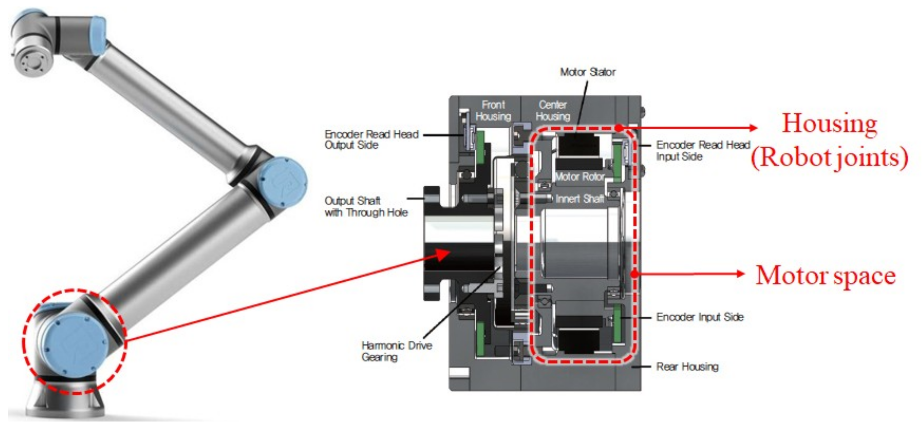
2. Specifications of Slotless Motor for the Collaborative Robot

Figure 1 shows the collaborative robot and the motor. The collaborative robot consists of the motor, controller, encoder, and the harmonic drive gearing. The motor space is limited by the various components. Therefore, when the motor is designed, the motor length including the stator end-winding must be considered for the collaborative robot. Table 1 shows the size constraints of the motor for the target collaborative robot. Since there is a constraint on the motor length including the end-winding, the design of slotless motor must consider the length of the end-winding and electromagnetic performance. Table 2 shows the rated condition of the motor for the collaborative robot. The rated power of motor was 1.1 kW, the rated speed of motor was 3400 rpm, and the DC-link voltage was 48 V. The torque was required as 3.3 Nm considering the margin. Considering the constraints of total motor length and current density, the slotless motor was designed.

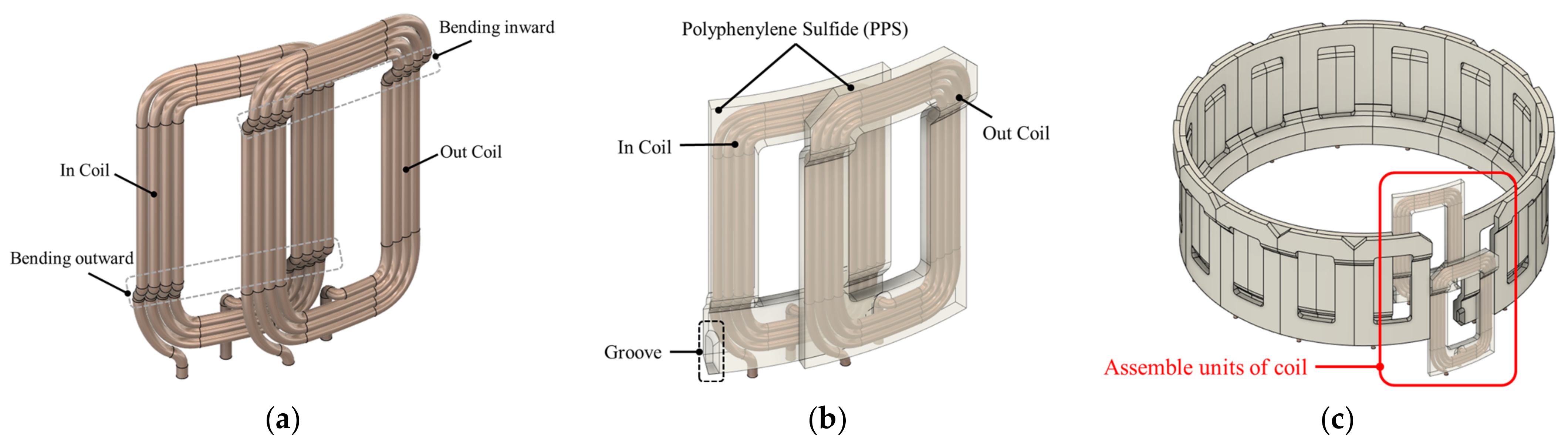
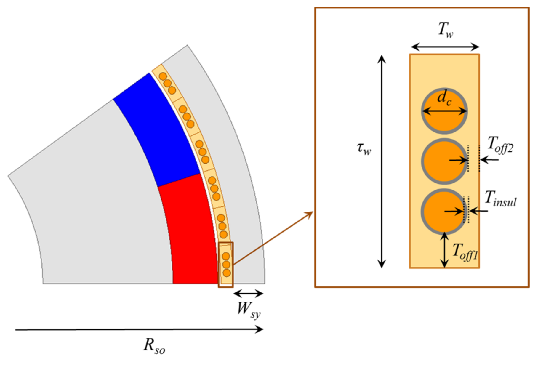
3. Structure and Manufacture Concept of the Novel Slotless Motor

Figure 2 shows the structure concept of the novel slotless motor. The manufacture process of the novel slotless motor was divided into three steps. Frist, the two types of coil (Out coil and In coil) were manufactured based on the winding jig to assemble the coil units as shown in Figure 2a. Slotless motors are advantageous in that the length of the magnetic gap is as short as possible due to the absence of teeth. Therefore, as shown in Figure 2a, it was designed as a one layer. In addition, to form a coil with a concentric winding, it is necessary to model the terminals so that they do not overlap. For the two types of coil shapes, it is necessary to select pressure considering the elongation rate of the conductor because the coil can break when bent. Second, the coil units were manufactured using the injection molding based on the plastic material such as polyphenylene sulfide (PPS) as shown in Figure 2b. The injection molding material should cover the entire surface of the coil so that the coil can be fixed. Therefore, a small margin between the coil and injection molding material must be considered, so that the injection molding material can cover all the coil’s surface. In the bottom of Figure 2b, there is a groove for terminal processing of the coil. Therefore, when designing the winding, a larger margin was selected on both sides of the coil. Therefore, as will be explained later, when designing the electromagnetic field, the coil diameter and number of turns should be selected in consideration of this margin. Third, the units of the coil were assembled to form a stator winding as shown in Figure 2c. Due to this structure, it was possible to maintain the stator of slotless motor. As the two types of coils were bent in different directions, the side of one coil and the hollow part in the middle of the other coil were interlocked, enabling an assembly structure.
Figure 3 shows the FEA model and constraint of winding space considering the manufacture process of coils. As shown in Figure 3, the proposed slotless motor consisted of a rotor and stator iron (35PN230), permanent magnet (N45UH), coil (copper), and injection molding (PPS) covering the coil. In general motors, coil is wound on teeth, but a slotless motor does not have teeth, so the coil cannot be fixed using normal methods. Therefore, the proposed slotless coil was placed and fixed in the injection molding as mentioned above. For this, an injection molding was performed on the coil, and margin was given so that the injection molding material completely covered the coil surface. This margin affected the thickness of injection molding, number of turns, and coil diameter. Therefore, the slotless motor design considering the constraint of manufacture of coil is required, which will be explained in the next section.

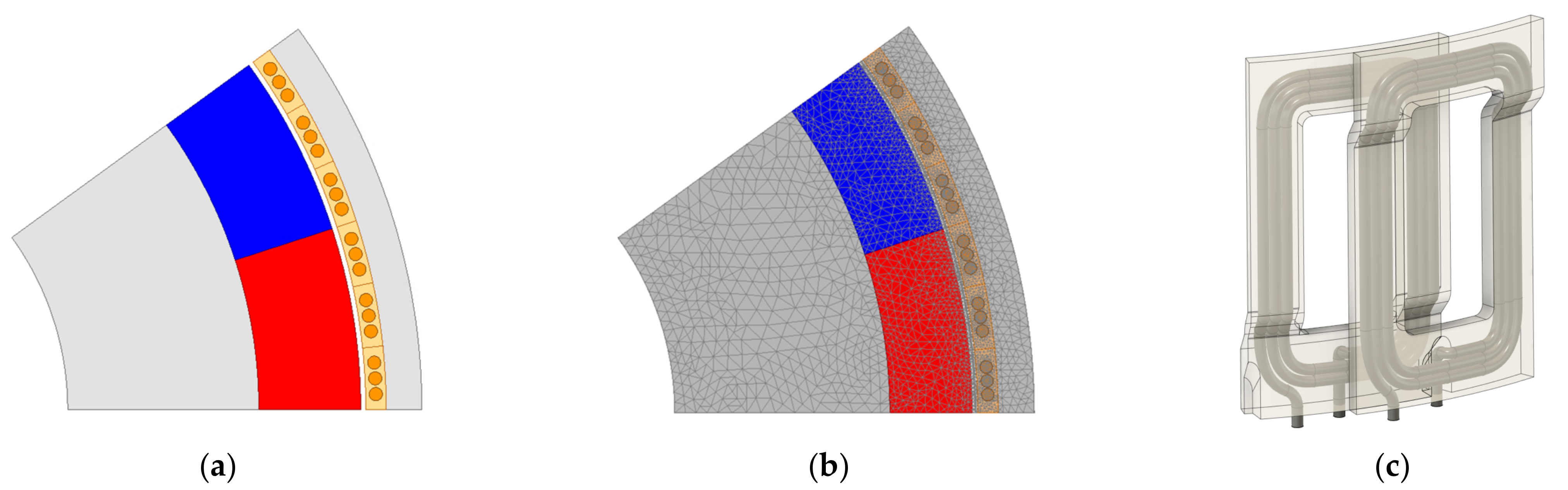
4. Design of Slotless Motor Considering the Proposed Manufacture Process

This section shows the electromagnetic design procedure of the proposed slotless motor. First, in order to satisfy the size constraints (especially the total motor length) and torque comparison, the pole slot combination was analyzed. When the pole slot combination was determined, the winding design was performed considering the torque, and design points were set by drawing contour according to the thickness of the permanent magnet and the width of the stator yoke.

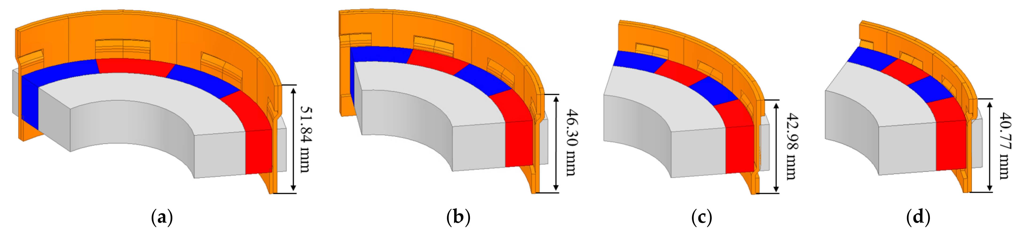
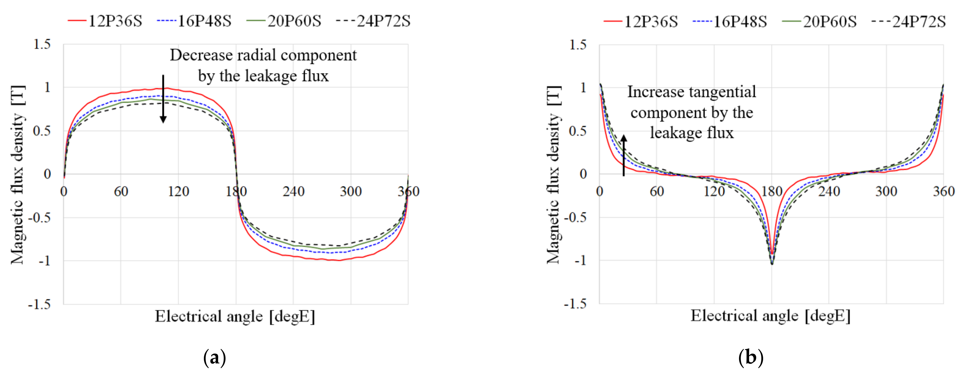
4.1. Pole Slot Combination

The proposed winding structure took the form of a block to satisfy the assembly structure. If a non-overlapping structure was selected, bonding work was required because each block was attached to the side. However, if the overlapping structure was selected as shown in Figure 2, each block can be interlocked, and so, it was possible to configure the winding only by assembling without the need for bonding. In the proposed coil structure, coils of one phase were arranged in one block. Since two coil edges with different phases were inserted into an empty space of one block, only one can be selected as the number of slots per pole per slot. Furthermore, three blocks compose one period, and in order to make the number of in coils and out coils the same, they must be composed of multiples of two period. Therefore, the number of pole-pairs must be even, and the total number of windings was designed to be six times the number of poles. To compare the characteristics for the pole slot combinations under the condition of the same total series turns, the number of turns in injection molding changes for pole slot combinations. Moreover, as mentioned above, the specifications such as winding and motor size change according to the number of turns. Therefore, the torque and total motor size according to the pole slot combination were analyzed. Figure 4 shows the analysis model according to the pole slot combination. In order to assume the same conditions, the total number of series turns and stack length were selected. Table 3 shows the characteristics of each analysis model for pole slot combination, and Figure 5 shows the radial and tangential magnetic flux density according to pole slot combination. As the number of pole increased, the torque decreased due to the increase in leakage flux between near poles appearing as decreasing the radial flux and increasing the tangential flux, as shown in Figure 5. Moreover, the larger number of slot, the fewer the number of turns in one block, and total motor length was smaller, as shown in Table 3. Considering the constraints of size in Table 1, 20P60S was selected as the basic model.

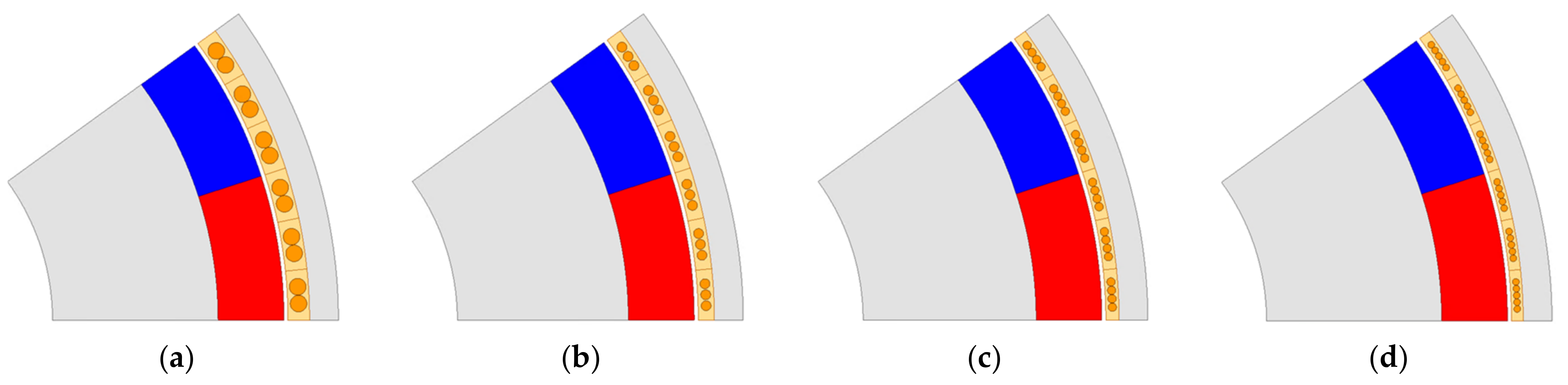
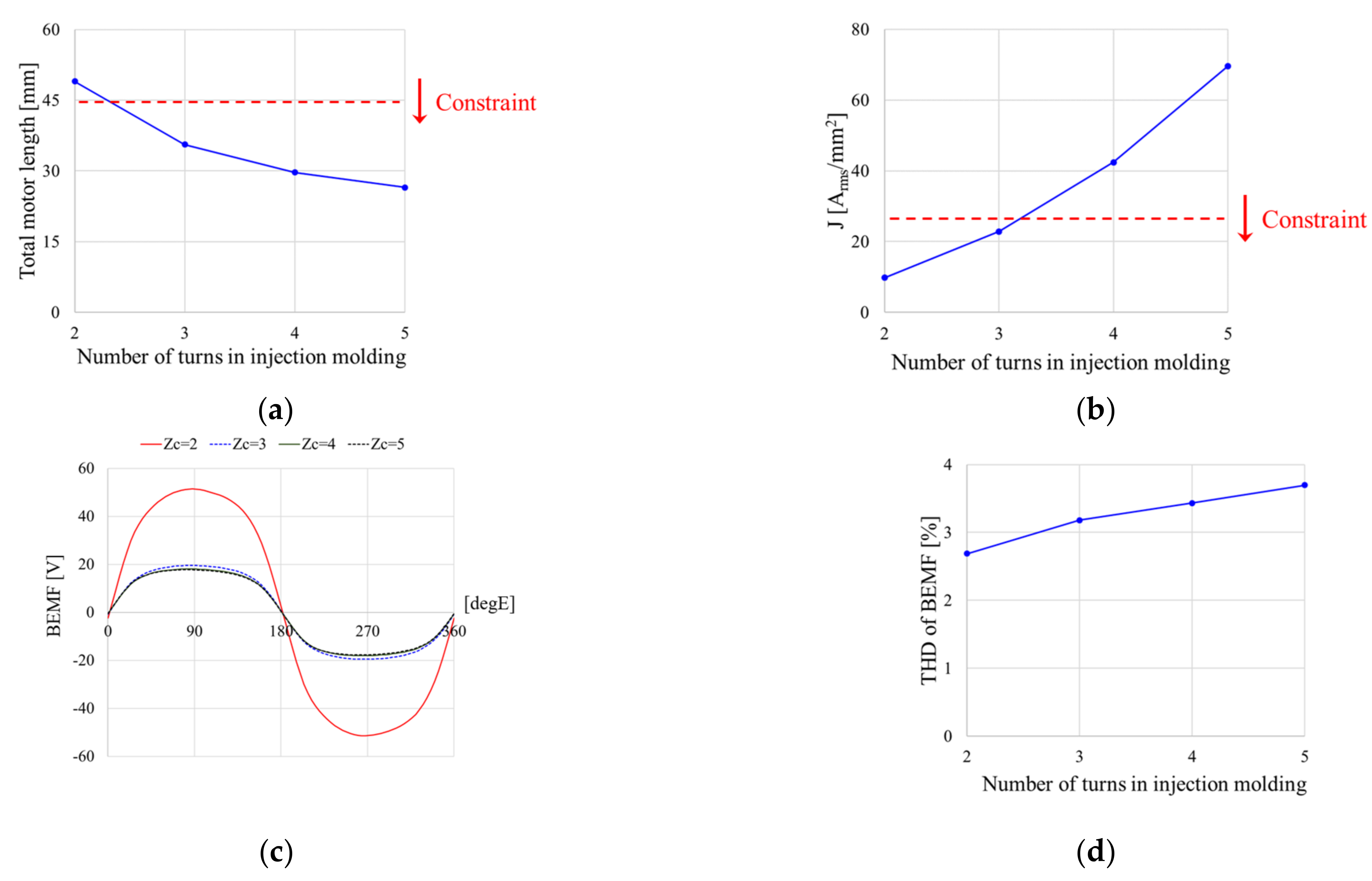
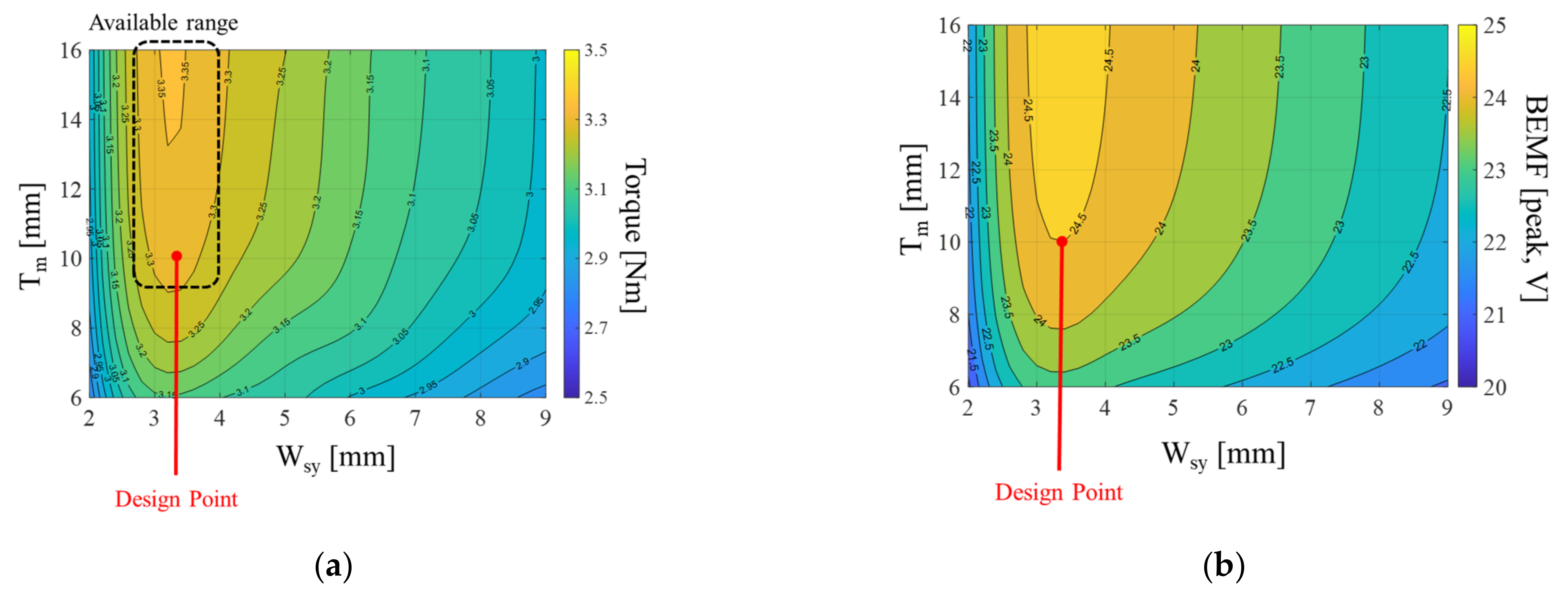
4.2. Design of Slotless Motor Considering Constraints of Winding Manufacture

Figure 6 shows the geometry parameters. The thickness of injection molding can be expressed through the sum of coil diameter, thickness of insulation, and minimum thickness for the injection. The width of injection molding can be expressed as the relationship between the number of conductors and the minimum thickness of injection molding, and slot pitch. Considering the winding constraints in Figure 3, the relationships of the geometry are expressed as follows.
T w = d c + 2 T i n s u l + 2 T o f f 1
τ w = Z c d c + 2 Z c T i n s u l + 2 T o f f 2
τ w = π N s l o t R s o W s y T w 2
where Tw is the thickness of injection molding, dc is the coil diameter, Tinsul is the thickness of the insulation, Toff1 and Toff2 are the minimum thickness for the injection molding, Zc is the number of turns in injection molding, τw is the width of injection molding, Nslot is the number of slot, Rso is the outer radius of stator, and Wsy is the width of stator yoke.
From Equations (1)–(3), the thickness of injection molding is expressed as follows.
T w = 2 π N s l o t R s o W s y + 2 Z c T i n s u l + 2 T o f f 1 Z c 2 T o f f 2 Z c + π N s l o t
The thickness for the injection molding must satisfy 0.3 mm for Toff1 and 1.0 mm for Toff2 as shown Figure 3. Figure 7 shows the FEA models according to the number of turns through Equation (4). As the number of turns in injection molding increased, the thickness of winding decreased from Equation (4). To compare the characteristics of models under the same condition of the torque, the stack length was adjusted according to the number of turns. Figure 8 shows the characteristics according to the number of turns. As the number of turns increased, the total motor length decreased due to the decrease in stack length. As a result, the model with a low number of turns tended to have a high BEMF due to a large stack length. Furthermore, the THD of the BEMF decreased according to the number of turns and stack length. However, since the diameter of coil decreased as the number of turns increased, the current density that was related with operating temperature increased. Therefore, considering the constraints of the total motor length and current density in Table 1 and Table 2, the number of turn was designed as three in Figure 7b.
To improve the torque, the characteristic maps according to the design parameters (Tm and Wsy in Figure 6) are analyzed. Figure 9a shows the torque for the design parameters. As the thickness of magnet increased, the torque can increase since the magnetic flux density increased. However, since the magnetic flux density was saturated as the thickness of magnet increase, the amount of increase in the torque according to the thickness of the permanent magnet decreased. Since the magnetic flux density in the stator yoke decreased as the width of the stator yoke increased, the reluctance of the stator yoke decreased and the torque can increase. However, because the rotor diameter also decreased, the flux per poles decreased and the torque decreased. Figure 9b shows BEMF for the design parameters. The characteristics of BEMF for the design parameters appear to be almost similar to those of the torque since the power factor was almost in unity in the slotless motor. Considering magnetizable thickness of permanent magnet and manufacturable width of the stator yoke, the design parameters were selected as Tm = 10 mm and Wsy = 3 mm.

4.3. Final Model of Slotless Motor

For the model designed through the previous section, Figure 10a shows the final 2D-FEA model using ANSYS Maxwell, and Figure 10b shows the mesh plot. For analysis, the memory was required up to 200 MB. The number of total meshes was 9545. In order to accurately consider the copper loss in coil, the mesh of coil was subdivided as shown in Figure 10b. Figure 10c shows the units of coil obtained through the process described above subsection. Figure 11 shows the flux density and flux line distribution. Table 4 shows the analysis results of designed model. In Table 4, it can be confirmed that all components satisfied the constraints of Table 1 and Table 2. Furthermore, due to the characteristics of the slotless motor without teeth, cogging torque did not appear.

5. Manufacture and Experiment Verification

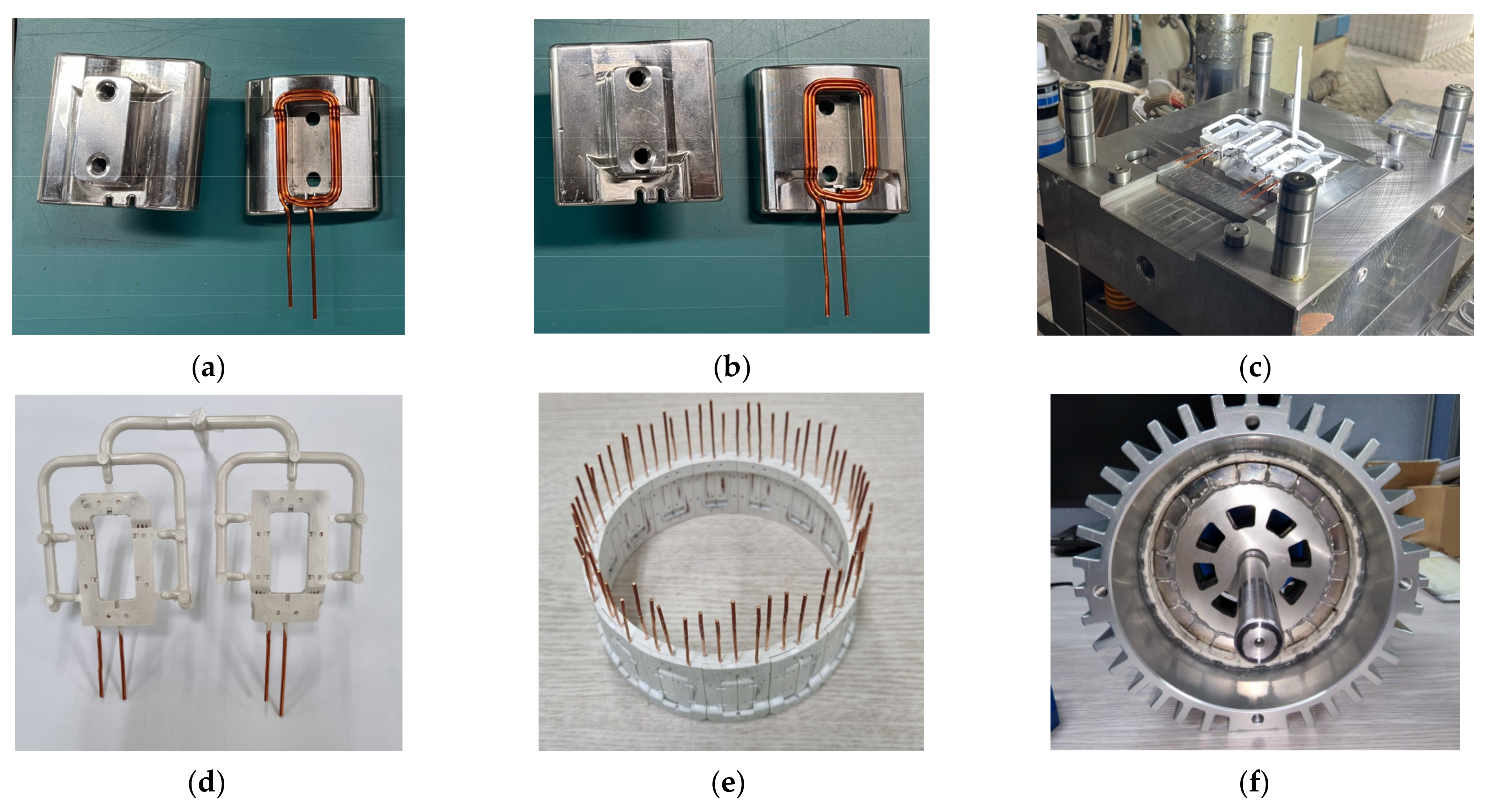
5.1. Manufacture of Slotless Motor

Figure 12 shows the manufacture process of the novel slotless motor. First, coil was wound according to the number of turns. In Figure 12a,b, wound coils are placed into the forming mold and pressure was applied in coils. After completing the forming of the coil, the coil was placed into the injection mold, as shown in Figure 12c, for injection molding. By covering the surface of coil with an injection molding material to form a block structure, a unit of coil, as shown in Figure 12d, can be obtained. The stator was assembled by combining the units of coil as shown in Figure 12e. Finally, the stator, rotor, and housing were assembled, and a novel slotless motor can be obtained as shown in Figure 12f.

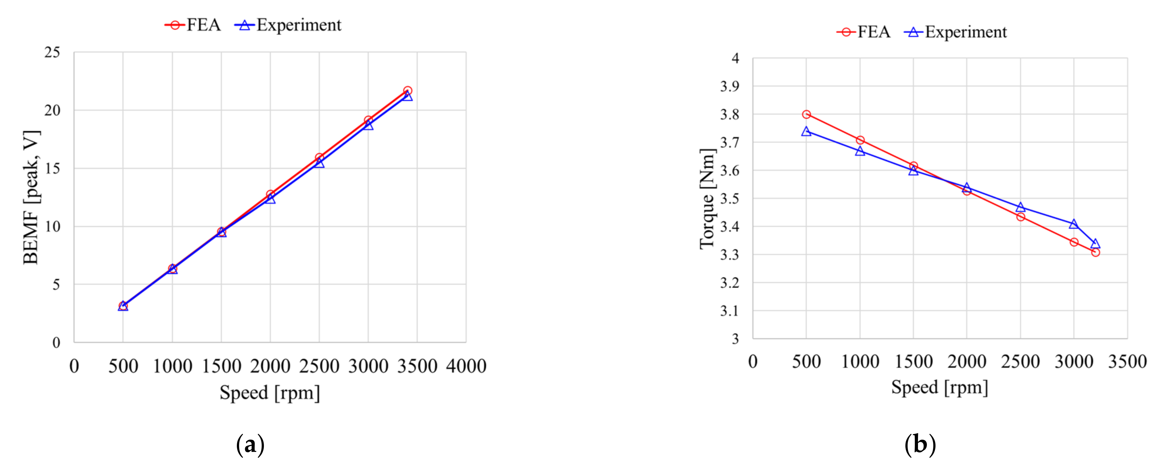
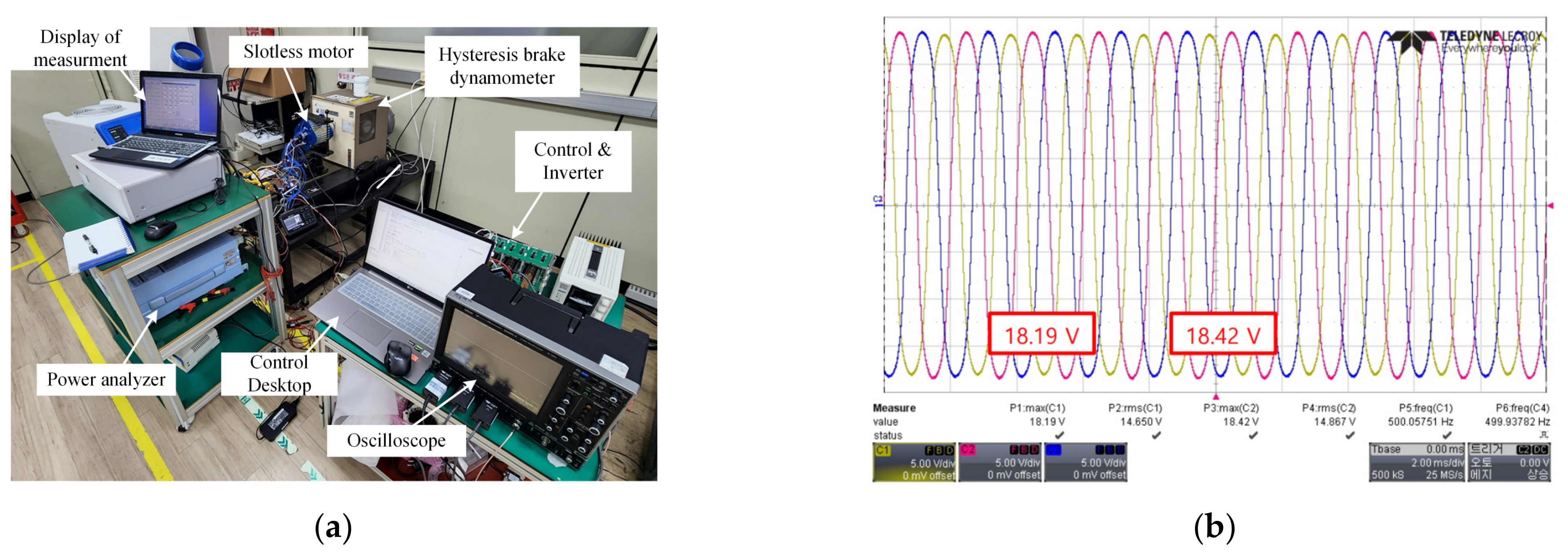
5.2. Experiment Verification

To verify FEA results, an experiment was conducted to verify the manufactured slotless motor. Figure 13a shows the experiment environment, and Figure 13b shows the BEMF waveform when the rotor speed was 3000 rpm. In Figure 13b, three-phase BEMF waveform was unbalanced since the position of the coil was distorted a little during forming and injection of the coil. However, it can be solved by increasing the precision of manufacturing and coil arrangement. Figure 14a shows the comparison with FEA and experiment results of the BEMF according to the speed under the condition of no-load, and Figure 14b shows the analysis and experiment results of the torque according to the speed when the rated current was 28.5 Arms. Although there were errors between the results of the analysis and the experiment in Figure 13, the error was within 3%. As a result, FEA results were verified comparing with the experiment results.

6. Conclusions

In this paper, the design process of novel slotless motor was proposed considering the manufacture process of coil for the collaborative robot. The novel slotless structure covered the coil with an injection molding material, which imposed design constraints on the coil diameter and the number of turns. Considering the design constraints, an FEA model was designed and the characteristics of motor were analyzed. First, the characteristics were analyzed according to the pole slot combination, and the basic model was designed considering the size constraints for the collaborative robot. Based on the basic model, the final model was made for the design parameters considering the constraints of manufacturing and positioning coil. The final model was derived using the proposed manufacture process, and the experiment was compared with FEA result to verify the effectiveness of slotless motor. This paper proved the novel slotless motor and manufacture process of coil. Furthermore, the performance of the novel slotless motor was verified for FEA and experiment results. Based on the manufacture process of coil, the various coil design and manufacture was considered to optimize the performance such as the power density, cost, thermal, and efficiency.

Author Contributions

Conceptualization, J.K. (Junho Kang) and H.K.; methodology, J.K. (Junho Kang); software, J.K. (Junho Kang); validation, J.K. (Junho Kang) and J.K. (Jeongwon Kim); formal analysis, J.A. and I.Y.; investigation, J.K. (Junho Kang); resources, J.A. and I.Y.; data curation, J.K. (Junho Kang) and D.J.; writing—original draft preparation, J.K. (Junho Kang); writing—review and editing, D.J. and H.K.; visualization, J.K. (Junho Kang) and J.K. (Jeongwon Kim); supervision, D.J.; project administration, J.L.; funding acquisition, J.L.; All authors have read and agreed to the published version of the manuscript.

Funding

This research was supported by Korea Electric Power Corporation. (Grant number: R22XO02-02).

Data Availability Statement

Not applicable.

Conflicts of Interest

The authors declare no conflict of interest.

References

  1. Liu, B.; Fu, W.; Wang, W.; Gao, Z.; Li, R.; Peng, L.; Du, H.; Chen, X. Research on Cobot Action Decision-Making Method Based on Intuitionistic Fuzzy Set and Game Theory. IEEE Access 2022, 10, 103349–103363. [Google Scholar] [CrossRef]
  2. Van de Perre, G.; Hubert, T.; Verstraten, T.; Vanderborght, B. Investigating the Potential of Flexible Links for Increased Payload to Mass Ratios for Collaborative Robotics. IEEE Access 2023, 11, 15981–15995. [Google Scholar] [CrossRef]
  3. Hameed, A.; Ordys, A.; Możaryn, J.; Sibilska-Mroziewicz, A. Control System Design and Methods for Collaborative Robots: Review. Appl. Sci. 2023, 13, 675. [Google Scholar] [CrossRef]
  4. Hong, D.-K.; Hwang, W.; Lee, J.-Y.; Woo, B.-C. Design, Analysis, and Experimental Validation of a Permanent Magnet Synchronous Motor for Articulated Robot Applications. IEEE Trans. Magn. 2018, 54, 8201304. [Google Scholar] [CrossRef]
  5. Luu, P.T.; Lee, J.-Y.; Park, J.-H. Electromagnetic and Thermal Analysis of Permanent-Magnet Synchronous Motors for Cooperative Robot Applications. IEEE Trans. Magn. 2020, 56, 7512804. [Google Scholar] [CrossRef]
  6. Zhang, W.; Xu, Y.; Zhou, G. Research on a Novel Transverse Flux Permanent Magnet Motor with Hybrid Stator Core and Disk-Type Rotor for Industrial Robot Applications. IEEE Trans. Ind. Electron. 2021, 68, 11223–11233. [Google Scholar] [CrossRef]
  7. Zhao, W.; Wang, X.; Gerada, C.; Zhang, H.; Liu, C.; Wang, Y. Multi-Physics and Multi-Objective Optimization of a High Speed PMSM for High Performance Applications. IEEE Trans. Magn. 2018, 54, 8106405. [Google Scholar] [CrossRef]
  8. Zhang, C.; Zhou, G. Research on the identification of the moment of inertia of PMSM for industrial robots. In Proceedings of the Chinese Automation Congress (CAC), Shanghai, China, 6–8 November 2020. [Google Scholar]
  9. Shin, S.-C.; Choi, C.-H.; Youm, J.-H.; Lee, T.-K.; Won, C.-Y. Position control of PMSM using jerk-limited trajectory for torque ripple reduction in robot applications. In Proceedings of the IECON 2012—38th Annual Conference on IEEE Industrial Electronics Society, Montreal, QC, USA, 25–28 October 2012. [Google Scholar]
  10. Luu, P.T.; Lee, J.-Y.; Lee, J.-H.; Park, J.-W. Electromagnetic and Thermal Analysis of a Permanent Magnet Motor Considering the Effect of Articulated Robot Link. Energies 2020, 13, 3239. [Google Scholar] [CrossRef]
  11. Shin, D.-Y.; Jung, M.-J.; Lee, K.-B.; Kim, W.-H. A Study on the Improvement of Torque Density of an Axial Slot-Less Flux Permanent Magnet Synchronous Motor for Collaborative Robot. Energies 2022, 15, 3464. [Google Scholar] [CrossRef]
  12. Hwang, S.-W.; Chin, J.-W.; Lim, M.-S. Design Process and Verification of SPMSM for a Wearable Robot Considering Thermal Characteristics Through LPTN. IEEE/ASME Trans. Mechatron. 2021, 26, 1033–1042. [Google Scholar] [CrossRef]
  13. Yuan, T.; Wang, D.; Wang, X.; Wang, X.; Sun, Z. High-Precision Servo Control of Industrial Robot Driven by PMSM-DTC Utilizing Composite Active Vectors. IEEE Access 2019, 7, 7577–7587. [Google Scholar] [CrossRef]
  14. Kim, R.-E.; Seo, J.-M.; Rhyu, S.-H. Design of Permanent Magnet Motors with Distributed and Concentrated Windings for Robot Arms. In Proceedings of the IEEE International Conference on Electrical Machines and Systems, Jeju, Republic of Korea, 7–10 October 2018. [Google Scholar]
  15. Yu, H.-C.; Yu, B.-S.; Lin, C.-K. A dual notched design of radial-flux permanent magnet motors with low cogging torque and rare earth material. IEEE Trans. Magn. 2014, 50, 8203104. [Google Scholar] [CrossRef]
  16. Kim, J.-M.; Yoon, M.-H.; Hong, J.-P.; Kim, S.-I. Analysis of cogging torque caused by manufacturing tolerances of surface-mounted permanent magnet synchronous motor for electric power steering. IET Electr. Power Appl. 2016, 10, 691–696. [Google Scholar] [CrossRef]
  17. Yu, Y.; Pan, Y.; Chen, Q.; Zeng, D.; Hu, Y.; Goh, H.-H.; Niu, S.; Zhao, Z. Cogging Torque Minimization of Surface-Mounted Permanent Magnet Synchronous Motor Based on RSM and NSGA-II. Actuators 2022, 11, 3793. [Google Scholar] [CrossRef]
  18. Kim, K.-C.; Jeon, S.-H. Analysis on Correlation between Cogging Torque and Torque Ripple by Considering Magnetic Saturation. IEEE Trans. Magn. 2013, 49, 2417–2420. [Google Scholar] [CrossRef]
  19. Ren, W.; Xu, Q.; Li, Q.; Zhou, L. Reduction of Cogging Torque and Torque Ripple in Interior PM Machines with Asymmetrical V-Type Rotor Design. IEEE Trans. Magn. 2016, 52, 8104105. [Google Scholar] [CrossRef]
  20. Wang, D.; Wang, X.; Jung, S.-Y. Cogging Torque Minimization and Torque Ripple Suppression in Surface-Mounted Permanent Magnet Synchronous Machines Using Different Magnet Widths. IEEE Trans. Magn. 2013, 49, 2295–2298. [Google Scholar] [CrossRef]
  21. Wu, D.; Zhu, Z. Design Tradeoff between Cogging Torque and Torque Ripple in Fractional Slot Surface-Mounted Permanent Magnet Machines. In Proceedings of the IEEE International Magnetics Conference (INTERMAG), Beijing, China, 11–15 May 2015. [Google Scholar]
  22. Gao, J.; Wang, G.; Liu, X.; Zhang, W.; Huang, S.; Li, H. Cogging Torque Reduction by Elementary-Cogging-Unit Shift for Permanent Magnet Machines. IEEE Trans. Magn. 2017, 53, 8208705. [Google Scholar] [CrossRef]
  23. Zhu, X.; Hua, W.; Cheng, M.; Zhang, G. An Improved Configuration for Cogging Torque Reduction in Flux-Reversal Permanent Magnet Machines. In Proceedings of the IEEE Conference on Electromagnetic Field Computation (CEFC), Miami, FL, USA, 13–16 November 2016. [Google Scholar]
  24. Cheng, W.; Cao, G.; Deng, Z.; Xiao, L.; Li, M. Torque Comparison between Slotless and Slotted Ultra-High-Speed AFPM Motors Using Analytical Method. IEEE Trans. Magn. 2022, 58, 8101805. [Google Scholar] [CrossRef]
  25. Song, Z.; Liu, C.; Feng, K.; Zhao, H.; Yu, J. Field Prediction and Validation of a Slotless Segmented-Halbach Permanent Magnet Synchronous Machine for More Electric Aircraft. IEEE Trans. Transport. Electrific. 2020, 6, 1577–1591. [Google Scholar] [CrossRef]
  26. Lee, D.; Yoon, A.; Sirimanna, S.; Salon, S.; Haran, K.S. Impact of Manufacturing Tolerances on a Low-Reactance Slotless PM Synchronous Machine. IEEE Trans. Energy Convers. 2022, 35, 366–374. [Google Scholar] [CrossRef]
  27. Cheng, W.; Cao, G.; Deng, Z.; Xiao, L.; Li, M. Analytical Solution for Electromagnetic Torque of Ultrahigh Speed AFPM Motor with Slotless Stator Core and Toroidal Coils. IEEE Trans. Magn. 2021, 57, 8202505. [Google Scholar] [CrossRef]
  28. Lee, H.-Y.; Yoon, S.-Y.; Kwon, S.-O.; Shin, J.-Y.; Park, S.-H.; Lim, M.-S. A Study on a Slotless Brushless DC Motor with Toroidal Winding. Processes 2021, 9, 1881. [Google Scholar] [CrossRef]
  29. Si, J.; Zhang, T.; Hu, Y.; Gan, C.; Li, Y. An Axial-Flux Dual-Rotor Slotless Permanent Magnet Motor with Novel Equidirectional Toroidal Winding. IEEE Trans. Energy Convers. 2022, 37, 1752–1763. [Google Scholar] [CrossRef]
  30. Gallego, G.B.; Rossini, L.; Achtnich, T.; Araujo, D.M.; Perriard, Y. Efficiency Optimization of Slotless Magnetic-Bearing Machines. IEEE Trans. Ind. Appl. 2021, 57, 6833–6843. [Google Scholar] [CrossRef]
  31. Burnand, G.; Thabuis, A.; Araujo, D.M.; Perriard, Y. Novel Optimized Shape and Topology for Slotless Windings in BLDC Machines. IEEE Trans. Ind. Appl. 2020, 56, 1275–1283. [Google Scholar] [CrossRef]
  32. Song, Z.; Liu, C.; Liu, S.; Wang, W. Active Harmonic Suppression of Low-Reactance Multiphase Slotless Permanent Magnet Synchronous Machines. IEEE J. Emerg. Sel. Top. Power Electron. 2022, 10, 1777–1787. [Google Scholar] [CrossRef]
Figure 1. Structure of collaborative robot and motor space.
Actuators 12 00156 g001
Figure 2. Structure concept of slotless winding: (a) coil; (b) units of coil; (c) assembled units of coil.
Actuators 12 00156 g002
Figure 3. FEA model and constraint of winding space considering the manufacture process of coils.
Actuators 12 00156 g003
Figure 4. Analysis model and end turn length according to pole slot combination: (a) 12P36S; (b) 16P48S; (c) 20P60S; (d) 24P72S.
Actuators 12 00156 g004
Figure 5. Airgap magnetic flux density according to pole slot combinations: (a) radial component; (b) tangential component.
Actuators 12 00156 g005
Figure 6. Geometry parameters of slotless motor.
Actuators 12 00156 g006
Figure 7. FEA model according to the number of turns in injection molding: (a) Zc = 2; (b) Zc = 3; (c) Zc = 4; (d) Zc = 5.
Actuators 12 00156 g007
Figure 8. Characteristics for the number of turns in injection molding: (a) total motor length; (b) current density; (c) BEMF waveform; (d) THD of BEMF.
Actuators 12 00156 g008
Figure 9. Characteristics for the design parameters: (a) torque; (b) BEMF.
Actuators 12 00156 g009
Figure 10. Final model shape: (a) FEA model; (b) mesh plot of FEA model; (c) units of coils.
Actuators 12 00156 g010
Figure 11. Results of final model: (a) magnetic flux density distribution; (b) flux line.
Actuators 12 00156 g011
Figure 12. Manufactured motor: (a) coil forming of Out coil; (b) coil forming of In coil; (c) injection molding; (d) results of injection molding; (e) assembled units of coil; (f) assembled motor.
Actuators 12 00156 g012
Figure 13. Experiment of the manufactured slotless motor: (a) experiment environment; (b) BEMF waveform @ 3000 rpm.
Actuators 12 00156 g013
Figure 14. Comparison with experiment and FEA results according to speed: (a) BEMF; (b) torque.
Actuators 12 00156 g014
Table 1. Size constraints of the motor for the collaborative robot.
ComponentValueUnit
Outer diameter of stator127mm
Total motor length including end turn of winding≤45mm
Airgap length0.5mm
Shaft diameter57.5mm
Table 2. Rated condition of the motor for the collaborative robot.
ComponentValueUnit
DC link voltage48Vdc
Rated power1.1kW
Rated speed3400rpm
Rated torque considering the margin3.3Nm
Rated current28.5Arms
Current density≤25Arms/mm2
Table 3. Comparison with the characteristics according to pole slot combination.
Component12P36S16P48S20P60S24P72SUnit
Total series turn60-
Torque4.393.883.773.58Nm
End turn length32.8427.323.9821.77mm
Total motor length51.8446.342.9840.77mm
Table 4. Design results of the final model.
ComponentValueUnit
Number of pole/slot20/60-
Outer diameter of stator/rotor127/115mm
Length of airgap0.5mm
Thickness of injection molding2mm
Thickness of stator yoke3mm
Diameter of coil excluding insulator1.2mm
Number of turns in injection molding3-
Stack length19mm
Total motor length44.54mm
Torque3.33Nm
Cogging torque0Nm
Input current28.5Arms
Voltage24.64Vmax
Copper loss119.61W
Core loss17.79W
PM eddy loss0.0047W
Efficiency89.61%
Current density25Arms/mm2
Disclaimer/Publisher’s Note: The statements, opinions and data contained in all publications are solely those of the individual author(s) and contributor(s) and not of MDPI and/or the editor(s). MDPI and/or the editor(s) disclaim responsibility for any injury to people or property resulting from any ideas, methods, instructions or products referred to in the content.

