1. Introduction
Dielectric elastomer transducers (DETs) basically consist of a thin elastomer layer and compliant conductive electrodes on each side. Charging the electrodes by applying a voltage causes an electrostatic pressure resulting in an attraction force of the electrodes and a deformation of the compliant dielectric. Hence, DETs enable the conversion of electrical into mechanical energy and vice versa [
1]. Customizing DET properties, e.g., increasing the number of layers, enlarging electrode surface and changing geometric shape or material properties, enables usage as electromechanical transducers for integration into various mechatronic systems. For this purpose, different DET configurations have been established, so far, exemplified by Carpi et al. in [
2]. Rolled or helical DETs can be used both to realize push actuators [
3] or to transmit tensile forces [
4,
5]. Integrating liquids into DETs can facilitate hydrostatic force transmission [
6,
7] or realize adaptive lenses [
8]. DE membranes offer a wide range of application fields. DE diaphragms, which are exposed to time-varying pressure, can be suitable for energy harvesting applications [
9,
10,
11]. By combining membranes with extended mechanical mechanisms, DE systems with adjustable actuation characteristics [
12] or systems with various degrees of freedom can be realized [
13,
14]. Moreover, DE membranes have successfully been used for biomimetic applications [
15,
16]. A DE multilayer design also offers an advantageous basis for various applications. Small, space-saving loudspeakers can be realized using buckling DE actuators [
17,
18]. Unimorph bending actuators, with an increased number of layers [
19,
20], can be used for soft robotic grippers [
21]. Furthermore, DE laminates can be processed into multilayer stack actuators [
22,
23], which facilitate higher stroke at considerable force generation for applications, e.g., in pneumatic valves [
24].
However, manufacturing DE multilayer transducers is a challenge [
25]. Electrodes should be thin and compliant, so the actuation performance is not reduced significantly [
26]. For operating DE devices at higher frequencies, e.g., loudspeakers, a high electrode conductivity is advantageous to minimize heat losses [
27,
28]. A homogeneous electrode surface is needed as peaks might cause local breakdowns [
29]. Additionally, the electrode must prevent the layers from delamination [
30]. Among others, carbon-based electrodes represent a good compromise with respect to conductivity, processability, cost and slight impact on DE stiffness [
25]. Various application technologies have been investigated to apply electrode patterns on a dielectric surface, such as the following: inkjet-printing [
31,
32], spraying [
22,
33], stamp-transferred [
29], laser transfer printing [
34] or via a jetting system [
35]. Moreover, high demands are made on the dielectric layer, too. Besides material-specific properties, thin, homogeneous layers with an absence of impurities are desirable to avoid breakdown [
36] and to fully exploit the permissible electric field strength at low voltage.
To meet these requirements, various manufacturing processes have been established, so far. A high degree of freedom for variable designs is possible with 3D-printing, which also enables the direct integration of DEs in metastructures [
37]. Using direct ink writing technology, dielectric layer thicknesses of about 60 μm were successfully manufactured [
38]. With Aerosol-Jet-Printing, silicon layers with thickness down to 7 μm were achieved and an exemplary cuboid with a total height of 1
was built within 6 h [
39]. Dong et al. used a casting process to produce a stack transducer with a dielectric thickness of about 300 μm and homogeneous and reproducible properties [
40]. Furthermore, Lotz et al. achieved dielectric film thickness below 5 μm using uncured polydimethylsiloxane (PDMS) and spin-coating [
41]. However, when processing liquid dielectric elastomers, cure and degas processes are time-consuming and restrict directly following electrode application [
29]. Using pre-fabricated elastomer films overcomes the drawback of necessary curing time, as electrode application and dielectric layer manufacturing can be decoupled. Moreover, methods for dielectric quality analysis, e.g., optical characterization methods to detect defects and evaluate layer homogeneity [
42], can be taken into account. As a consequence, high quality dielectric layers with homogeneous and reproducible properties can be ensured and processed. Appropriate elastomer films, such as Elastosil
® 2030 [
43], are commercially available. Maas et al. [
22] processed pre-fabricated, 50 μm thin elastaomer films into DE stack transducers, using a roll-to-sheet and folding process combined with spraying electrode patterns. In order to use elastomer films with a thickness of 20 μm, Hubracht et al. modified the mentioned process and submodules for DE stack transducers were successfully manufactured [
44]. However, to further improve electrode pattern accuracy and to avoid film pre-stretch and wrinkles, a concept for a sheet-to-sheet manufacturing process was presented in [
45], also proposing process realization on a laboratory scale.
By extending the concept in [
45], this work focuses on an automated sheet-to-sheet lamination process, which also considers the integrated electrode application system in more detail. In
Section 2 the manufacturing process design is briefly summarized and analytical and numerical investigations are performed to evaluate the sheet-to-sheet film lamination process. Furthermore, the electrode application is made a subject of discussion, comprising material requirements and the contactless application system. In
Section 3 the technical realization on a laboratory scale, containing exemplarily performed process steps, is presented. In the following
Section 4, manufactured DE laminates and transducers are investigated and characterized and the results are discussed. Finally, in
Section 5 a brief summary and conclusion about the present work are given, as well as an outlook on future work.
2. DE Manufacturing Process Design
The fundamental process design for manufacturing dielectric elastomer transducers by laminating thin, pre-fabricated elastomer films is described in [
45]. Besides sheet creation and separating the elastomer film from its liner, the main focus of this work concentrated on the crucial sub-processes of film placement and electrode application.
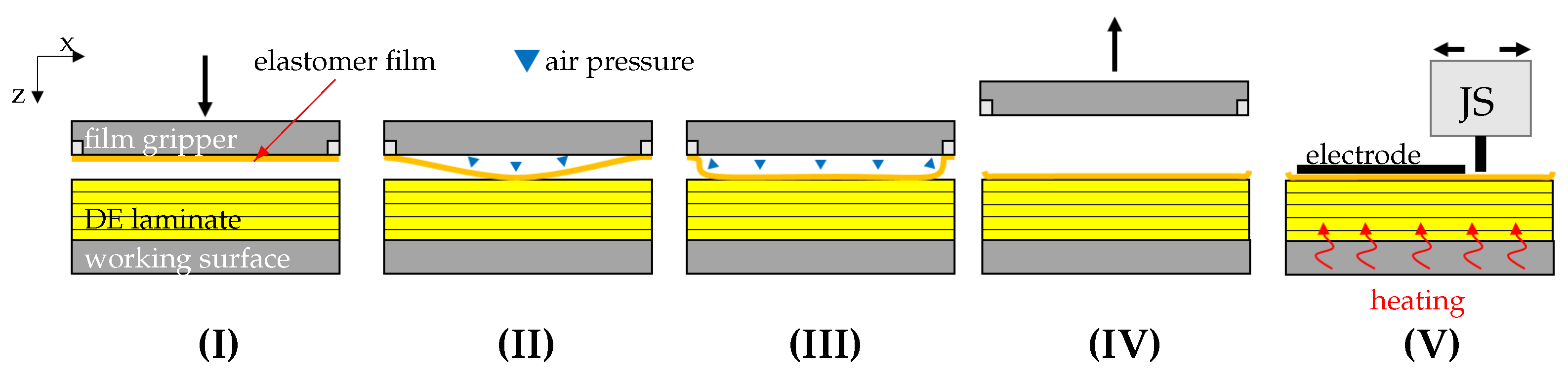
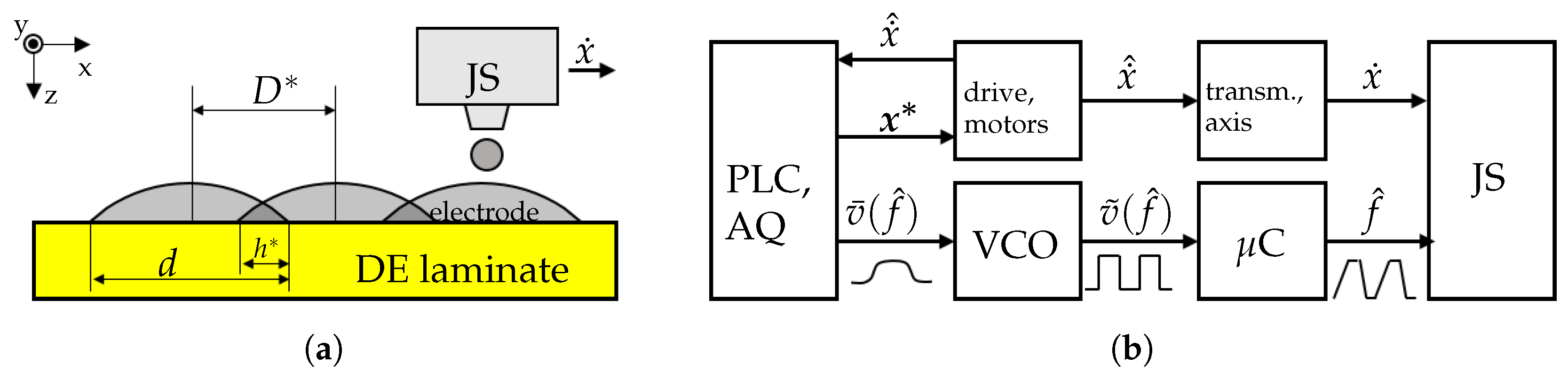
Figure 1 schematically illustrates the sheet-to-sheet manufacturing approach. After a rectangular elastomer sheet is fixed at the edges by a gripper and the film liner removed, it is positioned above the working surface, on which a prefabricated laminate can be located. By applying air pressure, the film is transferred from the gripper to the surface below, whereupon a pressure rise presses the film against the surface from the center to the borders to displace air. After that, the gripper releases the film edges and moves up. Subsequently, a jetting system (JS) prints an electrode pattern on the elastomer surface. To reduce solvent-induced swelling, the working surface heats the DE-laminate, so the solvent vaporizes after the electrode ink makes contact with the elastomer surface. To increase number of layers, steps (I) to (V) are successively repeated. In the following, the dielectric layer generation by vertical film placement is investigated theoretically and the integrated electrode application process is presented.
2.1. Modeling of Film Lamination
The film lamination is a crucial process step. On the one hand, wrinkles must be prevented to achieve even laminate layers and a planar overlap. For this reason, a minimum tensile elongation of the film can be beneficial to preclude compressive stress. On the other hand, undefined pre-stretch can also cause material warpage, which would be disadvantageous with respect to downstream manufacturing steps and final DE applications. Therefore, an analytical and numerical modeling approach is applied, to identify and quantize essential parameters and their influence on the residual strain after sheet-to-sheet film lamination.
To describe the presented lamination process and to evaluate residual material stretch λ
x, λ
y, a theory for thin, flexible and rectangular films under a uniformly, quasi-static applied constant load, needs to be applied. The problem of axisymmetric deformation of a transversely uniformly loaded and peripherally fixed circular membrane was examined by H. Hencky [
46] (the so called Föppl–Hencky membrane problem). The constitutive work deals with improving analytical membrane equations and solutions, e.g., in [
47]. Considering the presented lamination problem, gas pressurized membrane structures have already been objects of investigation in different fields of research. Bulging-tests of thin film specimens applying pressure
p is used for mechanical characterization purposes, in particular for determining Young’s modulus or Poisson’s ratio in combination with dedicated mathematical models to describe the membrane deflection [
48,
49]. Moreover, bringing inflated membranes into adhesive contact with rigid substrate surfaces is used to determine its adhesion energy γ [
50,
51]. For circular membranes, analytic closed form solutions for a static, frictionless contact between an inflated membrane and a rigid surface have been developed [
52,
53], as well as a phenomenological model describing dynamic membrane–plate contact with respect to vibration isolation devices [
54]. Srivastava et al. [
55] presented an analytical model describing the contact of largely deformed, long rectangular membranes with a rigid substrate, also assuming no-slip surface contact. Additionally, adhesive contact between film and substrate was taken into account in the second part of their work [
56]. The modeling approach mades use of an hyperelastic neo-Hookean material model, which satisfactorily described the used silicone elastosil material sufficiently for strains up to 30% [
57]. By way of comparison, the model appears applicable to the presented case.
Following Srivastava et al. [
55],
Figure 2a depicts the membrane geometry in the initial state (dashed line) and the assumed deformed state due to gravitational impact (solid line). The free deflection of the membrane’s center point, due to gravitational force, is denoted by
, the slope at the clamp
θm and due to symmetry about the
z-axis, the membrane’s width is denoted by
. The film’s thickness in the initial state is
h0. In the deformed state, the slope
varies from
at the center point to
θm at the clamps. In the free standing state, the coordinate
is mapped onto
. For a clamp angle
, the membrane’s coordinates can be described by
and
For a neo-Hookean material model, the equation
can be used to calculate the clamp angle
θm depending on the applied pressure
p. Evaluating Equation (
2), the maximum membrane deflection
δ for
and
is calculated by
The applied model in [
55] does not cover gravitational volume forces, which enabled simplification within the derivation of the equations. However, expecting only small membrane deflections, due to net weight, it was assumed that gravitational force acted normal to the (deformed) membrane surfaces and for the membrane thickness
h≈
h0. To evaluate the deflection due to gravitational volume force, an equivalent pressure load
was defined, where
g is the gravitational constant and
the membrane material’s mass density. Once the pressure
p rises, the membrane makes contact with the underlying laminate surface (see
Figure 2b). The resulting contact length is denoted by
c and the coordinate
is mapped onto the contact edge. The free standing membrane part (
) forms an arc with radius
R and can be described by:
describing stretch
under consideration of the contact distance
and the geometric quantities
R,
c,
a and
θm.
The dependency of applied pressure
p and stretch
is described by:
where
T denotes the membranes true in-plane tension and
is the small strain shear modulus, related to the small strain Young’s modulus
E. As a no-slip contact between membrane and surface was assumed, the residual stretch must increase from the center towards the contact edges once the membrane makes contact with the substrate and the pressure
p increases. As described in [
56], the stretch distribution in the contact zone can be calculated numerically as follows:
- 1.
In step
the quantities
are calculated for the initial contact, where
is a prescribed quantity (e.g.,
in case of gravitational induced initial deflection). Equations (
3)–(
10) are used to calculate all quantities for
.
- 2.
In the following step, the material coordinate is incremented by a prescribed value . An increment in contact length then is calculated by , so for the step it holds .
- 3.
All quantities for step are calculated again for the free standing membrane part. Steps 1 and 2 are repeated until c has reached a prescribed maximum value.
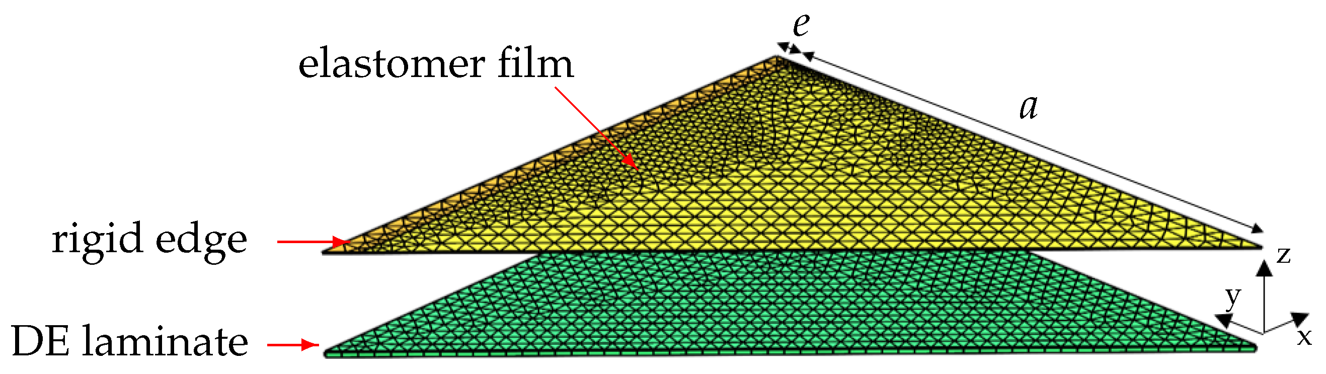
To validate the two-dimensional analytic model and to achieve a more detailed understanding of a real three-dimensional membrane, an FE-model (see
Figure 3) was implemented using COMSOL Multiphysics:
The FE-model represents an eighth part of the membrane, exploiting symmetry about yz-, xz- and the bisector plane. The elastomer film and DE laminate were modeled as neo-Hookean solid. In this investigation, the initial film thickness was exemplarily set to
μm. The membrane edges with
were rigidly fixed. A penalty contact with coupled adhesion was used to implement the no-slip condition between membrane and laminate surface. Gravitational volume force and additional pressure load were applied to the elastomer film. To improve convergence, the thin, compliant membrane was artificially stabilized by an additional spring foundation, increasing the effective membrane stiffness in the z-direction, while contact was calculated. Essential simulation parameters used in the study are summarized in
Table A1. The simulation contained the following steps:
- 1.
Calculating a pressure such that a prescribed deflection was reached in the first step.
- 2.
Moving the laminate in the z-direction towards the deflected membrane, so that the lowest membrane point coincided with the laminate surface. Applying a spring foundation to the membrane’s boundary in the deformed state to stabilize the solving contact problem.
- 3.
Increasing pressure p until desired contact length c was reached, e.g., .
- 4.
Deactivating artificial spring foundation.
2.2. Analytical and Simulation Results
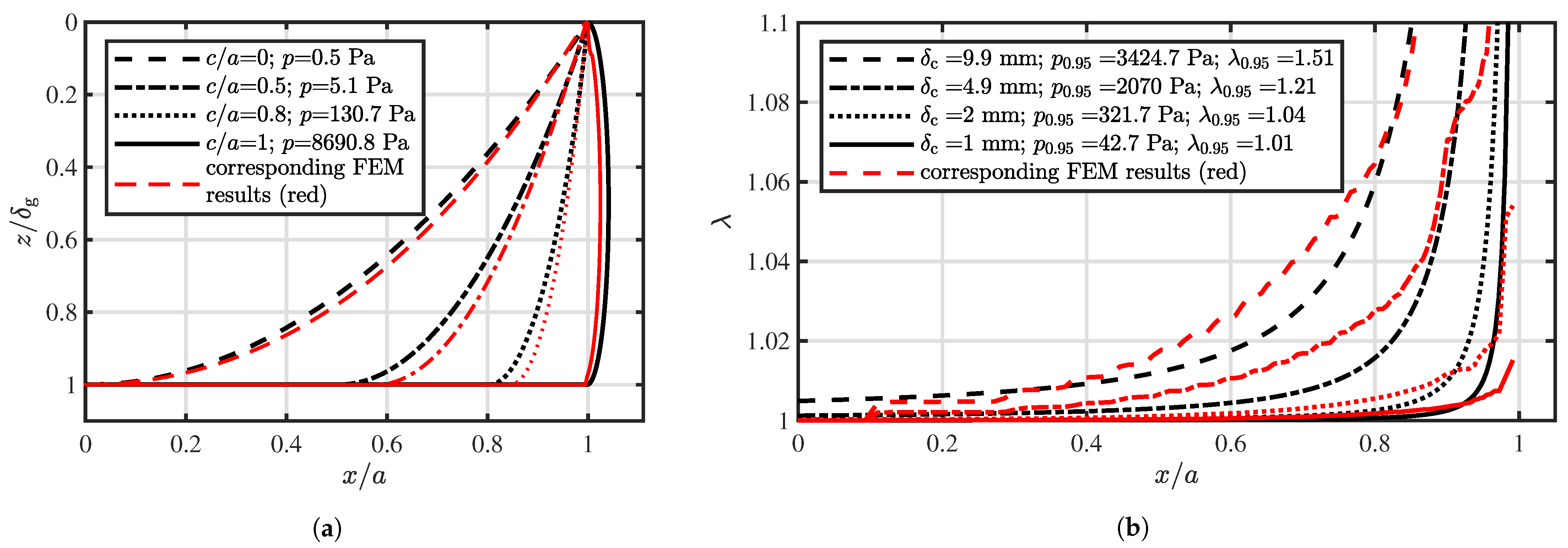
In
Figure 4a membrane profiles for an initial deflection
and various values of
were calculated and plotted using Equations (
1) and (
2). To increase contact length
c, the membrane pressure
p also had to be constantly increased up to a maximum pressure value
. Assuming the full contact surface
, a compressive force
would result, which needed to be absorbed by the working surface below. The FEM results basically coincided well with the analytic approach, although the calculated displacement and the resulting membrane shapes slightly differed. A different number of finite elements and the differing stress state (1D and 3D) regarding both approaches might explain these discrepancies.
A maximum contact overlap of
would cause disproportionately high values for
and
p. Therefore, a consideration would be inexpedient. Hence, a maximum contact overlap of
was defined as a reference for calculating values, marked by an index “0.95”.
decreased in order to reduce
.
Figure 4b depicts the resulting membrane stretch
considering different initial values for
. Due to the no-slip condition, the resulting stretch
increased from the center towards the boundary, as mentioned before. The initial deflection
, particularly the relation
, had a significant impact both on
and
p. Reducing
from
to 1
yielded a reduction in maximum residual stretch from
to
. Additionally, the relating pressure reduced from
to
. Assuming a predetermined membrane width
, the contact distance
must be small and should be even smaller than the gravity caused initial deflection, in order to minimize remaining stretch
and pressure
p. Moreover, it can also be stated that using large membranes also led to small pre-stretch values
, because, for a defined
, the ratio
was minimized. Corresponding FE-simulation results illustrate a comparable stretch distribution. However, the numerically calculated stretch appeared systematically higher, which could be traced back to the three dimensional state of strain.
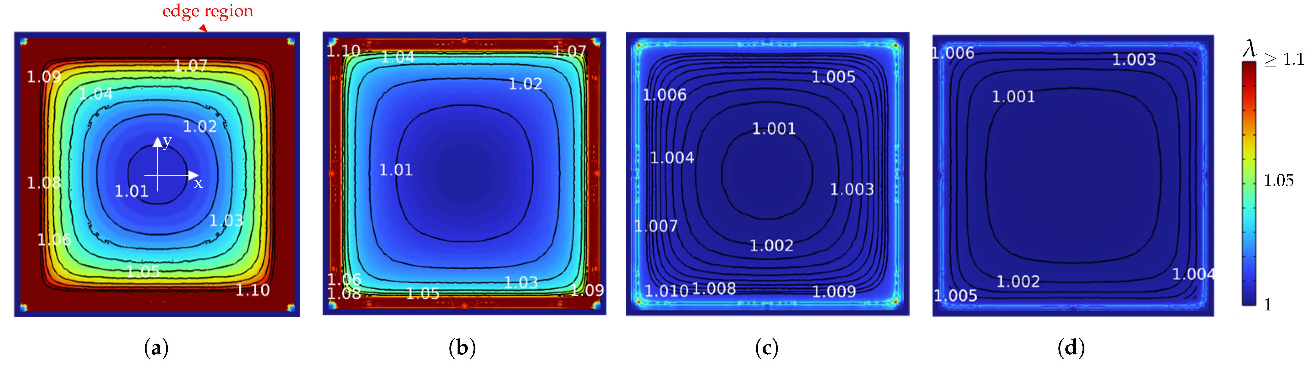
In
Figure 5 the equivalent stretch in the x- and y-directions of the free membrane’s surface after a 95% no-slip contact is illustrated for different values of
. Iso-contour lines mark equivalent stretch regions. Due to the rigid boundary condition, no deformation occurred at the
wide membrane edges. The plots illustrate non-homogeneous stretch distributions, which started with circular iso-contours in the center and segued into rectangular ones at the edges. In the corners pre-stretch slightly rose compared to values along the
x- or
y-axes. As already assumed, the total pre-stretch decreased significantly by decreasing
(
Figure 5a) down to
(
Figure 5d). Moreover,
Figure 5c illustrates that almost the entire surface stretch was below 1%. Close to the clamp edges a sharp increase could be observed, which was explained by the bending stretch of the 5% inflated free standing membrane part. However, after sheet lamination with
, pre-stretch below 1% could be expected for more than 90% of the dielectric surface area (excluding the fixated edges).
2.3. Electrode Application Process
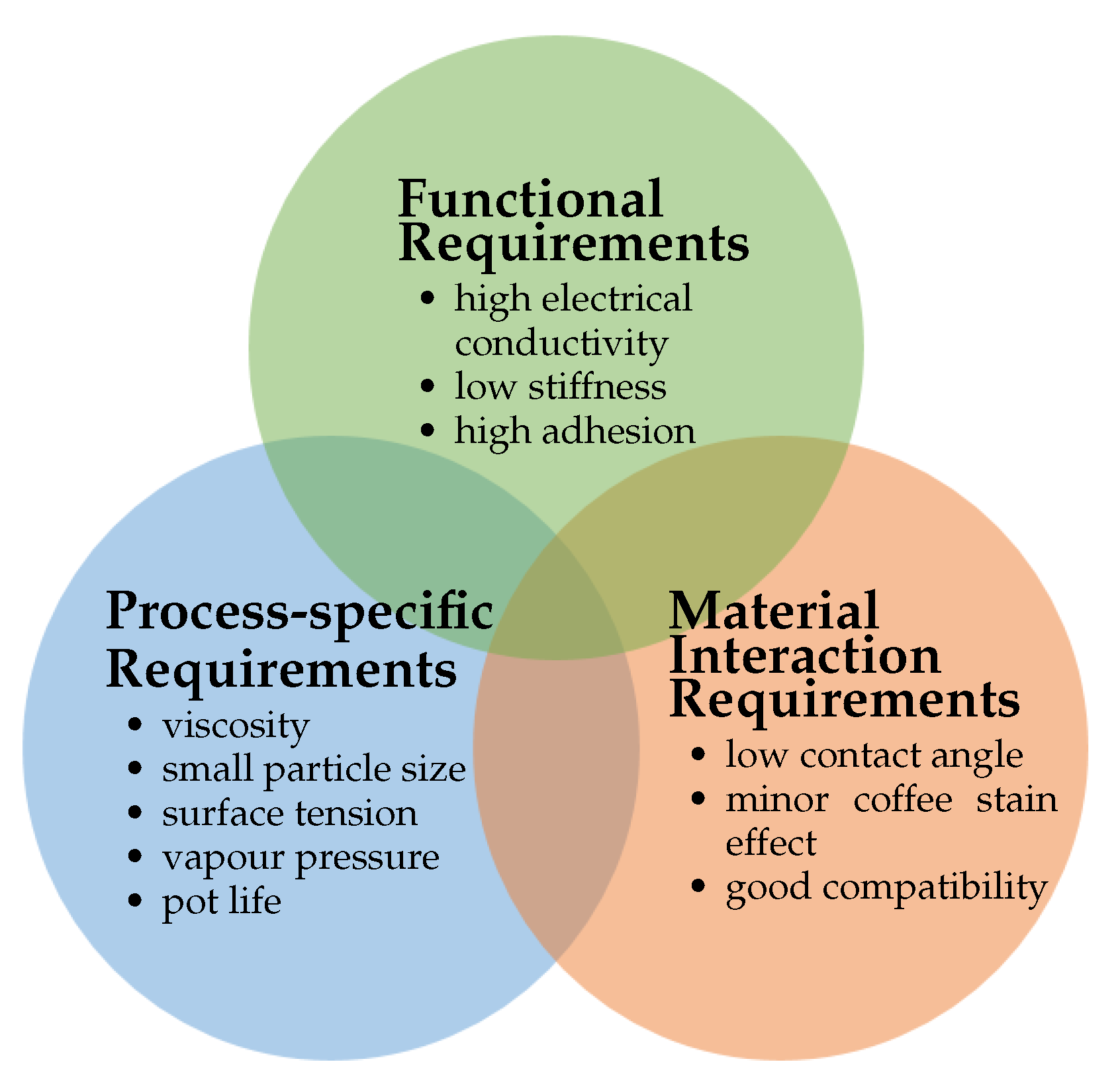
In contrast to standardized elastomer materials for DE transducers, such as film and fluid, there is currently no commercially achievable material for the electrode. A standard material is necessary to choose the most suitable electrode application technology. One of the important functional requirements of the electrode layer is good electrical conductivity. A higher electrical conductivity leads to lower energy loss, especially in the case of dynamic applications, and reduces the response time. Another important functional requirement is low mechanical stiffness. In order to avoid a stiffening of the DE transducer, the electrode layer should be compliant and as thin as possible. Moreover, the adhesional function of the electrode layer is required to avoid delamination of multi-layer DE transducers under tensile force. Additional to the functional requirements of the electrode layer, according to [
25], there are two more aspects to consider for the material development: process requirements and ink–elastomer film interaction, as depicted in
Figure 6. The process requirements are specifically derived from the application technology. In this paper, only contactless printing technologies were considered because they readily enable geometrical versatility and do not lead to contact-caused damage or strains on the surface of the applied layer. Whereas functional requirements address the electrode layer, process requirements refer to the electrode ink. The requirements for the printing process are the fluid properties, viscosity, particle diameter surface tension, vapor pressure, and pot life. In order to optimize the process quality, the fluid properties of the electrode ink should be adjusted precisely regarding the printer type. Additionally, the interaction between the printed electrode drop and the elastomer film has a significant role in forming the electrode layer. Contact angle affects the thickness of the printed drop and, together with coffee stain, the surface roughness of the layer. According to [
25], these requirements should be considered when developing the electrode material and in the application process.
Commercial carbon black-filled liquid silicone materials Elastosil
® LR 3162, POWERSIL
® 402 and POWERSIL
® 420 were investigated and evaluated in [
31,
35] in terms of the mentioned criteria. Modified carbon-based silicone (conductive rubber) electrodes fulfil the requirements and are frequently used to fabricate electrode layers. The electrode material used in the manufacturing consists of an elastomer matrix blended with Carbon Black particles Elastosil
® LR 3162 (EL 3162). The Carbon Black particles establish electrical conductivity; simultaneously, the elastomer matrix provides adhesion and mechanical stability between dielectric layers. Conductive rubbers are highlighted due to their high stretchability. They can also keep their electrical conductivity at high stretch ratios, and long cycles [
58]. However, EL 3162 is not printable as it is available. It has a very high viscosity and is diluted with a non-polar solvent, which entirely evaporates after printing. The solvent solves the conductive rubber and provides a stable suspension. In addition, the wetting behavior is enhanced using the solvent.
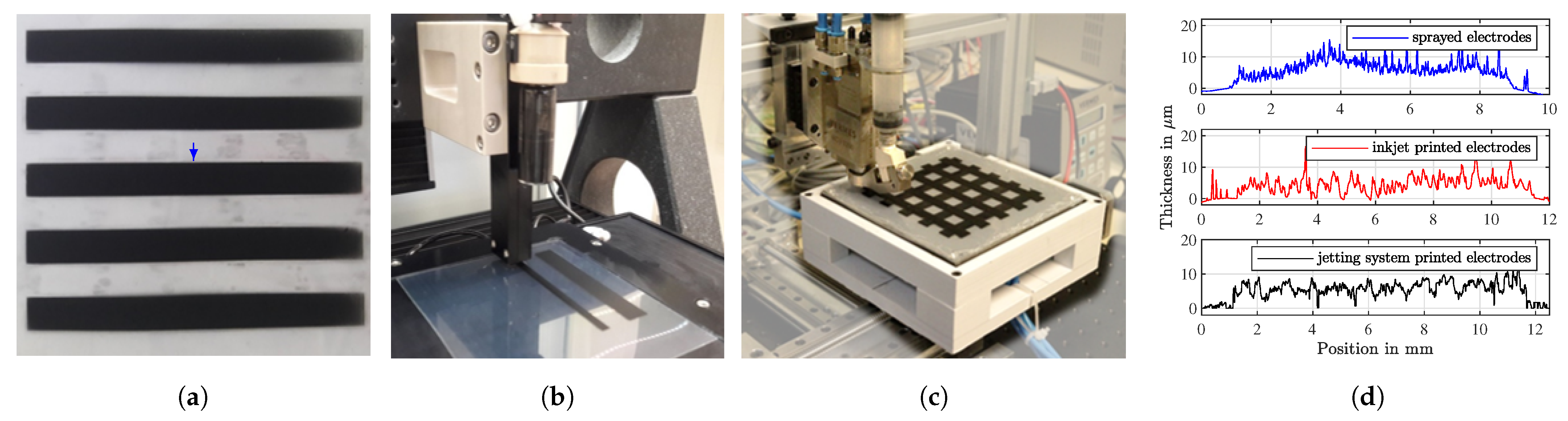
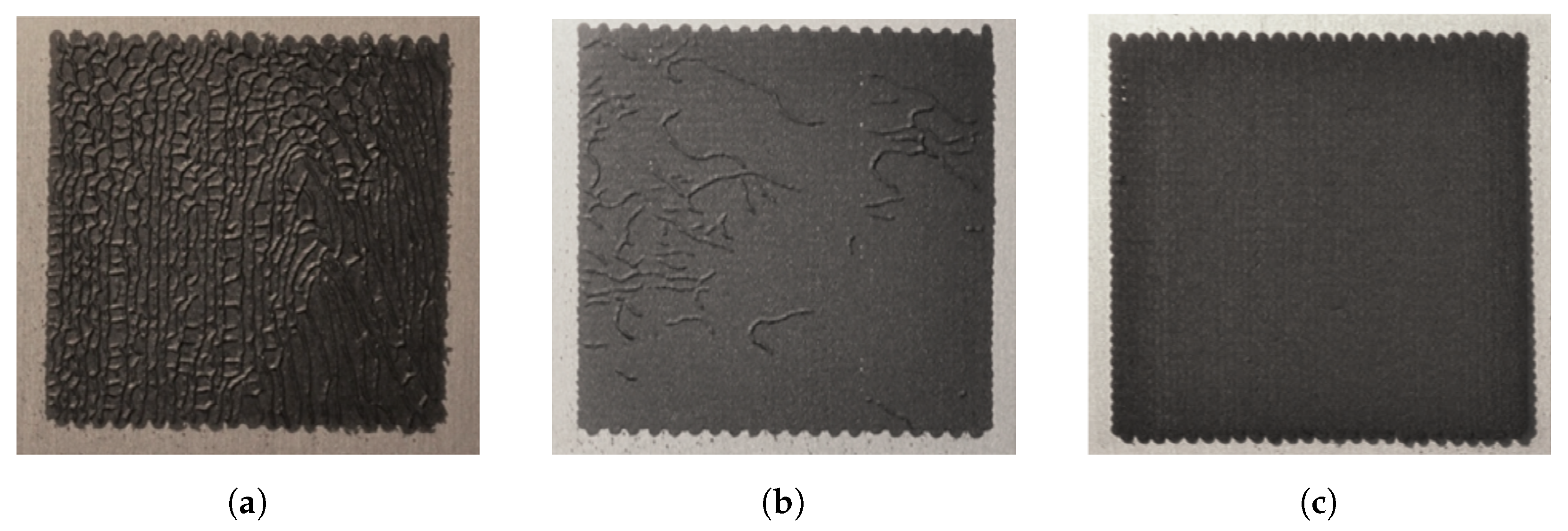
As electrode application methods, spray coating and two printing technologies were experimentally compared using the electrode material EL 3162, and the results are discussed. Spray coating through a shadow mask is a simple method in terms of electrode ink preparation. Electrode inks can be sprayed in a wide range of fluid properties, e.g., viscosity and particle size. However, the method consumes electrode ink very ineffectively and needs more process quality and precision.
Figure 7a shows sprayed layers with the spray head Multispray Mod. 940 (Düsen-Schlick GmbH, Untersiemau, Germany). Due to the low resolution of the spraying position, inhomogeneous surface profiles were measured, as depicted in
Figure 7d. Moreover, inaccuracies could occur on the counter sharpness because of the spray pressure. Thus, the layers in the middle were wider and thicker than at the edges.
Figure 7b shows the printing test with the inkjet print head AD-K-801 (microdrop Technologies GmbH, Norderstedt, Germany). The printed layers had a very homogeneous surface profile and price counters, see
Figure 7d. However, inkjet printers require very low viscosity and particle size stability, which strictly limits development of a conductive ink [
31,
59]. The low viscosity of the ink for inkjet printers causes a coffee stain, which is visible at the high roughness of the measured profile in
Figure 7d. Accordingly, inkjet nozzles are frequently clogged, so inkjet printing is considered not robust enough as an electrode application process for DE laminate manufacturing. A further printing method is the jetting system MDS 3280 (Vermes Microdispensing GmbH, Holzkirchen, Germany ), depicted in
Figure 7c. The surface profile measurement of an electrode layer printed via the jetting system is depicted in
Figure 7d. It is currently utilized to print electrode layers in a thickness between 5 μm and 10 μm with better homogeneity and reproducibility than those of inkjet printers. The surface properties, e.g., thickness, can be improved by adjusting the viscosity, in contrast to inkjet printers, as they are robust regarding ink requirements [
35]. Inks with a large range of viscosity and particle size can be printed. Moreover, its modular construction enables configuring elements of the jetting mechanism, e.g., nozzle and tappet, and changing them without further support. The robustness and modularity are significantly advantageous for the manufacturing process. Therefore, the jetting system MDS 3280 was chosen as the electrode application technology and integrated into the manufacturing process. It is an additive manufacturing method for several precise jetting and dosing applications.
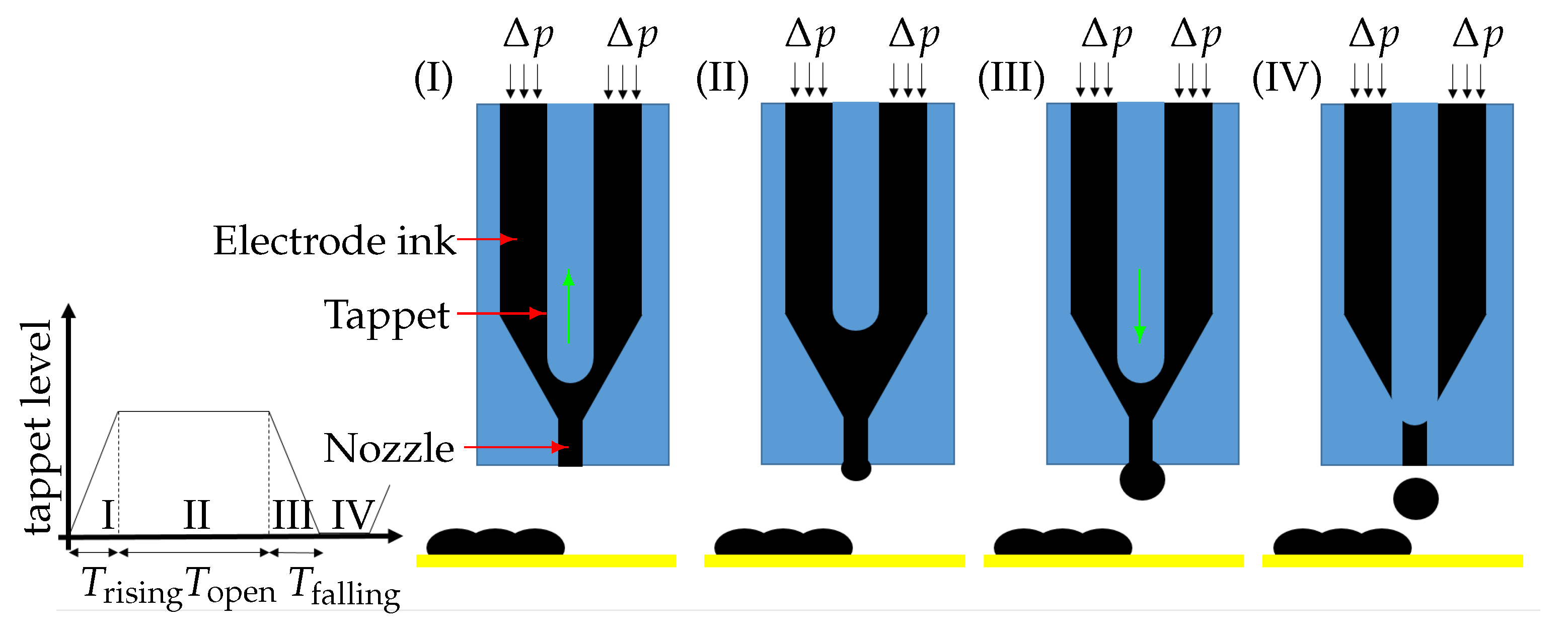
The working principle and construction are briefly introduced according to
Figure 8. The ink cartridge is connected to the conical chamber, where a tappet is positioned on the nozzle orifice. A piezo actuator drives the tappet via a lever and, thus, the nozzle is closed and opened. The ink in the cartridge, under air pressure
p, fills the conical chamber to which the nozzle is mounted. By the reciprocating movement of the tappet, the ink is jetted out through the nozzle orifice. The tappet motion is controlled by adjusting the time intervals with the controller:
,
,
, and the tappet level h. In addition, the cartridge pressure is adjustable up to 8 bar.
The jetting process has four states, regarding the tappets’ reciprocating motion:
- I.
Upward movement: the applied voltage is changed, and the tappet is lifted.
- II.
Opened state: the applied voltage is constant during time , and the tappet stays lifted. The ink in the chamber under air pressure flows through the nozzle orifice.
- III.
Downward movement: the applied voltage is changed, and the tappet moves downwards. In this state, the ink is jetted by the pressure of the downwards-moving tappet in addition to the air pressure. The tappet level and result in the tappet velocity and, thus, pressure is generated.
- IV.
Closed state: the applied voltage on the piezo actuator is constant, and the tappet closes the nozzle orifice.
The adjustable printing parameters , , , cartridge pressure, and tappet level, enable the droplet volume to be precisely adjusted.
Another important aspect is the swelling effect by the non-polar solvent. The elastomer film absorbs solvent contained in the printed ink, and it causes temporary swelling of the elastomer film. Therefore, a heating system was integrated into the lamination plate to avoid the swelling effect. Thus, as depicted in
Figure 9, the solvent immediately evaporated once the droplet landed on the heated elastomer film surface [
60]. It is important to avoid premature curing on the heated plate. Curing EL 3162 at 165 °C is the post-treatment step after completing the lamination process. The curing process, however, is accelerated at increased temperature. Therefore, a heated lamination plate should lead to quick vaporization of the solvent without accelerating the curing.
3. Realization of Manufacturing Process on Laboratory Scale
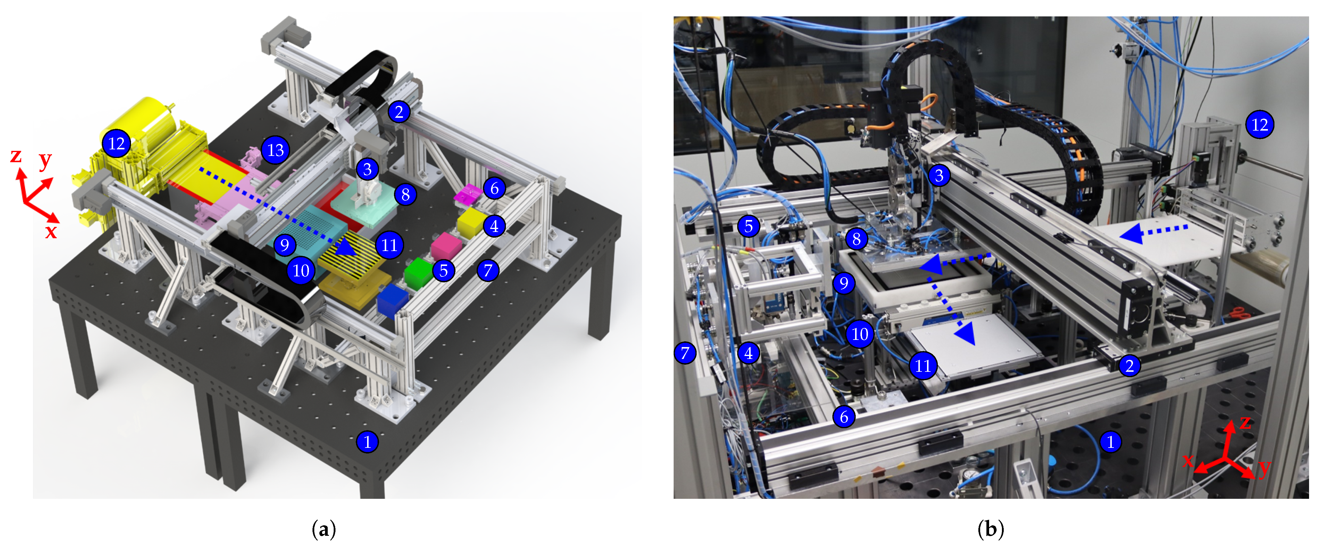
Design and realization of the laboratory scale process are depicted in
Figure 10a,b. It was located in an air-conditioned area meeting ISO cleanroom class 7. The experimental arrangement was installed on a mounting plate (1) with a total surface area of
. Positioning and motion control tasks were enabled by a spindle axis gantry system (2) with traverse speed up to 300
providing a static repeat accuracy of
μm in each direction. The axes were driven by synchronous drives supporting real-time communication with a Siemens S7-1500 technology programmable logic controller (PLC). The z-axis contained three quick-change pallet systems (3) for flexible tool mounting, both frontal and from below, with a repeating accuracy
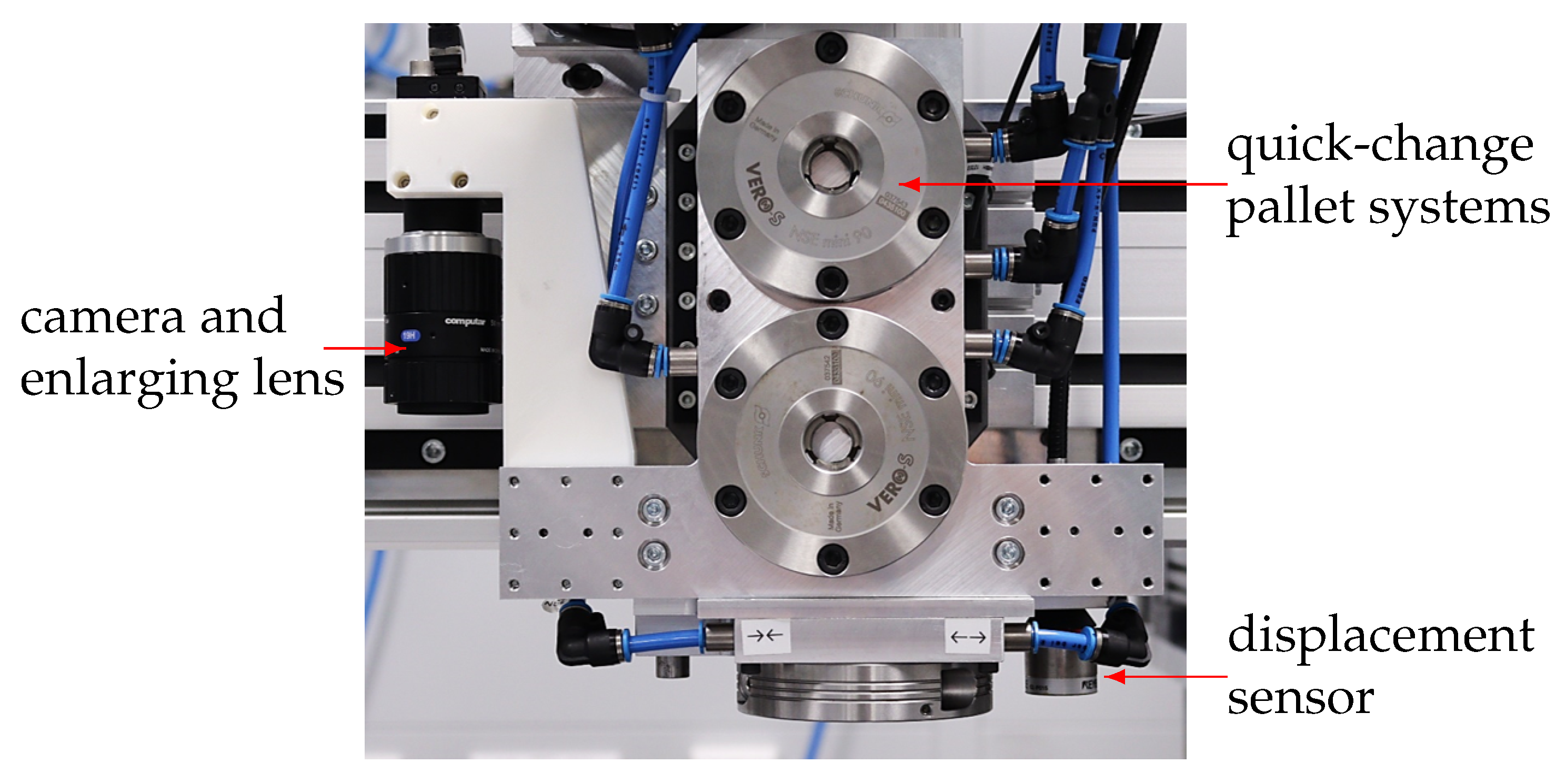
μm. Tools, e.g., electrode application system (4), laser head (5) and rolling knife (6), were located in the module retainer (7) in the front part. They could be automatically attached to the z-axis. The gripper module (8), which mainly enabled the film handling, was attached to the gantry. The base below (9) provided a storage area for the gripper module and contributed to the liner separation. An ionization module (10) was provided to neutralize electric charge after liner separation. On the working surface (11) film lamination, electrode application and cutting took place, to achieve high positioning accuracy of the production steps.
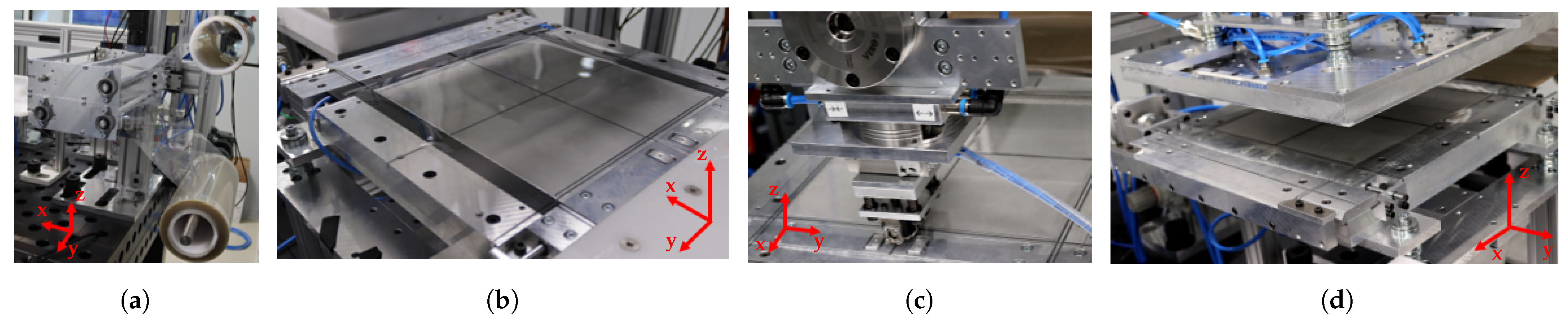
The film supply (12) is presented in
Figure 11a in more detail. Two elastomer film rolls could be provided in the film supply and separately fed into the process by adjusting the film outlet in the z-direction. Driven shafts facilitated tightening and pulling back the film material. First, the film was pushed on a vacuum surface (13), see
Figure 11b. The 90° rotatable circular blade was attached to the
z-axis’ bottom (
Figure 11c) and used to cut a
sized sheet. As depicted in
Figure 11d, subsequently, the gripper module (8) sucked the sheet from above bringing it to the gripper base (9), where the liner separation took place.
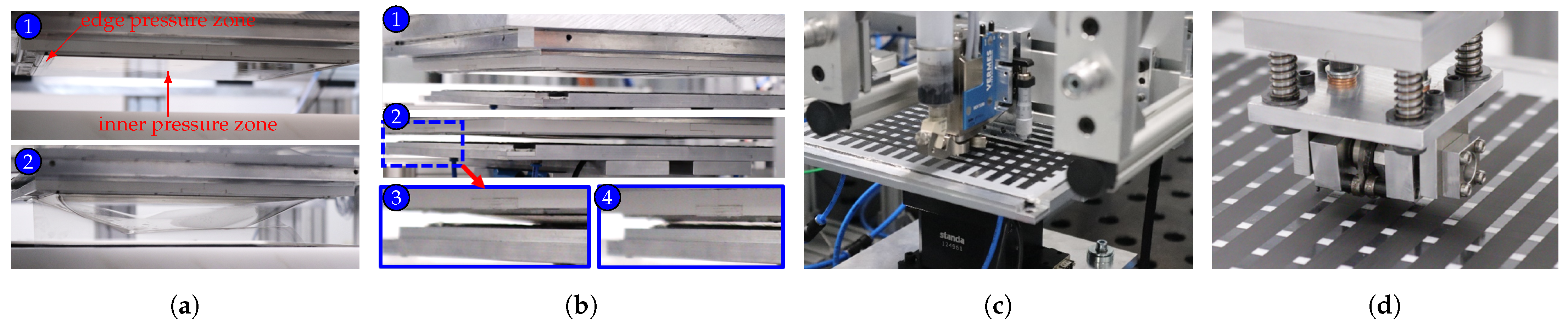
The gripper module, shown in
Figure 12a, consisted of two independently adjustable pressure areas: a
large inner porous aluminum surface and a closed, about 5
wide, edge region. The sucking edge fixed the elastomer film’s surrounding borders and simultaneously sealed the inner pressure zone against the environment. Applying an inner pressure separated the elastomer film from its liner. After reducing electrostatic charge with an ionizer, the film lamination, in accordance with
Section 2.2, took place. The gripper was positioned above the heated working surface, see
Figure 12b (1) and a contact distance
was adjusted (2). During steps (2) to (4), the elastomer film was inflated and made contact with the DE laminate. To release the film, an overpressure was applied to the edges while the gripper moved up again. After replacing the gripper by the printing system, an electrode pattern was printed onto the substrate. Beforehand, corresponding electrode patterns had to be translated into machine code. The working surfaces were heated up to a temperature of about 85
, as preliminary investigations indicated that temperature induced evaporation of the applied solvent-based electrode ink and reduced swelling effects [
60]. The current temperature was controlled by the PLC using a PT1000 sensor. Once the electrode application was finished, the described steps were repeated until a desired number of DE layers had been reached. In a final step, the circular blade could be used for cutting linear slits to obtain separated DE entities, as depicted in
Figure 12d. For in situ process monitoring, the
z-axis contained a Hikrobot MV-CS200-10GC 20 MP camera with changeable enlarger lens, as shown in
Figure 13. Moreover, a confocal chromatic displacement sensor Keyence CL-P015G, with a distance resolution of 3
, was provided to measure electrode surfaces and thickness of the transparent DE layers.
Adaptive Drop Frequency Control
For manufacturing electrode layers, the before-mentioned jetting system (JS), Vermes MDS 3280, was chosen. However, to achieve homogeneous electrode layers, the drop frequency had to be precisely adapted to the variable axis speed
. The drop based electrode application process is schematically depicted in
Figure 14a. By adjusting the JS parameters, the drop diameter
d could be defined. Moreover, an overlap
could be specified to avoid gaps between the single drops on the substrate. Using these quantities, the set point drop distance
was determined. As a function of the absolute print head speed
, the corresponding trigger frequency was given by
With respect to the realized process on a laboratory scale, the implemented drop frequency control is schematically illustrated in
Figure 14b. For axis movement, a set point
was transmitted to the drives, which generated an axis speed
and returned a measurand
, calculated from the motor speed and kinematic dependencies of the spindle axis. Based on
, a drop frequency
was estimated using Equation (
11) and an analog voltage
was used as input signal for a voltage controlled oscillator (VCO). The VCO analogously modulated the frequency of a square wave signal
forwarding it to the jetting system’s controller (
μC). By edge detection, the JS was triggered and drops were released, as described in
Section 2.3. Due to delay times and transmission behavior of the mechanical transmission and axis, the current JS speed
could differ from the measurand
, which would result in deviations of
. Moreover, in accordance with
Section 2, the additional delay time of the jetting system
had to be considered, too. Hence, a pre-control transfer function
was implemented to compensate for delay times.
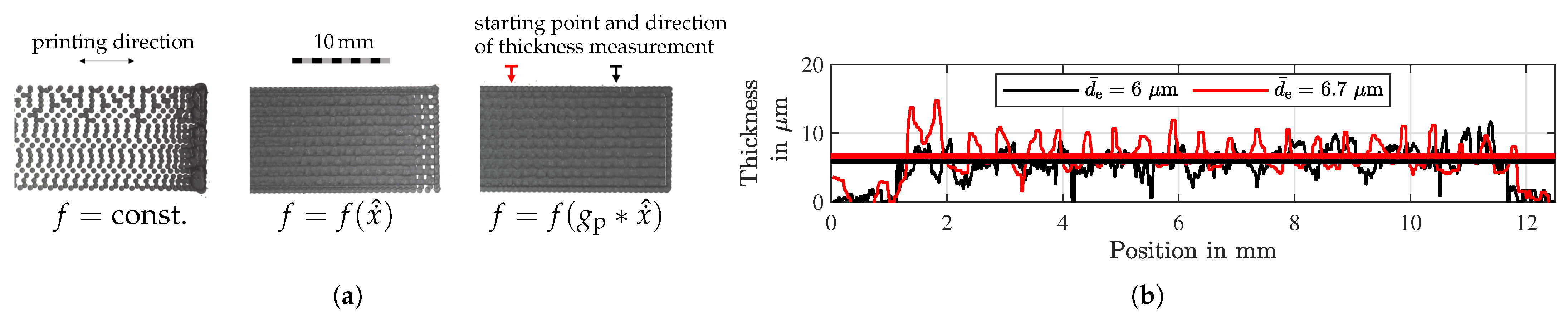
In
Figure 15a printing results for different drop frequency controls are illustrated. When printing with constant drop frequency
, the electrode could accumulate when axis speed reduced. In this case, the drop frequency was additionally halved to measure the drop diameter of
and to illustrate the negative effect of missing frequency adjustment. Simply using
significantly improved the electrode uniformity, whereas the pre-control with dead time compensation
also provided a uniform electrode surface at the edge regions for high acceleration values. Using a confocal chromatic displacement sensor, two electrode elevation profiles perpendicular to the printing direction yielded average electrode thicknesses of 6 μm and 6.7 μm with standard deviations of 1.5 μm and 2.1 μm respectively. The deviations indicated a surface roughness resulting e.g., from the coffee stain effect.
4. Testing Manufactured DE Transducers
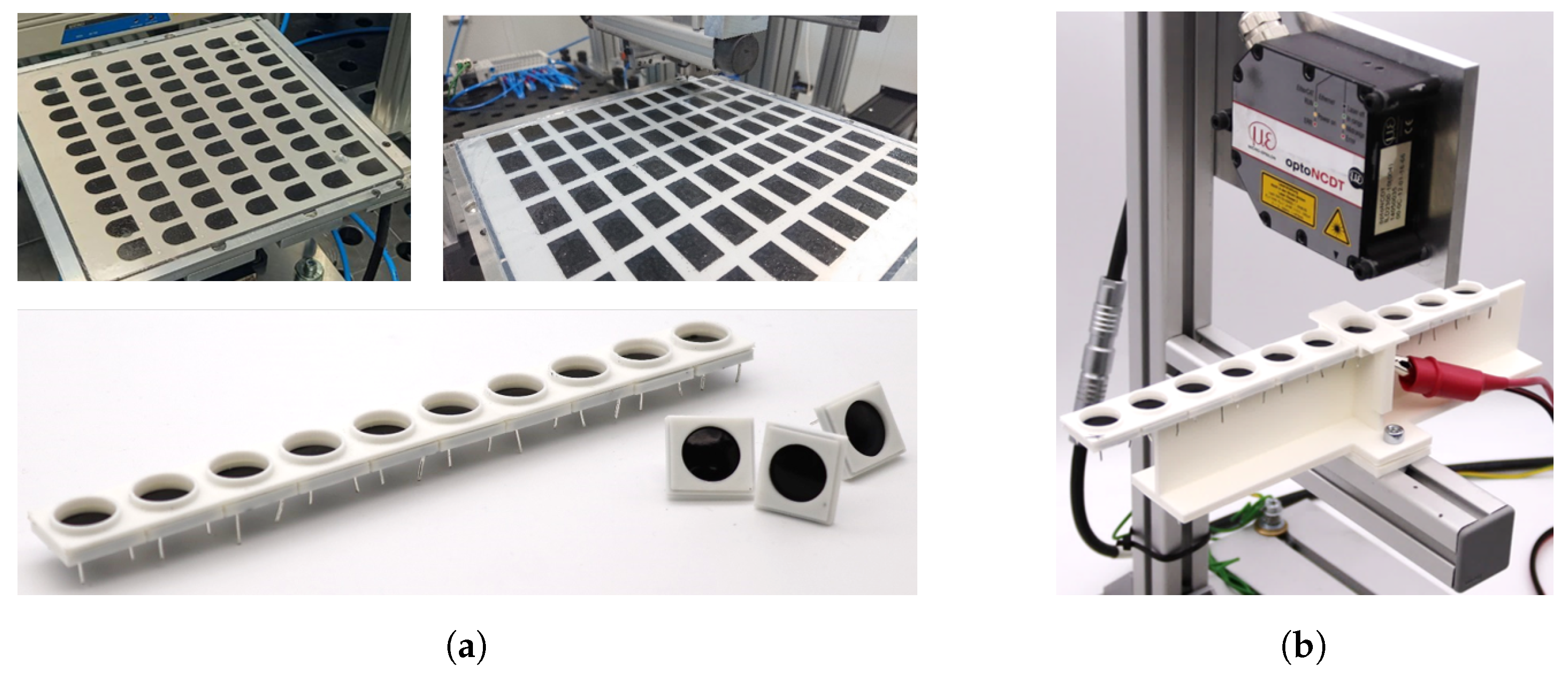
In order to evaluate the quality of the developed manufacturing process, two types of DE transducers were produced and experimentally characterized. As depicted in
Figure 16a, DE laminates were manufactured and processed into circular buckling dielectric elastomer transducers, according to the work of M. Gareis et al. [
18]. They consisted of
Elastosil
® 2030 layers with a film thickness of
and
layers of circular electrode shapes with radius
. Additionally, rectangular electrode areas for lateral electrical contacting were provided. The elements were cut out and arranged in a frame, holding ten actuators and providing electrical contact wires. The test rig in
Figure 16b comprised a frame holder and a MicroEpsilon optoNCDT laser triangulation sensor to measure the buckling transducer’s center point deflection. A trapezoidal voltage ramp with a rise, hold and fall time of 5
was applied to the specimens. The voltage was measured using a TESTEC TT-SI 9010 high voltage differential probe. In addition to actuation performance, the electrical series resistance and capacity values at the electrical contacts were measured using a BK Precision 880 LCR Meter. Using the respective electrode geometry’s dimensions, an expected initial capacity value
was analytically calculated by:
where the initial active electrode surface is denoted by
, the initial dielectric thickness by
h0 and the number of capacities by
. A relative permittivity of
was assumed [
43].
In
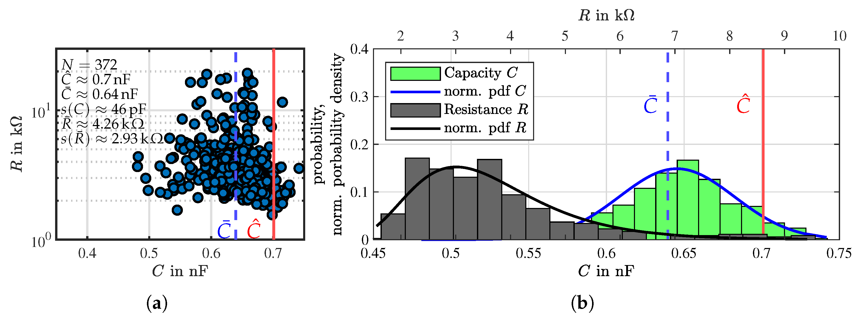
Figure 17a capacity and ohmic resistance measurement results are illustrated as a scatter-plot. The mean value of the capacitance
was about 8.6% lower than the calculated capacity value
using Equation (
12). Moreover, capacity values scattered significantly, quantized by standard deviation
. It can also be stated that some capacity values were higher than the analytical mean value, which might be explained by manufacturing tolerances and, in particular, by larger electrode surfaces or parasitic influences on the capacity measurement. In contrast, resistance values were distributed over a range of more than one decade. Probably, the electric contact resistance had a significant impact. It might also be possible that a varying electrode thickness, with locally distributed low conductivity spots, could have influenced the results. Thus, a comparison to analytic results was considered unsuitable. In
Figure 17b the histograms and the fitted, normalized probability density functions (pdf) suggest that mainly random errors influenced the manufactured DE transducers. This might indicate that the electrode surface area slightly varied or that remaining air inclusions were present, which could reduce the DE transducer’s capacitance.
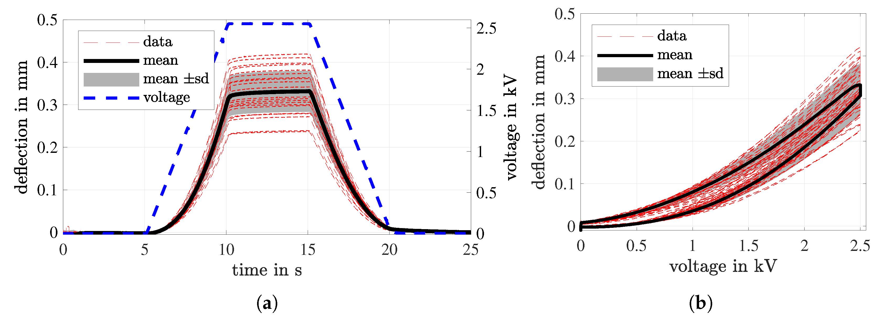
In
Figure 18a the measured displacement versus time for
specimens is illustrated. The maximum deflection
during the hold time varied from
and a maximum standard deviation
μm was evaluated. The deflection characteristic during rise and fall time was in accordance with a squared dependence of actuation voltage
v. During hold time, a small creep of less than
could be observed for most specimens. Among other reasons, this could be traced back to creep and relaxation processes inside the electrode material [
61], insufficient layer bonding or a compliant mechanical membrane mounting. The relatively high standard deviation might indicate active layers with insufficient electrical bonding, performance reduction due to variation in electrode thickness [
26] or also inaccuracies with respect to the mechanical frame mounting. Beforehand, preliminary investigations of the impact of uncertainties on the actuation of DE multilayer transducers showed that deviations in actuation stretch and force could be more pronounced regarding DE transducers with a small number of DE layers [
62]. In
Figure 18b the mean course of deflection versus applied voltage pointed out slight hysteresis behavior, which might have been caused by material creep [
61].
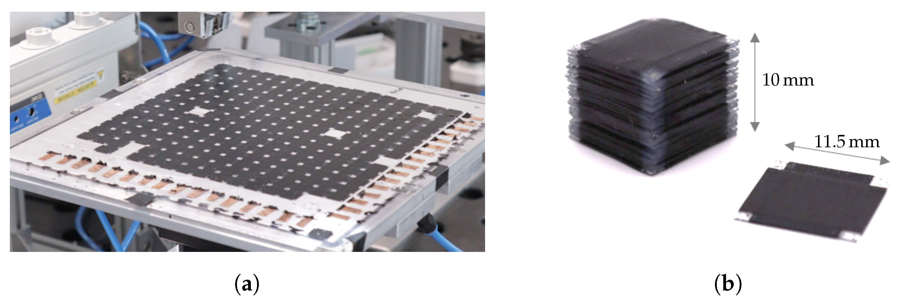
Moreover, 20 μm thin elastomer films were processed into DE laminates for manufacturing submodules for DE stack transducers. They consisted of
Elastosil
® 2030 layers and
layers of crosswise printed electrode stripes with a width of
. Thus, a maximum number of 256 DE submodules was obtained from one laminate. For short-time testing of the dielectric strength, the laminate’s edge region was cut off and small copper stripes and pasty electrode material was used for electrically connecting the electrodes line by line, as shown in
Figure 19a. A voltage step of
was applied to each column, whereby the corresponding row was connected to ground. The voltage was held at least 3
. By visual inspection and monitoring voltage drop, deficient locations were identified. After testing, the DE laminate was cut and 45 deficient of 256 total submodules were rejected, as depicted in
Figure 19a. The first two rows revealed a significantly high defect density, suggesting a systematic process fault. As exemplarily shown in
Figure 19b, functional submodules could be further processed into DE stack transducers [
44].
5. Conclusions and Outlook
This work presents a dry layer manufacturing approach for dielectric elastomer transducers on a large scale. The vertical film lamination of pre-fabricated elastomer film sheets offers various advantages in contrast to other manufacturing methods. Manufacturing time is reduced, as no curing time is needed for the dielectric. High quality dielectric layers with homogeneous and reproducible properties can be provided, as both appropriate materials are commercially available and upstream inspection methods can be applied to the film material. The electrode application process, via jetting the system, proved robust and fast and enabled the manufacturing of electrode coatings with thicknesses in the micrometer range. Using the jetting system MDS 3280 is suitable both for printing large electrode surfaces and also for more complex electrode patterns, considering a precise jetting frequency adjustment. Thus, customized DETs can easily be manufactured.
The process was successfully realized on a laboratory scale. With respect to the process design, care was taken to ensure easy and fast process modifications and upgrades. The integrated measuring systems enable in situ process monitoring for direct process optimizations. Various DETs were manufactured and tests were exemplarily performed on buckling transducers and on a DE laminate for making DE stack transducers. As preliminary considerations confirmed, pre-stretch of DETs could be minimized using a small initial contact distance before transferring the film onto the DE laminate. A large number of working DETs validated the process quality. However, variation in electrical and mechanical behavior of specimens was determined, which indicated remaining optimization potential, both of the manufacturing process and subsequent processing steps.
For future work, further optimizations of the manufacturing process are intended to improve DETs’ reproducibility and to minimize scrap rate. Among other aspects, possible air inclusions between the layers must be fully eliminated, as performance could be significantly influenced. Besides solvent vaporization, the effect of laminate heating needs to be examined more closely to evaluate mechanical interaction between laminate and working surface and to evaluate possible, temperature-induced deformations. Long time measurements of DET specimens are needed to determine lifetime and possible weak points and to define further process improvement measures.


