
Research on Self-Recovery Control Algorithm of Quadruped Robot Fall Based on Reinforcement Learning


Abstract
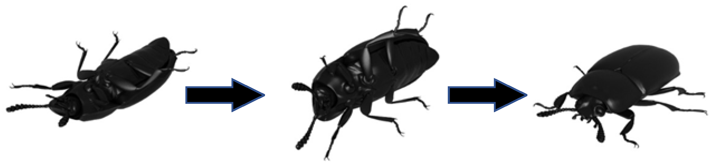
1. Introduction
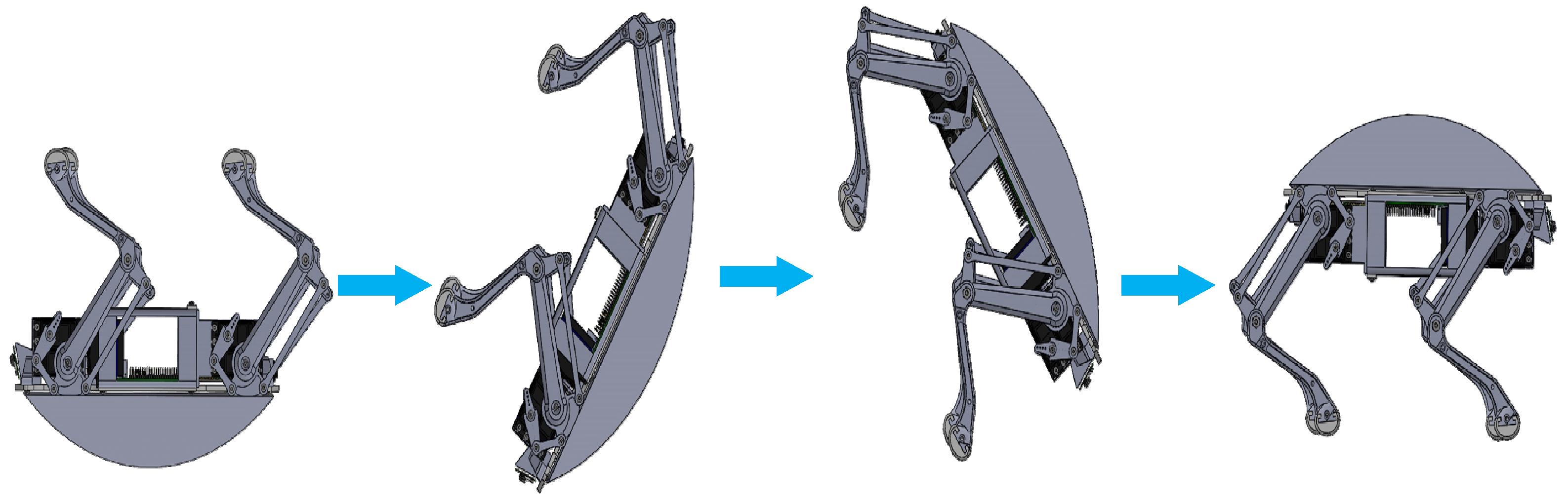
2. Self-Recovery Motion Model of Quadruped Robot Fall
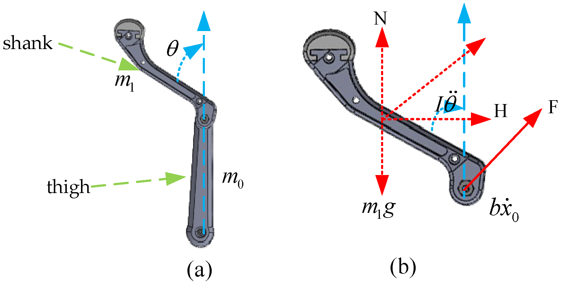
2.1. The Kinematic Model of Single-Leg Swing
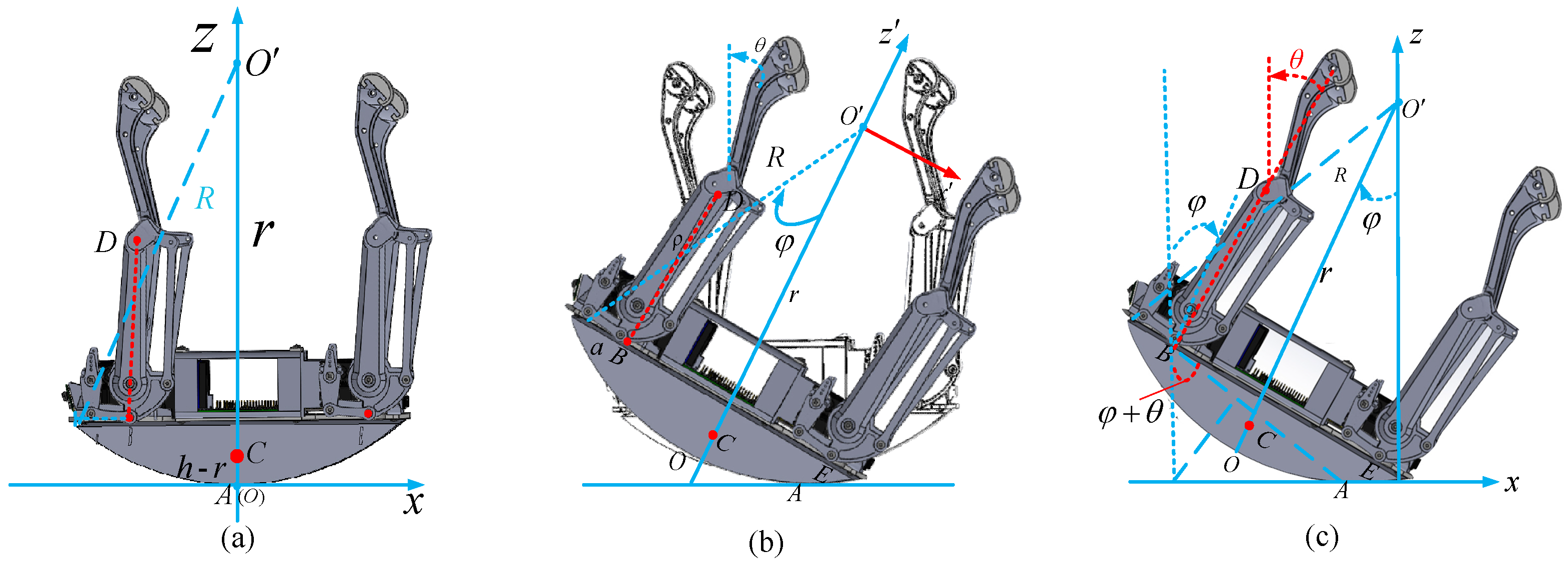
2.2. Self-Recovery Motion Model of Quadruped Robot after Falling
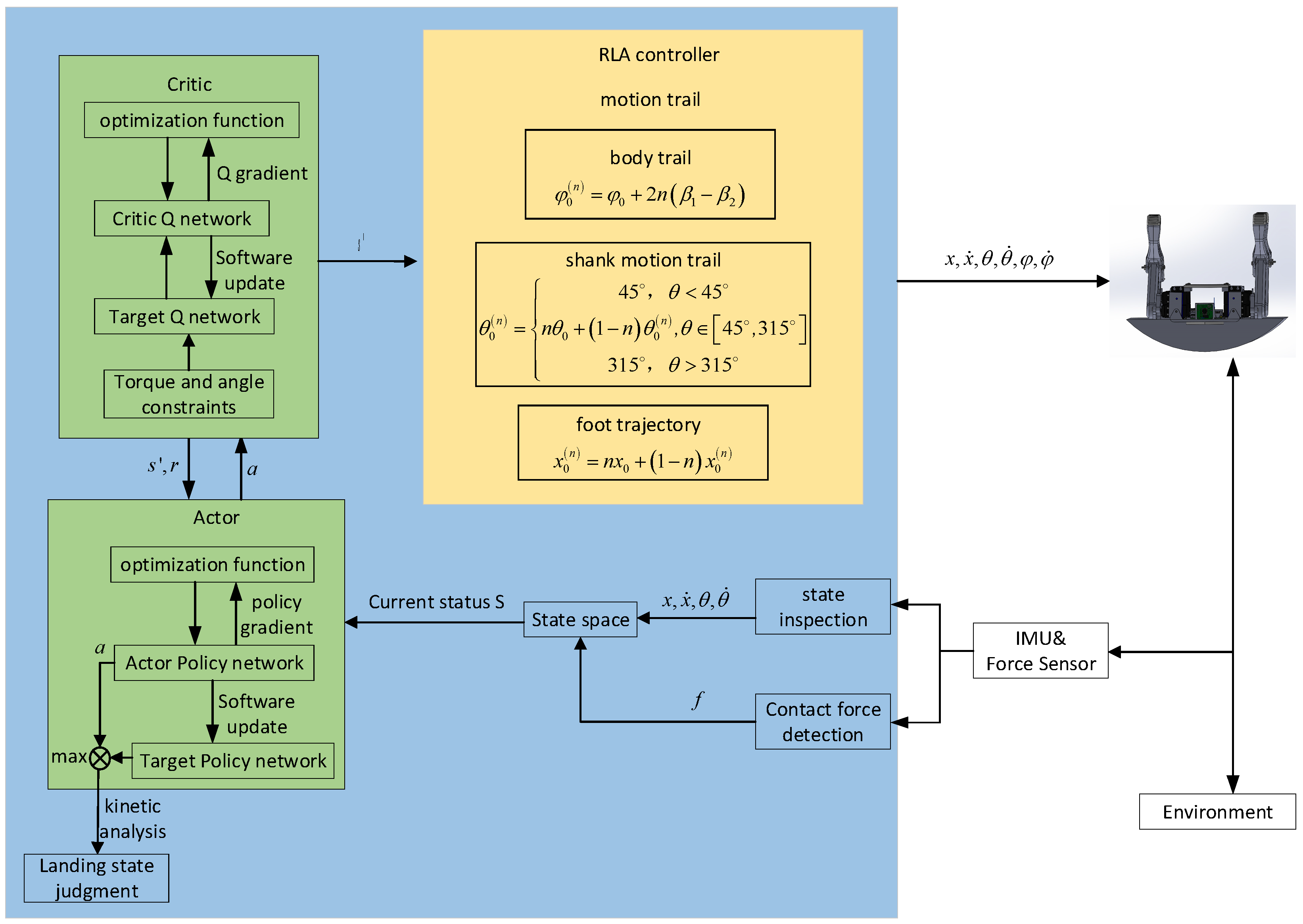
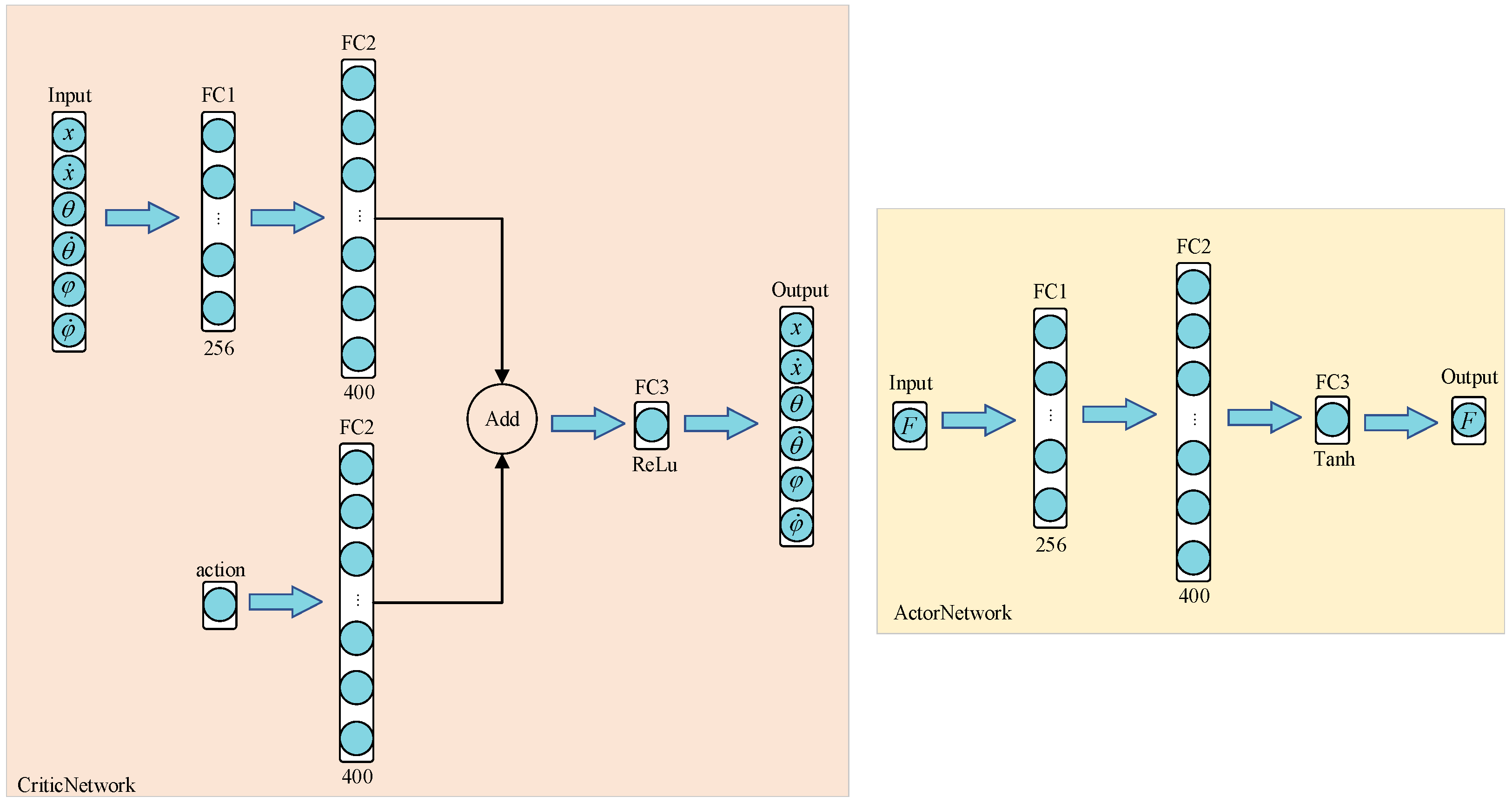
3. Control Strategy
| Algorithm 1 The DDPG Control Algorithm | |
| Input: state space and action space ; | |
| Output: action; | |
| 1: | Initial agent and environment; |
| 2: | while doTraining = true do |
| 3: | if then |
| 4: | Set episode ; |
| 5: | Select action according to the current observed state ; |
| 6: | Observe reward and observe new state after executing action ; |
| 7: | Store transition in |
| 8: | Perform the action ; |
| 9: | Store data and update state ; |
| 10: | Identify and update the target neural network; |
| 11: | Identify and train evaluation neural network; |
| 12: | else |
| 13: | End the training; |
| 14: | end if |
| 15: | end while |
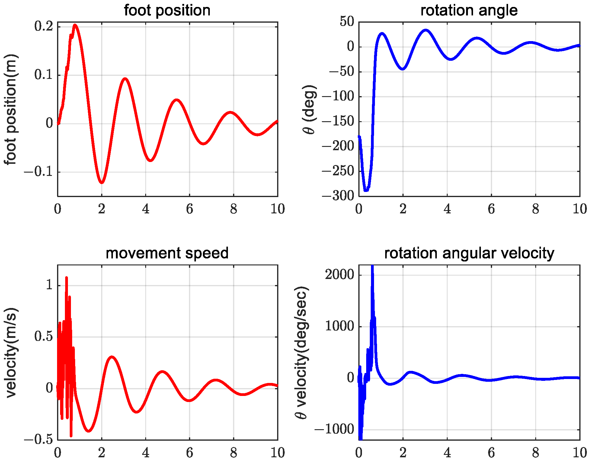
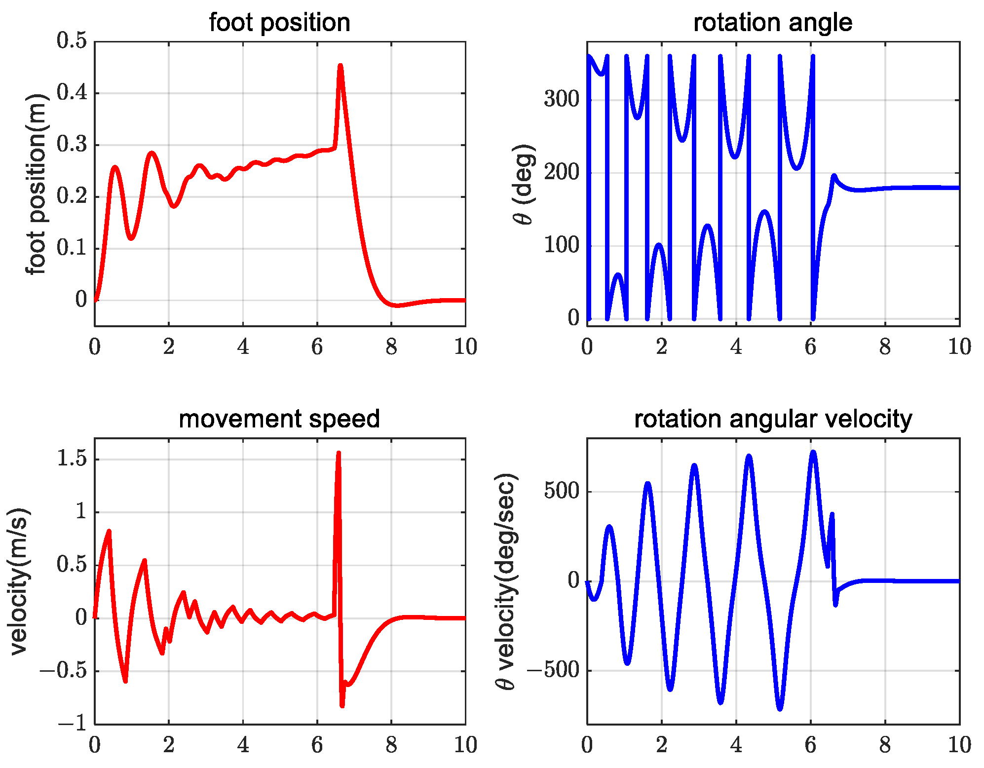
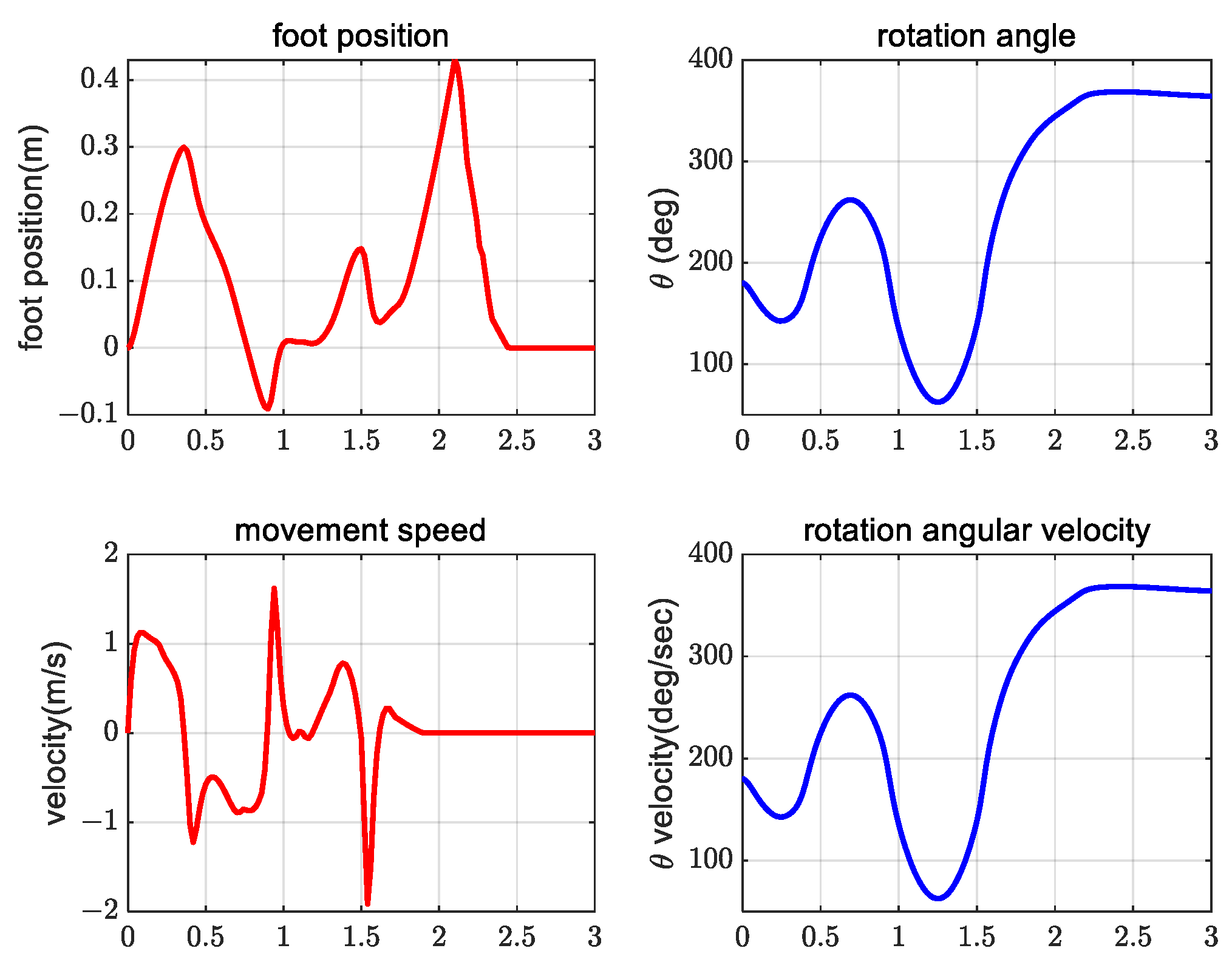
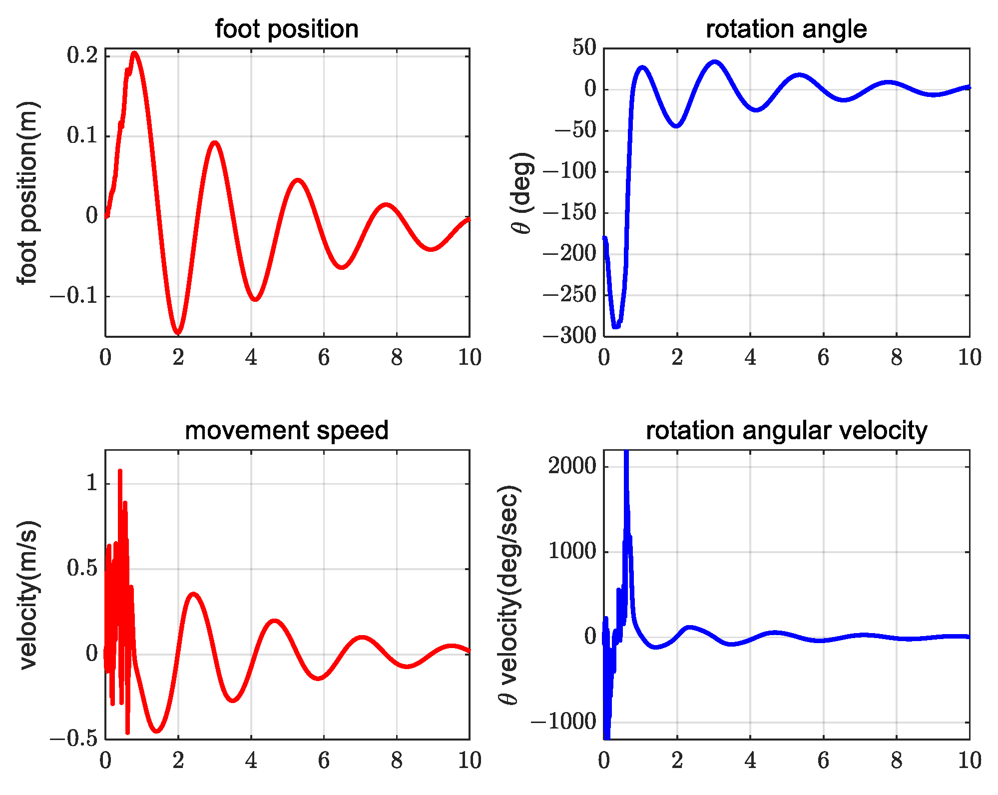
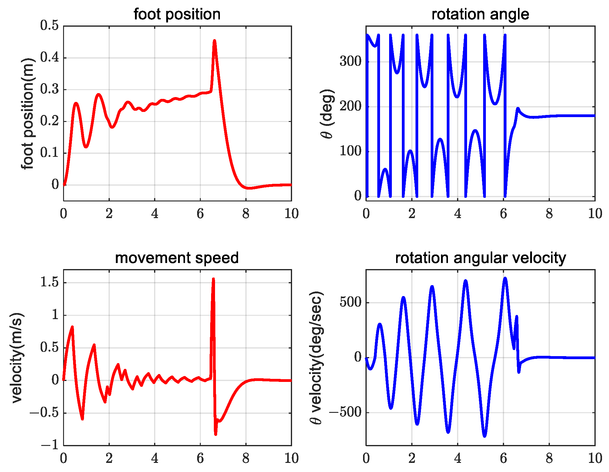
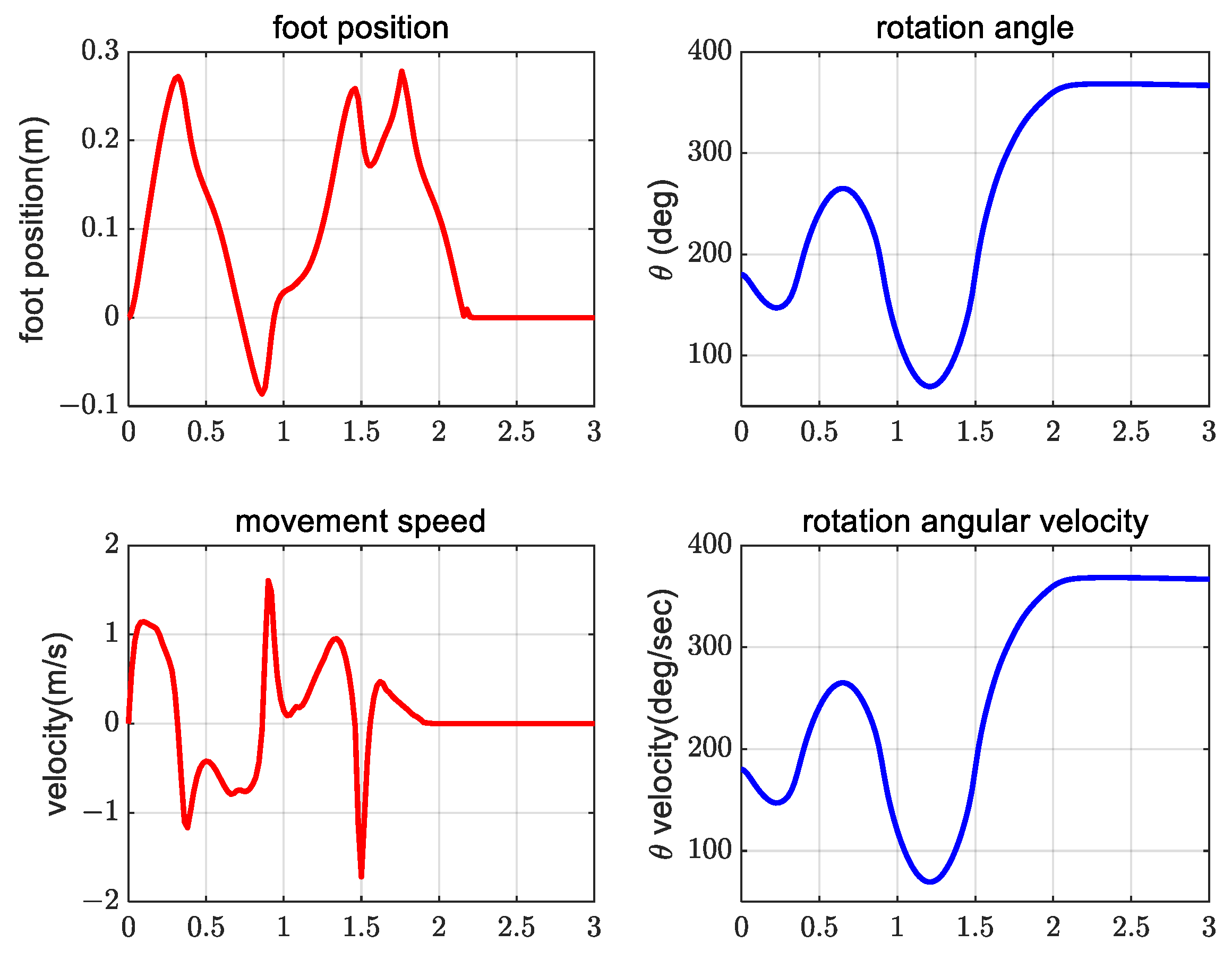
4. Simulation Verification Experiment
5. Conclusions and Future Work
5.1. Conclusions
5.2. Future Work
Author Contributions
Funding
Data Availability Statement
Conflicts of Interest
References
- Wang, T.-M.; Tao, Y.; Liu, H. Current Researches and Future Development Trend of Intelligent Robot: A Review. Int. J. Autom. Comput. 2018, 15, 525–546. [Google Scholar] [CrossRef]
- Biswal, P.; Mohanty, P.K. Development of quadruped walking robots: A review. Ain Shams Eng. J. 2020, 12, 2017–2031. [Google Scholar] [CrossRef]
- Iniewski, K. Radiation Effects in Semiconductors; CRC Press: Boca Raton, FL, USA, 2018. [Google Scholar] [CrossRef]
- Tokur, D.; Grimmer, M.; Seyfarth, A. Review of balance recovery in response to external perturbations during daily activities. Hum. Mov. Sci. 2019, 69, 102546. [Google Scholar] [CrossRef]
- Inaba, M.; Kanehiro, F.; Kagami, S.; Inoue, H. Two-armed bipedal robot that can walk, roll over and stand up. In Proceedings of the 1995 IEEE/RSJ International Conference on Intelligent Robots and Systems, Human Robot Interaction and Cooperative Robots, Pittsburgh, PA, USA, 5–9 August 1995; Volume 3, pp. 297–302. [Google Scholar] [CrossRef]
- Kuroki, Y. A small biped entertainment robot. In Proceedings of the MHS2001. 2001 International Symposium on Micromechatronics and Human Science (Cat. No. 01TH8583), Nagoya, Japan, 9–12 September 2001; pp. 3–4. [Google Scholar] [CrossRef]
- Kuroki, Y.; Fujita, M.; Ishida, T.; Nagasaka, K.; Yamaguchi, J. A small biped entertainment robot exploring attractive applications. In Proceedings of the 2003 IEEE International Conference on Robotics and Automation (Cat. No. 03CH37422), Taipei, Taiwan, 14–19 September 2003; Volume 1, pp. 471–476. [Google Scholar] [CrossRef]
- Ha, I.; Tamura, Y.; Asama, H. Development of open platform humanoid robot DARwIn-OP. Adv. Robot. 2013, 27, 223–232. [Google Scholar] [CrossRef]
- Mordatch, I.; Todorov, E.; Popović, Z. Discovery of complex behaviors through contact-invariant optimization. ACM Trans. Graph. 2012, 31, 1–8. [Google Scholar] [CrossRef]
- Semini, C.; Goldsmith, J.; Rehman, B.U.; Frigerio, M.; Barasuol, V.; Focchi, M.; Caldwell, D.G. Design overview of the hydraulic quadruped robots. In Proceedings of the Fourteenth Scandinavian International Conference on Fluid Power, Tampere, Finland, 20–22 May 2015; pp. 20–22. [Google Scholar]
- Stückler, J.; Schwenk, J.; Behnke, S. Getting Back on Two Feet: Reliable Standing-up Routines for a Humanoid Robot. In IAS; IOS Press: Amsterdam, The Netherlands, 2003; pp. 676–685. [Google Scholar]
- Saranli, U.; Rizzi, A.A.; Koditschek, D.E. Model-Based Dynamic Self-Righting Maneuvers for a Hexapedal Robot. Int. J. Robot. Res. 2004, 23, 903–918. [Google Scholar] [CrossRef]
- Kakiuchi, Y.; Kamon, M.; Shimomura, N.; Yukizaki, S.; Takasugi, N.; Nozawa, S.; Okada, K.; Inaba, M. Development of life-sized humanoid robot platform with robustness for falling down, long time working and error occurrence. In Proceedings of the 2017 IEEE/RSJ International Conference on Intelligent Robots and Systems (IROS), Vancouver, BC, Canada, 24–28 September 2017; pp. 689–696. [Google Scholar] [CrossRef]
- Khorram, M.; Moosavian, S.A.A. Balance recovery of a quadruped robot. In Proceedings of the 2015 3rd RSI International Conference on Robotics and Mechatronics (ICROM), Tehran, Iran, 7–9 October 2015; pp. 259–264. [Google Scholar] [CrossRef]
- Lee, J.; Hwangbo, J.; Hutter, M. Robust recovery controller for a quadrupedal robot using deep reinforcement learning. arXiv 2019, arXiv:1901.07517. [Google Scholar] [CrossRef]
- Sutton, R.S.; Barto, A.G. Reinforcement Learning: An Introduction; The MIT Press: Cambridge, MA, USA, 2017. [Google Scholar]
- Xie, Z.; Clary, P.; Dao, J.; Morais, P.; Hurst, J.; Panne, M. Learning locomotion skills for cassie: Iterative design and sim-to-real. In Proceedings of the Conference on Robot Learning, Virtual, 16–18 November 2020; pp. 317–329. [Google Scholar]
- Sheng, J.; Chen, Y.; Fang, X.; Zhang, W.; Song, R.; Zheng, Y.; Li, Y. Bio-Inspired Rhythmic Locomotion for Quadruped Robots. IEEE Robot. Autom. Lett. 2022, 7, 6782–6789. [Google Scholar] [CrossRef]
- Shen, W.-M.; Krivokon, M.; Chiu, H.; Everist, J.; Rubenstein, M.; Venkatesh, J. Multimode locomotion via SuperBot reconfigurable robots. Auton. Robot. 2006, 20, 165–177. [Google Scholar] [CrossRef]
- Tan, N.; Mohan, R.E.; Elangovan, K. Scorpio: A biomimetic reconfigurable rolling–crawling robot. Int. J. Adv. Robot. Syst. 2016, 13, 1729881416658180. [Google Scholar] [CrossRef]
- Nguyen, K.-N.; Kojio, Y.; Noda, S.; Sugai, F.; Kojima, K.; Kakiuchi, Y.; Okada, K.; Inaba, M. Dynamic Fall Recovery Motion Generation on Biped Robot with Shell Protector. IEEE Robot. Autom. Lett. 2021, 6, 6741–6748. [Google Scholar] [CrossRef]
- Bar-On, Y.M.; Phillips, R.; Milo, R. The biomass distribution on Earth. Proc. Natl. Acad. Sci. USA 2018, 115, 6506–6511. [Google Scholar] [CrossRef] [PubMed]
- Hwangbo, J.; Lee, J.; Dosovitskiy, A.; Bellicoso, D.; Tsounis, V.; Koltun, V.; Hutter, M. Learning agile and dynamic motor skills for legged robots. Sci. Robot. 2019, 4, eaau5872. [Google Scholar] [CrossRef] [PubMed]
- Susanto, E.; Wibowo, A.S.; Rachman, E.G. Fuzzy Swing Up Control and Optimal State Feedback Stabilization for Self-Erecting Inverted Pendulum. IEEE Access 2020, 8, 6496–6504. [Google Scholar] [CrossRef]
- Waszak, M.; Langowski, R. An Automatic Self-Tuning Control System Design for an Inverted Pendulum. IEEE Access 2020, 8, 26726–26738. [Google Scholar] [CrossRef]
- Yu, Y.; Yi, F.; An, K.; Chang, C. Simulation study of linear two-stage inverted pendulum based on SimMechanics. Sci. Technol. Eng. 2020, 20, 8239–8244. [Google Scholar]
- Dao, P.N.; Liu, Y.-C. Adaptive Reinforcement Learning Strategy with Sliding Mode Control for Unknown and Disturbed Wheeled Inverted Pendulum. Int. J. Control Autom. Syst. 2020, 19, 1139–1150. [Google Scholar] [CrossRef]
- Yu, J.; Zhang, X. The Global Control of First Order Rotary Parallel Double Inverted Pendulum System. In Proceedings of the 2021 40th Chinese Control Conference (CCC), Shanghai, China, 26–28 July 2021; pp. 2773–2778. [Google Scholar] [CrossRef]
- Gao, H.; Li, X.; Gao, C.; Wu, J. Neural Network Supervision Control Strategy for Inverted Pendulum Tracking Control. Discret. Dyn. Nat. Soc. 2021, 2021, 1–14. [Google Scholar] [CrossRef]
- Peng, S.; Ding, X.; Yang, F.; Xu, K. Motion planning and implementation for the self-recovery of an overturned multi-legged robot. Robotica 2015, 35, 1107–1120. [Google Scholar] [CrossRef]
- Ma, Z.; Ma, Q.; Lyu, R.; Wang, J. Running Analysis of Quadruped Robot with Flexible Spine. J. Northeast. Univ. Nat. Sci. 2020, 41, 113–118. [Google Scholar] [CrossRef]
- Lillicrap, T.P.; Hunt, J.J.; Pritzel, A.; Heess, N.; Erez, T.; Tassa, Y.; Silver, D.; Wierstra, D. Continuous control with deep reinforcement learning. arXiv 2015, arXiv:1509.02971. [Google Scholar] [CrossRef]
- Özalp, R.; Varol, N.K.; Taşci, B.; Uçar, A. A Review of Deep Reinforcement Learning Algorithms and Comparative Results on Inverted Pendulum System. Mach. Learn. Paradig. 2020, 18, 237–256. [Google Scholar] [CrossRef]
- Manoonpong, P.; Parlitz, U.; Wörgötter, F. Neural control and adaptive neural forward models for insect-like, energy-efficient, and adaptable locomotion of walking machines. Front. Neural Circuits 2013, 7, 12. [Google Scholar] [CrossRef] [PubMed]
- Wu, W.; Gao, L. Posture self-stabilizer of a biped robot based on training platform and reinforcement learning. Robot. Auton. Syst. 2017, 98, 42–55. [Google Scholar] [CrossRef]
- Mohamed, M.; Anayi, F.; Packianather, M.; Samad, B.A.; Yahya, K. Simulating LQR and PID controllers to stabilise a three-link robotic system. In Proceedings of the 2nd International Conference on Advance Computing and Innovative Technologies in Engineering (ICACITE), Greater Noida, India, 28–29 April 2022; pp. 2033–2036. [Google Scholar] [CrossRef]
- Bakarac, P.; Klauco, M.; Fikar, M. Comparison of inverted pendulum stabilization with PID, LQ, and MPC control. In Proceedings of the 2018 Cybernetics & Informatics (K&I), Lazy pod Makytou, Slovakia, 31 January–3 February 2018; pp. 1–6. [Google Scholar] [CrossRef]
- Ratnayake, D.T.; Parnichkun, M. LQR-Based Stabilization and Position Control of a Mobile Double Inverted Pendulum. IOP Conf. Ser. Mater. Sci. Eng. 2020, 886, 012034. [Google Scholar] [CrossRef]
- Banerjee, R.; Dey, N.; Mondal, U.; Hazra, B. Stabilization of double link inverted pendulum using LQR. In Proceedings of the 2018 International Conference on Current Trends towards Converging Technologies (ICCTCT), Coimbatore, India, 1–3 March 2018; pp. 1–6. [Google Scholar] [CrossRef]
- Ben Hazem, Z.; Fotuhi, M.J.; Bingül, Z. Development of a Fuzzy-LQR and Fuzzy-LQG stability control for a double link rotary inverted pendulum. J. Frankl. Inst. 2020, 357, 10529–10556. [Google Scholar] [CrossRef]


| Hyperparameter | Selection | Description |
|---|---|---|
| optimizer | Adam | Optimizer for the neural network |
| step size | 25 | The maximum time step that each episode lasts |
| epoch | 2000 | The number of training times for all samples in the training set |
| Performance Index | PID | LQR | DDPG |
|---|---|---|---|
| Adjustment time/s | 10 | 7.2 | 2.25 |
| Swing frequency/period | 4 | 4 | 2 |
| Interference with adjustment time/s | 0.5 | 0 | 0.3 |
| Immunity to interference/percentage | 0.01 | 0.01 | 1 |
Disclaimer/Publisher’s Note: The statements, opinions and data contained in all publications are solely those of the individual author(s) and contributor(s) and not of MDPI and/or the editor(s). MDPI and/or the editor(s) disclaim responsibility for any injury to people or property resulting from any ideas, methods, instructions or products referred to in the content. |
© 2023 by the authors. Licensee MDPI, Basel, Switzerland. This article is an open access article distributed under the terms and conditions of the Creative Commons Attribution (CC BY) license (https://creativecommons.org/licenses/by/4.0/).
Share and Cite
Zhang, G.; Liu, H.; Qin, Z.; Moiseev, G.V.; Huo, J. Research on Self-Recovery Control Algorithm of Quadruped Robot Fall Based on Reinforcement Learning. Actuators 2023, 12, 110. https://doi.org/10.3390/act12030110
Zhang G, Liu H, Qin Z, Moiseev GV, Huo J. Research on Self-Recovery Control Algorithm of Quadruped Robot Fall Based on Reinforcement Learning. Actuators. 2023; 12(3):110. https://doi.org/10.3390/act12030110
Chicago/Turabian StyleZhang, Guichen, Hongwei Liu, Zihao Qin, Georgy V. Moiseev, and Jianwen Huo. 2023. "Research on Self-Recovery Control Algorithm of Quadruped Robot Fall Based on Reinforcement Learning" Actuators 12, no. 3: 110. https://doi.org/10.3390/act12030110
APA StyleZhang, G., Liu, H., Qin, Z., Moiseev, G. V., & Huo, J. (2023). Research on Self-Recovery Control Algorithm of Quadruped Robot Fall Based on Reinforcement Learning. Actuators, 12(3), 110. https://doi.org/10.3390/act12030110