Article

Optimal Voltage Distribution on PZT Actuator Pairs for Vibration Damping in Beams with Different Boundary Conditions

Department of Industrial, Electronic and Mechanical Engineering, Roma Tre University, Via Vito Volterra 62, 00146 Rome, Italy
*
Author to whom correspondence should be addressed.
Actuators 2023, 12(2), 85; https://doi.org/10.3390/act12020085
Submission received: 24 January 2023 / Revised: 12 February 2023 / Accepted: 14 February 2023 / Published: 16 February 2023

Abstract

:
In recent decades, many studies have been conducted on the use of smart materials in order to dampen and control vibrations. Lead zirconate titanate piezoceramics (PZT) are very attractive for such applications due to their ability of delivering high energy strain in the structure. A pair of piezoelectric actuators can actively dampen the resonances of the structure, but the damping effectiveness strongly relies on its location. Damping effectiveness can be substantially increased if the structure is fully covered with PZT actuator pairs and the voltage distribution on each pair is optimized. In this way, each actuator pair contributes to the vibration attenuation and only the driving voltage’s sign, distributed on each actuator pair, needs to be identified for each resonance. This approach is here applied to the case of Euler–Bernoulli beams with constant cross-section and the optimal voltage distribution is investigated for several boundary conditions. The theoretical model results were corroborated with finite element simulations, which were carried out considering beams covered by ten PZT actuator pairs. The numerical results agree remarkably well with the theoretical predictions for each examined case (i.e., free-free, pinned-pinned, and fixed-fixed).

1. Introduction

Resonance in flexible structures may threaten their safe operation if the structural damping is inadequate to prevent the fatigue limit from being exceeded. As a result, many passive and active damping systems have been developed by designers since the second half of the 1900s. The growing need for lightweight and high-strength components has promoted the development of smart materials that can modulate some structure’s mechanical characteristics, whether environmental circumstances make it necessary. The behaviour of these materials can be tuned through the application of external stimuli such as temperature [1,2], electric field [3], magnetic field [4,5], etc. Among the available smart materials, the most suitable is lead zirconate titanate (PZT) for damping, vibration control, and energy harvesting applications [6,7,8]. Indeed, they can induce high strain energy, exhibit wide bandwidth, and fast stimulus response, which make them very attractive for sensor and actuator operation.
However, piezoceramics have been implemented in several applications such as: energy harvesting [6], micro-actuators for subspace aircraft [9], wings actuation in drones [10], vibration damping in cantilever beam under support motion [11], turbomachinery blades vibration [12,13,14,15], axial compressor vibration damping [16], rotating plates vibration control [17], and active fan blades vibration [18,19].
Active piezoelectric damping systems are usually superior to passive ones because the behaviour of the actuators can be tailored to the excitation of each eigenmode. The efficiency of these systems is considerably determined by the positioning of the PZT actuators on the structure. Former investigations regarding the optimal piezoelectric positioning to efficiently damp single mode excitationwere performed by Refs. [20,21]. Barboni et al. [22] showed that a single PZT actuator must be positioned among two consecutive zero curvature points in order to excite a bending mode in an Euler–Bernoulli beam. This method was proposed for cantilever, simply supported and pinned-fixed boundary conditions. This kind of optimization criterion is referred to as the maximization of the structure transverse deflection [23]. The vertical displacement of the beam is considered to identify the optimal length and position of piezoelectric actuators pair. Given that the vertical displacement is provided by flexural actions such as the bending moments provided by the piezoelectric actuators, then the optimization depends on the partial derivative of the mode shapes with respect to the beam length [24]. The optimal placement of a single PZT pair to control single and bi-modal excitations in cantilever beams was proposed by Refs. [25,26].
In 2018, a new technique was proposed for optimising the efficiency of active systems based on PZT actuator pairs (PPs) bonded onto cantilever beams [27]. In this method, the PZT pairs are always activated regardless of the excited mode. It was shown that, if the voltage that has to be supplied on each electrode of every actuator pair is optimised, then the achievable damping is much higher than using a single optimally positioned PZT pair on a cantilever beam.
In this paper, the optimal voltage distribution approach is applied to the case of Euler–Bernoulli beams with constant cross-section and investigated for several boundary conditions. The free-free, pinned-pinned, and fixed-fixed boundary conditions were considered in order to offer the possibility of gaining insight into the best voltage distributions in case of resonance, which may be appealing for designers of PZT-based damping systems. For example, free-free beam dynamics is often used to study vibrations in several sports equipment such as tennis racquets [28], baseball bats [29], etc. The dynamic behaviour of turbomachinery stator blades can be modelled as fixed-fixed beams, while the pinned-pinned beam model is often adopted in several civil, aircraft, and mechanical engineering applications [30].
From the dynamics of the Euler–Bernoulli beam, a theoretical model is presented to identify the optimal voltage distribution on PZT actuator pairs that entirely cover the structure. The reliability of the theoretical model was proven by means of finite element method (FEM) simulations. The numerical results reveal a fair agreement with the analytical predictions, confirming the accuracy of the theoretical model.
In the following Sections, the theoretical model for the identification of the optimal voltage distribution on PZT actuator couples is described in Section 2. The numerical model and outcomes are reported and discussed in Section 3.

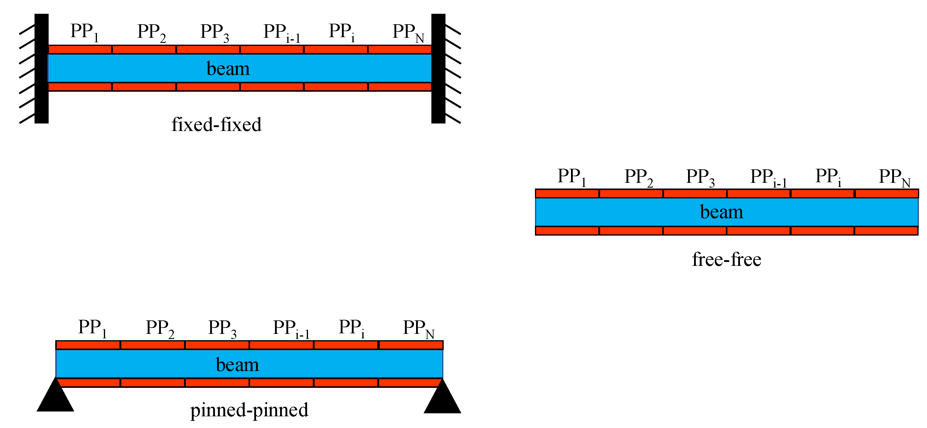
2. Optimal Voltage Distribution on Piezoelectric Actuators Coupled with Beams under Different Constraints

In Figure 1, the beams coupled with piezoelectric actuator pairs are depicted for the considered boundary conditions.
The equilibrium equation of the beam can be obtained through the principle of virtual work:
δ L e = δ L i + δ L a + δ L p
where the δ L e , δ L i , δ L a , and δ L p represent, respectively, the virtual works of elastic, inertial, external, and piezoelectric forces. In this paper, the focus will be on flexural vibrations, so that, if w represents the vertical displacement of the beam section the virtual works can be written in the form (the superimposed tilde indicates the virtual quantities):
δ L e = 0 L M e ( x , t ) w ( x , t ) d x δ L i = 0 L ρ A w ¨ ( x , t ) w ( x , t ) d x δ L a = 0 L f a ( x , t ) w ( x , t ) d x
where M e ( x , t ) = E I w ( x , t ) is the internal elastic moment while f a ( x , t ) is the external force.
By distributing the voltage on the PZT plates as reported in Figure 2, the actions exerted on the beam by each pair of actuators can be represented by a pair of bending moments M p ( t ) applied to their ends.
Denoting with:
Λ ( t ) = d 31 T a V ( t ) ψ = E b T b E a T a
the flexural moment can be written as [11,20,27]:
M p ( t ) = ψ 6 + ψ E a c T a T b Λ ( t )
The aim of this article is the identification of the optimal voltage distribution for damping modal vibrations. In this regard, the voltage V ( t ) will always be the same for each PP and only its sign varies according to a step function (Figure 3). In this way, the effect of different voltage distributions can be compared to each other.
The virtual work of the piezoelectric forces L p can be written as:
δ L p = M p i = 0 N p 1 w x | x = x i + 1 w x | x = x i δ ( V i )
where N p is the number of PPs, x i are the points where there is a change of the voltage’s sign, and the step function δ ( V i ) may assume the values +1 or −1 depending on the plate i and the considered voltage distribution (see Figure 3). In this way, the assessment of the optimal voltage distribution lies in the search for the optimal points x i where the voltage switches its sign. Let w j ( x ) be the generic vibration mode to be damped, the most effective voltage distribution will be the one that maximizes δ L p . Since M p is constant for each PP, the variation of the work δ L p will depend essentially on the differences w j x | x = x i + 1 w j x | x = x i , as a function of the different voltage distributions. This implies that it will be convenient to choose x i + 1 and x i at the extrema of the eigenmode’s first derivative to maximize such difference. However, it will also be necessary to change the voltage’s sign at each extremum in order to cumulate all the contributions and achieve the maximum damping effectiveness (Figure 4).
Thereby, the optimal voltage distribution will be obtained by changing the sign of V ( t ) at each minimum or maximum of the eigenmode’s first derivative that has to be dampened. The following formula can be used for all the considered boundary conditions to calculate the total virtual work of the piezoelectric forces:
δ L p = M p w ( x L ) w ( x 0 ) + 2 i = 1 k w ( x 2 i 1 ) w ( x 2 i )
with k being a parameter that depends on the number of the extrema points ( N e ) that appear in w · k can be found as follows:
k = N e 1 2 if there is not a maximum in x = L N e 2 2 if there is a maximum in x = L

3. Numerical Model and Results

A commercial multiphysics FEM code (COMSOL) was used to verify the analytical results on the optimal voltage distribution for several cases of beam constraints. The model geometry specifications are listed in Table 1.
The beam is entirely covered by 10 PZT actuator couples, hence 2 10 possible voltage distributions exist (Table 2) and they all are explored in order to assess the optimal one. The optimal voltage distribution is numerically evaluated by comparing the amplitudes of the displacement reached by a reference point for all the voltage distributions (with the only restriction of not selecting a node, i.e., zero-displacement point). Then, the voltage distribution that allows to obtain the maximum displacement is identified. The PZT and beam material specifications are reported in Table 3. For each considered boundary condition, the frequency response of the beam was simulated by supplying all the PPs with the harmonic voltage V ( t ) = V e j ω t , where V is the voltage amplitude (set to 100 V), j is the imaginary unit, and ω is the angular frequency corresponding to one of the first three eigenmodes. The sign of the voltage has been distributed as reported in Table 2, so 1024 frequency response simulations have been performed for each eigenmode. The beam coupled with 10 PPs is modelled in a 3D environment and its mesh consists approximately of 50,000 free-triangular elements. The edges of each PZT actuator have been refined to enhance the solution’s accuracy, since the piezoelectric moment provided by every PP is concentrated at the ends of each actuator (Section 2).
Figure 5 reports the comparison between the analytical and numerical calculated optimal voltage distribution considering the free-free boundary condition and the first three eigenmodes. As described in Section 2, the optimal voltage distribution provides a sign change whether a minimum or a maximum in the first derivative of the mode is encountered. When the first mode is excited, the best voltage distribution implies no sign change (Figure 5a). If the second mode has to be dampened, the voltage’s sign must change from x ¯ = 0.5 onwards (Figure 5b). When the third mode is excited, the most effective voltage distribution entails two voltage’s sign changes, respectively, within 0 x ¯ 0.36 and 0.64 x ¯ 1 (Figure 5c). In this case, the FEM sign switch location are slightly shifted with respect to the extrema locations of w 3 ( x ¯ ) because of the numerical discretization error. This is due to the inherent finite number of PZT plates; the edge of a PZT pair does not always coincide with an extremum of w j ( x ¯ ) . Figure 6 depicts the errors in the damping effectiveness to show the above mentioned considerations. In this case, the total analytical virtual work δ L p , a n = | δ L p 1 , a n | + | δ L p 2 , a n | + | δ L p 3 , a n | is the maximum work theoretically achievable. Since 10 PZT actuator pairs are considered in the FEM simulations, the total virtual work obtained via FEM will be always lower than δ L p , a n . δ L p , f e m and it can be written as δ L p , f e m = | δ L p 1 , f e m | + | δ L p 2 , f e m | + | δ L p 3 , f e m | δ L p , a n . The total damping effectiveness error due to the number of actuators can be written as e t o t = e 1 + e 2 . The terms e 1 and e 2 can be calculated as e 1 = δ L p 1 , a n δ L p 1 , f e m and e 2 = δ L p 3 , a n δ L p 3 , f e m . It is worth noting that δ L p 2 , a n δ L p 2 , f e m = e 1 + e 2 . The total percentage loss of damping due to the discretization can be written as:
e ( % ) = δ L p , a n δ L p , f e m δ L p , a n
For the considered cases, e ( % ) is always lower than 4–5% while, in the worst case (Figure 6), the discretization error yields to a numerical loss of damping effectiveness equal to 8%.
A similar fair agreement among the analytical and numerical outcomes can be observed for the fixed-fixed boundary condition (Figure 7). If the first mode is excited, the optimal voltage distribution entails two sign switches ( x ¯ = 0.23 and x ¯ = 0.77 ), as reported in Figure 7a. The optimal voltage distribution to damp the second mode excitation includes three sign changes (Figure 7b), while four sign switches must be provided when the third eigenmode is excited (Figure 7c).
The numerical optimal voltage distributions for the first three modes of a pinned-pinned beam (Figure 8) are similar to those of the free-free beam modes (Figure 5). This is due to the fact that the ends of the beam are free to rotate for both boundary conditions. However, the local minima and maxima of w j x ¯ share the same absolute value in the case of pinned-pinned beams (Figure 8), while this is not the case for the free-free and fixed-fixed boundary conditions.
Finally, it seems to be confirmed that the proposed method allows to theoretically find the optimal voltage distribution on PZT actuator pairs, regardless of the boundary condition, which also ensures the highest achievable piezoelectric work δ L p . In other terms, by maximizing the piezoelectric work, the maximum damping efficiency can be achieved in the case of resonance mitigation.
In Figure 9a–d the damping effectiveness of several voltage distributions reported in Table 4 are compared in the case of the resonance induced by an external load F ( t ) . The load F ( t ) = F 0 cos ( ω 1 t ) is evenly distributed on the beam length, with F 0 = 15 N and ω 1 being the angular frequency. The damping efficacy is calculated by considering the displacement of a reference point located at x ¯ = 0.2 and driving the PPs with the same voltage amplitude V = 80 V for each considered voltage distribution. It is worth noting that when the PPs within the maximum and minimum of the first derivative of the first eigenmode is not activated at all (i.e., δ V i = 0 , Equation (5)), about 50% damping effectiveness can be reached (Figure 9a). In this case, the virtual work of the piezoelectric forces is not optimized since the participation of PPs located between x ¯ = 0.2 and x ¯ = 0.8 is zero. Such a contribution can be recovered, reaching 100% damping efficacy by switching the sign of the voltage at x ¯ = 0.2, and proving the validity of the proposed method (Figure 9c). In fact, considering Figure 10, the total piezoelectric virtual work δ L p t o t can be written as:
δ L p t o t = δ L p 1 + δ L p 2 + δ L p 3
which can be normalized to highlight the individual percentage contributions:
r t o t = r 1 + r 2 + r 3 = δ L p 1 δ L p t o t + δ L p 2 δ L p t o t + δ L p 3 δ L p t o t = 1
Since the difference between the damping efficacy obtained with A and OVD 1 distributions is 50%, it can be seen that it actually coincides with r 2 because r 1 + r 3 = 50 %. When the optimal voltage distribution for the second eigenmode excitation (OVD 2 ) and B distribution are activated, the damping efficacy is way lower than that reached with the OVD 1 (Figure 9b–d).

4. Conclusions

The optimal voltage distribution to dampen the vibration at resonance has been investigated for the Euler–Bernoulli beam entirely covered with PZT actuator pairs and for different boundary conditions. The optimization method lies in the maximization of the virtual work of the piezoelectric forces that depends on the first derivative of the target mode shape. The optimal voltage distributions have been investigated for the first three eigenmodes and free-free, fixed-fixed, and pinned-pinned boundary conditions. It was numerically verified that the voltage must change its sign whenever a minimum or maximum of the piezoelectric work is reached. The numerical simulations have been performed through a FEM code considering 10 PZT actuator pairs and a fair agreement with the theoretical predictions arises for each case under study. The proposed approach may be relevant for many engineering problems involving the design of active vibration damping systems, based on the PZT actuators.

Author Contributions

Conceptualization, A.R. and F.B.; methodology, A.R. and F.B.; software, F.B.; validation, A.R. and F.B.; formal analysis, F.B.; investigation, A.R. and F.B.; data curation, A.R.; writing—original draft preparation, A.R. and F.B.; writing—review and editing, A.R. and F.B.; visualization, A.R.; supervision, F.B. All authors have read and agreed to the published version of the manuscript.

Funding

This research received no external funding.

Institutional Review Board Statement

Not applicable.

Informed Consent Statement

Not applicable.

Data Availability Statement

Not applicable.

Conflicts of Interest

The authors declare no conflict of interest.

Nomenclature

Lbeam’s length
d 31 piezoelectric coefficient
ρ beam’s density
E a Young’s modulus of the piezoelectric actuator
E b Young’s modulus of the beam
M p piezoelectric bending moment
T a piezoelectric actuator thickness
T b beam’s thickness
bbeam’s width
Abeam’s cross-section area
wvertical displacement
w virtual vertical displacement
w i ( x ) i-th flexural mode of the cantilever beam
x ¯ dimensionless length of the beam: x L b
x i points where the potential changes its sign
x ¯ = x L dimensionless length
derivative with respect to the x axis

References

  1. Tamer, O.; Walter, F.; Sinapius, M.; Böl, M. A Computational Geometric Parameter Optimization of the Thermomechanical Deicing Concept. Actuators 2022, 11, 223. [Google Scholar] [CrossRef]
  2. Shamim, M.B.; Hörsting, M.; Wulfinghoff, S. Variational Reduced-Order Modeling of Thermomechanical Shape Memory Alloy Based Cooperative Bistable Microactuators. Actuators 2023, 12, 36. [Google Scholar] [CrossRef]
  3. Nguyen, Q.A.; Jorgensen, S.; Ho, J.; Sentis, L. Characterization and Testing of an Electrorheological Fluid Valve for Control of ERF Actuators. Actuators 2015, 4, 135–155. [Google Scholar] [CrossRef] [Green Version]
  4. Oh, J.S.; Sohn, J.W.; Choi, S.B. Applications of Magnetorheological Fluid Actuator to Multi-DOF Systems: State-of-the-Art from 2015 to 2021. Actuators 2022, 11, 44. [Google Scholar] [CrossRef]
  5. Jeniš, F.; Kubík, M.; Michálek, T.; Strecker, Z.; Žáček, J.; Mazůrek, I. Effect of the Magnetorheological Damper Dynamic Behaviour on the Rail Vehicle Comfort: Hardware-in-the-Loop Simulation. Actuators 2023, 12, 47. [Google Scholar] [CrossRef]
  6. Kang, M.G.; Jung, W.S.; Kang, C.Y.; Yoon, S.J. Recent Progress on PZT Based Piezoelectric Energy Harvesting Technologies. Actuators 2016, 5, 5. [Google Scholar] [CrossRef]
  7. Aabid, A.; Parveez, B.; Raheman, M.A.; Ibrahim, Y.E.; Anjum, A.; Hrairi, M.; Parveen, N.; Zayan, J.M. A Review of Piezoelectric Material-Based Structural Control and Health Monitoring Techniques for Engineering Structures: Challenges and Opportunities. Actuators 2021, 10, 101. [Google Scholar] [CrossRef]
  8. Harti, K.E.; Rahmoune, M.; Sanbi, M.; Saadani, R.; Bentaleb, M.; Rahmoune, M. Finite Element Model of Vibration Control for an Exponential Functionally Graded Timoshenko Beam with Distributed Piezoelectric Sensor/Actuator. Actuators 2019, 8, 19. [Google Scholar] [CrossRef] [Green Version]
  9. Barrett-Gonzalez, R.; Wolf, N. High Speed Microactuators for Low Aspect Ratio High Speed Micro Aircraft Surfaces. Actuators 2021, 10, 265. [Google Scholar] [CrossRef]
  10. Barrett-Gonzalez, R.; Wolf, N. High-Rate, High-Precision Wing Twist Actuation for Drone, Missile, and Munition Flight Control. Actuators 2022, 11, 239. [Google Scholar] [CrossRef]
  11. Botta, F.; Rossi, A.; Belfiore, N.P. A novel method to fully suppress single and bi-modal excitations due to the support vibration by means of piezoelectric actuators. J. Sound Vib. 2021, 510, 116260. [Google Scholar] [CrossRef]
  12. Botta, F.; Toccaceli, F. Piezoelectric Plates Distribution for Active Control of Torsional Vibrations. Actuators 2018, 7, 23. [Google Scholar] [CrossRef] [Green Version]
  13. Botta, F.; Rossi, A. Introductory PZT actuators optimal working configuration experimental study in a turbofan engine fan rotor blade. In Proceedings of the Turbo Expo: Power for Land, Sea, and Air, Online, 21–25 September 2020; American Society of Mechanical Engineers: New York, NY, USA, 2020; Volume 84232, p. V011T30A035. [Google Scholar]
  14. Mokrani, B.; Bastaits, R.; Romanescu, I.; Horodinca, M.; Burda, I.; Preumont, A. Passive Damping of Rotationally Periodic Structures with Tuned Piezoelectric Inductive Shunt. Actuators 2018, 7, 41. [Google Scholar] [CrossRef] [Green Version]
  15. Rossi, A.; Botta, F.; Giovannelli, A.; Belfiore, N.P. High efficiency active damping on a fan rotor blade in case of resonant vibrations by means of piezoelectric actuators. In Proceedings of the ASME Turbo Expo 2021: Turbomachinery Technical Conference and Exposition, GT 2021, Online, 7–11 June 2021; Volume 9A-2021. [Google Scholar] [CrossRef]
  16. Goltz, I.; Böhmer, H.; Nollau, R.; Belz, J.; Grüber, B.; Seume, J. Piezo-Electric Actuation of Rotor Blades in an Axial Compressor. In Proceedings of the ETC 2009—8th European Conference on Turbomachinery, Graz, Austria, 23–27 March 2009. [Google Scholar]
  17. Provenza, A.J.; Morrison, C.R. Control of Fan Blade Vibrations Using Piezoelectrics and Bi-Directional Telemetry. In Proceedings of the ASME 2011 Turbo Expo: Turbine Technical Conference and Exposition, Vancouver, BC, Canada, 6–10 June 2011; American Society of Mechanical Engineers Digital Collection: New York, NY, USA, 2011; pp. 923–930. [Google Scholar]
  18. Choi, B.; Kauffman, J.; Duffy, K.; Provenza, A.; Morrison, C. Active vibration reduction of titanium alloy fan blades (FAN1) using piezoelectric materials. NASA/TM 2010, 2010, 216335. [Google Scholar]
  19. Rossi, A.; Botta, F.; Giovannelli, A.; Belfiore, N.P. A novel approach to reduce fan rotor blades stress in case of resonance due to inlet flow distortion by means of piezoelectric actuators. J. Sound Vib. 2023, 548, 117552. [Google Scholar] [CrossRef]
  20. Crawley, E.F.; De Luis, J. Use of piezoelectric actuators as elements of intelligent structures. AIAA J. 1987, 25, 1373–1385. [Google Scholar] [CrossRef]
  21. Ducarne, J.; Thomas, O.; Deü, J. Placement and dimension optimization of shunted piezoelectric patches for vibration reduction. J. Sound Vib. 2012, 331, 3286–3303. [Google Scholar] [CrossRef]
  22. Barboni, R.; Mannini, A.; Fantini, E.; Gaudenzi, P. Optimal placement of PZT actuators for the control of beam dynamics. Smart Mater. Struct. 2000, 9, 110. [Google Scholar] [CrossRef]
  23. Gupta, V.; Sharma, M.; Thakur, N. Optimization Criteria for Optimal Placement of Piezoelectric Sensors and Actuators on a Smart Structure: A Technical Review. J. Intell. Mater. Syst. Struct. 2010, 21, 1227–1243. [Google Scholar] [CrossRef]
  24. Botta, F.; Dini, D.; Schwingshackl, C.; di Mare, L.; Cerri, G. Optimal Placement of Piezoelectric Plates to Control Multimode Vibrations of a Beam. Adv. Acoust. Vib. 2013, 2013, 905160. [Google Scholar] [CrossRef]
  25. Botta, F.; Rossi, A.; Schinaia, L.; Scorza, A.; Orsini, F.; Sciuto, S.; Belfiore, N. Experimental validation on optimal placement of pzt plates for active beam multimode vibrations reduction. In Proceedings of the AIMETA 2017 Proceedings of the 23rd Conference of the Italian Association of Theoretical and Applied Mechanics, Salerno, Italy, 4–7 September 2017; Volume 3, pp. 2258–2269. [Google Scholar]
  26. Rossi, A.; Botta, F.; Maiozzi, R.; Scorza, A.; Sciuto, S.A. Experimental results for active control of multimodal vibrations by optimally placed piezoelectric actuators. MATEC Web Conf. 2018, 211, 20001. [Google Scholar] [CrossRef] [Green Version]
  27. Botta, F.; Scorza, A.; Rossi, A. Optimal Piezoelectric Potential Distribution for Controlling Multimode Vibrations. Appl. Sci. 2018, 8, 551. [Google Scholar] [CrossRef] [Green Version]
  28. Cross, R. Factors affecting the vibration of tennis racquets. Sport. Eng. 2015, 18, 135–147. [Google Scholar] [CrossRef]
  29. Brody, H. Models of baseball bats. Am. J. Phys. 1990, 58, 756–758. [Google Scholar] [CrossRef]
  30. Vigneshwaran, K.; Behera, R.K. Vibration Analysis of a Simply Supported Beam with Multiple Breathing Cracks. Procedia Eng. 2014, 86, 835–842. [Google Scholar] [CrossRef] [Green Version]
Figure 1. Beams coupled with PZT actuator pairs (PPs) for different boundary conditions: free-free, fixed-fixed, and pinned-pinned.
Actuators 12 00085 g001
Figure 2. i-th PZT actuator pair actions induced on the beam.
Actuators 12 00085 g002
Figure 3. Example of a voltage distribution on the PPs.
Actuators 12 00085 g003
Figure 4. Example of the optimal voltage distribution to achieve the maximum work δ L p for the third mode and free-free boundary condition. δ L p is only dependent on the first derivative of the eigenmode ( w 3 ( x ¯ ) ): (a) no voltage’s sign switch is provided, (b) optimal voltage distribution (two sign switches entailed). In the case (a), the total work δ L p = δ L p 1 + δ L p 2 + δ L p 3 is not the highest since the work δ L p 2 is negative and reduces the total work. Case (b) shows that the optimal voltage distribution entails two voltage sign switches, respectively, at x 1 ¯ = 0.36 and x 2 ¯ = 0.64 . In this way, the resulting total work δ L p m a x = δ L p 1 + δ L p 2 + δ L p 3 is the highest since δ L p 2 is actually positive. The solid red line represents the function w 3 ( x ¯ ) when the voltage’s sign is switched for 0.36 x ¯ 0.64 .
Actuators 12 00085 g004
Figure 5. First derivatives of the first three modes for free-free boundary condition: (a) first mode, (b) second mode, and (c) third mode. The FEM results highlight the optimal location of the voltage sign switch (illustrated with blue stars).
Actuators 12 00085 g005aActuators 12 00085 g005b
Figure 6. Example of discretization errors when evaluating the damping effectiveness in the case of free-free boundary conditions and third mode excitation. The total analytical virtual work δ L p , a n = | δ L p 1 , a n | + | δ L p 2 , a n | + | δ L p 3 , a n | is the maximum theoretically achievable. Since 10 PZT actuator pairs are considered in the FEM simulations, the total virtual work, obtained via FEM, will be always lower than δ L p , a n and it can be written as: δ L p , f e m = | δ L p 1 , f e m | + | δ L p 2 , f e m | + | δ L p 3 , f e m | δ L p , a n . e 1 and e 2 can be obtained as: e 1 = δ L p 1 , a n δ L p 1 , f e m and e 2 = δ L p 3 , a n δ L p 3 , f e m . It is worth noting that δ L p 2 , a n δ L p 2 , f e m = e 1 + e 2 . The total percentage loss of damping due to the discretization error (Equation (8)) is e ( % ) = δ L p , a n δ L p , f e m δ L p , a n = 2 e 1 + 2 e 2 δ L p , a n = 8 % .
Actuators 12 00085 g006
Figure 7. First derivatives of the first three modes for fixed-fixed boundary condition: (a) first mode, (b) second mode, and (c) third mode. The FEM results highlight the optimal location of the voltage sign switch (illustrated with blue stars).
Actuators 12 00085 g007
Figure 8. First derivatives of the first three modes for pinned-pinned boundary condition: (a) first mode, (b) second mode, and (c) third mode. The FEM results highlight the optimal location of the voltage sign switch (illustrated with blue stars).
Actuators 12 00085 g008
Figure 9. Example of the damping efficacy achieved activating the voltage distributions listed in Table 4. w x ¯ = 0.2 vs. time plots in the case of: (a) activation of the voltage distribution A, (b) activation of the voltage distribution B, (c) activation of the voltage distribution OVD 2 , and (d) activation of the voltage distribution OVD 1 . The first eigenmode of the fixed-fixed beam is excited by the external load F ( t ) , evenly distributed on the beam length, with F ( t ) = F 0 cos ( ω 1 t ) , F 0 = 15 N and ω 1 being the angular frequency of the first mode (1174.4 rad/s). The vertical displacement of a point located at x ¯ = 0.2 is used as the reference point. The dashed red line shows the instant of voltage distribution activation.
Actuators 12 00085 g009aActuators 12 00085 g009b
Figure 10. Virtual works of the piezoelectric forces ( δ L p ) in the case of the first eigenmode excitation in a fixed-fixed beam. The FEM results highlight the optimal location of the voltage sign switch (illustrated with blue stars).
Actuators 12 00085 g010
Table 1. Geometric details of the beam and each PZT actuator.
beamL (mm)b (mm) h b (mm)
300303
PZT L p (mm) b p (mm) h p (mm)
30300.3
Table 2. Possible voltage distributions.
Distribution\PP12345678910
1+1+1+1+1+1+1+1+1+1+1
2+1+1+1+1+1+1+1+1+1−1
3+1+1+1+1+1+1+1+1-+1
4+1+1+1+1+1+1+1−1+1+1
5+1+1+1+1+1+1−1+1+1+1
k+1−1+1−1−1+1−1+1+1−1
2 10 = 1024 −1−1−1−1−1−1−1−1−1−1
Table 3. PZT actuators and beam material specifications.
LabelMaterialDensity (kg/m 3 )Young’s Modulus (GPa)Poisson’s Ratio d 31 ( 10 12 C / N )
BeamAluminium2700700.3
ActuatorPZT-5A775039374
Table 4. Selected voltage distributions for the damping effectiveness comparison illustrated in Figure 9 and considering the first eigenmode excitation of the fixed-fixed beam. OVD 1 and OVD 2 are the optimal voltage distributions when the mode is excited, respectively, for the first and the second mode.
Distribution\PP12345678910
A+1+1000000+1+1
B+1+1−1−1−1+1+1−1−1+1
OVD 1 +1+1−1−1−1−1−1−1+1+1
OVD 2 +1+1−1−1−1+1+1+1+1−1
Disclaimer/Publisher’s Note: The statements, opinions and data contained in all publications are solely those of the individual author(s) and contributor(s) and not of MDPI and/or the editor(s). MDPI and/or the editor(s) disclaim responsibility for any injury to people or property resulting from any ideas, methods, instructions or products referred to in the content.

